Hollow core floor systems: increasing performances with ...
20
Hollow core floor systems: Hollow core floor systems: increasing performances increasing performances with composite action with composite action S. Bernardi CERIB Study and Research Centre for the French Concrete Industry
Transcript of Hollow core floor systems: increasing performances with ...

Hollow core floor systems: Hollow core floor systems: increasing performances increasing performances with composite actionwith composite action
S. Bernardi
CERIBStudy and Research Centre for the French Concrete Industry

2
IPHA Workshop – 7 & 8 November 2005 – Delft
Precast prestressedPrecast prestressedhollow core floorshollow core floors
World annual production ≈ 200 millions m2
2 millions m2 in France
Principally used for:offices buildingscommercial and industrial buildingsparkings

3
IPHA Workshop – 7 & 8 November 2005 – Delft
Precast prestressedPrecast prestressedhollow core floorshollow core floors
Hollow core slabs produced in France:
12 cm ≤ thickness ≤ 40 cm60% extruded / 40% slipformed95% with protruding tendons
16 cm
20 cm26,5 cm
32 cm
40 cm

4
IPHA Workshop – 7 & 8 November 2005 – Delft
Types of supportsTypes of supports
• reinforced concrete walls• reinforced concrete beams• prestressed concrete beams• metallic beams
rigid supports
increase of bending and shear capacities of the beam?
flexible supports
reduction of the shear capacity of hollow core slabs?

5
IPHA Workshop – 7 & 8 November 2005 – Delft
Composite actionComposite actionStresses state in the web
σ1 is due to the effectiveprestressing force
τ1 is due to the vertical shear force
τ2 is due to the shear flow in the transversal direction
τ3 is due to the shear flow in the longitudinal direction
τ3 τ3

6
IPHA Workshop – 7 & 8 November 2005 – Delft
Research in CERIBResearch in CERIBAims
Secondly to identify the configurations
where the flexibility of the support shall
be considered (flexible supports)
numerical modellingfull scale tests
First to elaborate an analytical model for
designing beams when hollow core slabs behave as
compressive flange (rigid supports)

7
IPHA Workshop – 7 & 8 November 2005 – Delft
Experimental studyExperimental study
Description of the floors tested
Hollow core slabs:- thickness= 26,5 cm / length= 8,00 m- strands: 10 T12,5 (protruding length = 10 cm)- concrete class C60/75
Middle beam for 1st test:- prestressed concrete beam- section= 40 x 40 cm- length= 4,50 m- strands: 10 T15,2 (σp0 = 1517 MPa)- passive: 5 Φ12- concrete class C50/60
Middle beam for 2nd test:- metallic beam- I profile (height= 17,5 cm)- length= 4,50 m- steel grade 240

8
IPHA Workshop – 7 & 8 November 2005 – Delft
Experimental studyExperimental study
Test n° 1 concrete beam
concrete C25/30 4 HA 10
100hollow core slab 26,5 cm thickness
polystyrene plug
100 20
300 400
5 5
175
265studs
φ12 anchored in the joint
Test n° 2 metallic beam
9
IPHA Workshop – 7 & 8 November 2005 – Delft
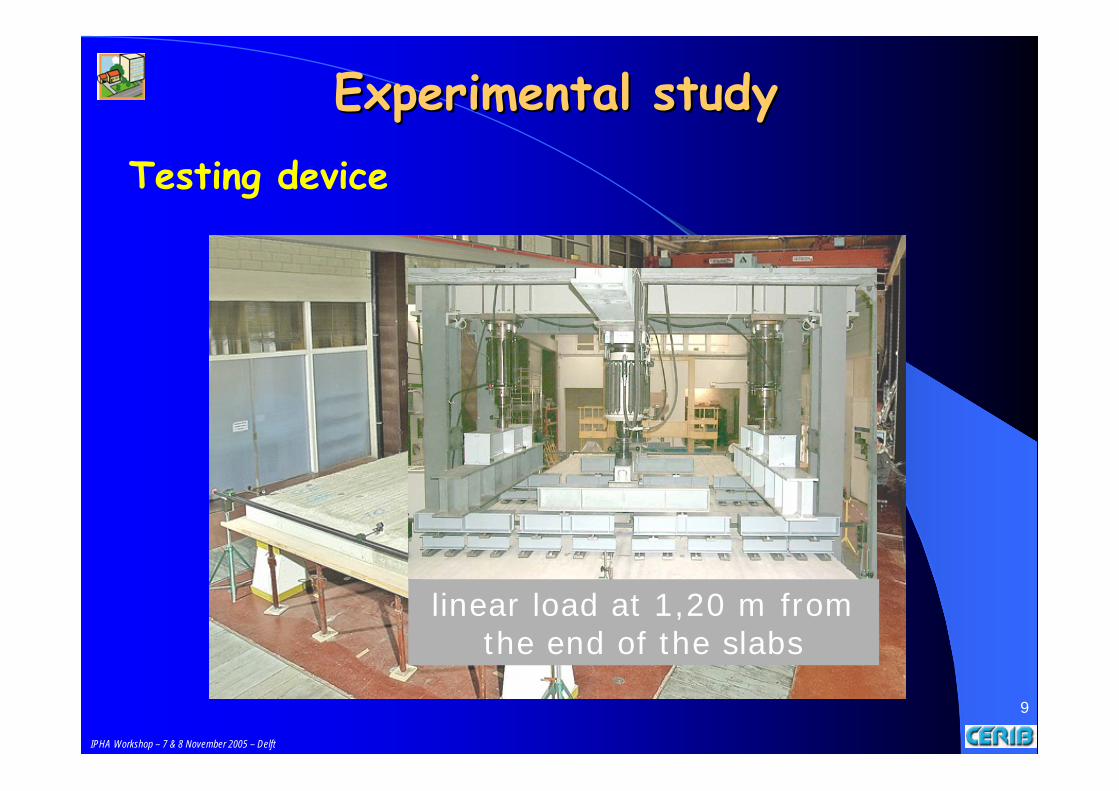
Experimental studyExperimental studyTesting device
linear load at 1,20 m from the end of the slabs

10
IPHA Workshop – 7 & 8 November 2005 – Delft
Experimental studyExperimental studyMeasurement
Strain gauges for:tensile strain of the beam at mid-spanprincipal strains in the webs
Inductive transducers for:vertical displacement of slabs and beamdifferential horizontal displacement between the slabs and
the middle beamcrack width in the vertical joint concrete between the slabs
and the middle beamwarping of the webs of hollow core slabs

11
IPHA Workshop – 7 & 8 November 2005 – Delft
Numerical studyNumerical studyFinite elements model (Castem 2000)• 3D analysis with cubic elements for modelling slabs, beams and joints and bar elements for reinforcement• elastic behaviour for concrete (slabs and beam) and steel• isotropic damage law for the interfaces and joints
-25
-20
-15
-10
-5
0-0.008 -0.006 -0.004 -0.002 0 0.002
Displacement in the loading direction (mm)
0
0.5
1
1.5
2
2.5
0 0.02 0.04 0.06 0.08 0.1 0.12 0.14 0.16
Displacement in the loading direction (mm)

12
IPHA Workshop – 7 & 8 November 2005 – Delft
Experimental Experimental & & Numerical resultsNumerical resultsLocation of failure
failure of test n° 1Vu,test = 210 kN
failure of test n° 2Vu,test = 140 kN
1,250,970,950,74γc = 1,5 / γs = 1,15
1,941,502,241,74γc = γs = 1,0test No.2test No.1test No.2test No.1
Eurocode 2French rulesShear resistanceratio (design/test)

13
IPHA Workshop – 7 & 8 November 2005 – Delft
Experimental Experimental & & Numerical resultsNumerical resultsFailure load
Test n° 1 Test n° 2
no longitudinal cracking along the strands

14
IPHA Workshop – 7 & 8 November 2005 – Delft
Experimental Experimental & & Numerical resultsNumerical results
0
50
100
150
200
250
300
350
400
450
500
0 1 2 3 4 5 6 7Mid-span vertical deflection of beam (mm)
App
lied
forc
e (k
N)
test No. 1model No. 1test No.2model No. 2
0
50
100
150
200
250
300
350
400
450
500
0 2 4 6 8 10 12 14 16 18 20Vertical deflection of slabs (mm)
App
lied
forc
e (k
N)
test No.1model No.1test No.2model No.2
Deflection

15
IPHA Workshop – 7 & 8 November 2005 – Delft
Experimental Experimental & & Numerical resultsNumerical resultsShear stresses
0
50
100
150
200
250
300
350
400
450
500
0 1 2 3 4 5 6 7Vertical shear stress(MPa)
App
lied
forc
e (k
N)
test No.1model No.1test No.2model No.2
0
50
100
150
200
250
300
350
400
450
500
0 0.2 0.4 0.6 0.8 1 1.2Horizontal shear stress (MPa)
App
lied
forc
e (k
N)
test No.1
model No.1
test No.2
model No.2

16
IPHA Workshop – 7 & 8 November 2005 – Delft
Effective Effective widthwidthcomposite section
Effective width : beff = L/10 (L is the span of the beam)
Value confirmed by experimental results on deflection and normal stresses

17
IPHA Workshop – 7 & 8 November 2005 – Delft
Analytical modelAnalytical modelbending moment
applied to the beam
Mp = Mext (1 – K)
reduction coefficient due to composite action
⎥⎥⎦
⎤
⎢⎢⎣
⎡
⎟⎟⎠
⎞⎜⎜⎝
⎛+
δ+
=
TT
pp2
p
p
AEAE
1A
I1
1K
)1(1
IEIE)x(M)x(M 2pp
DDpD ν−
=transverse bendingmoment applied to the slabs
Ap : cross section of the beam (precast beam + in-situ concreteAT : cross section of the compressive flangeIp / ID : second moment of area of the beam / of the hollow core slabEp / ET / ED : modulus of elasticity of concrete of the beam / of the flange
/ of the hollow core slab

18
IPHA Workshop – 7 & 8 November 2005 – Delft
Analytical modelAnalytical model
d8,0MM
21V pext
sd−
=
effw
sd2bb
V=τshear stress due to
the shear flow in thetransversal direction:
ctw
sd3 hb
V=τshear stress due to the shear flow in thelongitudinal direction:
(applied load = 300 kN / γG = 1,35 ; γQ = 1,5)
3,60 MPa1,52 MPaτ3
3,28 MPa1,38 MPaτ2
test No.2test No.1
Design shear stresses
3,60 MPa1,52 MPaτ3
3,28 MPa1,38 MPaτ2
test No.2test No.1
Design shear stressesFinnish rulesCode Card 18
2,85 MPa1,39 MPa
test No.2test No.1
2,85 MPa1,39 MPa
test No.2test No.1

19
IPHA Workshop – 7 & 8 November 2005 – Delft
The influence of the rigidity of the support on the mechanical behaviour of the floor system has been highlighted.
The outcome with the model is good with respect to the available experimental results.
The design method will be incorporated into a new French standard for erection and design of hollow core floor systems.
ConclusionsConclusions

20
IPHA Workshop – 7 & 8 November 2005 – Delft
Thank you Thank you for for your your attentionattention
Questions ?Questions ?