HOLLOW AMERICAN NATIONAL STANDARD 9511 Cover P2 3/30/05 11:52
36
HMMA 863 A Division of NATIONAL ASSOCIATION OF ARCHITECTURAL METAL MANUFACTURERS ANSI/NAAMM HMMA 863-04 January 26, 2005 METAL DOORS & FRAMES 8d ANSI/NAAMM HMMA 863-04 January 26, 2005 METAL DOORS & FRAMES 8d HOLLOW METAL MANUFACTURERS A S S O C I A T I O N -04 HOLLOW METAL MANUAL ANSI/ NAAMM AMERICAN NATIONAL STANDARD GUIDE SPECIFICATIONS FOR DETENTION SECURITY HOLLOW METAL DOORS AND FRAMES FIFTH EDITION
Transcript of HOLLOW AMERICAN NATIONAL STANDARD 9511 Cover P2 3/30/05 11:52

HMMA 863
A Division of
NATIONAL ASSOCIATION OFARCHITECTURAL METAL MANUFACTURERS
AN
SI/N
AA
MM
HM
MA
863
-04
Janu
ary
26, 2
005
ME
TA
L D
OO
RS
& F
RA
ME
S8d
AN
SI/N
AA
MM
HM
MA
863-04January 26, 2005
ME
TA
L DO
OR
S &
FR
AM
ES
8d
HOLLOW METAL MANUFACTURERSA S S O C I A T I O N
-04
HOLLOWMETAL
MANUALANSI/NAAMM
AMERICAN NATIONAL STANDARD
GUIDE SPECIFICATIONSFOR DETENTION SECURITY
HOLLOW METALDOORS AND FRAMES
FIFTH EDITION
9511_Cover_P2 3/30/05 11:52 AM Page 2

Approval of an American National Standard requires verification by ANSIthat the requirements for due process, consensus, and other criteria forapproval have been met by the standards developer.
Consensus is established when, in the judgment of the ANSI Board ofStandards Review, substantial agreement has been reached by directlyand materially affected interests. Substantial agreement means muchmore than a simple majority, but not necessarily unanimity. Consensusrequires that all views and objections be considered, and that a concert-ed effort be made toward their resolution.
The use of American National Standards is completely voluntary; theirexistence does not in any respect preclude anyone, whether they haveapproved the standards or not, from manufacturing, marketing, purchas-ing, or using products, processes, or procedures not conforming to thestandards.
The American National Standards Institute does not develop standardsand will in no circumstances give an interpretation of any AmericanNational Standard. Moreover, no person shall have the right or authorityto issue an interpretation of an American National Standard in the nameof the American National Standards Institute. Requests for interpretationshould be addressed to the sponsor whose name appears on the titlepage of this standard.
CAUTION NOTICE: This American National Standard can be revised orwithdrawn at any time. The procedures of the American NationalStandards Institute require that action be taken periodically to reaffirm,revise, or withdraw this standard. Purchasers of American NationalStandards can receive current information on all standards by calling orwriting the American National Standards Institute.
This standard was developed by representative members of the HollowMetal Manufacturers Association Division (HMMA) of the NationalAssociation of Architectural Metal Manufacturers (NAAMM) to providetheir opinion and guidance on the specification and use of detention secu-rity hollow metal doors and frames. This standard contains advisory infor-mation only and is published as a public service by NAAMM and itsHMMA Division.
NAAMM AND ITS HMMA DIVISION DISCLAIM ALL LIABILITY OF ANYKIND FOR THE USE, APPLICATION, OR ADAPTATION OF MATERIALPUBLISHED IN THIS STANDARD.
Current information on all NAAMM Standards is available by calling, writ-ing or visiting the website of the National Association of ArchitecturalMetal Manufacturers, www.naamm.org.
National Association of Architectural Metal Manufacturers8 South Michigan Avenue
Chicago, Illinois 60603Tel: 312-332-0405 • Fax: 312-332-0706
www.naamm.org
Copyright © 1985, 1987, 1990, 1998, 2005National Association of Architectural Metal Manufacturers
All Rights Reserved
9511_Cover_P3 3/30/05 11:52 AM Page 3

TABLE OF CONTENTSIntroduction..................................................................................................................................................ii
Foreword.....................................................................................................................................................vii
Part 1 – GENERAL1.01 Summary...........................................................................................................................................1
1.02 Products Provided Under This Section...........................................................................................1
1.03 Related Sections..............................................................................................................................1
1.04 References .......................................................................................................................................2
1.05 Testing and Performance ...............................................................................................................3
1.06 Quality Assurance ...........................................................................................................................7
1.07 Submittals .........................................................................................................................................7
Part 2 – PRODUCTS2.01 Detention Security Hollow Metal Doors........................................................................................8
2.02 Detention Security Hollow Metal Panels.....................................................................................11
2.03 Detention Security Hollow Metal Frames ...................................................................................11
2.04 Manufacturing Tolerances ...........................................................................................................14
2.05 Hardware Locations......................................................................................................................16
2.06 Finish................................................................................................................................................16
Part 3 – EXECUTION3.01 Site Storage and Protection of Materials ...................................................................................17
3.02 Installation ......................................................................................................................................17
3.03 Clearances.....................................................................................................................................19
Part 4 – APPENDIX (Not part of the Standard)A1 HMMA-803-97, Steel Tables ..........................................................................................................A1
A2 HMMA-820 TN01-03, Grouting Hollow Metal Frames ................................................................A2
A3 HMMA-810 TN01-03, Defining Undercuts ....................................................................................A3
ANSI/NAAMM HMMA 863-04 DETENTION SECURITY HOLLOW METAL DOORS AND FRAMES i
9511_Body_P1 3/30/05 1:33 PM Page i

HOLLOW METAL DETENTION SECURITY SYSTEMS
Detention security hollow metal doors and frames have been successfully used in detention and correctionalfacilities throughout the world. Architects, specifiers and end users understand the advantages of usingDetention Security Hollow Metal in these applications.
HARDWARE INSTALLATION AND MAINTENANCE
To understand the advantages of hollow metal construction, consider first the hardware installation for theswinging door of a typical bar-grille cell front. The security hinges and lock encasement are actually accessibleto the inmate since he is able to reach through the bars. Therefore, in many cases, the lock encasement mustbe continuously welded assemblies with cover plates welded in place to prevent inmate tampering. Thissituation makes repairs and maintenance both difficult and expensive. For example, to repair a lock it isnecessary to cut the cover plate loose with a torch, repair or replace the lock, then weld a new cover plateback in place.
In the hollow metal assembly, the lock is mounted in a reinforced pocket, inside the door or frame and isprotected by a heavy gauge cover plate fastened with security screws. The flush type detention hollow metaldoor, examples shown in Figure 1, severely limit the inmate's access and visibility in any attempts to tamperwith the cover plate and lock. Since inmate tampering is limited by the flush hollow metal design, cover platesand access panels can be mounted with tamper resistant screws in most cases rather than welding, therebyreducing the cost of installation, repair and maintenance.
ii DETENTION SECURITY HOLLOW METAL DOORS AND FRAMES ANSI/NAAMM HMMA 863-04
INTRODUCTION
FIGURE 1Typical Door Elevations
9511_Body_P2 3/30/05 1:34 PM Page ii

ANSI/NAAMM HMMA 863-04 DETENTION SECURITY HOLLOW METAL DOORS AND FRAMES iii
HOLLOW METAL VERSUS BAR-GRILLE CONSTRUCTION
Bar-grille assemblies are manufactured by a variety of methods. However, regardless of the method used, theend result must be an assembly, which has been “hardened” against attack or tampering. By its design, bar-grille allows access by the inmate to the outside of the enclosure and thereby access to lock and positionswitch encasement, as well as conduit casements. Also, the bars themselves must be made resistant againsttool attack, again because they are accessible to the inmate. The security of bar-grille assemblies isaccomplished by various means depending upon the manufacturer’s philosophy and methods; however, thebottom line is that the heavy material, heat treating processes, and assembly processes necessary areexpensive.
On the other hand, consider typical detention hollow metal assemblies as shown in Figure 1. The frame isfabricated of pressed steel sections with integral doorstops and is fully grouted after installation. It is preparedfor the appropriate security hardware including conduit routed internally, junction boxes and access openingswith cover plates as necessary for wiring installations. The door can be a typical detention security type,prepared for security hinges, electrical or mechanical detention security lock, and position switch indicator.The door preparation can include conduit routed internally to suit electrically operated hardware whenapplicable. When confined, the inmate has no access to the outside of the enclosure because there are nogrille openings except where desired in the design. This means that security can be obtained by limitedaccessibility to sensitive areas of the opening such as locks, hinges and position indicators. Heat treatmentis not required for the steel used in the detention hollow metal construction. Because of the materials andmanufacturing processes used, the hollow metal construction costs in most cases are considered economical.
SAFETY, SECURITY, AND WELFARE
The safety, security and welfare of staff, as well as inmates, are enhanced by hollow metal construction. Inthe typical bar-grille cell front, the inmate not only has access to all of the hardware, as mentioned previously,but also has numerous opportunities to abuse or injure a staff member or other inmates by throwing objectsor bodily fluids or by grabbing them through the bars. Blood and fluid borne diseases such as tuberculosisand the HIV virus accentuate this risk. Although the installation is secure, the dangers to people passing byin corridors are still considerable. When bar grille is used, corridors often must be wider to help minimizethese problems. Also, bar installations do not inhibit an inmate from rattling the door, clanging the bars andgenerally making life miserable for other inmates and staff.
The advantages of the hollow metal cell front are evident. As shown in Figure 1, there are no openings throughwhich an inmate can reach and harm passers-by. The only openings are staff controlled openings, such as afood-pass. The reduction of visibility, which can occur in a hollow metal assembly, is offset by the properplacement of security glass, perforated plate, wire mesh screen or grille. Any combination of these optionscan be incorporated into a hollow metal door or frame to provide adequate visibility for the purpose of staffobservation. Cell fronts can be designed using side-light frames for better visibility into cells.
Caution: It is not advisable to locate glass preparations in close proximity to hardware preparations at the dooredge, since this can be detrimental to door stiffness.
The door construction itself also reduces, even though it cannot completely eliminate, the opportunity formaking noise and creating a disturbance. Because of the internally stiffened, insulation filled construction ofthe door, the inmate will only be able to make a dull, thudding noise if he chooses to beat and kick the cellfront. Also the full grouted jambs and mullions are highly effective for noise control.
9511_Body_P3 3/30/05 1:34 PM Page iii

iv DETENTION SECURITY HOLLOW METAL DOORS AND FRAMES ANSI/NAAMM HMMA 863-04
DESIGN VERSATILITY WITH HOLLOW METAL
Hollow metal construction provides the Architect with a great deal offreedom in the design of cell fronts as well as security window walls,guard enclosures and control stations while keeping costs withinreasonable limits. The Architect can also take advantage of theexpertise acquired by those hollow metal manufacturers who have hadexperience in detention security work. Over the years NAAMM/HMMAmanufacturers have developed advanced methods and equipmentenabling them to efficiently manufacture hollow metal assemblies,which address today's difficult detention applications. Theseapplications include working with the latest in electronic hardware,security glazing and detention screening. A number of thesemanufacturers offer proven economical and functional designs of theirown for cell fronts, hardware preparations, security windows withshutters, vision panels, security vent grilles, speaking devices, foodpasses, access doors, sound retardant doors and panels, observationwindows and gun ports, hollow metal wall systems, and other items.Some manufacturers also have the capability of producing heavy-dutyprison furniture such as cell bunks, desks, shelves, mess hall tables,benches, etc. Typical security window and guard control stationinstallations are shown in Figures 2 and 3 respectively.
EVALUATING DETENTION SECURITY DOORS
In order to evaluate the performance of detention security doors it has been necessary to develop testingmethods which simulate in the laboratory the use and abuse to which such doors can be subjected when inuse in correctional facilities. One objective of this development work is to provide standardized methods ofmeasuring performance, which the Architect can call for in their specifications. Another objective is to providemanufacturers standardized means of testing and inspecting their products, improving their designs andmaintaining high quality construction. Finally, maintenance of rigorous standards and methods of testingconstruction and performance give assurance of protection to the public, the prison employees and theinmates themselves. The performance requirements and methods of testing set forth in this voluntarystandard should go a long way towards realizing the stated objectives.
FIGURE 2Typical Security Cell Window
FIGURE 3Typical Control Room Details
9511_Body_P4 3/30/05 1:34 PM Page iv

ANSI/NAAMM HMMA 863-04 DETENTION SECURITY HOLLOW METAL DOORS AND FRAMES v
TESTING
Six tests are required by this specification, which are conducted in accordance with ASTM F 1450, “StandardTest Methods for Hollow Metal Swinging Door Assemblies for Detention Facilities”, and ASTM F 1592,“Standard Test Method for Detention Hollow Metal Vision Systems”.
A. Door Assembly Impact Load Test – ASTM F 1450
B. Sidelight and Multi-Light Assembly Impact Test – ASTM F 1592
C. Door Static Load Test – ASTM F 1450
D. Door Rack Test – ASTM F 1450
E. Door Edge Crush Test – ASTM F 1450
F. Bullet Resistance Test – ASTM F 1450, ASTM F 1592 & UL-752
Under the static load and rack tests a completely fabricated door, including hardware and vision light, issubjected to specified loads. In the case of the static load test the performance standard requires that thedoor not exceed a specified maximum deflection when a specified load is centrally applied at the quarter pointsof the door. In the case of the rack test, one corner of the door is left unsupported and must not exceed aspecified maximum deflection when a specified concentrated load is applied at the unsupported corner.
Static load and rack tests are prerequisites to all other testing. They provide the basis for checking integrityof construction methods, quality of welds, strength of materials and rigidity of the door assembly. However,these two tests alone are not considered adequate measurements of performance. The static load test doesnot simulate the punishment a door can receive when it is installed in a prison. It only evaluates how well thedoor performs as a simply supported beam. The rack test does evaluate the resistance of a door to endtorque, which provides some indication of the ability of the door to resist an attempt to pry open the door atthe top or bottom corner. Furthermore, the two tests lead one to believe that the greater the rigidity the betterthe performance. This can be misleading in as much as there are definite performance advantages associatedwith the qualities of limited flexibility and resilience in a door exposed to field conditions. So while these twotests are valuable in the evaluation of the basic design and construction, additional testing is needed to betterevaluate how the door will perform under conditions, which can occur in a prison.
The impact load test provides a much more realistic measure of a door's ability to withstand the treatment itcan receive under riot conditions. For this test a door complete with hardware is mounted in its frame with theentire assembly in the vertical position so that the door and locking hardware are operable. The door is thensubjected to a series of impact loads from a pendulum ram. The repetitive impact load specified in thisstandard was established by experimentation that determined what a person with a sledgehammer or severalpersons with a battering ram could develop in the way of impact energy per blow. From consultations withprison officials the time usually required to restore order in a major riot situation was ascertained. It wasassumed that a person or persons could assault a door throughout this period of time and based on thisassumption the total number of impacts to which the door would be subjected was determined. Uponcompletion of the impact testing it is required that the door still be operable. This is indeed a rigorous test andone which when added to the bullet resistance test gives a good indication as to the performance, which canbe expected of a door under riot conditions. The sidelight, window and multi-light tests are also done withimpact loads. Their purpose is to assure that the frame construction and the removable glass stops used inthe frame, are at least equal to the strength of the doors and security glazing they support.
The bullet resistance test is conducted in accordance with UL Standard 752, Level 3. In this test a superpower rated handgun is used. A rifle, which is more powerful than a handgun is not addressed because thepossibility of an inmate obtaining a rifle is very remote, and a rifle is more difficult to conceal and smuggle intopublic or secure areas. The term “bullet-resisting” as used in the UL standard signifies protection againstcomplete penetration, passage of fragments of projectiles, or spalling (fragmentation) of the protective materialto the degree that injury would be caused to a person standing directly behind the bullet-resisting barrier.
9511_Body_P5 3/30/05 1:34 PM Page 1

vi DETENTION SECURITY HOLLOW METAL DOORS AND FRAMES ANSI/NAAMM HMMA 863-04
CONSTRUCTION
The parts of this standard which cover construction specify the types of steel to be used and the minimumacceptable thickness for different applications. The products covered are doors, frames, fixed windows,hardware reinforcements, glass moldings and stops, louvers, speaking devices, food pass openings, flooranchors, jamb anchors, plaster guards, and removable glazing stops. Construction requirements are veryprescriptive and describe how doors can be welded, how stiffeners can be formed and fastened to the facesheets, how vertical edges can be reinforced, what is required for top and bottom closing channels and howthey can be welded, and what can be used for hardware reinforcements and how such reinforcements can beapplied. The same kind of detailed prescriptive requirements are given for all of the other products covered.This has been done to provide the Architect with designs for detention security products, which have beenproven by testing and by historical performance in correctional facilities. Such prescriptive requirements arenot intended to restrict innovative design, but NAAMM recommends that any alternative construction besubjected to the performance and testing requirements set forth in this standard before being accepted fordetention security installations.
CONCLUSION
This standard will prove very useful to architects concerned with the design of correctional facilities. NAAMMmembers who manufacture detention security hollow metal products stand ready to assist Architects in theirdesign and specification of these products. Send questions and/or comments on this standard to the NAAMMoffice.
9511_Body_P6 3/30/05 1:34 PM Page 2

ANSI/NAAMM HMMA 863-04 DETENTION SECURITY HOLLOW METAL DOORS AND FRAMES vii
These specifications have been prepared in accordance with CSI Section Format: Part 1 - General, Part 2 -Product and Part 3 - Execution. Guide specifications are intended to be used as the basis for developing jobspecifications and must be edited to fit specific job requirements. Inapplicable provisions shall be deleted,appropriate selections shall be made where there are choices, and provisions applicable to the job shall beadded where necessary. Optional items or requirements are shown in brackets. Notes and instructions tospecifiers are given in italics directly following the paragraphs to which they apply. Notes that containpermissive language are not considered part of the standard. Dates given with ASTM and otherstandards were current at the time this specification was published, and define the specific standardsreferenced herein. When a more recent standard is available, the specifier should verify its applicability to thisguide prior to its inclusion. While the CSI Section Format locates Delivery, Storage, and Handling in Part 1,NAAMM Standards include them under Part 3 – Execution.
Materials and fabrication methods are specified in detail in Part 2. Doors and frames made in accordance withthese specifications have successfully met the testing and performance requirements of Section 1.05.However, the materials and fabrication methods called for in these specifications, while providing a soundguide, are not meant to restrict the use of other materials and methods where it can be demonstrated throughthe specified testing procedures in Section 1.05 that the construction can equal or exceed the performancelevels specified in this section. In order to ensure that a manufacturer's product meets the desiredperformance levels, the project specifications shall include the testing and performance requirements ofSection 1.05 and the Quality Assurance requirements of Section 1.06.
The values stated in inch-pound units are to be regarded as the standard. Corresponding metric values areincluded in parentheses for reference purposes only.
Security grades were added in the 5th Edition in response to input from members of the architecturalcommunity, particularly those who are regularly involved in the design of Detention and Correctional Facilitiesand are also involved in ASTM standards development efforts for these facilities. The four (4) security gradelevels cited in the specification refer not only to the HMMA performance requirements for detention hollowmetal, but also to related ASTM standards that have been recently developed for detention hollow metal, locks,and sliding door devices. These grade levels provide a quick reference to performance standards outsideHMMA, which are coordinated with this HMMA specification and can be easily used when writing projectspecifications.
The CSI Master Format ’95 which placed detention products in Sections 08000 and 11190 has been relocatedin Master Format 2004. Section 08 34 63.13 is the new CSI location for steel detention doors and frames, andSection 11 19 13 is designated for detention pass-through doors. Specifiers can use either the old or newnumbers in their contract documents to incorporate specifications for detention doors and frames. However,the Specifier shall not utilize both systems within the same set of construction documents.
This standard indicates both CSI Section 11190 (or 08320) and [11 19 00 (or 08 34 63.13)] for detentionsecurity hollow metal doors and frames until all specifiers have switched to the new Format.
FOREWORD
9511_Body_P7 3/30/05 1:34 PM Page 3

9511_Body_P8 3/30/05 1:34 PM Page 4

ANSI/NAAMM HMMA 863-04 DETENTION SECURITY HOLLOW METAL DOORS AND FRAMES 1
CSI SECTION 11190 (or 08320) [11 19 00 (or 08 34 63.13)]DETENTION SECURITY HOLLOW METAL DOORS AND FRAMES
PART 1 - GENERAL1.01 SUMMARY
This Section includes detention security hollow metal [bullet resistant] products as shown in the contractdocuments and as specified herein.
1.02 PRODUCTS PROVIDED UNDER THIS SECTION
A. Detention security hollow metal [bullet resistant] doors with [3 hour] [11/2 hour] [3/4 hour] [1/3 hour]fire rating, [swinging type] [and/or] [sliding type] as shown in the approved submittal drawings andas specified herein.
B. Detention security hollow metal [bullet resistant] doors shall include [glass molding and stops][louvers] [speaking devices] [food pass openings] [other] as shown in the approved submittaldrawings and specified herein.
C. Detention security hollow metal [bullet resistant] panels with [3 hour] [11/2 hour] [3/4 hour] [1/3 hour]fire rating of the same construction as the detention security doors.
D. Detention security hollow metal [bullet resistant] [and/or] [fire rated] frames for [3 hour] [11/2 hour] [3/4 hour] [1/3 hour] fire rating with anchors. Transom frames, side-light, multi-light, and windowassemblies, including [glass moldings and stops] [louvers] [hollow metal panels] [other], as shownin the approved submittal drawings.
E. Detention security hollow metal [bullet resistant] frames shall include [speaking devices] [pass thrudevices] [gun ports] [other] as shown in the approved submittal drawings and specified herein.
Indicate bullet resistant doors, frames and panels only if applicable tothe job. If these are to be fire-rated doors, frames and panels, indicatethe required rating for each: 3 hour, 1-1/2 hour, 3/4 hour, or 1/3 hour.Also, indicate the type of door operation required (swinging and/orsliding), those items in 1.02.B which are to be included with the doors,and those items in 1.02.D & E which are included with the frames.
1.03 RELATED SECTIONS
A. Section 03300[03 30 00] - - - - Cast in Place Concrete: Item(s)
B. Section 03350[03 35 00] - - - - Concrete Floor Finishing: Item(s)
C. Section 03400[03 40 00] - - - - Pre-cast Concrete: Item(s)
D. Section 04200[04 20 00] - - - - Masonry System: Item(s)
E. Section 05120[05 12 00] - - - - Structural Steel: Item(s)
F. Section 08110[08 11 13] - - - - Hollow Metal Doors and Frames
G. Section 08113[08 34 53] - - - - Security Hollow Metal Doors and Frames
H. Section 08130[08 11 19] - - - - Stainless Steel Hollow Metal Doors and Frames
I. Section 08348[08 34 73]- - Swinging Sound Control Hollow Metal Doors and Frames
J. Section 08580[08 56 00] - - - - Operable Windows
K. Section 08720 (or 11190) [08 71 63] - - Gaskets and Weather-strip
L. Section 08740[08 74 00] - - - - Detention Locking Control Systems: Item(s)
M. Section 08800 (or 11190) [08 88 53] - - Security Glazing
N. Section 09900[09 90 00] - - - - Painting and Coating: Item(s)
O. Section 11190 (or 08780) [08 71 63] - - Detention Hardware
P. Section [ ] - - - Installation of Detention Security Hollow Metal Doors and Frames
9511_Body_P9 04:11:05 14:29 Page 1

2 DETENTION SECURITY HOLLOW METAL DOORS AND FRAMES ANSI/NAAMM HMMA 863-04
Not included in section 11190 (08320) [11 19 00 (08 34 63.13)] areinstallation of doors, frames, panels, door hardware or rough hardwareof any kind, weather-stripping, gasketing, operable windows, itemsfurnished by others, field painting, or protection at the building site ofproducts furnished under this Section.
1.04 REFERENCES
The publications listed in this section form a part of this specification tothe extent referenced in the specification text. The publications arereferenced in the text by basic designation only. When a more recentstandard is available, the specifier should verify its applicability to thisGuide prior to its inclusion.
A. ANSI A 250.10 – 1998, Standard Test Procedure and Acceptance Criteria for Prime Painted SteelSurfaces for Steel Doors and Frames
B. ANSI / NAAMM HMMA 801-98, Glossary of Terms for Hollow Metal Doors and Frames
C. ANSI / NAAMM HMMA 866-01, Guide Specifications for Stainless Steel Hollow Metal Doors andFrames
D. ANSI / NFPA 80-1999, Fire Doors and Windows
E. ANSI / NFPA 105-2003, Standard for the Installation of Smoke Control Door Assemblies
F. ANSI / NFPA 252-2003, Standard Methods of Fire Tests of Door Assemblies
G. ANSI / NFPA 257-2000, Methods for Fire Test of Window Assemblies
H. ANSI / UL 9-2000, Fire Tests of Window Assemblies, 7th Edition
I. ANSI / UL 10B-2001, Fire Tests of Door Assemblies, 9th Edition
J. ANSI / UL 10C-2001, Standard for Positive Pressure Fire Tests of Door Assemblies, 1st Edition
K. ASTM A 653 / A 653M-03, Specification for Steel Sheet, Zinc-coated (Galvanized) or Zinc-Iron Alloy-Coated (Galvannealed) by the Hot Dipped Process, (Commercial Steel)
L. ASTM A 666-00, Standard Specification for Annealed or Cold-Worked Austenitic Stainless SteelSheet, Strip, Plate and Flat Bar.
M. ASTM A 1008 / A 1008M-03, Specification for Steel, Sheet, Cold-Rolled, Carbon, Structural, High-Strength Low-Alloy and High-Strength Low-Alloy with Improved Formability
N. ASTM A 1011 / A 1011M-03, Specification for Steel, Sheet and Strip, Hot-Rolled, Carbon,Structural, High-Strength Low-Alloy and High-Strength Low-Alloy with Improved Formability
O. ASTM C 143 / C 143M-00, Standard Test Method for Slump of Hydraulic Cement Concrete
P. ASTM F 1450-97, Standard Test Methods for Hollow Metal Swinging Door Assemblies for Detentionand Correctional Facilities.
Q. ASTM F 1592-01, Standard Test Methods for Detention Hollow Metal Vision Systems
R. CAN4-S104 M80, Standard Method for Fire Tests of Door Assemblies
S. CAN4-S106-M80, Standard Method for Fire Tests of Window and Glass Block Assemblies
T. ICBO UBC 7-2 (1997), Fire Tests of Door Assemblies
U. ICBO UBC 7-4 (1997), Fire Tests of Window Assemblies
V. NAAMM HMMA 803-98, Steel Tables
W. NAAMM HMMA 820-87, Hollow Metal Frames
X. NAAMM HMMA-820 TN01-03, Grouting Hollow Metal Frames
9511_Body_P10 3/30/05 1:34 PM Page 2

ANSI/NAAMM HMMA 863-04 DETENTION SECURITY HOLLOW METAL DOORS AND FRAMES 3
Y. NAAMM HMMA 840-99, Installation and Storage of Hollow Metal Doors and Frames
Z. NAAMM HMMA 850-00, Fire-Rated Hollow Metal Doors and Frames, Second Edition
AA. UL 752-00, 10th Edition, Bullet Resisting Equipment
AB. UL 1784-2001, Standard for Air Leakage Tests of Door Assemblies, 3rd Edition.
ANSI American National Standards Institute, Inc.25 W. 43rd StreetNew York, NY 10036Telephone: 212/642-4900 www.ansi.org
ASTM American Society for Testing and MaterialsAlso known as ASTM International
100 Barr Harbor DriveWest Conshohocken, PA 19428-2959Telephone: 610-832-9585 www.astm.org
ICBO International Code Council – Los Angeles OfficeFormerly known as International Conference of Building Officials
Uniform Building Code5360 Workman Mill RoadWhittier, California 90601-2298592-692-4226 www.icbo.org
NAAMM National Association of Architectural Metal Manufacturers8 South Michigan AvenueSuite 1000Chicago, IL 60603 Telephone: 312-332-0405 www.naamm.org
NFPA National Fire Protection Association1 Batterymarch ParkP.O. Box 9101Quincy, MA 02269Telephone: 617-770-3000 www.nfpa.org
UL Underwriters Laboratories, Inc.333 Pfingsten RoadNorthbrook, Illinois 60062Telephone: 708-272-8800 www.ul.com
The following standards are used only for “traditional” negative pressure fire test methods and should bedeleted from the project specifications when positive pressure testing is required by the governing buildingcode: NFPA-252 (1.04.F), NFPA-257 (1.04.G), UL-10B (1.04.I), CAN4-S104 (1.04.S) and CAN4-S106 (1.04.T).
Conversely, the following standards are used for positive pressure fire tests, and should be deleted fromproject specifications requiring negative pressure fire tests: UL-9 (1.04.H), UL-10C (1.04.J), UBC 7-2 (1.04.U)and UBC 7-4 (1.04.V).
Only project specifications requiring compliance with Canadian Building Codes should include CAN4-S104(1.04.S) and CAN4-S106 (1.04.T).
1.05 TESTING AND PERFORMANCE
Performance grades for each opening shall be as indicated on the contract documents. Performance testrequirements for each opening shall be as indicated for individual grade number designations shown inthe tables. Test procedures shall be performed on door and frame designs as described in Sections A,B, C, D, and E.
A. Door Assembly Impact Test
Two 3 ft. x 7 ft. (914 mm x 2134 mm) doors shall be constructed in accordance with Section 2.01,
9511_Body_P11 3/30/05 1:34 PM Page 3
4 DETENTION SECURITY HOLLOW METAL DOORS AND FRAMES ANSI/NAAMM HMMA 863-04
each with 100 square inch (645.2 cm2) clear opening as shown in ASTM F 1450. Test doors andframes shall be installed and tested in accordance with ASTM F 1450, Section 6, “SpecimenPreparation” and Section 7.2, “Door Assembly Impact Test”. The test assemblies shall meet theacceptance criteria in Section 7.2 in order to qualify under Section 1.05 of this specification.
B. Detention Hollow Metal Vision System Impact Test In Accordance With ASTM F 1592
1. A four (4) equal light multi-light security hollow metal assembly, overall dimensions of 50 in.width x 50 in. height (1270 x 1270 mm), shall be constructed in accordance with thisspecification, Section 2.03, and shall be impact tested in accordance with ASTM F 1592,Sections 5, 6 and 7.2. The test assembly shall meet the acceptance criteria in Section 7.2 inorder to qualify under Section 1.05 of this specification.
2. A single sidelight security hollow metal assembly, door dimensions 3 ft. x 7 ft. (914 mm x 2134mm) and sidelight dimensions with clear opening size of 28 in. wide x 33 in. high +/- 1 in. (711mm x 838 mm +/- 25 mm), shall be constructed in accordance with Sections 2.01 and 2.03, andshall be impact tested in accordance with ASTM F 1592, Sections 5, 6, and 7.2. The testassembly shall meet the acceptance criteria in Section 7.2 in order to qualify under Section 1.05of this specification.
C. Door Static Load Test
Two (2) doors constructed identically to each of the test doors required for Section 1.05.A “Door AssemblyImpact Test”, 3 ft. x 7 ft. (914 x 2134 mm), with 4 in. x 25 in. (102 mm x 635 mm) vision panel, and withhardware preparations, shall be tested in accordance with ASTM F 1450, Section 7.3, “Door Static Load Test”.The test doors shall meet the acceptance criteria in Section 7.3 in order to qualify under Section 1.05 of thisspecification.
D. Door Rack Test
Two (2) doors constructed identically to each of the test doors required in Section 1.05.A, “DoorAssembly Impact Test”, 3 ft. x 7 ft. (914 mm x 2134 mm), with 4 in. x 25 in. (102 mm x 635 mm) visionpanel, and with hardware preparations shall be tested in accordance with ASTM F 1450, Section7.4, “Door Rack Test”. The test doors shall meet the acceptance criteria in Section 7.4 in order toqualify under Section 1.05 of this specification.
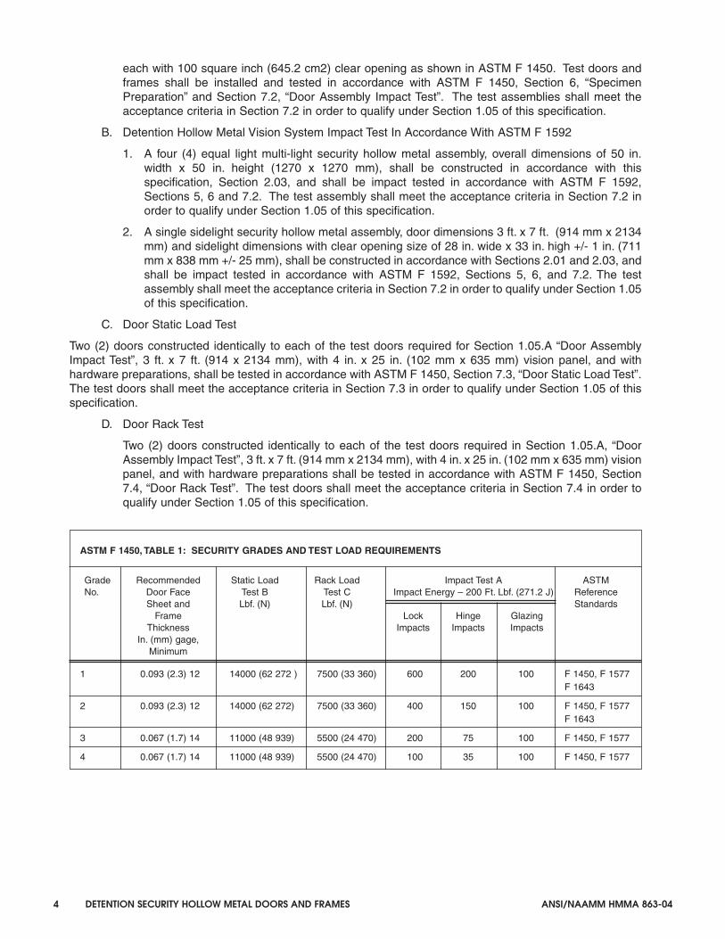
ASTM F 1450, TABLE 1: SECURITY GRADES AND TEST LOAD REQUIREMENTS
Grade Recommended Static Load Rack Load Impact Test A ASTMNo. Door Face Test B Test C Impact Energy – 200 Ft. Lbf. (271.2 J) Reference
Sheet and Lbf. (N) Lbf. (N) StandardsFrame Lock Hinge Glazing
Thickness Impacts Impacts ImpactsIn. (mm) gage,
Minimum
1 0.093 (2.3) 12 14000 (62 272 ) 7500 (33 360) 600 200 100 F 1450, F 1577F 1643
2 0.093 (2.3) 12 14000 (62 272) 7500 (33 360) 400 150 100 F 1450, F 1577F 1643
3 0.067 (1.7) 14 11000 (48 939) 5500 (24 470) 200 75 100 F 1450, F 1577
4 0.067 (1.7) 14 11000 (48 939) 5500 (24 470) 100 35 100 F 1450, F 1577
9511_Body_P12 3/30/05 1:34 PM Page 4

ANSI/NAAMM HMMA 863-04 DETENTION SECURITY HOLLOW METAL DOORS AND FRAMES 5
ASTM F 1592, TABLE 1: IMPACT SERIES FOR FRAME AND GLAZING/PANEL IMPACT TEST MULTILIGHT FRAME
SequenceA Number Number Number Number Impact Energy Location of Blowsof Blows of Blows of Blows of Blows Of Each BlowGrade 1 Grade 2 Grade 3 Grade 4 Ft. Lbf. (J)
Frame1 600 400 200 100 200 (271.2) On the frame joint between the
vertical mullion and the sill orhead (test agent to select at time of test).
2 600 400 200 100 200 (271.2) On the frame joint betweenthe horizontal mullion and the jamb (either side, test agent toselect at time of test).
3 600 400 200 100 200 (271.2) On the frame joint where thevertical and horizontal mullionscross.
4 600 400 200 100 200 (271.2) On the frame joint between thejamb and sill or head (either side,test agent to select at time of test.
Glazing5 600 400 200 100 200 (271.2) On the glazing/panel at the corner
of the glazing/panel within 6 in.(15.2 cm) of the frame stop.Corner selected by the test agentat time of test.
6 600 400 200 100 200 (271.2) On the glazing/panel at the center of the glazing/panel. Glazing/panelto be selected by the test agent attime of test.
CyclicSequence 200 200 100 50
A. The cyclic sequence of impacts will be as indicated by the grade number, and then move to the next sequence number location.If the testing agent observes a location in the assembly where failure is beginning to occur, the testing agent may alter the testsequence to attack the weakened location.
ASTM F 1592, TABLE 2: IMPACT SERIES FOR FRAME AND GLAZING/PANEL IMPACT TEST SIDELIGHT FRAME
SequenceA Number Number Number Number Impact Energy Location of Blowsof Blows of Blows of Blows of Blows Of Each BlowGrade 1 Grade 2 Grade 3 Grade 4 Ft. Lbf. (J)
Frame1 600 400 200 100 200 (271.2) On the frame joint between the
side-light sill and the strike mullion.
2 600 400 200 100 200 (271.2) On the frame joint between thestrike mullion and the header.
Glazing3 600 400 200 100 200 (271.2) On the glazing/panel at the corner
of the glazing/panel closest to thejoint between the side-light sill andthe strike mullion, within 6 in.(15.2cm) of the frame stop.
4 600 400 200 100 200 (271.2) On the glazing/panel at the cornerof the glazing/panel closest to thejoint between the strike mullion and the header within 6 in.(15.2cm) of the frame stop.
5 600 400 200 100 200 (271.2) On the glazing/panel at the centerof the glazing/panel.
CyclicSequence 200 200 100 50
A. The cyclic sequence of impacts will be as indicated by the grade number, and then move to the next sequence number location.If the testing agent observes a location in the assembly where failure is beginning to occur, the testing agent may alter the testsequence to attack the weakened location.
9511_Body_P13 3/30/05 1:34 PM Page 5

6 DETENTION SECURITY HOLLOW METAL DOORS AND FRAMES ANSI/NAAMM HMMA 863-04
E. Door Edge Crush Test
One (1) door constructed identically to either of the test doors required in Section 1.05.A, “DoorAssembly Impact Test”, 3 ft. x 7 ft. (914 x 2134 mm), with 4 in. x 25 in. (102 x 635 mm) visionpanel, and with hardware preparations, shall be tested in accordance with ASTM F 1450,Section 7.7 “Door Edge Crush Test”.
F. Bullet Resistance Test
1. Where specified for individual openings, bullet resistance shall be certified by a materialstesting laboratory acceptable to the Authority Having Jurisdiction (AHJ), and the doors andframes shall bear the laboratory bullet resistance rating labels indicating compliance withthe testing procedure described in UL Standard 752, and consistent with ASTM F 1450,Section 6, “Specimen Preparation” and Section 7.1, “Bullet Penetration”.
The .44 Magnum Revolver is used in this specification becauseit is the most powerful commonly available handgun. Accordingto prison officials, high powered rifles, if any are kept on thepremises, would be securely locked in an armory. Handguns,however, could be obtained in a riot situation or can beconcealed and smuggled into public or secure areas. For thisreason it is recommended that all doors which are indicated onthe door schedule to be bullet resistant be certified for the .44Magnum Revolver.
OR
2. A sample door, frame, and hardware assembly shall be constructed, tested, and certified bya qualified independent testing laboratory in accordance with the test procedure outlined inASTM F 1450, Section 6 “Specimen Preparation” and Section 7.1 “Bullet Penetration”. Inthis case test reports shall include complete descriptions of the test procedure and results.Firearms and ammunition used shall be certified as being correct with respect to bulletcaliber, weight, muzzle velocity, and muzzle energy.
G. Labeled Fire Rated and/or Smoke and Draft Control Doors and Frames
1. Doors, frames, transom frames and side light assemblies provided for openings requiringfire protection, temperature rise, and/or smoke and draft control shall be listed and/orclassified, and shall bear the label of a recognized testing agency having a factoryinspection service. The products shall be tested in accordance with, [ANSI/NFPA-252, orANSI/UL-10B, or CAN4-S104] [ANSI/UL-10C, or UBC 7-2; Part 1] [UL 1784 or UBC 7-2;Part 2, or ANSI/NFPA 105] and shall be constructed as listed and/or classified by arecognized testing agency having a factory inspection service.
2. Window frames shall be provided for those openings requiring fire protection ratings shallbe listed and/or classified, and shall bear the label of a recognized testing agency having afactory inspection service. Such frames shall be tested in accordance with [ANSI/NFPA257 or ANSI/UL 9 or CAN4-S106] [UBC 7-4] and constructed as listed by a recognizedtesting laboratory having a factory inspection service.
UBC 7-2 and UL 10C provide for positive pressure testing to accommodate therequirements of some jurisdictions and should be included only for such jurisdictions.
UL 1784, UBC 7-2; Part 2 and ANSI/NFPA 105 provide for smoke and draft controlassembly testing to accommodate these specific requirements, and should be includedonly when required.
Include CAN4-S104 and CAN4-S106 only for projects requiring conformance withCanadian Building codes.
Doors for certain applications may be provided to meet maximum temperature risecriteria under the test standards cited in Section 1.05.G.1 depending upon jurisdiction.
9511_Body_P14 3/30/05 1:34 PM Page 6

ANSI/NAAMM HMMA 863-04 DETENTION SECURITY HOLLOW METAL DOORS AND FRAMES 7
3. If any door or frame specified by the Architect to be fire-rated cannot qualify for appropriatelabeling because of its design, hardware, or any other reason, the Architect shall be soadvised in the submittal documents or prior to manufacture of the product if hardware,glazing or other options affecting the fire rating are unknown at the time of submittaldocument preparation.
Refer to NAAMM/HMMA 850, “Fire-Rated Hollow Metal Doors and Frames”, foradditional information.
1.06 QUALITY ASSURANCE
A. Manufacturer's Qualification
1. Manufacturer shall provide evidence of having personnel and plant equipment capable offabricating hollow metal door and frame assemblies of the type specified herein.
2. Manufacturer shall provide evidence of having a written quality control system in place.
B. Quality Criteria
1. All door and frame construction shall meet the requirements of Section 1.05 of thesespecifications. Fabricate assemblies in strict accordance with approved submittal drawings.
2. Fabrication methods and product quality shall meet standards set by the Hollow MetalManufacturers Association, HMMA, a Division of the National Association of Architectural MetalManufacturers, NAAMM, as set forth in these specifications.
3. Job Site Door Check
At the owner's option, a door at the job site shall be selected at random and sawed in half orotherwise taken apart as deemed necessary, for verification that construction is in accordancewith these specifications and testing documentation in accordance with Section 1.07.C.1. Themanufacturer shall include the cost of the replacement door in the quotation. If the doorconstruction does not conform to these specifications the non-conforming doors shall berepaired or replaced at the manufacturer's expense.
1.07 SUBMITTALS
A. Submittal Drawings
1. Show door and frame elevations and sections.
2. Show listing of opening descriptions including locations, material thicknesses, and anchors.
3. Show location and details of all openings.
4. Indicate performance grade levels on the submittal as they are shown on the contractdocuments.
B. Samples (if required)
1. Door: 1 ft. x 1 ft. (305 mm x 305 mm) corner section with hinge mortise and reinforcementshowing internal construction.
2. Frame: 1 ft. x 1 ft. (305 mm x 305 mm) corner section showing welding of head to jamb. Includehinge mortise, reinforcement and grout guard in one rabbet, and glazing stop applied asspecified in the opposite rabbet. Glazing stop shall be applied in both head and jamb sectionto show their intersection.
3. All samples submitted shall be of the production type and shall represent in all respects theminimum quality of work to be furnished by the manufacturer. No work represented by thesamples shall be fabricated until the samples are approved, and any degradation of fabricationquality compared to the samples is cause for rejection of the work.
9511_Body_P15 04:11:05 14:30 Page 7

8 DETENTION SECURITY HOLLOW METAL DOORS AND FRAMES ANSI/NAAMM HMMA 863-04
C. Test Report
1. Manufacturer shall submit to the Architect upon request, ten (10) days prior to bid date, anindependent testing laboratory report certifying that door and frame assemblies meet theperformance requirements of Section 1.05 and are constructed in accordance with Sections2.01, 2.02 and 2.03 of these specifications. Test reports shall comply with the reportingrequirements outlined in ASTM F1450 and F1592.
2. The manufacturer shall not proceed with fabrication without receipt of approved submittaldrawings and approved hardware schedules.
The approved submittal drawings and the approved hardware schedules are the versionsthat have been provided to the hollow metal manufacturer at the time of release forfabrication. These drawings and schedules are considered part of the project contractdocuments.
D. Qualifications
1. Manufacturer shall submit to the Architect upon request, ten (10) days prior to bid date, theirqualifications as required by Section 1.06.
PART 2 - PRODUCTS2.01 DETENTION SECURITY HOLLOW METAL DOORS
A. Materials
ANSI and ASTM Standards no longer utilize “gage” to define steel thickness. In thisSpecification, steel is expressed in terms of minimum decimal inch (millimeter) thickness.Dimensions or sizes traditionally expressed in fractional inches are shown in decimal inches(millimeters). HMMA has developed a series of Tables (NAAMM/HMMA-803), included asAppendix 1, to summarize the imperial standards and their corresponding metric values.
1. Doors shall be manufactured of commercial quality, level, cold-rolled steel conforming to ASTMA 1008 / A1008M CS type B or hot-rolled, pickled and oiled steel conforming to ASTM A 1011/ A 1011M CS type B. The steel shall be free of scale, pitting, coil breaks, buckles, waves orother surface blemishes or defects.
2. Interior doors: Face sheets shall be [for Grades 3 and 4; 0.067 in. (1.7 mm)] [for Grades 1 and2; 0.093 in. (2.3 mm)] minimum thickness.
For interior doors subject to corrosive conditions it is recommended that zinc coated steelface sheets, as specified in 2.01.A.3, be used.
3. Exterior Doors: Face sheets shall be [for Grades 3 and 4; 0.067 in. (1.7 mm)] [for Grades 1 and2; 0.093 in. (2.3 mm)] minimum thickness and shall have a zinc coating applied by the hot-dipprocess conforming to ASTM A 653/A 653M Commercial Steel (CS type B), coating designationA60 (ZF180) or G60 (Z180).
4. For severely corrosive conditions and where specified for individual openings, either interior orexterior: Face sheets shall be [0.067 in. (1.7 mm)] [0.093 in. (2.3 mm)] minimum thickness. Facesheets and components shall be stainless steel conforming to ASTM A 666, Type [304] [316].Finishes for steel stiffened stainless steel detention doors shall comply with ANSI/NAAMMHMMA 866, required polish not to exceed #4.
If the Architect determines that zinc coated components for zinc coated face sheets andstainless steel components for stainless steel face sheets are needed in addition to zinccoated or stainless steel face sheets, 2.01.A.3 and 2.01.A.4 are the appropriate locationsto specify that requirement.
B. Construction:
1. All doors shall be of the types, sizes and construction in accordance with these specifications,and shall meet the performance requirements of Section 1.05, where applicable. Alternatematerials and methods of construction which meet the aforementioned performance criteriashall be permitted.
9511_Body_P16 3/30/05 1:34 PM Page 8

ANSI/NAAMM HMMA 863-04 DETENTION SECURITY HOLLOW METAL DOORS AND FRAMES 9
2. Door face sheets shall be joined at their vertical edges by a continuous weld extending the fullheight of the door.
See “Weld, Continuous” and “Welded, Continuously” in the Glossary of Terms for HollowMetal Doors and Frames, ANSI/NAAMM HMMA 801.
3. Minimum nominal door thickness shall be 2 in. (50.8 mm) to accommodate detention hardware.Doors shall be neat in appearance and free from warpage or buckle. Edge bends shall be trueand straight and of minimum radius for the thickness of material used.
4. The door shall be stiffened by continuous vertically formed steel sections which upon assembly,shall span the full thickness of the interior space between door faces. These stiffeners shall be0.042 in. (1.0 mm) minimum thickness, spaced so that the vertical interior webs shall be no morethan 4 in. (102 mm) apart and securely fastened to both face sheets by spot welds spaced amaximum of 3 in. (76 mm) o.c. vertically. Spaces between stiffeners shall be filled withfiberglass or mineral rock wool batt-type material.
An acceptable option shall be a welded-in-place structurally shaped steel core. This core shallhave vertical webs that are spaced not more than 4 in. (102 mm) apart, and which shall spanthe full thickness of the interior space between door face sheets. This core shall extendcontinuously over the inside width and height of the door, and shall be securely fastened to bothface sheets by spot welds spaced a maximum of 3 in. (76 mm) o.c. vertically. Internal hollowspaces shall be filled with fiberglass or mineral rock wool batt-type material.
5. The vertical edges shall be reinforced by a continuous steel channel, not less than 0.123 in. (3.1mm) thickness extending the full height of the door. The top and bottom edges shall be closedwith a continuous steel channel, not less than 0.123 in. (3.1 mm) thickness, spot welded to facesheets a maximum of 4 in. (102 mm) o.c. The closing end channel shall be continuously weldedto the vertical edge reinforcing channel at all four corners producing a fully welded perimeterreinforcing channel.
6. The top end channel shall be fitted with an additional flush closing channel of not less than0.053 in. (1.3 mm) thickness. The flush closing channel shall be welded in place at the cornersand at the center.
a. Where specified, exterior doors shall be sealed at the top closing channel assembly in orderto provide weather resistance.
7. Edge profiles shall be provided on both vertical edges of doors as follows unless hardwaredictates otherwise:
Single acting doors - beveled 1/8 in. (3.1 mm) in 2 in. (50.8 mm) profileSliding doors or equivalent - square profile
8. Hardware reinforcements and preparations:
a. Doors shall be mortised, reinforced, drilled and tapped at the factory for templated hardwareonly, in accordance with the approved hardware schedule and templates provided by thehardware supplier. Where non-templated hardware is to be applied, doors shall bereinforced, with all drilling, tapping, and welding done by others in the field.
b. Minimum material thicknesses for steel hardware reinforcements shall be as follows:
• Full mortise hinges and pivots ......................0.167 in. (4.2 mm)
• Surface applied maximum security hinges ....0.214 in. (5.4 mm)
• Strikes ............................................................0.167 in. (4.2 mm)
• Slide device hanger attachment - per device manufacturer’s recommendations
• Lock fronts, concealed holders, or surface mounted closer ............................0.093 in. (2.3 mm)
• All other surface applied hardware ................0.093 in. (2.3 mm)
9511_Body_P17 3/30/05 1:34 PM Page 9

10 DETENTION SECURITY HOLLOW METAL DOORS AND FRAMES ANSI/NAAMM HMMA 863-04
c. In cases where electrically or electronically operated hardware is required, and whereshown on approved submittal drawings or the approved hardware schedule, hardwareenclosures and/or junction boxes within the door shall be provided, and shall beinterconnected using UL approved 0.5 in. (12 mm) minimum diameter conduit andconnectors. Also, where shown on the approved submittal drawings, junction boxes withaccess plates shall be provided to facilitate the proper installation of wiring. Access platesshall be the same material and thickness as the face sheet and fastened with not less thanfour (4) 1/4 - 20 or 1/4 - 28 tamper resistant security screws, not to exceed 6 in. (152 mm)o.c.
9. Glazing moldings and stops:
a. Where specified or scheduled, doors shall be provided with steel moldings to secure glazingmaterials furnished and installed in the field by others in accordance with glazing sizes andthicknesses shown on contract documents.
b. Fixed glass molding shall be not less than 0.093 in. (2.3 mm), and shall be spot welded to bothface sheets 5.0 in. (127 mm) o.c. maximum.
c. In glass openings where non-security glazing is specified or scheduled, removable glazingstops shall be pressed steel channel not less than 0.067 in. (1.7 mm) thickness with tight fittingbutt or mitered corner joints, and secured with #8-32 countersunk, tamper resistant securityscrews located 2 in. (50.8 mm) maximum from each end and 9 in. (228 mm) o.c. maximum.
d. In glass openings where security glazing is specified or scheduled, and where shown on theapproved submittal drawings, pressed steel angle glazing stops, not less than .093 in. (2.3 mm)thickness, shall be provided. Angle stops shall be mitered or notched and tight fitting at thecorner joints, and secured in place using 1/4 - 20 or 1/4 - 28 button head tamper resistantsecurity screws spaced 2 in. (50.8 mm) maximum from each end and 6 in. (152 mm) o.c.maximum. The glazing stop system shall satisfy the performance criteria in Section 1.05.B.
It is recommended that view window stop heights be specified to provide 1 in. (25.4 mm)glass engagement.
Advisory: It is not advisable to locate glass preparations in close proximity to hardwarepreparations at the door edge, since this can be detrimental to door stiffness.
e. Metal surfaces to which glazing stops are secured shall be treated for maximum paint adhesionand painted with a rust inhibitive primer. The inside of the glazing stops shall be treated formaximum paint adhesion and painted with a rust inhibitive primer, or shall be fabricated fromzinc coated steel pursuant to 2.01.A.3.
10. Louvers shall be of the welded inverted “V”or “Y” type construction providing free air delivery asspecified. The louver opening shall be flush, fabricated using interior channels 0.093 in. (2.3 mm)minimum thickness, securely welded to the inside of both face sheets. Rectangular louversexceeding 18 in. (457 mm) in width shall be reinforced at their midpoints by a vertical rectangularsteel bar at least 0.25 in. x 1.50 in. (6.4 mm x 38 mm) or a vertical round steel bar at least 0.75 in.(19 mm) diameter. The vanes shall be not less than 0.093 in. (2.3 mm) thickness and shall bespaced so that no rigid flat instrument can be passed through them. Insect screens and flattenedexpanded metal not less than 0.093 in. (2.3 mm) thickness shall be provided on louvered doors inexterior locations where shown on contract documents. Louvers of other designs which meet theperformance requirements in Section 1.05.A, “Door Impact Test”, can be qualified for thisapplication.
11. Speaking devices shall consist of a rectangular pattern of round holes, no more than 0.25 in. (6.3mm) dia., in both face sheets directly across from each other. The minimum size of the rectangularhole pattern shall be 1 in. (25 mm) high x 4 in. (101 mm) wide with holes spaced no more than 1 in.(25 mm) o.c. vertically and horizontally. The interior of the door between the rectangular holepatterns shall be baffled using pressed steel sections, not less than 0.067 in. (1.7 mm), so that noobjects can be passed through.
9511_Body_P18 3/30/05 1:34 PM Page 10

ANSI/NAAMM HMMA 863-04 DETENTION SECURITY HOLLOW METAL DOORS AND FRAMES 11
12. Food Pass / Cuff Port Openings:
a. The food pass opening shall be a flush opening fabricated using interior channels 0.093 in. (2.3mm) minimum thickness, securely welded to both face sheets. The four corner seams shall becontinuously arc welded and dressed smooth. The finished opening shall be of suchconstruction that it cannot be dismantled or otherwise affected by tampering or scraping.
b. The food pass shutter shall be constructed from two 0.123 in. (3.1 mm) thickness steel platesspot welded together to produce an inset fit that, when closed, will prevent tampering with thelock and hinges.
c. The shutters shall be treated for maximum paint adhesion and given a shop coat of rustinhibitive primer. They shall be shipped loose for installation in the field by others.
2.02 DETENTION SECURITY HOLLOW METAL PANELS
A. Hollow metal panels shall be made of the same materials and construction and finished in the sameway as specified in Sections 2.01 and 2.06.
B. Hollow metal panels shall meet performance criteria set forth in Section 1.05.B of this Specification.
2.03 DETENTION SECURITY HOLLOW METAL FRAMES
A. Materials
1. Frames shall be constructed from cold rolled steel conforming to ASTM A 1008 / A1008M CSType B, or hot rolled, pickled and oiled (HRPO) steel conforming to ASTM A 1011 / A 1011MCS Type B. The steel shall be free of scale, pitting, coil breaks or other surface defects.
2. Interior openings: Frame sections shall be [for Grades 3 and 4; 0.067 in. (1.7 mm)] [for Grades1 and 2; 0.093 in. (2.3 mm)] minimum thickness.
For interior areas subject to corrosive conditions it is recommended that zinc coated framesas specified in 2.03 A.3 be used.
3. Exterior openings: Frame sections shall be [for Grades 3 and 4; 0.067 in. (1.7 mm)] [for Grades1 and 2; 0.093 in. (2.3 mm)] minimum thickness and shall have a zinc coating applied by the hot-dip process conforming to ASTM A 653/A 653M Commercial Steel (CS Type B), coatingdesignation A60 (ZF180) or G60 (Z180).
4. Where specified for severely corrosive conditions and where specified for individual openings,either interior or exterior: Frame sections shall be [0.067 in. (1.7 mm)] [0.093 in. (2.3 mm)]minimum thickness. Frame sections and components shall be stainless steel conforming toASTM A 666, Type [304] [316]. Finishes for stainless steel detention frames shall comply withANSI/NAAMM HMMA 866, required polish not to exceed #4.
B. Construction:
1. All frames, with the exception of cased openings such as for sliding doors, shall have integralstops and be welded units of the sizes and types shown on approved submittal drawings.Frames shall be constructed in accordance with these specifications and shall meetperformance criteria specified in Sections 1.05.A and 1.05.B where applicable. Alternatematerials and methods of construction which meet the aforementioned performance criteriashall be permitted.
2. Finished work shall be neat in appearance, square, and free of defects, warps and buckles.Pressed steel members shall be straight and of uniform profile throughout their lengths.
3. Jamb, header, mullion and sill profiles shall be in accordance with the frame schedule and asshown on the approved submittal drawings.
4. Corner joints shall have all contact edges closed tight with faces mitered and stops either buttedor mitered. Corner joints shall be continuously welded and the use of gussets or splice platesare not acceptable.
For detailed information on continuously welded corner joints, see Tech Note HMMA-820TN02-03.
9511_Body_P19 3/30/05 1:34 PM Page 11

12 DETENTION SECURITY HOLLOW METAL DOORS AND FRAMES ANSI/NAAMM HMMA 863-04
5. All other face joints shall be continuously welded and finished smooth.
6. Minimum height of stops in door openings shall be 0.625 in. (15.8 mm). Height of stops onsecurity glazing or panel openings shall be as shown on approved submittal drawings. Cut-offstops, where specified shall be capped at 45 degrees or 90 degrees at heights as shown onapproved submittal drawings, and jamb joints below cut-off stops shall be tight fitting, weldedand ground smooth so that there are no visible seams.
In some applications, 3/4 in. (19 mm) frame stops are used with 2 in. (50.8 mm) thick doors.
7. When shipping limitations or site access so dictate, or when advised by the contractorresponsible for installation, frames for large openings shall be fabricated in sections designatedfor assembly in the field by others. Alignment plates or angles shall be installed at each joint.Such components shall be the same material and thickness as the frame. Field joints shall bemade in accordance with approved submittal drawings, and shall be field welded by others.
8. Frames for multiple openings shall have mullion members which, after fabrication, are closedtubular shapes conforming to profiles shown on approved submittal drawings, and having noexposed visible seams or joints. All joints between faces of abutted members shall becontinuously welded and finished smooth. All joints between stops of abutted members shallbe welded along the soffit and shall be left neat and uniform in appearance. The contractorresponsible for installation shall provide for welding and finishing all field joints between facesof abutted members.
9. Hardware Reinforcements and Preparation:
a. Frames shall be mortised, reinforced, drilled and tapped at the factory for all templatedhardware only, in accordance with the final approved hardware schedule and templatesprovided by the hardware supplier. Where non-templated hardware is to be applied, frames shallbe reinforced with all drilling, tapping and welding done by others in the field.
b. Minimum material thickness of steel hardware reinforcements shall be as follows:
Hinges and pivots ......................................0.167 in. x 1.5 in. x 10 in. length(4.2 mm x 38 mm x 254 mm)
Strikes ........................................................0.167 in. (4.2 mm)
Closers ......................................................0.167 in. (4.2 mm)
Flush bolts ..................................................0.167 in. (4.2 mm)
All other surface applied hardware ............0.093 in. (2.3 mm)
c. In cases where electrically or electronically operated hardware is required, and where shown onapproved submittal drawings or approved hardware schedule, hardware enclosures andjunction boxes shall be provided, and shall be interconnected using UL approved 0.5 in. (12 mm)diameter minimum conduit and connectors. Where shown on contract documents junction boxeswith access plates shall be provided to facilitate the proper installation of wiring. Access platesshall be the same material and thickness as the frame and fastened with not less than four (4)1/4-20 or 1/4-28 tamper resistant security screws, not to exceed 6 in. (152 mm) o.c.
10. Floor Anchors:
a. Where applicable, floor anchors shall be provided with two (2) holes for fasteners and shall befastened inside jambs with at least four (4) spot welds per anchor.
b. Where so scheduled, adjustable floor anchors, providing not less than 2 in. (50.8 mm) heightadjustment, shall be fastened in place with at least four (4) spot welds per anchor.
c. Thickness of floor anchors shall be the same as frame.
11. Jamb Anchors:
a. Anchor Spacing
9511_Body_P20 3/30/05 1:34 PM Page 12

ANSI/NAAMM HMMA 863-04 DETENTION SECURITY HOLLOW METAL DOORS AND FRAMES 13
The number of anchors provided on each jamb shall be as follows:
Borrowed lite frames 2 anchors plus 1 for each 18 in. (457 mm) or fraction thereof over 36in. (914 mm), spaced at 18 in. (457 mm) maximum between anchors
Door frames 2 anchors plus 1 for each 18 in. (457 mm) or fraction thereof over 54in. (1372 mm), spaced at 18 in. (457 mm) maximum between anchors(fire ratings can require additional anchors)
b. Masonry Type
Frames for installation in masonry walls shall be provided with adjustable jamb anchors of thestrap and stirrup type made from the same thickness steel as frame. Straps shall be no lessthan 2 in. x 10 in. (50.8 mm x 254 mm) in size, corrugated and/or perforated.
c. Embedment Masonry Type
1. Frames for installation in pre-finished masonry or concrete openings shall be provided withremovable faces at the jambs, and 0.187 in. x 2 in. x 2 in. (4.7 mm x 50.8 mm x 50.8 mm)angle anchors 4 in. (102 mm) long spaced as described in Section 2.03.B.10.a. The frameanchors shall be located to coincide with matching embedded anchors to be provided forinstallation in the wall.
2. Embedded wall anchors shall consist of a 0.187 in. x 4 in. wide x 6 in. long (4.7 mm x 102mm wide x 152 mm long) plate with 0.187 in. x 2 in. x 2 in. (4.7 mm x 50.8 mm x 50.8 mm)angle anchors 4 in. (102 mm) long welded in place at locations to match angle anchors inframes. The embedded plate shall be provided with two (2) #4 re-bar wall anchors 10 in.(254 mm) long minimum, with 2 in. (50.8 mm) x 90 degree turn down on ends continuouslywelded in place, and spaced as described in Paragraph 2.03.B.10.a. Embedments shall beprime painted in accordance with Section 2.06.
3. Angle anchors shall each be fastened to jamb and to embedded plate with two (2) 1 in. (25.4mm) long arc welds at each end of the anchor. Anchors shall be shipped loose.
4. The complete anchorage system shall provide that the jamb faces be removed from theframes in the field by the contractor responsible for installation, and the frames be movedinto the opening. Using the 0.187 in. x 2 in. x 2 in. x 4 in. (4.7 mm x 50.8 mm x 50.8 mm x102 mm) long angles, the installer shall weld one edge of the angle to the embedded anchorand the other edge to the frame mounted anchor forming a rigid connection between theframe and the embedded plate. The procedure shall be repeated for all anchor positions.The installer shall field weld all anchors and install the jamb faces in place. Embedmentanchoring details shall be provided on approved submittal drawings.
d. Expansion Bolt Type
1. Frames for installation in existing masonry or concrete walls shall be prepared for expansionbolt type anchors. The preparation shall consist of a countersunk hole for a 0.5 in. (12.7mm) diameter bolt and a conduit spacer from the unexposed surface of the frame to the wallwelded within the jamb profile. The preparation shall be spaced as described in Section2.03.B.10.a. Fasteners for such anchors shall be provided by others.
2. After sufficient tightening of the bolt, the bolt head shall be welded by the installationcontractor so as to provide a non-removable condition. The welded bolt head shall beground, dressed and finished smooth.
e. Frames to be installed in pre-finished concrete, masonry or steel openings, shall be constructed andprovided with anchoring systems of suitable design as shown on the approved submittal drawings.
9511_Body_P21 3/30/05 1:34 PM Page 13

14 DETENTION SECURITY HOLLOW METAL DOORS AND FRAMES ANSI/NAAMM HMMA 863-04
12. Grout guards shall be provided at all hardware preparations, glazing stop screws and silencerpreparations on frames to be set in masonry or concrete openings. Grout guards shall be sufficient toprotect preparations from grout of a 4 in. (102 mm) maximum slump consistency which is hand troweledin place. If pump grout that exhibits slump values of higher than 4 in. (102 mm) is used, additionalprecautions shall be taken in the field by the contractor to seal grout guards to prevent leakage and tobrace frame sections to prevent deformation. (Ref. HMMA-820 TN01-03, “Grouting of Hollow MetalFrames”)
a. Grout guards for glazing stop screws shall be factory installed and shall cover the exposedportion of the screws inside the frame throat, around the perimeter. Where mullions are requiredto be grouted, screws inside mullions shall be protected with grout guards.
b. Silencer preparations shall be protected by steel grout guards where accessible from the framethroat. Silencers shall be furnished and installed by the contractor responsible for frameinstallation except where limited access prevents installation of the metal grout guards inmullions, in which cases silencers shall be factory furnished and installed.
For detailed information on grouting of hollow metal frames, see Tech Note HMMA-820 TN01-03.
13. All door openings shall be provided with two (2) temporary steel spreaders welded to the bottom ofthe jambs or mullions to serve as bracing during shipping and handling. The installation contractorshall be responsible for finishing and touch-up of marks caused by spreader removal.
14. Removable glazing stops:
a. In openings where non-security glazing is specified, loose channel type glazing stops shall becold rolled steel, not less than 0.067 in. (1.7 mm) thickness, butted at corner joints and securedto the frame using #8-32 countersunk tamper resistant security screws, spaced 2 in. (50.8 mm)maximum from each end and 9 in. (228 mm) o.c. maximum.
b. In openings where security glazing is specified and where shown on the approved submittaldrawings, pressed steel angle glazing stops, not less than 0.093 in. (2.3 mm) thick, shall beprovided. Angle stops shall be mitered or butted and tight fitting at the corner joints, andsecured in place using 1/4 - 20 or 1/4 - 28 tamper resistant security screws spaced 2 in. (50.8mm) maximum from each end and 6 in. (152 mm) o.c. maximum. The glazing stop system shallsatisfy the performance criteria in Section 1.05.B.
It is recommended that view window stop heights be specified to provide 1 in. (25.4 mm)glass engagement.
c. The frame section underneath the glazing stops shall be treated for maximum paint adhesionand painted with a rust inhibitive primer. The inside of the glazing stops shall be treated formaximum paint adhesion and painted with a rust inhibitive primer, or shall be fabricated fromzinc coated steel pursuant to Section 2.03.A.3.
2.04 MANUFACTURING TOLERANCES
The manufacturer of the doors and frames is responsible only for the manufacturing toleranceslisted in Section 2.04. The final clearances and relationships between door and frame depends onthe setting of the frame and the hanging and adjustment of the door and hardware. (See Sections3.02 and 3.03).
A. Manufacturing tolerance shall be maintained within the following limits:
1. Frames for single doors or pairs of doors:
a. Width, measured between rabbets at the head: Nominal opening width + 1/16 in.(1.6 mm),- 1/32 in. (0.8 mm).
b. Height (total length of jamb rabbet): Nominal opening height +/- 3/64 in. (1.2 mm).
9511_Body_P22 3/30/05 1:34 PM Page 14

ANSI/NAAMM HMMA 863-04 DETENTION SECURITY HOLLOW METAL DOORS AND FRAMES 15
2. Cross sectional profile dimensions (see Figure 4):
a. Face............................................................+/- 1/32 in. (0.8 mm)
b. Stop ............................................................+/- 1/32 in. (0.8 mm)
c. Rabbet ........................................................+/- 1/32 in. (0.8 mm)
d. Depth ..........................................................+/- 1/32 in. (0.8 mm)
e. Throat ........................................................+/- 1/16 in. (1.6 mm)
Frames overlapping walls to have throat dimension 1/8 in. (3.1mm) greater than wall thickness to accommodate irregularities inwall construction.
3. Flatness of large frames ..................................1/8 in (3.1 mm) in 10 ft (3048 mm) of length orwidth
4. Doors Tolerance on actual door sizes are as follows:
a. Width ..........................................................+/- 3/64 in. (1.2 mm)
b. Height ........................................................+/- 3/64 in. (1.2 mm)
c. Thickness ..................................................+/- 1/16 in. (1.5 mm)
d. Bow/flatness ..............................................+/- 1/16 in. (1.5 mm) in 7 ft. (2134 mm)
Doors are undersized to fit the frame. Edge clearances arebased upon individual door manufacturer’s designs.
FRAME DEPTH+/- 1/32 IN. (0.8MM)
THROAT OPENING+/- 1/16 IN. (1.5MM)
RABBET+/- 1/32 IN. (0.8MM)
STOP+/- 1/32 IN. (0.8MM)
FACE+/- 1/32 IN. (0.8MM)
SOFFIT
RETURN
FIGURE 4
9511_Body_P23 3/30/05 1:34 PM Page 15

16 DETENTION SECURITY HOLLOW METAL DOORS AND FRAMES ANSI/NAAMM HMMA 863-04
5. Hardware
a. Cutout and template dimensions................+ 0.015 in. (0.38 mm) - 0 in.
b. Location ......................................................+/- 1/32 in. (0.8 mm)
c. Between Hinge Centerlines........................+/- 1/64 in. (0.4 mm)
2.05 HARDWARE LOCATIONS
The location of hardware on doors and frames shall be as listed below. Note that all dimensions exceptthe hinge locations are referenced from the finished floor as defined in Section 3.03.
A. Hinges:
Top....................................5 in. (127 mm) from frame head rabbet at door opening to top of hinge
Bottom ..............................10 in. (254 mm) from floor to bottom of hinge
Intermediate......................equally spaced between top and bottom hinges
B. Locks and latches ..................38 in. (965 mm) to centerline of knob or lever shaft
C. Deadlocks ..............................46 in. (1168 mm) to centerline of cylinder
D. Exit hardware ..........................38 in. (965 mm) to centerline of cross bar or as shown onhardware template
E. Door pulls................................42 in. (1066 mm) to centerline of grip
F. Push/pull bars ........................42 in. (1066 mm) to centerline of bar
G. Arm pulls ................................46 in. (1168 mm) to centerline
H. Push plates ............................46 in. (1168 mm) to centerline of plate
I. Intercoms ................................48 in. (1219 mm) to centerline of intercom push button
2.06 FINISH
After fabrication, all tool marks and surface imperfections shall be filled and sanded as required to makeface sheets, vertical edges and weld joints free from irregularities. After appropriate metal preparation,all exposed surfaces of doors and frames shall receive a rust inhibitive primer, which meets or exceedsANSI A 250.10, “Test Procedures and Acceptance Criteria for Prime Painting Steel Surfaces for SteelDoors and Frames”. For stainless steel finishes refer to ANSI/NAAMM/HMMA 866.
All primer and finish paint must be formulated for Direct to Metal(DTM) application.
PART 3 - EXECUTIONNote to Architect: Proper storage and protection is essential to theproper performance of doors and frames. The requirements for properstorage are given in the following sections. However, it is important torecognize that proper storage is not the responsibility of the hollowmetal manufacturer. For this reason, the requirements for storage andprotection of detention hollow metal doors and frames shall bereferenced in that section of the specifications where installation of workis specified. (Reference: HMMA 840 “Installation and Storage of HollowMetal Doors and Frames”).
9511_Body_P24 3/30/05 1:34 PM Page 16

ANSI/NAAMM HMMA 863-04 DETENTION SECURITY HOLLOW METAL DOORS AND FRAMES 17
3.01 SITE STORAGE AND PROTECTION OF MATERIALS
A. The contractor responsible for installation shall remove wraps or covers from doors and frames upondelivery at the building site. The contractor responsible for installation shall ensure that anyscratches or disfigurement caused in shipping or handling are promptly sanded smooth, cleanedand touched up with a compatible rust inhibitive Direct to Metal (DTM) primer.
B. The contractor responsible for installation shall ensure that materials are properly stored on planksor dunnage in a dry location. Doors and frames shall be stored in a vertical position and spaced byblocking. Figure 5 illustrates recommended storage positioning. Materials shall be covered toprotect them from damage but in such a manner as to permit air circulation.
3.02 INSTALLATION
Note to Architect: Correct installation is essential to the properperformance of detention doors and frames. The requirements for properinstallation are given in the following sections. However, it is important torecognize that installation is not the responsibility of the detention hollowmetal manufacturer. For this reason, the requirements for installation ofdetention hollow metal doors and frames shall be referenced in thatsection of the specifications where installation of work is specified. It isthe responsibility of the general contractor using experienced personnelto perform the work outlined in this section. (Reference: HMMA 840“Installation and Storage of Hollow Metal Doors and Frames”)
The Contractor responsible for installation shall perform the following:
A. Prior to installation, all frames shall be checked for correct size, and swing, and with temporaryspreaders removed, corrected for squareness, alignment, twist and plumb. Permissible installationtolerances shall not exceed 1/16 in. (1.5 mm):
Squareness ..........................measured at rabbet on a line from jamb, perpendicular to frame head.
WOODPLANKING
WOODPLANKING
FIGURE 5Recommended Storage
WOODPLANKING
WOODPLANKING
9511_Body_P25 3/30/05 1:34 PM Page 17

18 DETENTION SECURITY HOLLOW METAL DOORS AND FRAMES ANSI/NAAMM HMMA 863-04
Alignment ............................measured at jambs on a horizontal line parallel to the plane of the face.
Twist ....................................measured at opposite face corners of jambs on parallel lines,perpendicular to the plane of the door rabbet.
Plumbness ..........................measured at jambs on a perpendicular line from the head to the floor.
During the setting of the frames, check and maintain these tolerances for squareness, alignment ,twist and plumbness.
The details in Figure 6 illustrate methods of measuring the above specified tolerances.
The above tolerances provide a reasonable guideline for properinstallation of hollow metal frames. However, it should be noted that thecumulative affect of the installation tolerances at or near their maximumlevels could result in sufficient misalignment to prevent the door fromfunctioning properly. Installers should be careful not to create aninstallation tolerance buildup. Tolerance buildup occurs when severaldimensions are at or near their maximum tolerance.
90°
MAXIMUM TOLERANCE 1/16 IN. (1.5MM)
90°
SQUARENESS; MEASURED ATRABBET ON A LINE FROMJAMB PERPENDICULARTO FRAME HEAD.
PLUMBNESS; MEASURED ATJAMBS ON A PERPENDICULARLINE FROM THE HEAD TO THEFLOOR.
ALIGNMENT; MEASURED ATJAMBS ON A HORIZONTALLINE PARALLEL TO THEPLANE OF THE FACE.
TWIST; MEASURED AT OPPOSITE FACECORNERS OF JAMBS ON PARALLELLINES, PERPENDICULAR TO THE PLANEOF THE DOOR RABBET.
PROFILE MAY VARYAS A FUNCTIONALDESIGN
MAXIMUM TOLERANCE1/16 IN. (1.5MM)
HINGE ORSTRIKE JAMB
HEAD
FIGURE 6Installation Tolerances
9511_Body_P26 3/30/05 1:34 PM Page 18

ANSI/NAAMM HMMA 863-04 DETENTION SECURITY HOLLOW METAL DOORS AND FRAMES 19
B. Frame jambs shall be fully grouted to provide added security protection against battering, wedging,spreading and other means of forcing open the door. Jamb mounted lock preparations, grout guardsfor hardware preparations and glazing stop screws, and junction boxes are intended to protecthardware mortises, exposed removable screws, and tapped mounting holes from masonry grout of4 in. (102 mm) maximum slump consistency which is hand troweled in place. If a light consistencygrout (greater than 4 in. (102 mm) slump in accordance with ASTM C 143 / C 143M) is to be used,special precautions shall be taken in the field by the installation contractor to protect tapped holes,electrical knock-outs, lock pockets, grout guards, junction boxes, etc. in the frames.
Large frame sections, such as lock columns and lock jambs, are not intended or designed to act asforms for grout or concrete. Grouting of large hollow metal sections shall be done in “lifts” orprecautions shall be otherwise taken by the contractor to insure that frames are not deformed ordamaged by the hydraulic forces that occur during this process.
The drawbacks and benefits associated with the use of water based masonry grouts, with or withoutantifreeze agents, should be carefully weighed during the detailing and specification process.Plaster based grouts should not be used under any circumstances. Refer to NAAMM’s HMMATechNotes HMMA-820 TN01-03, “Grouting Hollow Metal Frames”, in Appendix 2 for furtherguidance.
C. Proper door clearances shall be maintained in accordance with 3.03 of these specifications, exceptfor special conditions otherwise noted. Where necessary, metal hinge shims, furnished by theContractor responsible for installation, are acceptable to maintain clearances.
D. Hardware shall be applied in accordance with hardware manufacturer's templates and instructions.
E. Any grout or other bonding material shall be cleaned off of frames or doors immediately followinginstallation. Exposed hollow metal surfaces shall be kept free of grout, tar, or other bonding materialor sealer.
F. Exposed field welds shall be finished smooth and touched up with a rust inhibitive primer.
G. Primed or painted surfaces which have been scratched or otherwise marred during installation,cleaning, and/or field welding, including marks caused by spreader removal, shall promptly befinished smooth, cleaned, treated for maximum paint adhesion and touched up with a rust inhibitiveDirect to Metal (DTM) primer comparable to and compatible with the shop applied primer and finishpaint specified in Section 09900 [09 90 00]. All touch-up primer and finish paint must be formulatedfor DTM application.
H. Finish paint in accordance with Section 09900 [09 90 00].
I. Install door silencers.
J. Install glazing materials in accordance with Section 08800 (or 11190 [08 88 53]).
3.03 CLEARANCES
A. Edge clearances for swinging doors shall provide for the functional operation of the assembly andshall not exceed the following:
1. Between doors and frames at head and jambs: 3/16 in. (4.7 mm)
2. Between edges of pairs of doors: 3/16 in. (4.7 mm)
3. At doorsills where a threshold is used: 3/8 in. (9.5 mm)
4. At doorsills where no threshold is used: 3/4 in. (19.1 mm)
5. Between door bottom and nominal surface of floor coverings at fire rated openings as providedin ANSI/NFPA 80, 1/2 in. (12.7 mm).
B. Clearances for detention sliding doors shall be in accordance with the approved slider devicedrawings furnished as part of the approved hardware schedule.
9511_Body_P27 3/30/05 1:34 PM Page 19

20 DETENTION SECURITY HOLLOW METAL DOORS AND FRAMES ANSI/NAAMM HMMA 863-04
Floor is defined as the top of the concrete slab or structural floor. Whereresilient tile, hardwood or other floor coverings are used, undercutsmust be increased in order to accommodate those floor coverings. TheArchitect must define the distance from the top of the floor/finished floorto the top of the floor covering so that appropriate undercuts can beprovided. Refer to NAAMM’s HMMA TechNotes HMMA-810 TN01-03,“Defining Undercuts”, in Appendix 3.
The final clearances and relationship between door and frame dependsupon the setting of the frame and hanging and adjusting of the door andhardware. If everything is perfect in the setting of the frame, and themanufacturing of the doors and frames, the clearances should be asshown in 3.03. However, if the frame is set to its maximum allowabletolerances, and the doors and frames are manufactured to theirmaximum allowable tolerances, the clearances could be greater.
All clearances are subject to change depending upon the requirementsof the specified hardware.
9511_Body_P28 3/30/05 1:34 PM Page 20

ANSI/NAAMM HMMA 863-04 DETENTION SECURITY HOLLOW METAL DOORS AND FRAMES A-1
APPENDIX(Not part of the Standard)
NAAMM HMMA 803 STEEL TABLESPrior to 1970, sheet steel was referred to by gage. ASTM and ANSI currently do not list gage numbers in theirstandards. Like many generic terms, gage (or gauge) is ingrained in many vocabularies and is misunderstoodas a term for thickness. NAAMM is publishing this minimum thickness table to be used instead of discontinuedgage numbers.
The values shown were taken from the Underwriters Laboratories, Inc. publication for gage number andequivalent thickness.
DISCLAIMER
This sheet was developed by representative members of the Hollow Metal Manufacturers Association Division(HMMA) of the National Association of Architectural Metal Manufacturers (NAAMM) to provide their opinionand guidance on minimum thickness and metric equivalents used for hollow metal doors and frames. Thissheet contains advisory information only and is published as a public service by the HMMA Division. NAAMMand its HMMA DIVISION DISCLAIM ALL LIABILITY OF ANY KIND FOR THE USE, APPLICATION ORADAPTATION OF MATERIAL SHOWN ON THIS SHEET,
HMMA Hollow Metal Manufacturers Division of the
National Association of Architectural Metal Manufacturers NAAMM
MINIMUM THICKNESSUncoated Steel Sheet
Gage Decimal mm
4 0.214 5.4
5 0.199 5.0
6 0.184 4.6
7 0.167 4.2
8 0.152 3.8
10 0.123 3.1
12 0.093 2.3
14 0.067 1.7
16 0.053 1.3
18 0.042 1.0
20 0.032 0.8
22 0.026 0.6
24 0.020 0.5
26 0.016 0.4
28 0.013 0.3
CONVERSIONFraction Decimal mm
1.000 25.4
15/16 0.937 23.8
7/8 0.875 22.2
13/16 0.812 20.6
3/4 0.750 19.0
11/16 0.687 17.4
5/8 0.625 15.8
9/16 0.562 14.2
1/2 0.500 12.7
7/16 0.437 11.1
3/8 0.375 9.5
5/16 0.312 7.9
1/4 0.250 6.3
3/16 0.187 4.7
1/8 0.125 3.1
1/16 0.062 1.5
9511_Body_P29 3/30/05 1:34 PM Page 21

A-2 DETENTION SECURITY HOLLOW METAL DOORS AND FRAMES ANSI/NAAMM HMMA 863-04
GROUTING HOLLOW METAL FRAMES
Grout, when used in accordance with industry guidelines, can improve frame durability, sound deadening,and, depending on wall construction, increase frame anchorage strength. Grouting of the frame does notincrease door durability, nor is it required for fire-rated frames. For most commercial applications, grouting ofmullions and other closed sections is not recommended.
For applications covered by ANSI/NAAMM HMMA 862, “Guide Specifications for Commercial SecurityHollow Metal Doors and Frames,” and ANSI/NAAMM HMMA 863, “Guide Specifications for DetentionSecurity Hollow Metal Doors and Frames,” the standards require that “frame jambs shall be fully grouted toprovide added security protection against battering, wedging, spreading, and other means of forcing openthe door”.
Grout is a water-based product. If not used properly, it can destroy the opening in a very short time. Groutcan be either “mortar”, which is a masonry mixture of lime, cement, sand, and water, or “plaster”, which is agypsum-based product.
Plaster grout dries by exposure to air. When a frame member is filled solid with plaster grout, only thoseareas exposed to air will dry and harden, while the center remains wet (uncured). The water remaining inthe plaster grout can rust the frame from the inside. Plaster grout should not be used.
Mortar grout cures by chemical reaction and hardens throughout. Use mortar grout.
Frames are not designed to act as forms for grout. Grout must have a maximum 4 in. slump and be handtroweled in place. Bracing of the frame may be necessary prior to grouting to prevent sagging of the headeror bowing of the jamb due to weight or pressure of the grout. Grout should not be installed after gypsumwallboard is installed, as the liquid within the grout will deteriorate the wallboard.
When dictated by temperatures, anti-freezing agents for mortar may be recommended by specifications.These agents can adversely affect metal, and all surfaces in contact with the grout must be coated with acorrosion resistant material.
It is recommended that the contractor be responsible for the grouting and for any required barrier coating. Itis also his responsibility to use care in the application of the grout.
9511_Body_P30 3/30/05 1:34 PM Page 22

ANSI/NAAMM HMMA 863-04 DETENTION SECURITY HOLLOW METAL DOORS AND FRAMES A-3
DEFINING UNDERCUTS
Review of established definitions.
1. “ACTUAL DOOR HEIGHT” – The door open-ing height minus top clearance and undercut.
2. “DOOR OPENING HEIGHT” – The distancemeasured vertically between the frame headrabbet and top of floor or bottom of frameminus jamb extension.
3. “FINISHED FLOOR” – See “Floor”
4. “FLOOR” – The top of the concrete orstructural slab.
5. “FLOOR CLEARANCE” – The distancebetween the bottom of the door and the top ofthe material directly below the door. Thisvaries with application, such as concrete, anyfloor covering and/or a threshold.
6. “FLOOR COVERING” – Any material appliedon top of the floor that extends under the doorin its closed position or under the door as itswings to its fully open position.
7. “UNDERCUT” – The distance between thebottom of door and the bottom of frame. Theformula in which to determine Undercut isderived by adding the total sum of thefollowing (Floor Clearance + Floor CoveringThickness + Threshold Height (assuming thethreshold is mounted on top of the floorcovering) + Jamb Extensions Height.
8. “JAMB EXTENSIONS” – That portion of ajamb or mullion which extends below the levelof the floor.
Typically frames are intended to be installeddirectly on the floor. When no floor coverings orthresholds are used, the dimension for“Undercut” is the same as for “Floor Clearance.”See Figure #1.
Floor coverings, such as carpet, resilient orceramic tile, are typically installed on top of thefloor, fitted around the frame, and under thedoor. In this situation, the formula for figuringUndercut is the total of the Floor Clearance +Floor Covering Thickness. See Figure #2.
When a threshold is used, it is installed on topof the floor or floor covering, fitted around theframe and under the door. Again the formula forfiguring “Undercut” changes. Undercut is thetotal of the
AC
TU
AL
DO
OR
HE
IGH
T
BOTTOMOF FRAME
DO
OR
OP
EN
ING
HE
IGH
T
Figure #1
CLEARANCE
FLOOR
UNDERCUT,FLOOR CLEARANCE
FLOOR
FLOOR CLEARANCE
Figure #2
AC
TU
AL
DO
OR
HE
IGH
T
FLOORD
OO
R O
PE
NIN
G H
EIG
HT
BOTTOMOF FRAME
UNDERCUT
FLOORCOVERING
9511_Body_P31 04:12:05 9:33 Page 23

A-4 DETENTION SECURITY HOLLOW METAL DOORS AND FRAMES ANSI/NAAMM HMMA 863-04
Floor Clearance + Threshold Height + FloorCovering Thickness. See Figure #3.
In situations with specialized floors such as thickceramic tile or terrazzo, the frame is typicallyinstalled prior to the installation of the floor.
One method is to install the frame withadjustable floor anchors or for the frame to beinstalled on a block or shim. This allows theframe to be positioned, as required, toaccommodate the floor height. See Figures #4Aand #4B. Both illustrate a raised frame conditionin which the bottom of frame is positioned to bedirectly on top of the floor after the floor isinstalled. In this situation, the dimensionmeasured for Undercut is also the same asFloor Clearance.
Another method, called “below floor installation,”is to install the frame directly on the rough slab.After the frame is installed, the floor is theninstalled around the frame. That portion of the
frame that is covered by the floor is called jambextensions. The formula for figuring “Undercut” isthe total of the Floor Clearance + JambExtensions. See Figure #5A and #5B.
The Architect/Designer must be very specificwithin specifications and contract drawings,which should include detailed drawingsillustrating conditions for each floor, includingthicknesses and materials. These drawingsshould designate the height at which the hollowmetal frame should be set. Thresholds andhardware items requiring specific floorclearances shall be listed in the hardwareschedule, which allows the door and framemanufacturer to properly size each opening.
Within the door and frame industry, both theHollow Metal Manufacturers Association(HMMA) a division of the National Association ofArchitectural Metal Manufacturers (NAAMM) andthe Steel Door Institute (SDI), publishrecommended clearances. In addition, theNational Fire Protection Association (NFPA)Publication 80, “Standard for Fire Doors and FireWindows,” regulates the installation andmaintenance of labeled openings, and listsseveral different scenarios consisting of differentfloor material and the maximum clearance underthe bottoms of doors.
FLOORCOVERING
Figure #3
THRESHOLD
AC
TU
AL
DO
OR
HE
IGH
T
DO
OR
OP
EN
ING
HE
IGH
T
FLOOR CLEARANCEUNDERCUT
BOTTOMOF FRAME
FLOOR
AC
TU
AL
DO
OR
HE
IGH
T
FLOOR CLEARANCE
FLOOR
Figure #5A
UN
DE
RC
UT
DO
OR
OP
EN
ING
HE
IGH
T
BOTTOMOF FRAME
JAMBEXTENSION
DO
OR
OP
EN
ING
HE
IGH
T
AC
TU
AL
DO
OR
HE
IGH
T
FLOOR CLEARANCE
BOTTOMOF FRAME
Figure #5B
EXTENSIONJAMB
UN
DE
RC
UT
FLOOR
Figure #4B
BOTTOMOF FRAME
DO
OR
OP
EN
ING
HE
IGH
T
AC
TU
AL
DO
OR
HE
IGH
T
FLOOR CLEARANCE,UNDERCUT
FLOOR
BLOCKING
BOTTOMOF FRAME
FLOOR
DO
OR
OP
EN
ING
HE
IGH
T
Figure #4A
AC
TU
AL
DO
OR
HE
IGH
T
FLOOR CLEARANCE,UNDERCUT
ADJUSTABLE FLOOR ANCHOR
9511_Body_P32 04:12:05 9:33 Page 24

9511_Body_P33 3/30/05 1:34 PM Page 25

RECOMMENDED USAGE GUIDE FOR HMMA HOLLOW METAL DOORS AND FRAMES
HMMA 860 — Hollow Metal Door and FramesApartment Buildings; Dormitories; Military Barracks; and Motels
ANSI/NAAMMHMMA 861 — Commercial Hollow Metal Doors and Frames
Schools; Hospitals; Industrial Buildings; Office Buildings; Hotels;Nursing Homes; Airports; and Convention Centers
ANSI/NAAMMHMMA 862 — Commercial Security Hollow Metal Doors and Frames
Exterior Doors to Schools: Warehouses. Industrial Buildings; or Strip Stores
ANSI/NAAMMHMMA 863 — Detention Security Hollow Metal Doors and Frames
Jails; Prisons; Detention Centers and Secured Areas in Hospitals;or Courthouses
ANSI/NAAMMHMMA 865 — Swinging Sound Control Hollow Metal Doors and Frames
TV; Radio, Recording and Sound Studios; Theaters; and Music Rooms
ANSI/NAAMMHMMA 866 — Stainless Steel Hollow Metal Doors and Frames
Type 304 or 316 Stainless Steel for highly corrosive, moderately corrosiveor aesthetic applications
9511_Cover_P1 3/4/05 8:09 AM Page 1