
Hollo-Bolt Lindibolt · The Hollo-Bolt is featured in the BCSA and SCI design guide ‘Joints in...
10
Lindapter’s expansion bolts require access to only one side of the Structural Hollow Section (SHS), and offer a faster alternative to welding or through-bolting, enabling contractors to reduce construction time and labour costs. The Hollo-Bolt is independently approved for primary structural connections (see pages 39-45). The Lindibolt is ideal for applications in standard clearance holes (page 46). Hollo-Bolt ® Lindibolt ® page 46 Hollo-Bolt ® pages 39 - 45 The Hollo-Bolt HCF (High Clamping Force) is optimised for higher strength structural connections (see page 40). 38 | Hollo-Bolt ® by Lindapter ® FREE connection design available See page 83 ® +44 (0) 1274 521444 © Lindapter International 2019 www.Lindapter.com
Transcript of Hollo-Bolt Lindibolt · The Hollo-Bolt is featured in the BCSA and SCI design guide ‘Joints in...
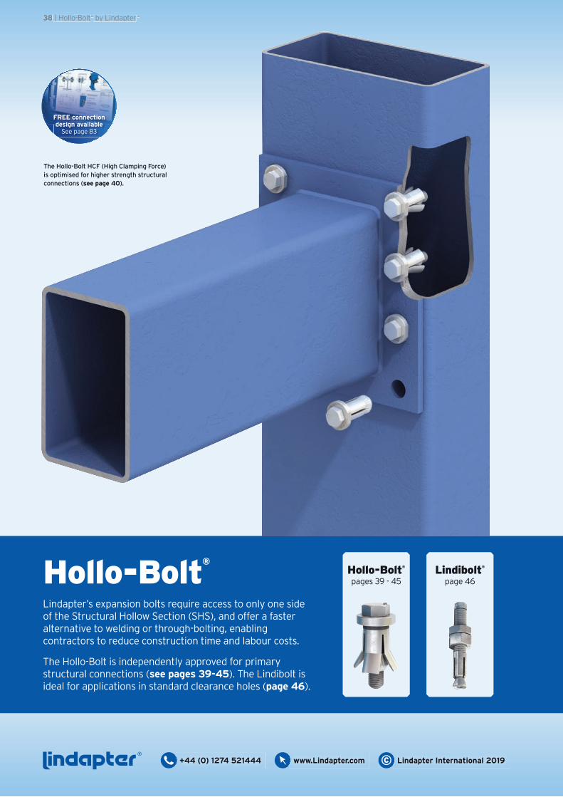
Lindapter’s expansion bolts require access to only one side of the Structural Hollow Section (SHS), and offer a faster alternative to welding or through-bolting, enabling contractors to reduce construction time and labour costs.
The Hollo-Bolt is independently approved for primary structural connections (see pages 39-45). The Lindibolt is ideal for applications in standard clearance holes (page 46).
Hollo-Bolt®
Lindibolt®
page 46Hollo-Bolt®
pages 39 - 45
The Hollo-Bolt HCF (High Clamping Force) is optimised for higher strength structural connections (see page 40).
38 | Hollo-Bolt® by Lindapter®
FREE connection design available
See page 83
®+44 (0) 1274 521444 © Lindapter International 2019www.Lindapter.com
• Fast, cost saving installation from one side.
• For square, rectangular and circular hollow sections.
• High resistance to shear and tension.
• Unique High Clamping Force design.
• A range of head types for architectural finishes.
• CE Mark, TÜV and ICC-ES Seismic approvals.
Hollo-Bolt® by Lindapter®
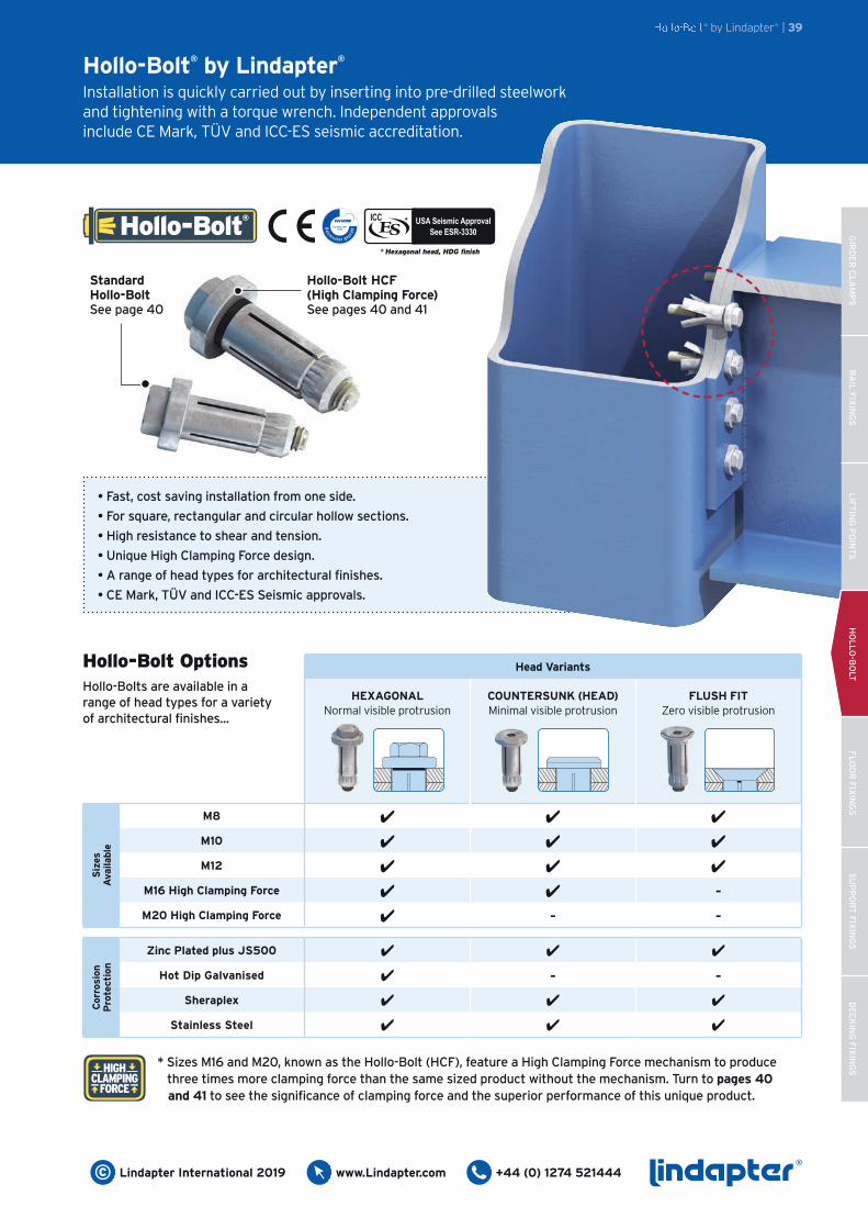
Installation is quickly carried out by inserting into pre-drilled steelwork and tightening with a torque wrench. Independent approvals include CE Mark, TÜV and ICC-ES seismic accreditation.
HIGH CLAMPING
FORCE
* Sizes M16 and M20, known as the Hollo-Bolt (HCF), feature a High Clamping Force mechanism to produce three times more clamping force than the same sized product without the mechanism. Turn to pages 40 and 41 to see the significance of clamping force and the superior performance of this unique product.
Hollo-Bolt HCF (High Clamping Force) See pages 40 and 41
Standard Hollo-Bolt See page 40
Hollo-Bolt® by Lindapter® | 39
Hollo-Bolt®
Head Variants
HEXAGONALNormal visible protrusion
COUNTERSUNK (HEAD)Minimal visible protrusion
FLUSH FITZero visible protrusion
M8 4 4 4
M10 4 4 4
M12 4 4 4
M16 High Clamping Force 4 4 -M20 High Clamping Force 4 - -
Zinc Plated plus JS500 4 4 4
Hot Dip Galvanised 4 - -Sheraplex 4 4 4
Stainless Steel 4 4 4
Siz
es
Ava
ilabl
eC
orro
sion
P
rote
ctio
n
Hollo-Bolt OptionsHollo-Bolts are available in a range of head types for a variety of architectural finishes...
GIR
DE
R C
LA
MP
SR
AIL
FIX
ING
SL
IFT
ING
PO
INT
SH
OL
LO
-BO
LTF
LO
OR
FIX
ING
SS
UP
PO
RT
FIX
ING
SD
EC
KIN
G F
IXIN
GS
* Hexagonal head, HDG finish
USA Seismic Approval See ESR-3330
®+44 (0) 1274 521444www.Lindapter.com© Lindapter International 2019
RA
IL F
IXIN
GS
HO
LL
O-B
OLT
FL
OO
R F
IXIN
GS
SU
PP
OR
T F
IXIN
GS
DE
CK
ING
FIX
ING
SG
IRD
ER
CL
AM
PS
LIF
TIN
G P
OIN
TS
®+44 (0) 1274 521444 © Lindapter International 2019www.Lindapter.com
Hollo-Bolt High Clamping ForceLindapter Hollo-Bolts are available in two versions; the original standard design for general hollow section connections and larger sized High Clamping Force (HCF) for higher strength structural connections.
Siz
es M
8, M
10 a
nd M
12
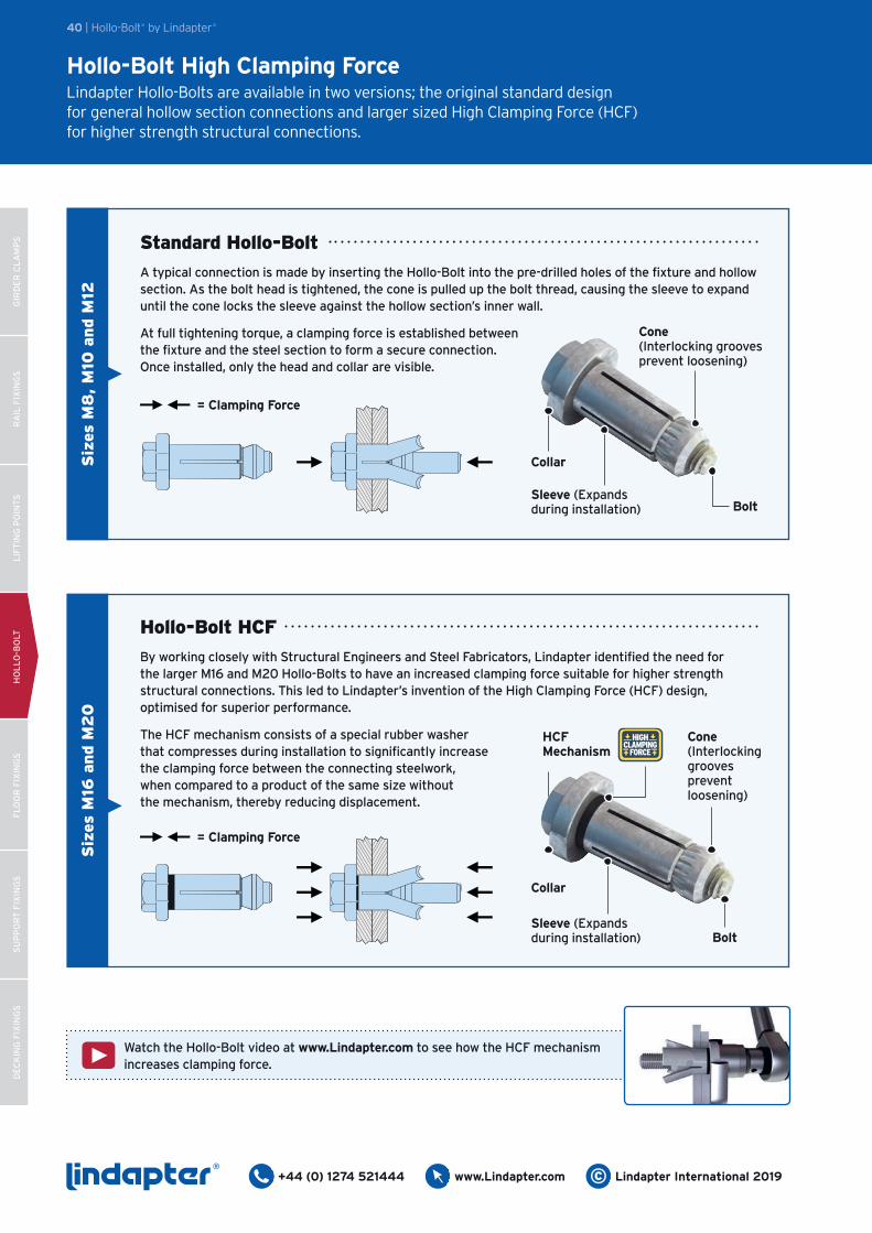
Standard Hollo-Bolt
A typical connection is made by inserting the Hollo-Bolt into the pre-drilled holes of the fixture and hollow section. As the bolt head is tightened, the cone is pulled up the bolt thread, causing the sleeve to expand until the cone locks the sleeve against the hollow section’s inner wall.
At full tightening torque, a clamping force is established between the fixture and the steel section to form a secure connection. Once installed, only the head and collar are visible.
Collar
Cone (Interlocking grooves prevent loosening)
Sleeve (Expands during installation) Bolt
= Clamping Force
Siz
es M
16 a
nd M
20
Hollo-Bolt HCF
By working closely with Structural Engineers and Steel Fabricators, Lindapter identified the need for the larger M16 and M20 Hollo-Bolts to have an increased clamping force suitable for higher strength structural connections. This led to Lindapter’s invention of the High Clamping Force (HCF) design, optimised for superior performance.
The HCF mechanism consists of a special rubber washer that compresses during installation to significantly increase the clamping force between the connecting steelwork, when compared to a product of the same size without the mechanism, thereby reducing displacement.
Collar
Cone (Interlocking grooves prevent loosening)
Sleeve (Expands during installation) Bolt
HCF Mechanism
HIGH CLAMPING
FORCE
= Clamping Force
40 | Hollo-Bolt® by Lindapter®
Watch the Hollo-Bolt video at www.Lindapter.com to see how the HCF mechanism increases clamping force.
GIR
DE
R C
LA
MP
SR
AIL
FIX
ING
SL
IFT
ING
PO
INT
SH
OL
LO
-BO
LTF
LO
OR
FIX
ING
SS
UP
PO
RT
FIX
ING
SD
EC
KIN
G F
IXIN
GS
®+44 (0) 1274 521444www.Lindapter.com© Lindapter International 2019
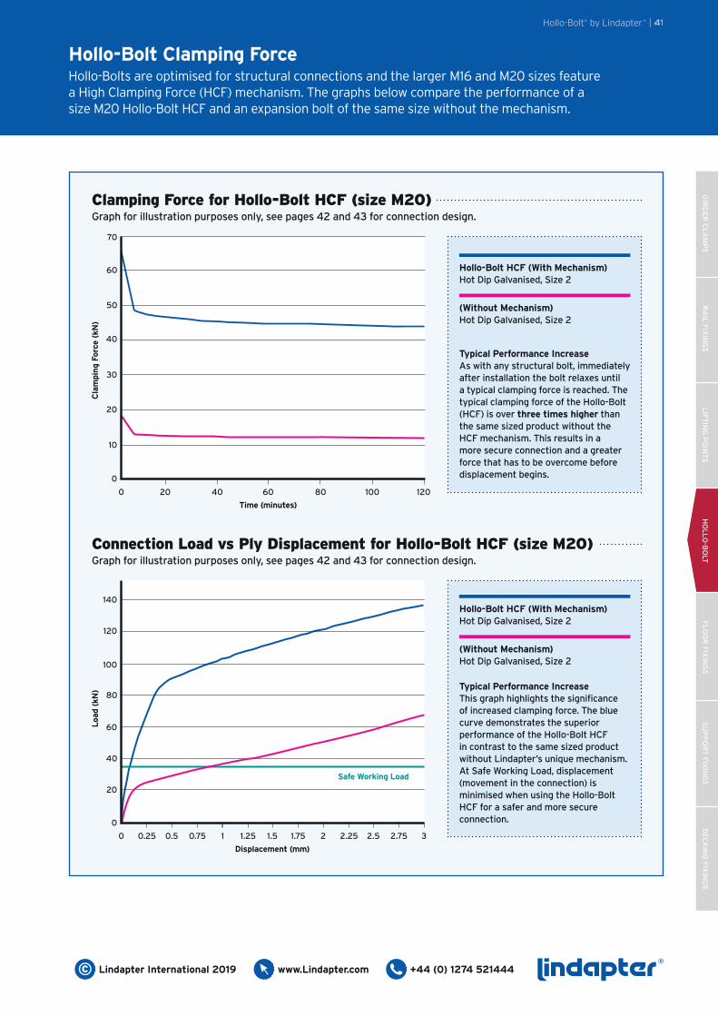
Connection Load vs Ply Displacement for Hollo-Bolt HCF (size M20)Graph for illustration purposes only, see pages 42 and 43 for connection design.
Hollo-Bolt Clamping ForceHollo-Bolts are optimised for structural connections and the larger M16 and M20 sizes feature a High Clamping Force (HCF) mechanism. The graphs below compare the performance of a size M20 Hollo-Bolt HCF and an expansion bolt of the same size without the mechanism.
Clamping Force for Hollo-Bolt HCF (size M20)Graph for illustration purposes only, see pages 42 and 43 for connection design.
0
0
10
20
30
40
50
60
70
Cla
mpi
ng
Forc
e (k
N)
20 40 60 80 100 120
Time (minutes)
Hollo-Bolt® by Lindapter® | 41
Hollo-Bolt HCF (With Mechanism)Hot Dip Galvanised, Size 2
Typical Performance IncreaseAs with any structural bolt, immediately after installation the bolt relaxes until a typical clamping force is reached. The typical clamping force of the Hollo-Bolt (HCF) is over three times higher than the same sized product without the HCF mechanism. This results in a more secure connection and a greater force that has to be overcome before displacement begins.
(Without Mechanism)Hot Dip Galvanised, Size 2
0
20
40
60Loa
d (k
N)
0 0.25
Displacement (mm)
0.5 0.75 1 1.25 1.5 1.75 2 2.25 2.5 2.75 3
80
100
120
140
Safe Working Load
Hollo-Bolt HCF (With Mechanism)Hot Dip Galvanised, Size 2
Typical Performance IncreaseThis graph highlights the significance of increased clamping force. The blue curve demonstrates the superior performance of the Hollo-Bolt HCF in contrast to the same sized product without Lindapter’s unique mechanism. At Safe Working Load, displacement (movement in the connection) is minimised when using the Hollo-Bolt HCF for a safer and more secure connection.
(Without Mechanism)Hot Dip Galvanised, Size 2
RA
IL F
IXIN
GS
HO
LL
O-B
OLT
FL
OO
R F
IXIN
GS
SU
PP
OR
T F
IXIN
GS
DE
CK
ING
FIX
ING
SG
IRD
ER
CL
AM
PS
LIF
TIN
G P
OIN
TS
®+44 (0) 1274 521444 © Lindapter International 2019www.Lindapter.com
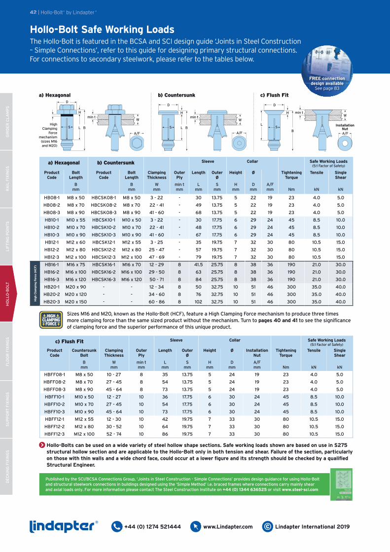
Hollo-Bolt Safe Working LoadsThe Hollo-Bolt is featured in the BCSA and SCI design guide ‘Joints in Steel Construction – Simple Connections’, refer to this guide for designing primary structural connections. For connections to secondary steelwork, please refer to the tables below.
c) Flush Fit Sleeve Collar Safe Working Loads(5:1 Factor of Safety)
Product Code
CountersunkBolt
Clamping Thickness
Outer Ply
Length Outer Ø
Height Ø Installation Nut
Tightening Torque
Tensile Single Shear
Bmm
Wmm
min tmm
Lmm
Smm
Hmm
Dmm
A/Fmm Nm kN kN
HBFF08-1 M8 x 50 10 - 27 8 35 13.75 5 24 19 23 4.0 5.0
HBFF08-2 M8 x 70 27 - 45 8 54 13.75 5 24 19 23 4.0 5.0
HBFF08-3 M8 x 90 45 - 64 8 73 13.75 5 24 19 23 4.0 5.0
HBFF10-1 M10 x 50 12 - 27 10 36 17.75 6 30 24 45 8.5 10.0
HBFF10-2 M10 x 70 27 - 45 10 54 17.75 6 30 24 45 8.5 10.0
HBFF10-3 M10 x 90 45 - 64 10 73 17.75 6 30 24 45 8.5 10.0
HBFF12-1 M12 x 55 12 - 30 10 42 19.75 7 33 30 80 10.5 15.0
HBFF12-2 M12 x 80 30 - 52 10 64 19.75 7 33 30 80 10.5 15.0
HBFF12-3 M12 x 100 52 - 74 10 86 19.75 7 33 30 80 10.5 15.0
HIGH CLAMPING
FORCE
Published by the SCI/BCSA Connections Group, ‘Joints in Steel Construction - Simple Connections’ provides design guidance for using Hollo-Bolt and structural steelwork connections in buildings designed using the ‘Simple Method’ i.e. braced frames where connections carry mainly shear and axial loads only. For more information please contact The Steel Construction Institute on +44 (0) 1344 636525 or visit www.steel-sci.com
a) Hexagonal b) Countersunk Sleeve Collar Safe Working Loads(5:1 Factor of Safety)
Product Code
Bolt Length
Product Code
Bolt Length
Clamping Thickness
Outer Ply
Length Outer Ø
Height Ø Tightening Torque
Tensile Single Shear
Bmm
Bmm
Wmm
min tmm
Lmm
Smm
Hmm
Dmm
A/Fmm Nm kN kN
HB08-1 M8 x 50 HBCSK08-1 M8 x 50 3 - 22 - 30 13.75 5 22 19 23 4.0 5.0
HB08-2 M8 x 70 HBCSK08-2 M8 x 70 22 - 41 - 49 13.75 5 22 19 23 4.0 5.0
HB08-3 M8 x 90 HBCSK08-3 M8 x 90 41 - 60 - 68 13.75 5 22 19 23 4.0 5.0
HB10-1 M10 x 55 HBCSK10-1 M10 x 50 3 - 22 - 30 17.75 6 29 24 45 8.5 10.0
HB10-2 M10 x 70 HBCSK10-2 M10 x 70 22 - 41 - 48 17.75 6 29 24 45 8.5 10.0
HB10-3 M10 x 90 HBCSK10-3 M10 x 90 41 - 60 - 67 17.75 6 29 24 45 8.5 10.0
HB12-1 M12 x 60 HBCSK12-1 M12 x 55 3 - 25 - 35 19.75 7 32 30 80 10.5 15.0
HB12-2 M12 x 80 HBCSK12-2 M12 x 80 25 - 47 - 57 19.75 7 32 30 80 10.5 15.0
HB12-3 M12 x 100 HBCSK12-3 M12 x 100 47 - 69 - 79 19.75 7 32 30 80 10.5 15.0
HB16-1 M16 x 75 HBCSK16-1 M16 x 70 12 - 29 8 41.5 25.75 8 38 36 190 21.0 30.0
HB16-2 M16 x 100 HBCSK16-2 M16 x 100 29 - 50 8 63 25.75 8 38 36 190 21.0 30.0
HB16-3 M16 x 120 HBCSK16-3 M16 x 120 50 - 71 8 84 25.75 8 38 36 190 21.0 30.0
HB20-1 M20 x 90 - - 12 - 34 8 50 32.75 10 51 46 300 35.0 40.0
HB20-2 M20 x 120 - - 34 - 60 8 76 32.75 10 51 46 300 35.0 40.0
HB20-3 M20 x 150 - - 60 - 86 8 102 32.75 10 51 46 300 35.0 40.0Hig
h C
lam
ping
Forc
e (H
CF
)
Sizes M16 and M20, known as the Hollo-Bolt (HCF), feature a High Clamping Force mechanism to produce three times more clamping force than the same sized product without the mechanism. Turn to pages 40 and 41 to see the significance of clamping force and the superior performance of this unique product.
42 | Hollo-Bolt® by Lindapter®
a) Hexagonal
Wmin t
D
H
S L BHigh
Clamping Force
mechanism (sizes M16 and M20)
A/F
b) Countersunk
Wmin t
D
H
S L B
A/F
Hollo-Bolts can be used on a wide variety of steel hollow shape sections. Safe working loads shown are based on use in S275 structural hollow section and are applicable to the Hollo-Bolt only in both tension and shear. Failure of the section, particularly on those with thin walls and a wide chord face, could occur at a lower figure and its strength should be checked by a qualified Structural Engineer.
FREE connection design available
See page 83
c) Flush Fit
Wmin t
D
H
SL
BA/F
Installation Nut
GIR
DE
R C
LA
MP
SR
AIL
FIX
ING
SL
IFT
ING
PO
INT
SH
OL
LO
-BO
LTF
LO
OR
FIX
ING
SS
UP
PO
RT
FIX
ING
SD
EC
KIN
G F
IXIN
GS
®+44 (0) 1274 521444www.Lindapter.com© Lindapter International 2019
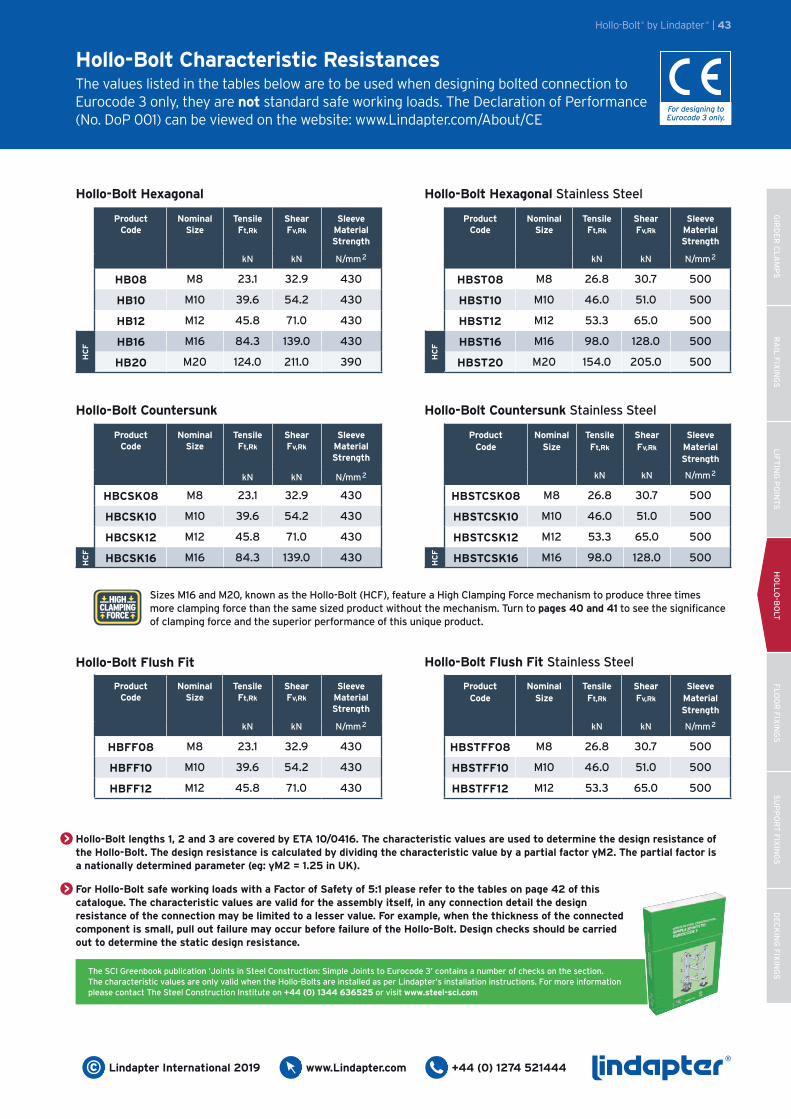
Hollo-Bolt Characteristic ResistancesThe values listed in the tables below are to be used when designing bolted connection to Eurocode 3 only, they are not standard safe working loads. The Declaration of Performance (No. DoP 001) can be viewed on the website: www.Lindapter.com/About/CE
Hollo-Bolt Hexagonal
ProductCode
Nominal Size
TensileFt,Rk
ShearFv,Rk
Sleeve Material Strength
kN kN N/mm2
HB08 M8 23.1 32.9 430
HB10 M10 39.6 54.2 430
HB12 M12 45.8 71.0 430
HB16 M16 84.3 139.0 430
HB20 M20 124.0 211.0 390HC
F
Hollo-Bolt® by Lindapter® | 43
The SCI Greenbook publication ‘Joints in Steel Construction: Simple Joints to Eurocode 3’ contains a number of checks on the section. The characteristic values are only valid when the Hollo-Bolts are installed as per Lindapter’s installation instructions. For more information please contact The Steel Construction Institute on +44 (0) 1344 636525 or visit www.steel-sci.com
Hollo-Bolt Flush Fit Stainless Steel
ProductCode
Nominal Size
TensileFt,Rk
ShearFv,Rk
Sleeve Material Strength
kN kN N/mm2
HBSTFF08 M8 26.8 30.7 500
HBSTFF10 M10 46.0 51.0 500
HBSTFF12 M12 53.3 65.0 500
Hollo-Bolt Hexagonal Stainless Steel
Hollo-Bolt Countersunk Hollo-Bolt Countersunk Stainless Steel
Hollo-Bolt Flush Fit
ProductCode
Nominal Size
TensileFt,Rk
ShearFv,Rk
Sleeve Material Strength
kN kN N/mm2
HBFF08 M8 23.1 32.9 430
HBFF10 M10 39.6 54.2 430
HBFF12 M12 45.8 71.0 430
For designing to Eurocode 3 only.
ProductCode
Nominal Size
TensileFt,Rk
ShearFv,Rk
Sleeve Material Strength
kN kN N/mm2
HBST08 M8 26.8 30.7 500
HBST10 M10 46.0 51.0 500
HBST12 M12 53.3 65.0 500
HBST16 M16 98.0 128.0 500
HBST20 M20 154.0 205.0 500HC
FProduct
CodeNominal
SizeTensileFt,Rk
ShearFv,Rk
Sleeve Material Strength
kN kN N/mm2
HBCSK08 M8 23.1 32.9 430
HBCSK10 M10 39.6 54.2 430
HBCSK12 M12 45.8 71.0 430
HBCSK16 M16 84.3 139.0 430
HC
F
ProductCode
Nominal Size
TensileFt,Rk
ShearFv,Rk
Sleeve Material Strength
kN kN N/mm2
HBSTCSK08 M8 26.8 30.7 500
HBSTCSK10 M10 46.0 51.0 500
HBSTCSK12 M12 53.3 65.0 500
HBSTCSK16 M16 98.0 128.0 500
HC
F
HIGH CLAMPING
FORCE
Sizes M16 and M20, known as the Hollo-Bolt (HCF), feature a High Clamping Force mechanism to produce three times more clamping force than the same sized product without the mechanism. Turn to pages 40 and 41 to see the significance of clamping force and the superior performance of this unique product.
Hollo-Bolt lengths 1, 2 and 3 are covered by ETA 10/0416. The characteristic values are used to determine the design resistance of the Hollo-Bolt. The design resistance is calculated by dividing the characteristic value by a partial factor γM2. The partial factor is a nationally determined parameter (eg: γM2 = 1.25 in UK).
For Hollo-Bolt safe working loads with a Factor of Safety of 5:1 please refer to the tables on page 42 of this catalogue. The characteristic values are valid for the assembly itself, in any connection detail the design resistance of the connection may be limited to a lesser value. For example, when the thickness of the connected component is small, pull out failure may occur before failure of the Hollo-Bolt. Design checks should be carried out to determine the static design resistance.
RA
IL F
IXIN
GS
HO
LL
O-B
OLT
FL
OO
R F
IXIN
GS
SU
PP
OR
T F
IXIN
GS
DE
CK
ING
FIX
ING
SG
IRD
ER
CL
AM
PS
LIF
TIN
G P
OIN
TS
®+44 (0) 1274 521444 © Lindapter International 2019www.Lindapter.com
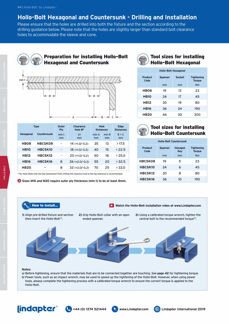
1) Align pre-drilled fixture and section then insert the Hollo-Bolta).
How to install... Watch the Hollo-Bolt installation video at www.Lindapter.com
Notes:a) Before tightening, ensure that the materials that are to be connected together are touching. See page 42 for tightening torque.b) Power tools, such as an impact wrench, may be used to speed up the tightening of the Hollo-Bolt. However, when using power tools, always complete the tightening process with a calibrated torque wrench to ensure the correct torque is applied to the Hollo-Bolt.
2) Grip Hollo-Bolt collar with an open ended spanner.
3) Using a calibrated torque wrench, tighten the central bolt to the recommended torqueb).
Hollo-Bolt Hexagonal and Countersunk - Drilling and InstallationPlease ensure that the holes are drilled into both the fixture and the section according to the drilling guidance below. Please note that the holes are slightly larger than standard bolt clearance holes to accommodate the sleeve and cone.
Sizes M16 and M20 require outer ply thickness (min t) to be at least 8mm.
Type Outer Ply
Clearance Hole Ø*
Hole Distances
Edge Distances
Hexagonal Countersunk min tmm
d1mm
min Amm
min Bmm
B + Cmm
HB08 HBCSK08 - 14 (+1.0/-0.2) 35 13 > 17.5
HB10 HBCSK10 - 18 (+1.0/-0.2) 40 15 > 22.5
HB12 HBCSK12 - 20 (+1.0/-0.2) 50 18 > 25.0
HB16 HBCSK16 8 26 (+2.0/-0.2) 55 20 > 32.5
HB20 - 8 33 (+2.0/-0.2) 70 25 > 33.0
A B C
d1
min t
d1
44 | Hollo-Bolt® by Lindapter®
* For Hollo-Bolts with Hot Dip Galvanised Finish, drilling the clearance hole to the top tolerance is recommended.
Hollo-Bolt Hexagonal
Product Code
Spanner Socket Tightening Torque
mm mm Nm
HB08 19 13 23
HB10 24 17 45
HB12 30 19 80
HB16 36 24 190
HB20 46 30 300
Tool sizes for installingHollo-Bolt Hexagonal
Hollo-Bolt Countersunk
Product Code
Spanner HexagonKey
Tightening Torque
mm mm Nm
HBCSK08 19 5 23
HBCSK10 24 6 45
HBCSK12 30 8 80
HBCSK16 36 10 190
Tool sizes for installingHollo-Bolt Countersunk
Preparation for installing Hollo-Bolt Hexagonal and Countersunk
GIR
DE
R C
LA
MP
SR
AIL
FIX
ING
SL
IFT
ING
PO
INT
SH
OL
LO
-BO
LTF
LO
OR
FIX
ING
SS
UP
PO
RT
FIX
ING
SD
EC
KIN
G F
IXIN
GS
®+44 (0) 1274 521444www.Lindapter.com© Lindapter International 2019
How to install...
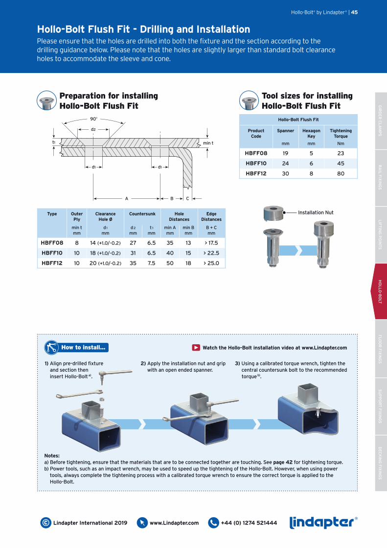
Notes:a) Before tightening, ensure that the materials that are to be connected together are touching. See page 42 for tightening torque.b) Power tools, such as an impact wrench, may be used to speed up the tightening of the Hollo-Bolt. However, when using power tools, always complete the tightening process with a calibrated torque wrench to ensure the correct torque is applied to the Hollo-Bolt.
d1
min t
d2
90O
t1
d1
A B C
Hollo-Bolt Flush Fit - Drilling and InstallationPlease ensure that the holes are drilled into both the fixture and the section according to the drilling guidance below. Please note that the holes are slightly larger than standard bolt clearance holes to accommodate the sleeve and cone.
Hollo-Bolt® by Lindapter® | 45
1) Align pre-drilled fixture and section then insert Hollo-Bolta).
2) Apply the installation nut and grip with an open ended spanner.
3) Using a calibrated torque wrench, tighten the central countersunk bolt to the recommended torqueb).
Installation Nut
Watch the Hollo-Bolt installation video at www.Lindapter.com
Preparation for installing Hollo-Bolt Flush Fit
Hollo-Bolt Flush Fit
Product Code
Spanner HexagonKey
Tightening Torque
mm mm Nm
HBFF08 19 5 23
HBFF10 24 6 45
HBFF12 30 8 80
Type Outer Ply
Clearance Hole Ø
Countersunk Hole Distances
Edge Distances
min tmm
d1
mmd2
mmt1
mmmin Amm
min Bmm
B + Cmm
HBFF08 8 14 (+1.0/-0.2) 27 6.5 35 13 > 17.5
HBFF10 10 18 (+1.0/-0.2) 31 6.5 40 15 > 22.5
HBFF12 10 20 (+1.0/-0.2) 35 7.5 50 18 > 25.0
Tool sizes for installingHollo-Bolt Flush Fit
RA
IL F
IXIN
GS
HO
LL
O-B
OLT
FL
OO
R F
IXIN
GS
SU
PP
OR
T F
IXIN
GS
DE
CK
ING
FIX
ING
SG
IRD
ER
CL
AM
PS
LIF
TIN
G P
OIN
TS
®+44 (0) 1274 521444 © Lindapter International 2019www.Lindapter.com
46 | Hollo-Bolt® by Lindapter®
Washer
Setscrew
Locknut Nut Main Body
Cone
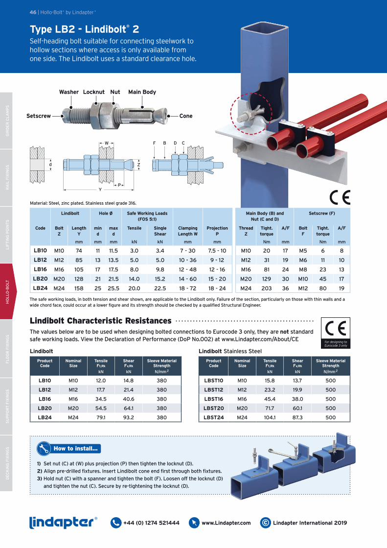
Type LB2 - Lindibolt® 2Self-heading bolt suitable for connecting steelwork to hollow sections where access is only available from one side. The Lindibolt uses a standard clearance hole.
1) Set nut (C) at (W) plus projection (P) then tighten the locknut (D).
2) Align pre-drilled fixtures. Insert Lindibolt cone end first through both fixtures.
3) Hold nut (C) with a spanner and tighten the bolt (F). Loosen off the locknut (D)
and tighten the nut (C). Secure by re-tightening the locknut (D).
How to install...
ProductCode
Nominal Size
TensileFt,Rk
ShearFv,Rk
Sleeve Material Strength
kN kN N/mm2
LB10 M10 12.0 14.8 380
LB12 M12 17.7 21.4 380
LB16 M16 34.5 40.6 380
LB20 M20 54.5 64.1 380
LB24 M24 79.1 93.2 380
Lindibolt
Lindibolt Characteristic ResistancesThe values below are to be used when designing bolted connections to Eurocode 3 only, they are not standard safe working loads. View the Declaration of Performance (DoP No.002) at www.Lindapter.com/About/CE
Lindibolt Hole Ø Safe Working Loads(FOS 5:1)
Main Body (B) and Nut (C and D)
Setscrew (F)
Code Bolt Z
Length Y
min d
max d
Tensile Single Shear
Clamping Length W
Projection P
Thread Z
Tight. torque
A/F Bolt F
Tight. torque
A/F
mm mm mm kN kN mm mm Nm mm Nm mm
LB10 M10 74 11 11.5 3.0 3.4 7 - 30 7.5 - 10 M10 20 17 M5 6 8
LB12 M12 85 13 13.5 5.0 5.0 10 - 36 9 - 12 M12 31 19 M6 11 10
LB16 M16 105 17 17.5 8.0 9.8 12 - 48 12 - 16 M16 81 24 M8 23 13
LB20 M20 128 21 21.5 14.0 15.2 14 - 60 15 - 20 M20 129 30 M10 45 17
LB24 M24 158 25 25.5 20.0 22.5 18 - 72 18 - 24 M24 203 36 M12 80 19
ProductCode
Nominal Size
TensileFt,Rk
ShearFv,Rk
Sleeve Material Strength
kN kN N/mm2
LBST10 M10 15.8 13.7 500
LBST12 M12 23.2 19.9 500
LBST16 M16 45.4 38.0 500
LBST20 M20 71.7 60.1 500
LBST24 M24 104.1 87.3 500
The safe working loads, in both tension and shear shown, are applicable to the Lindibolt only. Failure of the section, particularly on those with thin walls and a wide chord face, could occur at a lower figure and its strength should be checked by a qualified Structural Engineer.
Lindibolt Stainless Steel
Material: Steel, zinc plated. Stainless steel grade 316.
Y
d
P
W
Z
F D CB
For designing to Eurocode 3 only
GIR
DE
R C
LA
MP
SR
AIL
FIX
ING
SL
IFT
ING
PO
INT
SH
OL
LO
-BO
LTF
LO
OR
FIX
ING
SS
UP
PO
RT
FIX
ING
SD
EC
KIN
G F
IXIN
GS
®+44 (0) 1274 521444www.Lindapter.com© Lindapter International 2019
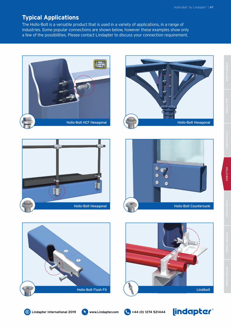
Typical ApplicationsThe Hollo-Bolt is a versatile product that is used in a variety of applications, in a range of industries. Some popular connections are shown below, however these examples show only a few of the possibilities. Please contact Lindapter to discuss your connection requirement.
Hollo-Bolt® by Lindapter® | 47
Hollo-Bolt HCF Hexagonal
HIGH CLAMPING
FORCE
Hollo-Bolt Hexagonal
Hollo-Bolt Hexagonal
Hollo-Bolt Countersunk
Hollo-Bolt Flush Fit Lindibolt