Monitor and Optimize PID Loop Performance With Aspen PID Watch
92 IEEE TRANSACTIONS ON INDUSTRIAL INFORMATICS, VOL. 10, NO. 1, FEBRUARY 2014
Holistic Indices for Productivity Control Assessment,Applied to the Comparative Analysis of PID andFuzzy Controllers Within an Isasmelt Furnace
Juan Manuel Ojeda, Josep M. Fuertes, Senior Member, IEEE, and Eulàlia Griful
Abstract—This research aims to contribute to the analysis ofcontrol performance assessment in extractive metallurgy. Produc-tivity-based indices are proposed in addition to current measuringtechniques. Such criteria are employed to compare conventionalPID and fuzzy-based controllers in copper smelting. This processis mathematically modeled in order to be simulated. The com-parison confirms a better performance of the fuzzy controllerin dealing with the molten bath temperature within an Isasmeltfurnace. In normal operating conditions (online tests), the pro-posed controller achieves a consistent mean square relative errorreduction of 72% between measured values and the temperaturesetpoint and standard deviation of approximately 60% (from27.8 C to 11.1 C). The productivity criteria establish a lowerconsumption of raw materials (13%) and energy supply (29%).
Index Terms—Control assessment, copper smelting, Isasmeltfurnace, performance index, productivity.
I. INTRODUCTION
C ONTROLLER performance assessment and monitoringapplications are critical in industrial processes [1]. In the
past decades, there has been a considerable effort in developingadequate indices for these tasks [2], [3]. Current methods aremainly focused on controller behavior, cover performance char-acteristics constraints, or user-specified benchmarks [4], [5], butnot necessarily with regard to the production system [6], [7].This work introduces productivity criteria to measure the im-
pact of control designs in metallurgical processes. The approachhas been applied in a Peru-based copper smelter to compare con-ventional and fuzzy controllers. Both control designs have dealtwith the molten bath temperature within an Isasmelt furnace [8].It has become possible to make this comparison by mathe-
matically modeling the copper smelting process [9]. This modelincludes thermodynamic aspects of oxidation and reduction re-actions as well as themass and energy balance inside the furnace[10], [11]. The model has been validated by comparing simu-lated output variables (bath temperature and tip pressure) to thereal data.
Manuscript received November 28, 2011; revised March 14, 2012, October28, 2012; accepted July 08, 2013. Date of publication August 06, 2013; dateof current version December 12, 2014. This work was supported in part by theSpanish EVENTS project CICYT DPI2010-18601 and by the Spanish Agencyfor International Development Cooperation. Paper no. TII-11-817.J. M. Ojeda and J. M. Fuertes are with the Department of Automatic Con-
trol, Technical University of Catalonia, 08028 Barcelona, Spain (e-mail: [email protected]; [email protected]).E. Griful is with the Department of Statistics, Technical University of Cat-
alonia, 08028 Barcelona, Spain (e-mail: [email protected]).Color versions of one or more of the figures in this paper are available online
at http://ieeexplore.ieee.org.Digital Object Identifier 10.1109/TII.2013.2276743
This process is carried out at temperatures between 1180 Cand 1190 C. The heat required to sustain the thermodynamicreactions is given by copper sulphur burning; however, some-times coal and eventually supplementary fuel oil are added tomaintain a normal operation. Therefore, oxygen-enriched air iscontinually injected into the molten slag phase to prevent safetyhazards [12].The molten bath temperature should be maintained at the de-
sired value, keeping the associated variables within their ade-quate operation range, but mainly using fewer resources to reachthe same level of service [13]. In testing these controllers, tem-perature error (with respect to the set point) is initially consid-ered as the main index [14]. To determine the impact on theprocess efficiency, this information is complemented by singleproductivity indices, such as tons of smelted concentrate per tonof coal and per liter of oil [15], [16].This paper is organized into six sections. The introduction
is presented in Section I, and the metallurgical process is de-scribed in Section II. Sections III and IV detail current and pro-posed controllers, respectively. Section V presents the resultsfrom using compared controllers on a simulated plant, focusingon performance and productivity indices. Finally, in Section VI,the conclusion is presented.
II. METALLURGICAL PROCESS
In the Isasmelt process, the furnace is fed by a homogeneousmixture of copper concentrate , fluxes such as silica
and coquina, as well as coal and water .In order to simplify the mathematical model, only the additionof silica flux are considered. The reaction yields a matte phase(mixed copper-iron sulphide), a slag phase (iron oxide), and anoffgas phase (mostly sulphur dioxide, nitrogen, watervapor, and carbon dioxide).This process is maintained by adding industrial oxygen
to the blown air , resulting in enriched airwith 60%–70% of oxygen. It is performed through a verticallance submerged in the bath of molten material, where theslag is oxidized to subsequently form the magnetite [17] (seeFig. 1). The reaction mechanism occurs at two independentsites in the slag phase: one for fast oxidation and the other forslow reaction.In the oxidizing reaction, the chalcopyrite (CuFeS ) con-
tained in the concentrate reacts with the liquid oxygen from themagnetite. In the reduction site, the slag is partially reducedwith lump coal to regulate magnetite level. The tapping flow
of molten material is discharged into the RHF furnace insemi-continuous process or batch, allowing mechanical settling
1551-3203 © 2013 IEEE

OJEDA et al.: HOLISTIC INDICES FOR PRODUCTIVITY CONTROL ASSESSMENT 93
Fig. 1. Simplified model of the Isasmelt furnace.
of the matte and the slag while gases from smelting are treatedto be converted in sulfuric acid.
A. Dynamic Mass Balance
The dynamic mass balance of molten material within thefurnace is given by
(1)
This equation is determined by the inflow rate of raw materials(copper concentrate, fluxes, and water) and enriched air, andthe outflow rate of resulting products (tapping flow and gases),neglecting small mass loss due to handling operations
(2)
where
(3)
Then, this equation may be expressed as
(4)
However, after analyzing historical data from the plant, anequivalence relation between the resulting gas mass of thisprocess and the amount mass of silica, water, reverts,coal, and enriched air is found as follows:
(5)
This equivalence of masses also appears in related works [18]and, in this case, specifically allows the equation to be simplifiedto
(6)
B. Dynamic Energy Balance
This dynamic energy balance can be expressed in terms ofsummations of the input–output energy and the rate of heat gen-eration. The subscript is given by
, and ; the subscript is given byif heat is from pyritic decomposition and
if heat is due to oil combustion; is equal to, and correspond to the inlet
and outlet temperatures.In this balance, it is assumed that no heat is lost to
the vessel outside, and the minimal contributions ofand to this process are ignored. The units are
[kg/s] [lt/s], [J/kg- C] [kg] C] and [J/s]:
(7)
Then, deriving the left side of (7) results in
(8)
Substituting (6) into (8) and reordering results in
(9)
The following expression displays the heating componentsof this process, assuming that the rate of heat generation
due to pyritic decomposition and related reactions, de-pends on the oxygen factor and that the rate of oilcombustion is given by its specific energy con-sumption [19]:
(10)
In addition, this equation expands term by term the main reac-tion products.The model becomes simplified in
(11)
by neglecting the heat contribution of SO and H O gases tothis process. This expression also includes the equivalence
, where is the average density of the molten bath, isthe circular section of the furnace, and is the bath height.
94 IEEE TRANSACTIONS ON INDUSTRIAL INFORMATICS, VOL. 10, NO. 1, FEBRUARY 2014
The differential equation can be linearized by the Taylorseries expansion at the steady-state operating point
, . Then, substitutinginto (11), it becomes
(12)
The feeding temperature at initial conditions are approxi-mately constant such that . Therefore,(12) becomes
(13)
where , and are deviation variablesfrom the base point.Furthermore, (13) can be written in terms of small increments
above steady-state conditions [20], [21] as
(14)
where
The parametric vectors are calculated using stored data andapplying finite difference methods (forward difference), wherecorresponds to the value of the function at time and(s) is the sampling period.
(15)
Finally, the coefficients are obtained by applying the leastsquares method as follows:
(16)
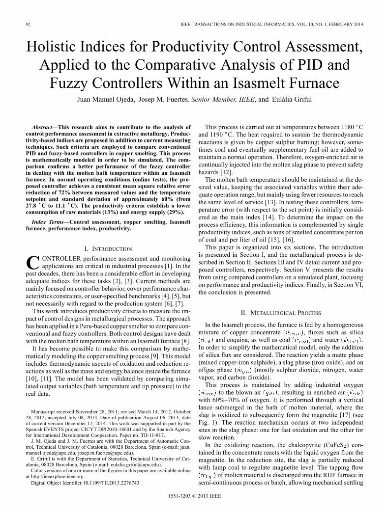
Fig. 2. Control system diagram of the Isasmelt furnace.
III. FURNACE CONTROL SYSTEM
The flow ratios of oxygen and nitrogen injected into thisprocess are given in
(17)
(18)
The control logic uses the concentrate, coal and oil rates as afeed forward index to directly set the total oxygen demand
(19)
The enriched air
(20)
is calculated by dividing the required oxygen for this process bythe percentage of % O enrichment
%(21)
The mathematical model of the plant is obtained by taking theLaplace transform of (14) to yield
(22)
where
(23)
Substituting (18) and (21) into (22) yields
(24)
with
% (25)
A. Current Temperature Control
The furnace temperature is regulated by using a cascadecontrol strategy. A PID controller (TIC354) in primary loop

OJEDA et al.: HOLISTIC INDICES FOR PRODUCTIVITY CONTROL ASSESSMENT 95
TABLE IUNIVERSE OF DISCOURSE
keeps the temperature values of thermocouples, located in thebath region of the furnace (TT354-A, B, C and D), close tothe set point (1180 C). The output is transmitted to the maincontroller (FIC115), which remotely fixes the respective setpoints of summing components, that means oxygen (FIC103),air (FIC113), and oil (FIC123) PID control blocks in secondaryloop [22]–[24] (see Fig. 2). These set points are established bythe concentrate and combustion requirements. The containedsulphur is burnt maintaining the process heat (over 1100 C).If the sulphur content is not sufficient to sustain the level ofheating, coal and eventually extra fuel oil are also added inparallel to achieve the desired temperature.
B. Oxygen Control Subsystem
The oxygen-enriched air is injected into the furnace througha vertical lance, which is submerged in the slag bath. The depthof immersion is set automatically by the lance tip pressure. Thespecific oxygen ratio setting is calculated by multiplying thesingle requirement by its respective flow rate (i.e., oxygen/oilby oil flow).The matte grade (range of 60%–65%) and slag composition
(range of 32%–34%) are dependent upon this calculation [25].An algorithm is incorporated into the main control to periodi-cally make ratio adjustments of O enrichment, which is basedon periodic matte and slag samples (taken approximately oncean hour). However, due to time delays, corrections are nottimely executed [26].
IV. PROPOSED CONTROL SYSTEM
The proposed control system includes a temperature fuzzycontroller instead of using a PID controller in the cascade con-trol scheme. It is complemented with a sampling-based pre-dictor for forecasting the mate and slag composition. This pre-diction allows to timely adjust ratios of oxygen in parallel tosample collection. The inputs for the fuzzy controller are thebath temperature ( C), its rate of change ( C/s) and the feedflow of concentrate (although this variable has been discardedas of late due to the large number of rules and high computa-tional cost). The outputs includes the percentage of O enrich-ment and in a latter phase the flow rate of oil. Features of fuzzyvariables, controller divisions and functions are summarized inTable I, and details of membership functions are presented inTable II.
A. Fuzzy Rules
Fuzzy rules are built in accordance with the operators’ ex-perience in handling the furnace temperature. The performancereached by the operators in the past six months (under differentoperating circumstances) is analyzed. The rules based on thisanalysis are described in the Table III. The flow of concentrate
TABLE IILINGUISTIC TERMS
TABLE IIIFUZZY CONTROL RULES
is initially considered as input, but due to the high computationalcost and the large number of created rules, it is discarded.
B. Metallurgical Predictor Module
The predictor module is designed to estimate the tapping flowcomposition (Cu in matte and SiO in the slag) in order to makefaster calculation and take timely corrective action [27] to ratiosof oxygen enrichment. This module has included as input vari-ables the flow rate of oxygen , coal , concentrate
and oil , as well as the molten bath temperature(T) [28], [29]. This predictor presents the following features.• Feedforward backpropagation network.• Normalization of input data.• First layer with ten neurons and logsig transfer function.• Second layer with 20 neurons and logsig transfer function.• Third layer with one neuron and logsig transfer function.• Training type is trainlm.
C. Control Indices
Indices provide quantitative and reliable references in indus-trial processes. They should be measurable, reachable, relevant,reliable, comparable, and contextually appropriate. In controltheory, indices are used to evaluate the control performanceand help to move design features toward a desired pattern [30].However, the main disadvantage of mostly indexes is the diffi-culty of linking control performance and process efficiency, andtherefore to convert such ratios into economic measures.The differences between the temperature set point and the
reached values from both controllers are calculated by the meansquare relative error
% (26)
and the dispersion of these values by the standard deviation ,where is the temperature process value (measured value),
96 IEEE TRANSACTIONS ON INDUSTRIAL INFORMATICS, VOL. 10, NO. 1, FEBRUARY 2014
is the temperature set point (desired value), and is thenumber of samples.In addition to performance measures, single indices based on
the process productivity are proposed. Those indices are thetime efficiency and the consumption of energetic resources incopper smelting. Time efficiency (TE) is an index of the fur-nace operation availability and is given as
(27)
It is calculated by dividing the cumulative stopover time of fur-nace operations over a six-month period (stopovers are causedby high temperature oscillations due to poor control).The energetic usage is a productivity based index that is de-
fined as the ratio of tons of smelted concentrate to 1 ton of re-quired ressources such as coal
(28)
and fuel oil
(29)
These indices are helpful to evaluate the impact of the controlperformance on the process efficiency. A typical issue occurswhen the control fails to maintain the process heat above 1100C, coal and eventually oil undergo a rapid increase in tempera-ture due to their intensive energy release. In the above equations,represents tonnes, represents hours, and represents liters.
V. RESULTS
A. Furnace Simulation
Furnace operation with the current controller is simulatedunder normal process plant conditions. The input variables usedin this model are the feed flow of concentrate and coal (kg/s),and the oxygen-enrichment percentage % , as well as theoperation set points of the process. The output variables includethe bath temperature C) and the tip pressure (KPa). The fol-lowing assumptions are considered in the simulation of the fur-nace operation.• Furnace temperature is at 1180 C.• The initial bath level is 1 m high to simulate the tip pressurecontroller.
• There is a continuous stable flow of air, oxygen, and oil.This model has been validated using historical (stored) data
from an Isasmelt copper smelter in Peru (observing 8-h periodsrun from December 15th to 30th, 2007). One hundred twentyobservations of 10 min each were recorded. The sample size iscalculated using
(30)
where represents a confidence interval of 95%, is thecurrent population standard deviation, and is the error of es-timation. Validation has been possible by comparing simulatedand measured real outputs (bath temperature and tip pressure).
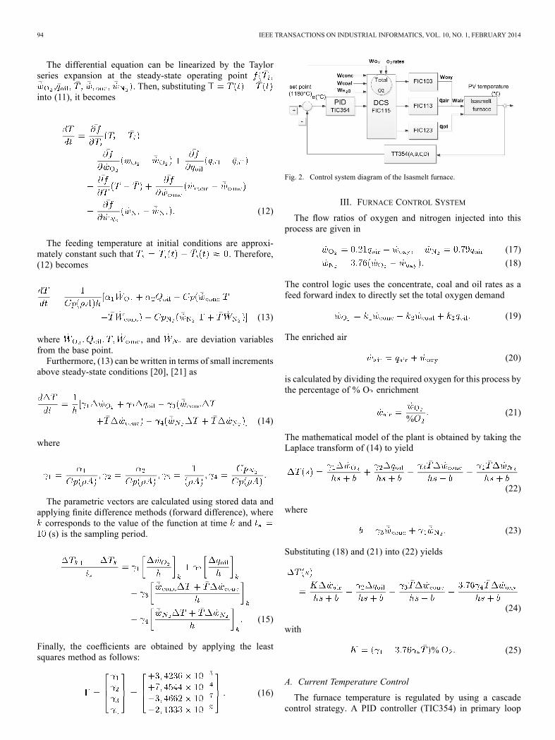
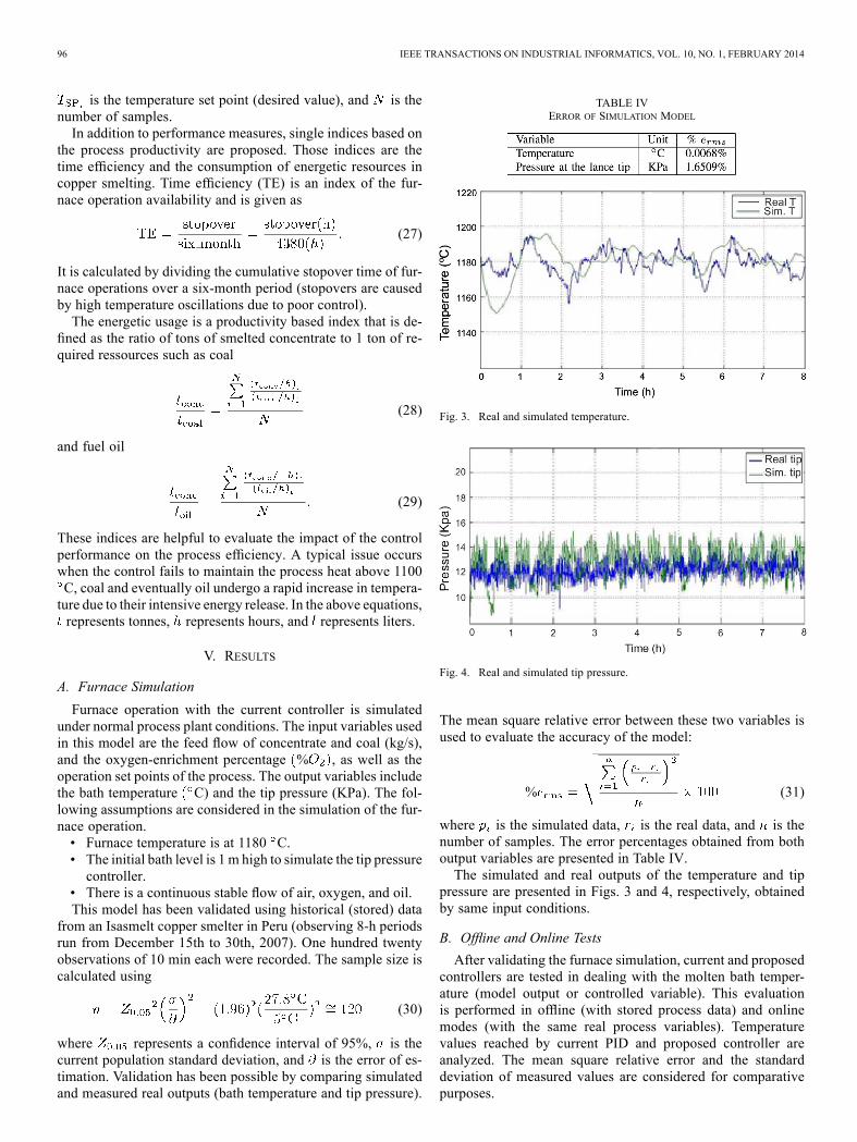
TABLE IVERROR OF SIMULATION MODEL
Fig. 3. Real and simulated temperature.
Fig. 4. Real and simulated tip pressure.
The mean square relative error between these two variables isused to evaluate the accuracy of the model:
% (31)
where is the simulated data, is the real data, and is thenumber of samples. The error percentages obtained from bothoutput variables are presented in Table IV.The simulated and real outputs of the temperature and tip
pressure are presented in Figs. 3 and 4, respectively, obtainedby same input conditions.
B. Offline and Online Tests
After validating the furnace simulation, current and proposedcontrollers are tested in dealing with the molten bath temper-ature (model output or controlled variable). This evaluationis performed in offline (with stored process data) and onlinemodes (with the same real process variables). Temperaturevalues reached by current PID and proposed controller areanalyzed. The mean square relative error and the standarddeviation of measured values are considered for comparativepurposes.
OJEDA et al.: HOLISTIC INDICES FOR PRODUCTIVITY CONTROL ASSESSMENT 97
TABLE VOFFLINE COMPARISON OF CONTROLLERS
TABLE VIONLINE COMPARISON OF CONTROLLERS
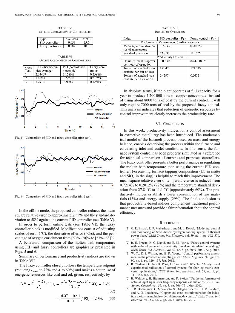
Fig. 5. Comparison of PID and fuzzy controller (first test).
Fig. 6. Comparison of PID and fuzzy controller (third test).
In the offline mode, the proposed controller reduces the meansquare relative error to approximately 55% and the standard de-viation to 58% against the current PID controller (see Table V).In order to perform online tests (see Table VI), the fuzzy
controller block is modified. Modifications consist of adjustingscales of error ( C), the derivative of error ( C/s), and the per-centage of oxygen enrichment from [60%–70]% to [57%–68]%.A behavioral comparison of the molten bath temperature
using PID and fuzzy controllers are graphically presented inFigs. 5 and 6.Summary of performance and productivity indices are shown
in Table VII.The fuzzy controller closely follows the temperature setpoint
(reducing to 72% and to 60%) and makes a better use ofenergetic resources like coal and oil, given, respectively, by
%
(32)
% (33)
TABLE VIIINDICES OF OPERATION
In absolute terms, if the plant operates at full capacity for ayear to produce 1 200 000 tons of copper concentrate, insteadof using about 8000 tons of coal by the current control, it willonly require 7000 tons of coal by the proposed fuzzy control.This analysis indicates that reduction of energetic resources bycontrol improvement clearly increases the productivity rate.
VI. CONCLUSION
In this work, productivity indices for a control assessmentin extractive metallurgy has been introduced. The mathemat-ical model of the Isasmelt process, based on mass and energybalance, enables describing the process within the furnace andcalculating inlet and outlet conditions. In this sense, the fur-nace system control has been properly simulated as a referencefor technical comparison of current and proposed controllers.The fuzzy controller presents a better performance in regulatingthe molten bath temperature than using the current PID con-troller. Forecasting furnace tapping composition (Cu in matteand SiO in the slag) is helpful to reach this improvement. Themean square relative error of temperature error is reduced from0.7214% to 0.2012% (72%) and the temperature standard devi-ation from 27.8 C to 11.1 C (approximately 60%). The pro-ductivity indices establish a lower consumption of raw mate-rials (13%) and energy supply (29%). The final conclusion isthat productivity-based indices complement traditional perfor-mancemeasures and provide a fair information about the controlefficiency.
REFERENCES
[1] G. R. Biswal, R. P. Maheshwari, and M. L. Dewal, “Modeling, controland monitoring of S3RS-based hydrogen cooling system in thermalpower plant,” IEEE Trans. Ind. Electron., vol. 59, no. 1, pp. 562–570,Jan. 2012.
[2] R.-E. Precup, R.-C. David, and E. M. Petriu, “Fuzzy control systemswith reduced parametric sensitivity based on simulated annealing,”IEEE Trans. Ind. Electron., vol. 59, no. 8, pp. 3049–3061, Aug. 2012.
[3] W. Yu, D. I. Wilson, and B. R. Young, “Control performance assess-ment in the presence of sampling jitter,” Chem. Eng. Res. Design, vol.90, no. 1, pp. 129–137, Jan. 2012.
[4] R. Cardenas, C. Juri, R. Pena, J. Clare, and P. Wheeler, “Analysis andexperimental validation of control systems for four-leg matrix con-verter applications,” IEEE Trans. Ind. Electron., vol. 59, no. 1, pp.141–153, Jan. 2012.
[5] B. Wahlberg, H. Hjalmarsson, and P. Stoica, “On the performance ofoptimal input signals for frequency response estimation,” IEEE Trans.Autom. Control, vol. 57, no. 3, pp. 766–771, Mar. 2012.
[6] J. R. Dominguez, C. Mora-Soto, S. Ortega-Cisneros, J. J. R. Panduro,and A. G. Loukianov, “Copper and core loss minimization for induc-tion motors using high-order sliding-mode control,” IEEE Trans. Ind.Electron., vol. 59, no. 7, pp. 2877–2889, Jul. 2012.
98 IEEE TRANSACTIONS ON INDUSTRIAL INFORMATICS, VOL. 10, NO. 1, FEBRUARY 2014
[7] R.-E. Precup, R.-C. David, E. M. Petriu, S. Preitl, and M.-B. Radac,“Fuzzy control systems with reduced parametric sensitivity based onsimulated annealing,” IEEE Trans. Ind. Electron., vol. 59, no. 8, pp.3049–3061, Aug. 2012.
[8] G. V. Kaigala, H. J. Marquez, and C. J. Backhouse, “Nonlinear con-troller designs for thermal management in PCR amplification,” IEEETrans. Control Syst. Technol., vol. 20, no. 1, pp. 11–30, Jan. 2012.
[9] G. R. Biswal, R. P. Maheshwari, and M. L. Dewal, “Modeling, control,and monitoring of RS-based hydrogen cooling system in thermalpower plant,” IEEE Trans. Ind. Electron., vol. 59, no. 1, pp. 562–570,Jan. 2012.
[10] M. Nagamori, W. J. Errington, P. Mackey, and D. Poggi, “Thermo-dynamic simulation model of the Isasmelt process for copper matte,”Metallurgical Mater. Trans. B, vol. 25, pp. 839–853, 1994.
[11] C. Gao, L. Jian, and S. Luo, “Modeling of the thermal state change ofblast furnace hearth with support vector machines,” IEEE Trans. Ind.Electron., vol. 59, no. 2, pp. 1134–1145, Feb. 2012.
[12] R. N. Dean, D. K. Harris, A. Y. Palkar, and G. D. Wonacott, “Liquidmetal-filled micro heat pipes for thermal management of solid-statedevices,” IEEE Trans. Ind. Electron., vol. 59, no. 12, pp. 4888–4894,Dec. 2012.
[13] H.-N. Wu and H.-X. Li, “A multiobjective optimization based fuzzycontrol for nonlinear spatially distributed processes with application toa catalytic rod,” IEEE Trans. Ind. Inf., vol. 8, no. 4, pp. 860–868, Nov.2012.
[14] J. Rodriguez, R. M. Kennel, J. R. Espinoza, M. Trincado, C. A. Silva,and C. A. Rojas, “High-performance control strategies for electricaldrives: An experimental assessment,” IEEE Trans. Ind. Electron., vol.59, no. 2, pp. 812–820, Feb. 2012.
[15] E. Ibarra, I. Kortabarria, J. Andreu, I. M. de Alegria, J. L. Martin, and P.Ibañez, “Improvement of the design process of matrix converter plat-forms using the switching state matrix averaging simulation method,”IEEE Trans. Ind. Electron., vol. 59, no. 1, pp. 220–234, Jan. 2012.
[16] T. Samad and G. Stewart, “Perspectives on innovation in control sys-tems technology: Compatibility with industry practices,” IEEE Trans.Control Syst. Technol., vol. 21, no. 2, pp. 284–288, Mar. 2013.
[17] G. Alvear and S. Nikolic, “Isasmelt for recycling of valuable elementscontributing to a more sustainable society,” in REWAS 2013: EnablingMaterials Resource Sustainability. Hoboken, NJ, USA: Wiley, 2013.
[18] G. Alvear, P. Arthur, and P. Partington, “Feasibility to profitability withcopper Isasmelt,” in Copper 2010, Clausthal-Zellerfeld, Germany, vol.2, Pyrometallurgy I, GDMB, pp. 615–630.
[19] P. Yadav, R. Kumar, S. K. Panda, and C. S. Chang, “Energy-efficientthrust allocation for semi-submersible oil rig platforms using improvedharmony search algorithm,” IEEE Trans. Ind. Inf., vol. 8, no. 4, pp.913–924, Nov. 2012.
[20] S. Golestan, M. Monfared, F. D. Freijedo, and J. Guerrero, “Dynamicsassessment of advanced single-phase PLL structures,” IEEE Trans.Ind. Electron., vol. 60, no. 6, pp. 2167–2177, Jun. 2013.
[21] B. Lennartson, R. H. Middleton, and I. Gustafsson, “Numerical sen-sitivity of linear matrix inequalities using shift and delta operators,”IEEE Trans. Autom. Control, vol. 57, no. 11, pp. 2874–2879, Nov.2012.
[22] J. Chavarria, D. Biel, F. Guinjoan, C. Meza, and J. J. Negroni, “En-ergy-balance control of PV cascademultilevel grid-connected invertersunder level-shifted and phase-shifted PWMs,” IEEE Trans. Ind. Elec-tron., vol. 60, no. 1, pp. 98–111, Jan. 2013.
[23] Z. Chen, Y. Luo, and M. Chen, “Control and performance of acascaded shunt active power filter for aircraft electric power system,”IEEE Trans. Ind. Electron., vol. 59, no. 9, pp. 3614–3623, Sep. 2012.
[24] L. Jian and C. Gao, “Binary coding SVMs for the multiclass problemof blast furnace system,” IEEE Trans. Ind. Electron., vol. 60, no. 9, pp.3846–3856, Sep. 2013.
[25] Y. Chen, “Implementation of integrated automatic control systemof copper smelter based on bath smelting technique,” Int. J. Manuf.Technol. Manag., vol. 25, no. 13, pp. 224–236, Aug. 2012.
[26] J. Rodríguez, R. M. Kennel, J. R. Espinoza, M. Trincado, C. A. Silva,and C. A. Rojas, “High-performance control strategies for electricaldrives: An experimental assessment,” IEEE Trans. Ind. Electron., vol.59, no. 2, pp. 812–820, Feb. 2012.
[27] D. Q. Truong, K. K. Ahn, and N. T. Trung, “Design of an advancedtime delay measurement and a smart adaptive unequal interval greypredictor for real-time nonlinear control systems,” IEEE Trans. Ind.Electron., vol. 60, no. 10, pp. 4574–4589, Oct. 2013.
[28] X. Jing and L. Cheng, “An optimal PID control algorithm for trainingfeedforward neural networks,” IEEE Trans. Ind. Electron., vol. 60, no.6, pp. 2273–2283, Jun. 2013.
[29] Y. Pan and J. Wang, “Model predictive control of unknown nonlineardynamical systems based on recurrent neural networks,” IEEE Trans.Ind. Electron., vol. 59, no. 8, pp. 3089–3101, Aug. 2012.
[30] R. Cardenas, C. Juri, R. Pena, J. Clare, and P. Wheeler, “Analysis andexperimental validation of control systems for four-leg matrix con-verter applications,” IEEE Trans. Ind. Electron., vol. 59, no. 1, pp.141–153, Jan. 2012.
Juan Manuel Ojeda received the IndustrialEngineering degree from the University ofLima, Lima, Peru, in 2003, the M.Sc. degreein energy management from the University ofKoblenz-Landau, Koblenz, Germany, in 2009,the M.Sc. degree in systems engineering fromthe National University of Engineering, Peru,in 2010, and the M.Sc. degree in automaticand robotics from the Technical University ofCatalonia, Barcelona, Spain, in 2012, where he iscurrently working toward the Ph.D. degree within
the Automatic, Robotics and Vision doctoral program.His working experience includes energy efficiency, automation, process
control, and sustainable development.Mr. Ojeda was the recipient of the Peruvian National Technology Inno-
vation Award in 2009 and in 2010 the Peruvian Technology Entrepreneur-ship Award. He also holds a Ph.D. fellowship from the Spanish Agencyfor International Development Cooperation to support his doctoral studies,and he held a grant from the Embassy of France in Peru for a short stageat the Grenoble Institute of Technology to research into the use of robustcontrol techniques (July 2011).
Josep M. Fuertes (S’75–A’97–SM’05) was born inBarcelona, Spain. He received the degree in indus-trial engineering and Ph.D. degree from the TechnicalUniversity of Catalonia, Barcelona, Spain, in 1976and 1986, respectively.In 1987, he became a Permanent Professor with the
UPC. In 1987, he held a position for a year with theLawrence Berkeley Laboratory, Berkeley, CA, USA,as a Visiting Scientific Fellow for the design of theActive Control System of the W. M. Keck segmentedtelescope. He has been responsible for the University
Research Line in Advanced Control Systems and of the Distributed ControlSystems Group. His research interests are in the areas of distributed, networked,and real-time control systems and applications.Dr. Fuertes is member of the Administrative Committee of the IEEE In-
dustrial Electronics Society, where he chairs the Technical Committee of Net-worked Based Control Systems and Applications. He has collaborated as theOrganizer, Chairman, Session Organizer, and member of program committeesfor several international conferences.
Eulàlia Grifulwas born in Barcelona, Spain. She re-ceived the degree in mathematics from the Univer-sity of Barcelona, Barcelona, Spain, in 1980, and thePh.D. degree from the Technical University of Cat-alonia, Barcelona, Spain, in 1990.She has been an Associate Professor with the
Department of Statistics, Technical University ofCatalonia, Barcelona, Spain, since 1992. She hasalso served as a Deputy Director of Academic In-novation (2001–2007) and Director of the School ofIndustrial and Aeronautics Engineering of Terrassa
(2007–2013). Her main research interests include applied statistical techniquesfor the quality management, reliability assessment, and metrologic control ofindustrial devices and equipments.