Hoffmann 3 - Stryker MedEd · Hoffmann 3 External Fixation ... you will find a thorough description...
58
Modular External Fixation Hoffmann 3 External Fixation Operative Technique
Transcript of Hoffmann 3 - Stryker MedEd · Hoffmann 3 External Fixation ... you will find a thorough description...

1
Modular External FixationHoffmann 3
Exte
rnal
Fix
atio
n
Operative Technique
2
Hoffmann 3 External Fixation
Acknowledgments
Stryker acknowledges the following surgeons for their support in the development of this technique guide:
Prof. David Seligson M.D. Prof. Andrew R. Burgess M.D. Dr. Greg M. Osgood M.D. Mr. Christopher T. Andrews, FRCS.
This publication sets forth detailed recommended procedures for using Stryker Osteosynthesis devices and instruments.
It offers guidance that you should heed, but, as with any such technical guide, each surgeon must consider the particular needs of each patient and make appropriate adjustments when and as required.
A workshop training is recommended prior to first surgery.
All non-sterile devices must be cleaned and sterilized before use. Follow the instructions provided in our Instructions for Cleaning, Sterilization, Inspection and Maintenance (L24002000). Multi-component instruments must be disassembled for cleaning. Please refer to the corresponding assembly/disassembly instructions.
See package insert (V15011, V15013, V15034) for a complete list of potential adverse effects, contraindications, warnings and precautions. The surgeon must discuss all relevant risks, including the finite lifetime of the device, with the patient, when necessary.
Warning:
Fixation Screws:Stryker Osteosynthesis bone screws are not approved or intended for screw attachment or fixation to the posterior elements (pedicles) of the cervical, thoracic or lumbar spine.
3
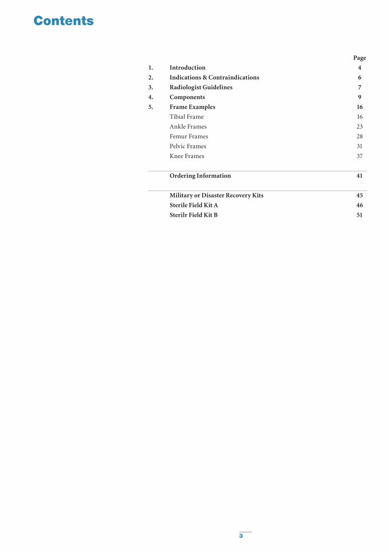
Contents
Page
1. Introduction 4
2. Indications & Contraindications 6
3. Radiologist Guidelines 7
4. Components 9
5. Frame Examples 16
Tibial Frame 16
Ankle Frames 23
Femur Frames 28
Pelvic Frames 31
Knee Frames 37
Ordering Information 41
Military or Disaster Recovery Kits 45
Sterile Field Kit A 46
Sterilr Field Kit B 51

4
In 1938, Raoul Hoffmann, a German-born surgeon living and working in Geneva, Switzerland, set himself the goal of designing a new way to reduce and fix broken bones. His objective was to devise a system that would utilise an alternative form of fracture treatment, without reliance on open surgery. The result was history’s first fully-functional, mainstream External Fixation System1.
The main features of the newly born Hoffmann apparatus were its modular design, its ability to realign, reduce and fix fractures and the pioneering aptitude for making intra and postoperative corrections in all three planes with the frame in situ1. Hoffmann’s closed reduction technique helped establish the very doctrine for minimally invasive orthopaedic surgery while laying the foundation for the Osteotaxis Method, a term that Hoffmann coined himself1.
Over the years, the Hoffmann System has evolved considerably. Today’s completely modular Hoffmann 3 remains faithful to the ingenuity of its inventor.
The Hoffmann 3 is a modular, multiplanar External Fixation System with independent pin placement capabilities, patented6, rapid assembly Snap-Fit Couplings and MR Conditional frame options that are designed to adapt freely to the anatomy to form constructs of high stability for the management of trauma and correction of deformities. It is comprised of a handful of key elements that work in precise agreement to enable surgeons to create a wide variety of frames that allow unhindered access to damaged tissues, permitting rapid and effective treatment of numerous traumatic injuries2,3.
The Hoffmann 3 is not just an update to the earlier renditions of this System; it is the result of comprehensive engineering that has successfully built upon and significantly added to the power, utility and rich legacy of the previous generations.
In the Hoffmann 3 you will find not just a new look, but a demonstrably innovative feel to the entire platform of 11mm based components.
The new generation of fully articulating Delta Couplings promote enhanced stability, greater versatility and unrivalled convenience. The Delta Couplings feature full compatibility with Hoffmann II MRI and even Hoffmann II Compact MRI. That means you can use any combination of 5, 8 and 11mm Connecting Rods in any construct you build. You can rotate all of the Couplings independently to allow numerous provisional options and the freedom to refine your construct throughout the entire surgical procedure.
These same Couplings can be locked securely once definitive reduction and fixation have been achieved. A variety of Pin Clamps allow you to accurately position each pin while an expanded selection of straight and angled posts extends the reach and utility of your frames. This versatile resource of components enables you to build entire constructs that meet the requirements set forth in ASTM (American Society for Testing and Materials) Standards that govern safe usage of medical devices in MRI environments. Compliance with these Standards include all patented6 Vectran coated Connecting Rods, making Stryker both a pioneer and industry leader in MR Conditional External Fixation technology4,6.
Introduction
1. Raoul Hoffmann and His External Fixator, Schwechter, E. M., Swan, K. G.; Published in J Bone Joint Surg Am, Vol. 89, Issue 3, Pages 672 - 678.
2. The Damage control Orthopedic (DCO) Footplate: A New Use of the Hoffmann II External Fixation System. Beck, D.J. Seligson, D. Mereau, T., Published in OsteoTrauma Care 2004, Volume 12, Pages 16 - 19.
3. A Comparison of Two Military Temporary Femoral External Fixators. LTC Paul J. Dougherty, MD; CPT Brian Vickaryous, MD; Edgar Conley, PhD; and Kyle Hickerson, BS; Published in Clinical Orthopaedics and Related Research Number 412, Pages 176 -183
4. Stryker White Paper; Magnetic Resonance Imaging Testing of External Fixation Frames: Stryker Hoffmann II; J. Nyenhuis, PhD.; School of Electrical and Computer Engineering, Purdue University
5. Thermal Response and Torque Resistance of Five Cortical Half Pins Under Simulated Insertion Technique; Wikenheiser, M. A., Market, M. D., Lewallen, D. G., et al., Published in J. Orthop Res 1995; 13; 615 - 619
6. U.S. Patent Nos.: US752,7626, US5,752,954, US6,080,153
5
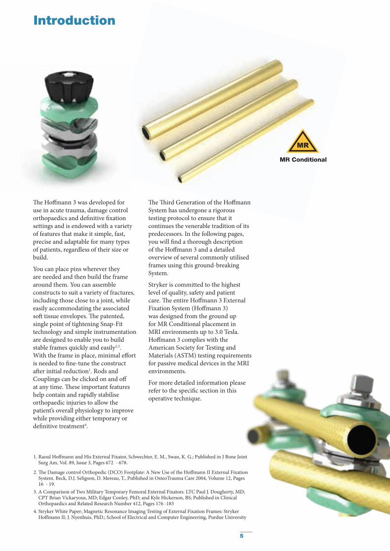
The Hoffmann 3 was developed for use in acute trauma, damage control orthopaedics and definitive fixation settings and is endowed with a variety of features that make it simple, fast, precise and adaptable for many types of patients, regardless of their size or build.
You can place pins wherever they are needed and then build the frame around them. You can assemble constructs to suit a variety of fractures, including those close to a joint, while easily accommodating the associated soft tissue envelopes. The patented, single point of tightening Snap-Fit technology and simple instrumentation are designed to enable you to build stable frames quickly and easily2,3. With the frame in place, minimal effort is needed to fine-tune the construct after initial reduction1. Rods and Couplings can be clicked on and off at any time. These important features help contain and rapidly stabilise orthopaedic injuries to allow the patient’s overall physiology to improve while providing either temporary or definitive treatment4.
The Third Generation of the Hoffmann System has undergone a rigorous testing protocol to ensure that it continues the venerable tradition of its predecessors. In the following pages, you will find a thorough description of the Hoffmann 3 and a detailed overview of several commonly utilised frames using this ground-breaking System.
Stryker is committed to the highest level of quality, safety and patient care. The entire Hoffmann 3 External Fixation System (Hoffmann 3) was designed from the ground up for MR Conditional placement in MRI environments up to 3.0 Tesla. Hoffmann 3 complies with the American Society for Testing and Materials (ASTM) testing requirements for passive medical devices in the MRI environments.
For more detailed information please refer to the specific section in this operative technique.
Introduction
MR ConditionalMR Conditional
1. Raoul Hoffmann and His External Fixator, Schwechter, E. M., Swan, K. G.; Published in J Bone Joint Surg Am, Vol. 89, Issue 3, Pages 672 - 678.
2. The Damage control Orthopedic (DCO) Footplate: A New Use of the Hoffmann II External Fixation System. Beck, D.J. Seligson, D. Mereau, T., Published in OsteoTrauma Care 2004, Volume 12, Pages 16 - 19.
3. A Comparison of Two Military Temporary Femoral External Fixators. LTC Paul J. Dougherty, MD; CPT Brian Vickaryous, MD; Edgar Conley, PhD; and Kyle Hickerson, BS; Published in Clinical Orthopaedics and Related Research Number 412, Pages 176 -183
4. Stryker White Paper; Magnetic Resonance Imaging Testing of External Fixation Frames: Stryker Hoffmann II; J. Nyenhuis, PhD.; School of Electrical and Computer Engineering, Purdue University

6
Indications & Contraindications
The Hoffmann 3 Modular External Fixation System is used to provide stabilization of open and/or unstable fractures and where soft tissue injury may preclude the use of other fracture treatments such as IM rods, casts, or other means of internal fixation.
The Hoffmann 3 Modular External Fixation System components are external fixation frame components for use with the components of the Hoffmann II MRI and Hoffmann II Compact MRI External Fixation Systems, in conjunction with Apex Pins. It is intended to provide stabilization of open and/or unstable fractures and where soft tissue precludes the use of other fracture treatments such as IM nailing or casting or other means of internal fixation.
The indications for use of external fixation devices include:
• Bone Fracture Fixation
• Osteotomy
• Arthrodesis
• Correction of deformity
• Revision procedure where other treatments or devices have been unsuccessful
• Bone reconstruction procedures
ContraindicationsSee package insert for warnings and precautions.
Intended Use Indications

7
Radiologist Guidelines
MRI Components
4922-1-010 4922-1-020 4922-1-030 4922-1-0254922-1-015
4922-2-0204922-2-020 4922-2-320 4922-2-220 4922-1-220 4922-2340
4922-2-120
4921-2-060
4922-2-1604922-2-240 4922-2-1404922-8-XXX 4922-7-220
Note: Frame tests have been performed2 in areas where the greatest temperature increase is expected with commonly used frames. Due to the versatility
of the system, an unlimited number of frames can be built which makes it impossible to test each and every construct. Based on the test results, the Hoffmann 3 may be used in MRI procedures under the specified conditions. There are factors that can influence these results like the number of pins used in the clamps and the number of open and closed loops in the frame. Therefore, it is recommended that each frame be evaluated by a radiologist or MR scientist before the MRI procedure to ensure patient safety. Since different frame configurations and frame sizes might lead to higher temperature increases, Stryker recommends for patient’s safety to minimize SAR settings as much as possible. Non-clinical testing has been performed to rule out the possibility of component movement or migration at static magnetic field strengths higher than 3.0 Tesla or maximum spatial gradients higher than 90.0 mT/cm. MR image quality may be compromised if the area of interest is in the exact same area as or approx. 10cm under worst case conditions to the position of the frame or its individual components.
The MRI components have been tested according to ASTM Standards F2052, F2119, F2182, and F2213.The Hoffmann 3 MRI System can only be guaranteed for MRI use when using Stryker’s Apex Pins to build a frame.
MR Conditional
Stryker is committed to the highest level of quality, safety and patient care. The entire Hoffmann 3 External Fixation System (Hoffmann 3) was designed from the ground up for MR Conditional placement in MRI environments.
Hoffmann 3 complies with the American Society for Testing and Materials (ASTM1) testing requirements for passive medical devices in the MRI environments.
Stryker utilizes a systems approach to address two key areas of concern in MRI use: (1) frame displacement and (2) frame heating.To address these concerns, Hoffmann 3 is designed with non-ferromagnetic materials and insulated carbon rods:• Clamps & couplings are made
from aluminum, austenitic steel and titanium
• Apex® Half Pins and Posts are made from austenitic steel and aluminum
• Carbon-Fiber Rods are coated with an electrically insulating coating, Vectran®
Since Hoffmann 3 components are non-magnetic, magnetic fields in the MRI environment will not displace the frame nor pose a risk of magnetic injury to patients or damage to the scanner if used under proper conditions.
MR ConditionalMR Conditional
1 ASTM F2503-08: http://www.astm.org/Standards/F2503.htm2 Based upon Biomechanical Lab Reports: BML 11-066, BML 11-270, BML 12-061, BML 12-062, Stryker in Selzach, Switzerland
8
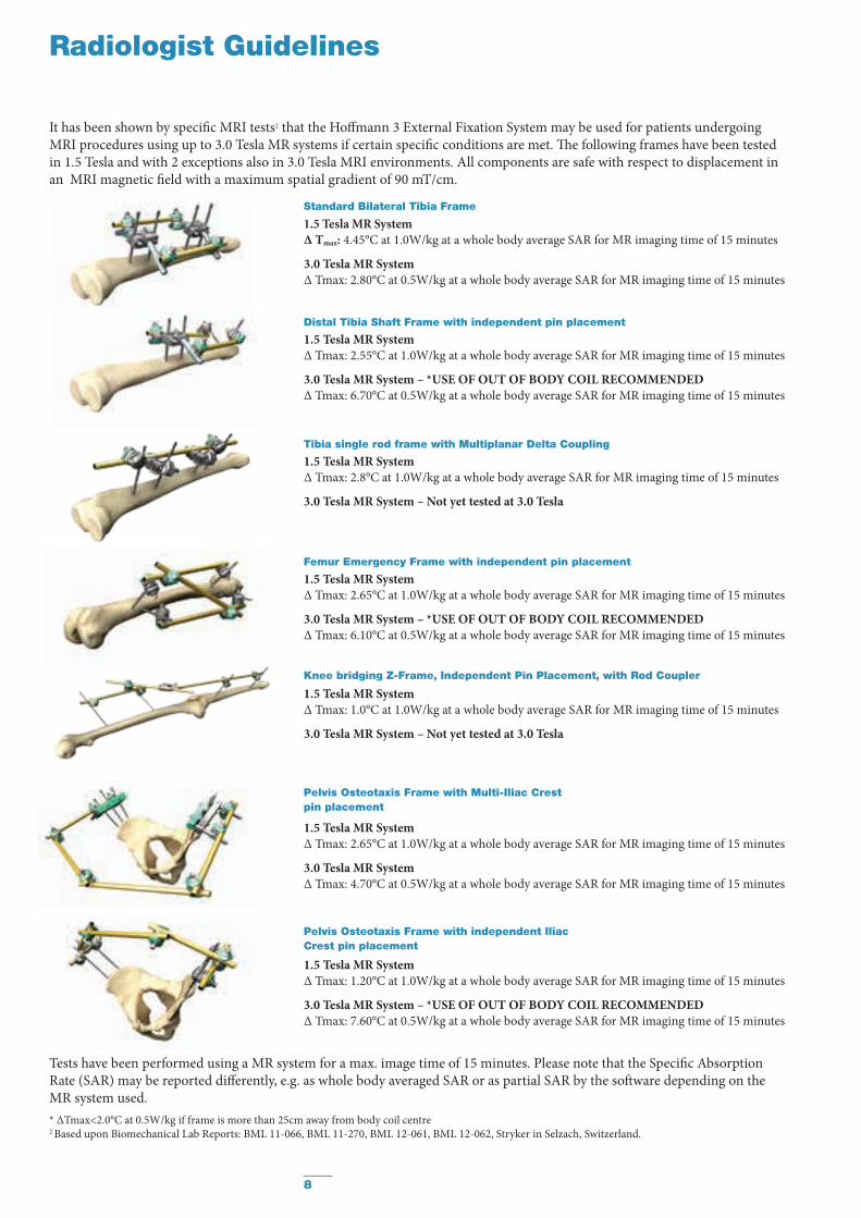
1.5 Tesla MR SystemΔ Tmax: 4.45°C at 1.0W/kg at a whole body average SAR for MR imaging time of 15 minutes
3.0 Tesla MR SystemΔ Tmax: 2.80°C at 0.5W/kg at a whole body average SAR for MR imaging time of 15 minutes
Radiologist Guidelines
Standard Bilateral Tibia Frame
1.5 Tesla MR SystemΔ Tmax: 2.65°C at 1.0W/kg at a whole body average SAR for MR imaging time of 15 minutes
3.0 Tesla MR System – *USE OF OUT OF BODY COIL RECOMMENDEDΔ Tmax: 6.10°C at 0.5W/kg at a whole body average SAR for MR imaging time of 15 minutes
Femur Emergency Frame with independent pin placement
1.5 Tesla MR SystemΔ Tmax: 2.55°C at 1.0W/kg at a whole body average SAR for MR imaging time of 15 minutes
3.0 Tesla MR System – *USE OF OUT OF BODY COIL RECOMMENDEDΔ Tmax: 6.70°C at 0.5W/kg at a whole body average SAR for MR imaging time of 15 minutes
Distal Tibia Shaft Frame with independent pin placement
1.5 Tesla MR SystemΔ Tmax: 1.20°C at 1.0W/kg at a whole body average SAR for MR imaging time of 15 minutes
3.0 Tesla MR System – *USE OF OUT OF BODY COIL RECOMMENDEDΔ Tmax: 7.60°C at 0.5W/kg at a whole body average SAR for MR imaging time of 15 minutes
1.5 Tesla MR SystemΔ Tmax: 2.65°C at 1.0W/kg at a whole body average SAR for MR imaging time of 15 minutes
3.0 Tesla MR SystemΔ Tmax: 4.70°C at 0.5W/kg at a whole body average SAR for MR imaging time of 15 minutes
Pelvis Osteotaxis Frame with Multi-Iliac Crest pin placement
Pelvis Osteotaxis Frame with independent Iliac Crest pin placement
Tests have been performed using a MR system for a max. image time of 15 minutes. Please note that the Specific Absorption Rate (SAR) may be reported differently, e.g. as whole body averaged SAR or as partial SAR by the software depending on the MR system used.
It has been shown by specific MRI tests2 that the Hoffmann 3 External Fixation System may be used for patients undergoingMRI procedures using up to 3.0 Tesla MR systems if certain specific conditions are met. The following frames have been testedin 1.5 Tesla and with 2 exceptions also in 3.0 Tesla MRI environments. All components are safe with respect to displacement in an MRI magnetic field with a maximum spatial gradient of 90 mT/cm.
1.5 Tesla MR SystemΔ Tmax: 2.8°C at 1.0W/kg at a whole body average SAR for MR imaging time of 15 minutes
3.0 Tesla MR System – Not yet tested at 3.0 Tesla
Tibia single rod frame with Multiplanar Delta Coupling
1.5 Tesla MR SystemΔ Tmax: 1.0°C at 1.0W/kg at a whole body average SAR for MR imaging time of 15 minutes
3.0 Tesla MR System – Not yet tested at 3.0 Tesla
Knee bridging Z-Frame, Independent Pin Placement, with Rod Coupler
* ∆Tmax<2.0°C at 0.5W/kg if frame is more than 25cm away from body coil centre2 Based upon Biomechanical Lab Reports: BML 11-066, BML 11-270, BML 12-061, BML 12-062, Stryker in Selzach, Switzerland.

9
Components
Delta CouplingsDesign features for easy frame assembly:• Pre-assembled Thumbwheel for provisional tightening
• Three dimensional rotation
• Patented Snap-fit technology*
Delta Coupling, Rod-to-Rod or Pin-to-Rod
The Rod-to-Rod Delta Couplings can snap onto Ø5, Ø8 or Ø11mm Connecting Rods and Ø5mm Apex Pins**. Rod-to-Rod Delta Couplings are color coded green/green.
Delta Coupling, Pin-to-Rod
The Pin-to-Rod Delta Couplings are designed to fit onto a choice of Ø5, Ø8 or Ø11mm Connecting Rods and Ø4, Ø5 or Ø6mm Apex Pins. Pin-to-Rod Delta Couplings are color coded grey/green.
Delta Coupling, Pin-to-Rod, inverted
‘Inverted’ Pin-to-Rod Delta Coupling are available with the bolt on opposite side to facilitate easy tightening when required by special frame construct accessibility. ‘Inverted’ Pin-to-Rod Delta Couplings are color coded green/grey.
* Patent No’s US5,752,954 and US6,080,153** Note: Standardization with one coupling may be achieved by utilizing
a Rod-to-Rod Delta Coupling with Ø8mm or Ø11mm Connecting Rod and 5mm Apex Pins or 3/5mm, 4/5mm Hybrid Apex Pins.
10
Components
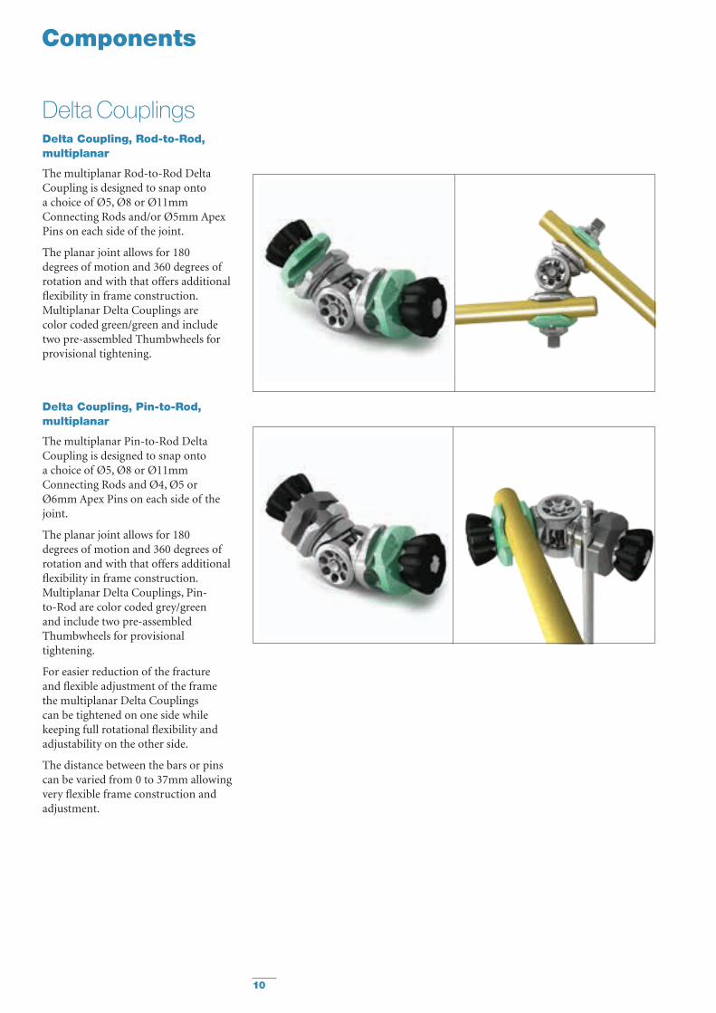
Delta CouplingsDelta Coupling, Rod-to-Rod, multiplanar
The multiplanar Rod-to-Rod Delta Coupling is designed to snap onto a choice of Ø5, Ø8 or Ø11mm Connecting Rods and/or Ø5mm Apex Pins on each side of the joint.
The planar joint allows for 180 degrees of motion and 360 degrees of rotation and with that offers additional flexibility in frame construction. Multiplanar Delta Couplings are color coded green/green and include two pre-assembled Thumbwheels for provisional tightening.
Delta Coupling, Pin-to-Rod, multiplanar
The multiplanar Pin-to-Rod Delta Coupling is designed to snap onto a choice of Ø5, Ø8 or Ø11mm Connecting Rods and Ø4, Ø5 or Ø6mm Apex Pins on each side of the joint.
The planar joint allows for 180 degrees of motion and 360 degrees of rotation and with that offers additional flexibility in frame construction. Multiplanar Delta Couplings, Pin-to-Rod are color coded grey/green and include two pre-assembled Thumbwheels for provisional tightening.
For easier reduction of the fracture and flexible adjustment of the frame the multiplanar Delta Couplings can be tightened on one side while keeping full rotational flexibility and adjustability on the other side.
The distance between the bars or pins can be varied from 0 to 37mm allowing very flexible frame construction and adjustment.
11
Components
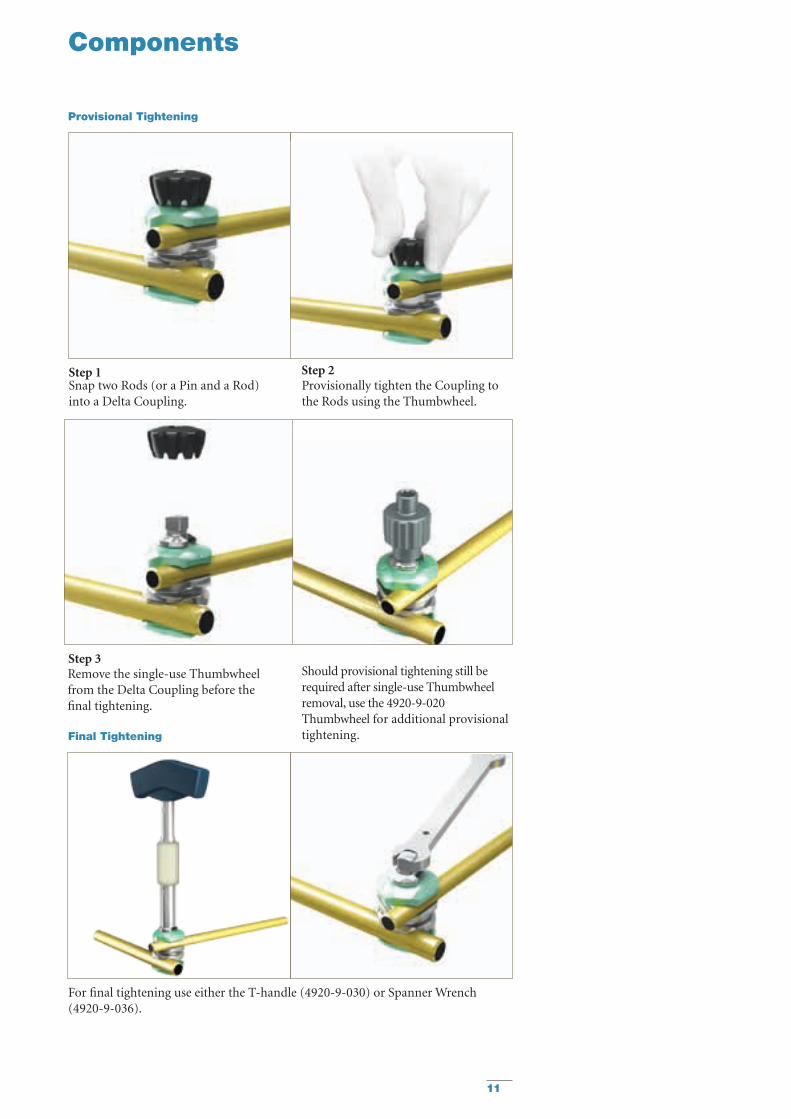
Provisional Tightening
Step 1Snap two Rods (or a Pin and a Rod) into a Delta Coupling.
Step 2Provisionally tighten the Coupling to the Rods using the Thumbwheel.
Step 3 Should provisional tightening still be required after single-use Thumbwheel removal, use the 4920-9-020 Thumbwheel for additional provisional tightening.
Remove the single-use Thumbwheel from the Delta Coupling before the final tightening.
For final tightening use either the T-handle (4920-9-030) or Spanner Wrench (4920-9-036).
Final Tightening
12
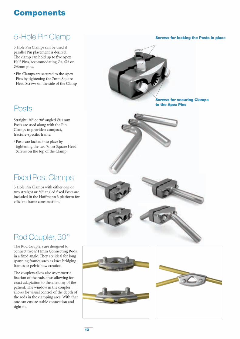
Fixed Post Clamps5 Hole Pin Clamps with either one or two straight or 30° angled fixed Posts are included in the Hoffmann 3 platform for efficient frame construction.
5-Hole Pin Clamp
Components
5 Hole Pin Clamps can be used if parallel Pin placement is desired. The clamp can hold up to five Apex Half Pins, accommodating Ø4, Ø5 or Ø6mm pins.
• Pin Clamps are secured to the Apex Pins by tightening the 7mm Square Head Screws on the side of the Clamp
Screws for locking the Posts in place
Screws for securing Clamps to the Apex PinsPosts
Straight, 30° or 90° angled Ø11mm Posts are used along with the Pin Clamps to provide a compact, fracture-specific frame.
• Posts are locked into place by tightening the two 7mm Square Head Screws on the top of the Clamp
Rod Coupler, 30°The Rod Couplers are designed to connect two Ø11mm Connecting Rods in a fixed angle. They are ideal for long spanning frames such as knee bridging frames or pelvic bow creation.
The couplers allow also asymmetric fixation of the rods, thus allowing for exact adaptation to the anatomy of the patient. The window in the coupler allows for visual control of the depth of the rods in the clamping area. With that one can ensure stable connection and tight fit.

13
Carbon Fiber Vectran coated Connecting Rods, 5, 8 and 11mm optionsStryker provides electrically insulated Carbon Rods for MR Conditional use. The Ø11mm Vectran coated Carbon Connecting Rods are available in lengths from 100mm to 650mm.
The Vectran coated Semi Circular Rods may be used for the fixation of distal femur or proximal and distal tibia (see page 21) fragments.
All Vectran coated Carbon Connecting Rods are intended for Single Patient Use only. Once used on a patient they have to be disposed of. Unused rods can be reprocessed in the tray according to the cleaning and sterilization instructions mentioned in the package insert. Tests have shown intended performance for 50 reprocessing cycles.*
Components
MR Unsafe
MR ConditionalMR Conditional
5, 8 and 11mm Connecting Rod options
* Biomechanical Rest Reports: BML 11-059, BML 12-054
MR Conditional
In addition to the MR Conditional standard system features, the Hoffmann 3 also offers a number of Rod options which are MR Unsafe.
Carbon Fiber Connecting Rods, 5 and 8mm optionsUncoated Carbon Rods offer radiolucency and relative elasticity for light weight constructs.
Stainless Steel Connecting Rods, 5 and 8mm optionsFor fractures requiring more rigidity, stainless steel 5 & 8mm Rods are available.
Aluminium Connecting Rods, 8mm optionAluminium Rods are lightweight and more elastic than the carbon fiber rods.Note:• Carbon fibre material is known to
be effected by steam sterilisation.Hoffmann 3 MR Conditional rods have been tested for multiple sterilisation cycles.
• Frames using one or more MR unsafe components should not be used in the MR Environment.
14
Compatible Components
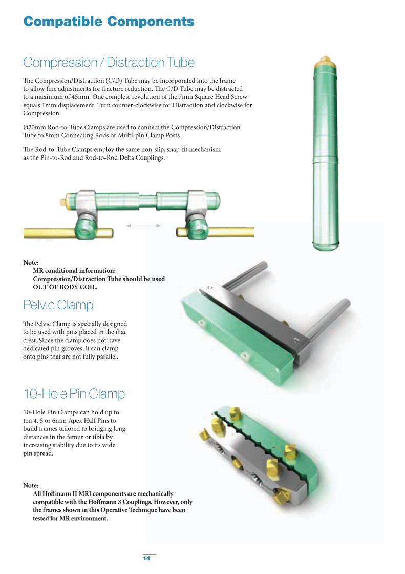
Compression / Distraction TubeThe Compression/Distraction (C/D) Tube may be incorporated into the frame to allow fine adjustments for fracture reduction. The C/D Tube may be distracted to a maximum of 45mm. One complete revolution of the 7mm Square Head Screw equals 1mm displacement. Turn counter-clockwise for Distraction and clockwise for Compression.
Ø20mm Rod-to-Tube Clamps are used to connect the Compression/Distraction Tube to 8mm Connecting Rods or Multi-pin Clamp Posts.
The Rod-to-Tube Clamps employ the same non-slip, snap-fit mechanism as the Pin-to-Rod and Rod-to-Rod Delta Couplings.
The Pelvic Clamp is specially designed to be used with pins placed in the iliac crest. Since the clamp does not have dedicated pin grooves, it can clamp onto pins that are not fully parallel.
10-Hole Pin Clamps can hold up to ten 4, 5 or 6mm Apex Half Pins to build frames tailored to bridging long distances in the femur or tibia by increasing stability due to its wide pin spread.
Pelvic Clamp
10-Hole Pin Clamp
Note: MR conditional information:
Compression/Distraction Tube should be used OUT OF BODY COIL.
Note: All Hoffmann II MRI components are mechanically
compatible with the Hoffmann 3 Couplings. However, only the frames shown in this Operative Technique have been tested for MR environment.
15
Components
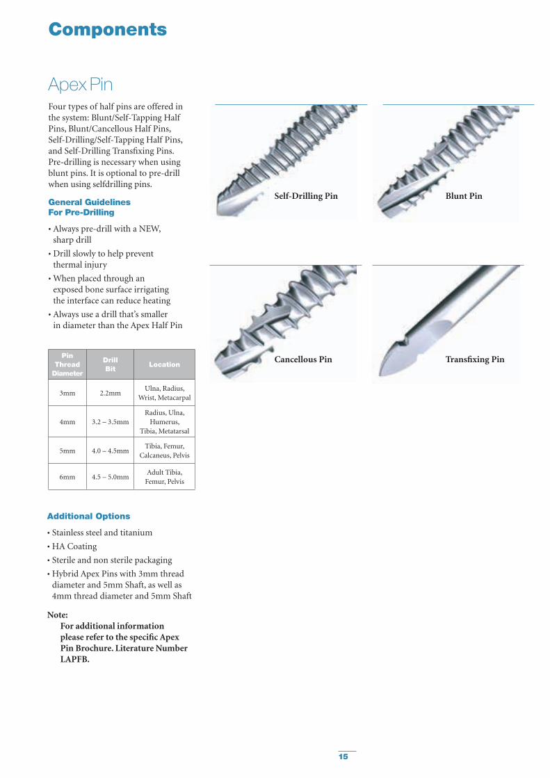
Apex PinFour types of half pins are offered in the system: Blunt/Self-Tapping Half Pins, Blunt/Cancellous Half Pins, Self-Drilling/Self-Tapping Half Pins, and Self-Drilling Transfixing Pins. Pre-drilling is necessary when using blunt pins. It is optional to pre-drill when using selfdrilling pins.
General Guidelines For Pre-Drilling
• Always pre-drill with a NEW, sharp drill
• Drill slowly to help prevent thermal injury
• When placed through an exposed bone surface irrigating the interface can reduce heating
• Always use a drill that’s smaller in diameter than the Apex Half Pin
Pin Thread
Diameter
Drill Bit Location
3mm 2.2mmUlna, Radius,
Wrist, Metacarpal
4mm 3.2 – 3.5mmRadius, Ulna,
Humerus, Tibia, Metatarsal
5mm 4.0 – 4.5mmTibia, Femur,
Calcaneus, Pelvis
6mm 4.5 – 5.0mmAdult Tibia,
Femur, Pelvis
Blunt Pin
Cancellous Pin Transfixing Pin
Self-Drilling Pin
Additional Options
• Stainless steel and titanium
• HA Coating
• Sterile and non sterile packaging
• Hybrid Apex Pins with 3mm thread diameter and 5mm Shaft, as well as 4mm thread diameter and 5mm Shaft
Note: For additional information
please refer to the specific Apex Pin Brochure. Literature Number LAPFB.
16
Tibial Frames
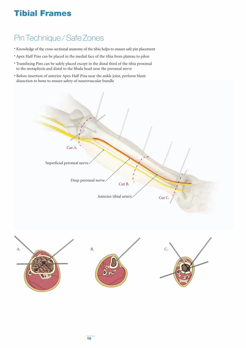
Pin Technique / Safe Zones• Knowledge of the cross-sectional anatomy of the tibia helps to ensure safe pin placement
• Apex Half Pins can be placed in the medial face of the tibia from plateau to pilon
• Transfixing Pins can be safely placed except in the distal third of the tibia proximal to the metaphysis and distal to the fibula head near the peroneal nerve
• Before insertion of anterior Apex Half Pins near the ankle joint, perform blunt dissection to bone to ensure safety of neurovascular bundle
Superficial peroneal nerve
Deep peroneal nerve
Anterior tibial artery
Cut A.
Cut B.
Cut C.
A. B. C.

17
Tibial Frames
Tibial Single Rod FrameIndependent Pin Placement, with multiplanar Delta Couplings
Components List REF Description Quantity
4922-1-025 Pin-to-Rod Delta Coupling, multiplanar 24922-1-020 Pin-to-Rod Delta Coupling 25018-5-150 Apex Pin Ø5 x 150mm 44922-8-300 Connecting Rods Ø11 x 300mm 1

18
Note: Alternatively the Pin-to-Rod Delta Couplings can be replaced by mulitplanar
Pin-to-Rod Delta Couplings, thus offering more flexibility and freedom when placing the Apex Pins and when reducing the fracture before final tightening.
Tibial Frames
Tibial Standard Bi-lateral FrameParallel Pin Placement
Components List REF Description Quantity
4922-2-020 5-Hole Pin Clamp 24922-2-140 30° Angled Post Ø11mm 44922-1-010 Rod-to-Rod Delta Coupling 45018-5-150 Apex Pin Ø5 x 150mm 44922-8-300 Connecting Rods Ø11 x 300mm 2
19
Tibial Frames
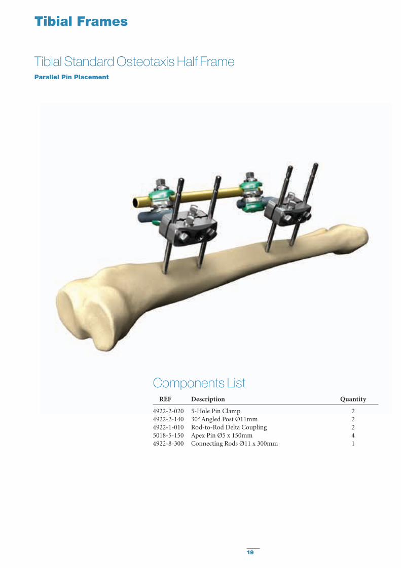
Tibial Standard Osteotaxis Half FrameParallel Pin Placement
Components List REF Description Quantity
4922-2-020 5-Hole Pin Clamp 24922-2-140 30° Angled Post Ø11mm 24922-1-010 Rod-to-Rod Delta Coupling 25018-5-150 Apex Pin Ø5 x 150mm 44922-8-300 Connecting Rods Ø11 x 300mm 1

20
Tibial Frames
Tibial Plateau Semi-Circular FrameParallel/Independent Pin Placement
Components List REF Description Quantity
4922-2-020 5-Hole Pin Clamp 14922-2-140 30° Angled Post Ø11mm 24922-1-010 Rod-to-Rod Delta Coupling 54922-1-020 Pin-to-Rod Delta Coupling 24922-1-030 Pin-to-Rod Delta Coupling, inverted 25018-5-150 Apex Pin Ø5 x 150mm 54922-7-220 Semi Circular Rod Ø11 x 220mm 14922-8-300 Connecting Rods Ø11 x 300mm 3

21
Tibial Frames
Distal Tibia Semi-Circular FrameParallel/Independent Pin Placement
Components List REF Description Quantity
4922-2-020 5-Hole Pin Clamp 14922-2-140 30° Angled Post Ø11mm 2 4922-1-010 Rod-to-Rod Delta Coupling 44922-1-020 Pin-to-Rod Delta Coupling 34922-1-030 Pin-to-Rod Delta Coupling inverted
(alternatively 1)5018-5-150 Apex Pin Ø5 x 150mm 55028-7-030 Semi-Circular Rod Ø8mm 14922-8-300 Connecting Rods Ø11 x 300mm 2
22
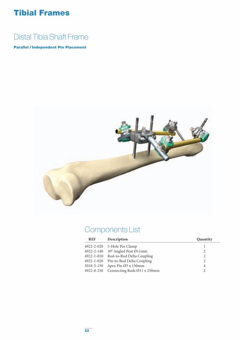
Tibial Frames
Distal Tibia Shaft FrameParallel / Independent Pin Placement
Components List REF Description Quantity
4922-2-020 5-Hole Pin Clamp 14922-2-140 30° Angled Post Ø11mm 2 4922-1-010 Rod-to-Rod Delta Coupling 24922-1-020 Pin-to-Rod Delta Coupling 25018-5-150 Apex Pin Ø5 x 150mm 4 4922-8-250 Connecting Rods Ø11 x 250mm 2
23
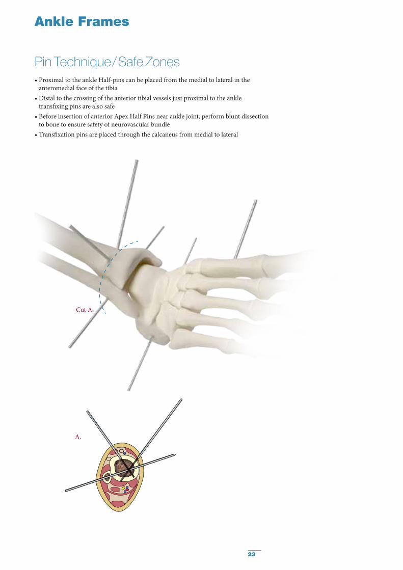
Ankle Frames
Pin Technique / Safe Zones• Proximal to the ankle Half-pins can be placed from the medial to lateral in the
anteromedial face of the tibia• Distal to the crossing of the anterior tibial vessels just proximal to the ankle
transfixing pins are also safe• Before insertion of anterior Apex Half Pins near ankle joint, perform blunt dissection
to bone to ensure safety of neurovascular bundle• Transfixation pins are placed through the calcaneus from medial to lateral
Cut A.
A.
24
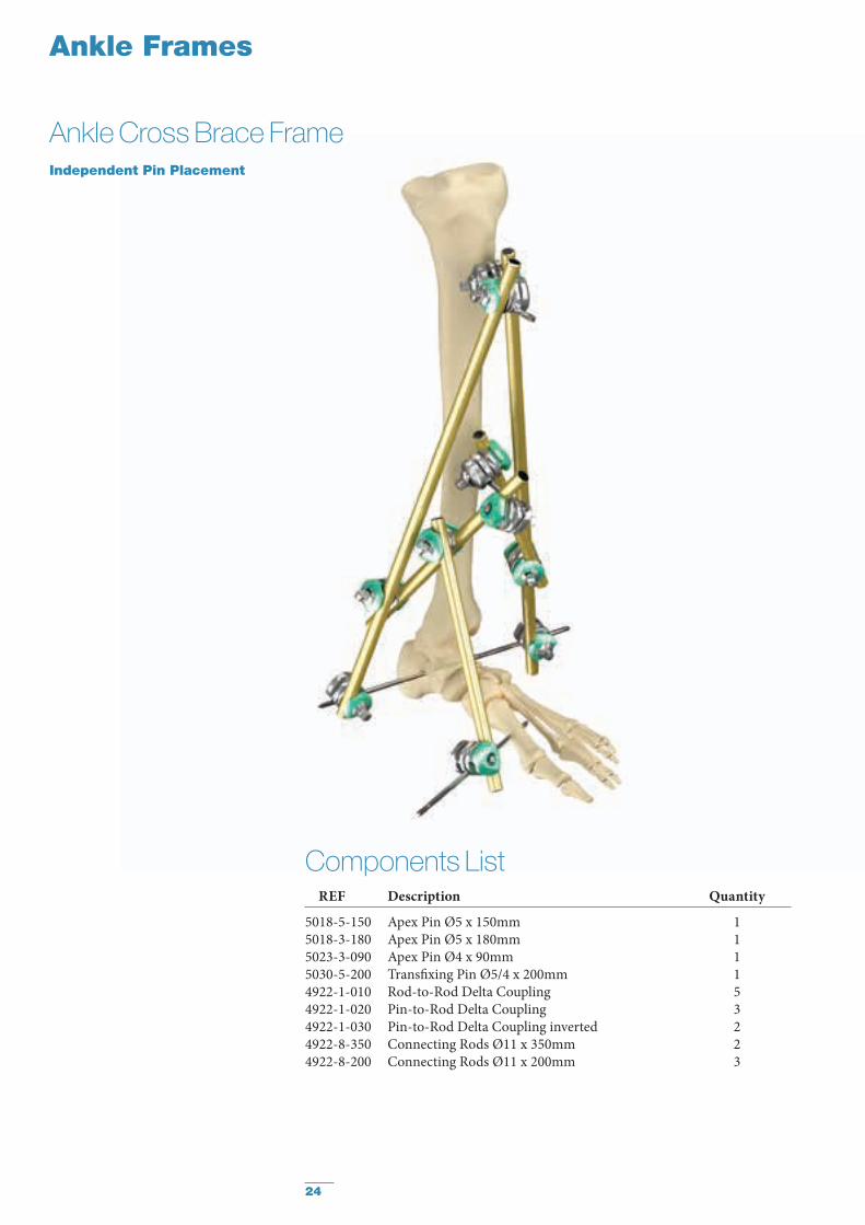
Ankle Frames
Ankle Cross Brace FrameIndependent Pin Placement
Components List REF Description Quantity
5018-5-150 Apex Pin Ø5 x 150mm 1 5018-3-180 Apex Pin Ø5 x 180mm 1 5023-3-090 Apex Pin Ø4 x 90mm 15030-5-200 Transfixing Pin Ø5/4 x 200mm 1 4922-1-010 Rod-to-Rod Delta Coupling 54922-1-020 Pin-to-Rod Delta Coupling 34922-1-030 Pin-to-Rod Delta Coupling inverted 24922-8-350 Connecting Rods Ø11 x 350mm 24922-8-200 Connecting Rods Ø11 x 200mm 3

25
Ankle Frames
Ankle Bridging FrameParallel Pin Placement
Components List REF Description Quantity
4922-2-020 5-Hole Pin Clamp 34922-2-140 30° Angled Post Ø11mm 24922-2-120 Straight Post Ø11mm 24922-1-010 Rod-to-Rod Delta Coupling 45018-5-150 Apex Pin Ø5 x 150mm 25030-5-200 Transfixing Pin Ø5/4 x 200mm 24922-8-250 Connecting Rods Ø11 x 250mm 2
26
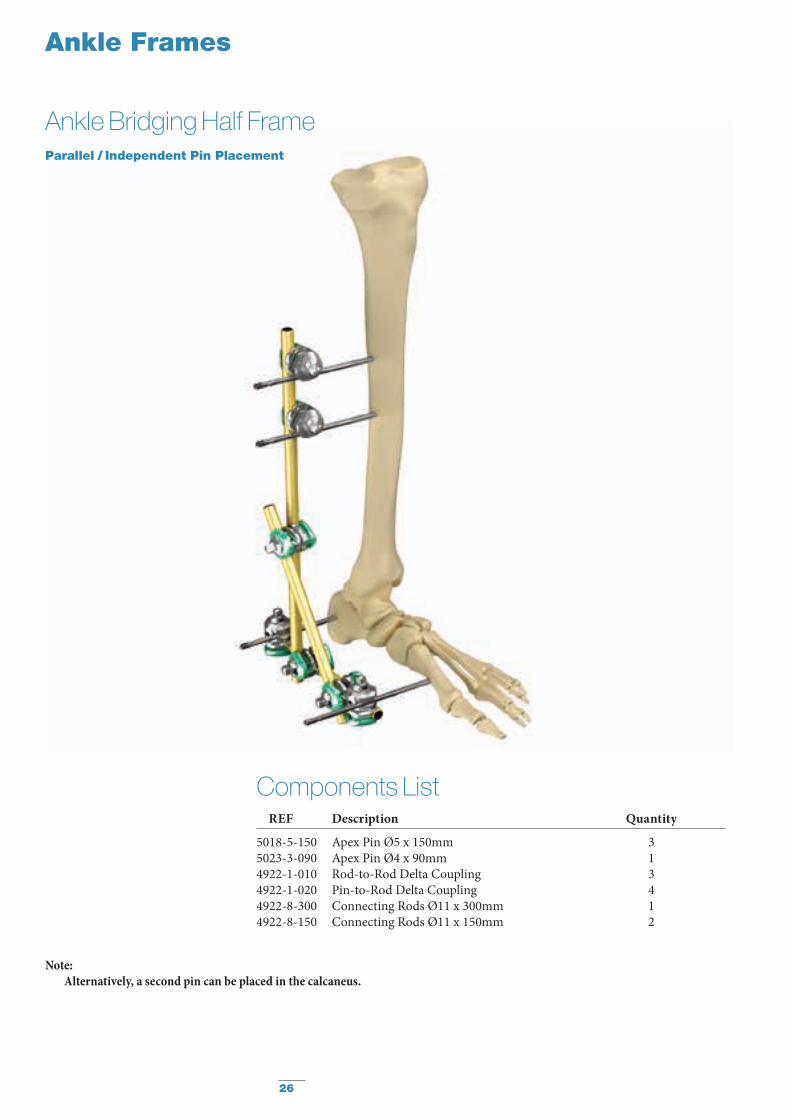
Ankle Frames
Ankle Bridging Half FrameParallel / Independent Pin Placement
Note:Alternatively, a second pin can be placed in the calcaneus.
Components List REF Description Quantity
5018-5-150 Apex Pin Ø5 x 150mm 3 5023-3-090 Apex Pin Ø4 x 90mm 14922-1-010 Rod-to-Rod Delta Coupling 34922-1-020 Pin-to-Rod Delta Coupling 44922-8-300 Connecting Rods Ø11 x 300mm 14922-8-150 Connecting Rods Ø11 x 150mm 2

27
Ankle Frames
Ankle Stabilization FrameIndependent Pin Placement
Components List REF Description Quantity
5018-5-150 Apex Pin Ø5 x 150mm 2 5023-3-090 Apex Pin Ø4 x 90mm 1 4922-1-010 Rod-to-Rod Delta Coupling 34922-1-020 Pin-to-Rod Delta Coupling 34922-8-250 Connecting Rods Ø11 x 250mm 24922-8-100 Connecting Rods Ø11 x 100mm 1
28
Femur Frames
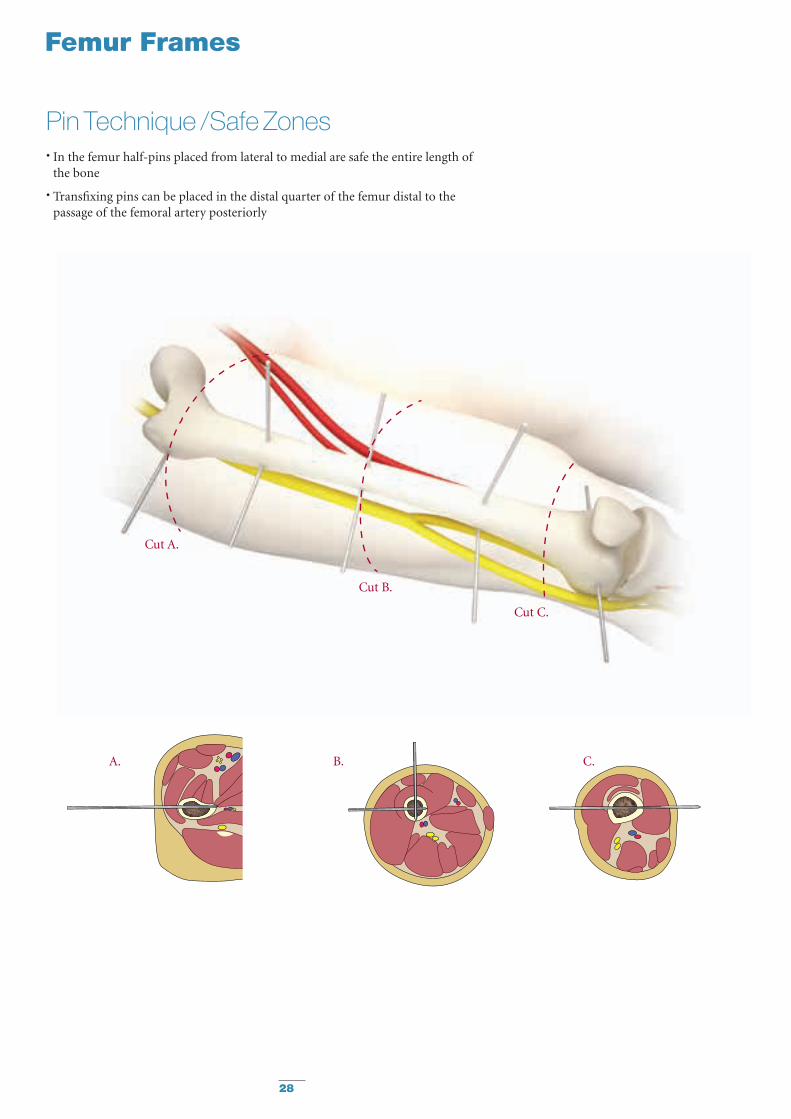
Pin Technique / Safe Zones• In the femur half-pins placed from lateral to medial are safe the entire length of
the bone
• Transfixing pins can be placed in the distal quarter of the femur distal to the passage of the femoral artery posteriorly
Cut A.
Cut B.
Cut C.
A. B. C.
29
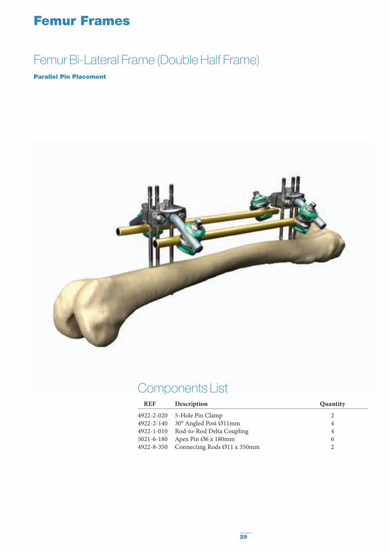
Femur Frames
Femur Bi-Lateral Frame (Double Half Frame)Parallel Pin Placement
Components List REF Description Quantity
4922-2-020 5-Hole Pin Clamp 24922-2-140 30° Angled Post Ø11mm 44922-1-010 Rod-to-Rod Delta Coupling 45021-6-180 Apex Pin Ø6 x 180mm 64922-8-350 Connecting Rods Ø11 x 350mm 2

30
Femur Frames
Femur Emergency FrameIndependent Pin Placement
Note: Apply additional pins and rods
before patient transportation.
Components List REF Description Quantity
4922-1-020 Pin-to-Rod Delta Coupling 44922-1-010 Rod-to-Rod Delta Coupling 25021-6-180 Apex Pin Ø6 x 180mm 44922-8-350 Connecting Rods Ø11 x 350mm 3
31
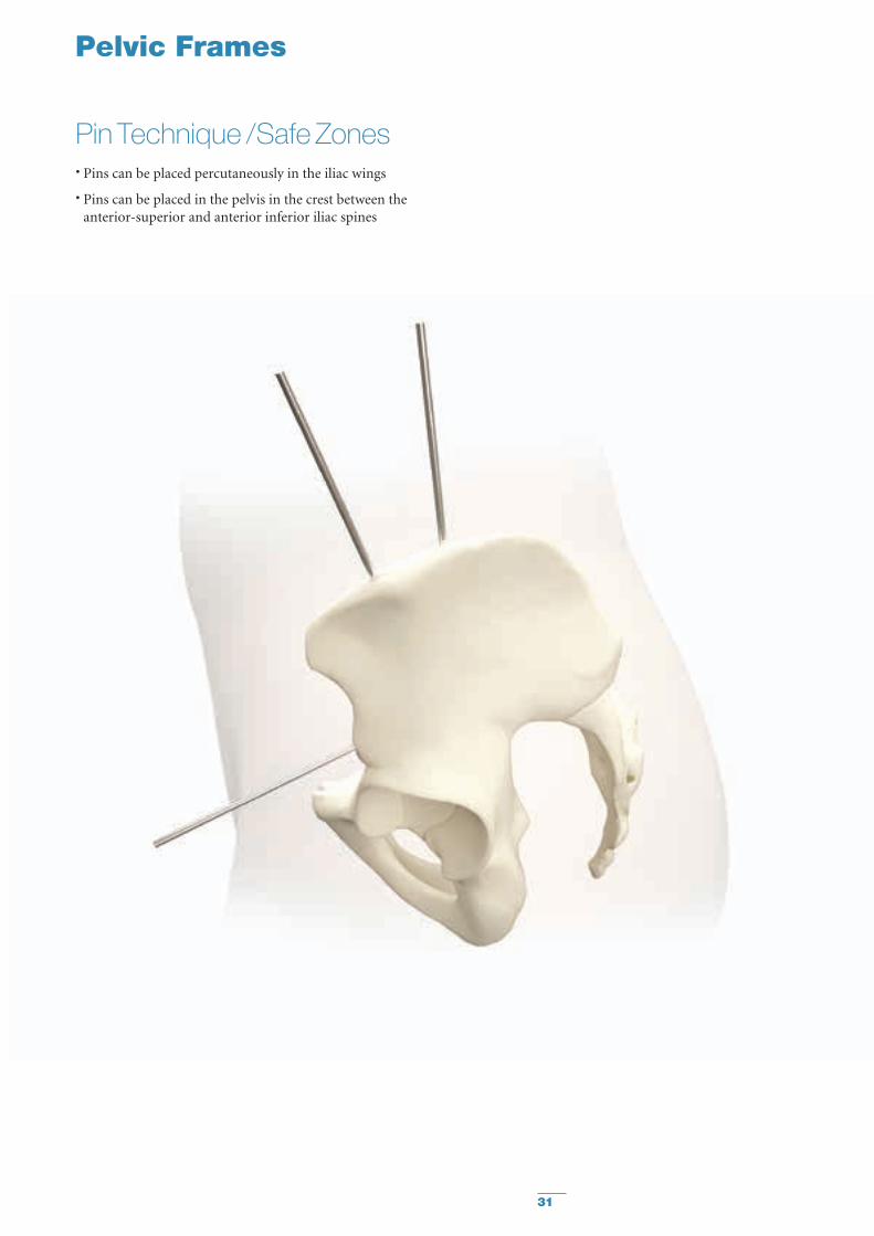
Pelvic Frames
Pin Technique / Safe Zones• Pins can be placed percutaneously in the iliac wings
• Pins can be placed in the pelvis in the crest between the anterior-superior and anterior inferior iliac spines
32
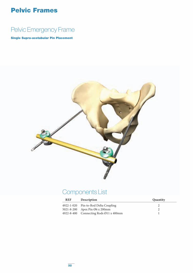
Pelvic Frames
Pelvic Emergency FrameSingle Supra-acetabular Pin Placement
Components List REF Description Quantity
4922-1-020 Pin-to-Rod Delta Coupling 25021-8-200 Apex Pin Ø6 x 200mm 24922-8-400 Connecting Rods Ø11 x 400mm 1
33
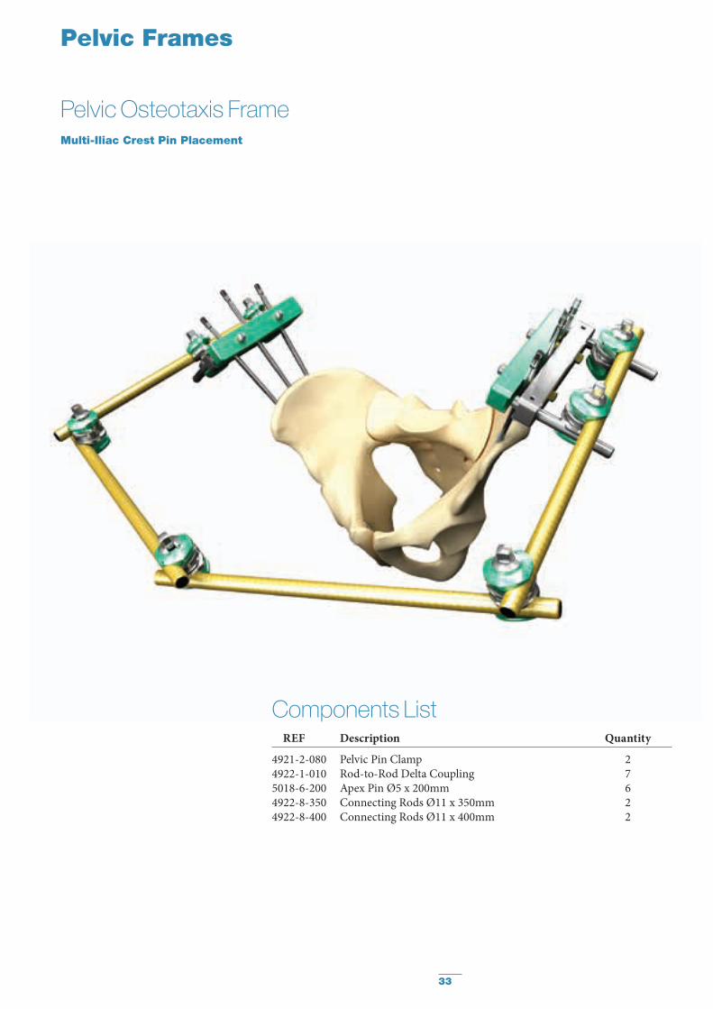
Pelvic Frames
Pelvic Osteotaxis FrameMulti-Iliac Crest Pin Placement
Components List REF Description Quantity
4921-2-080 Pelvic Pin Clamp 24922-1-010 Rod-to-Rod Delta Coupling 75018-6-200 Apex Pin Ø5 x 200mm 64922-8-350 Connecting Rods Ø11 x 350mm 24922-8-400 Connecting Rods Ø11 x 400mm 2
34
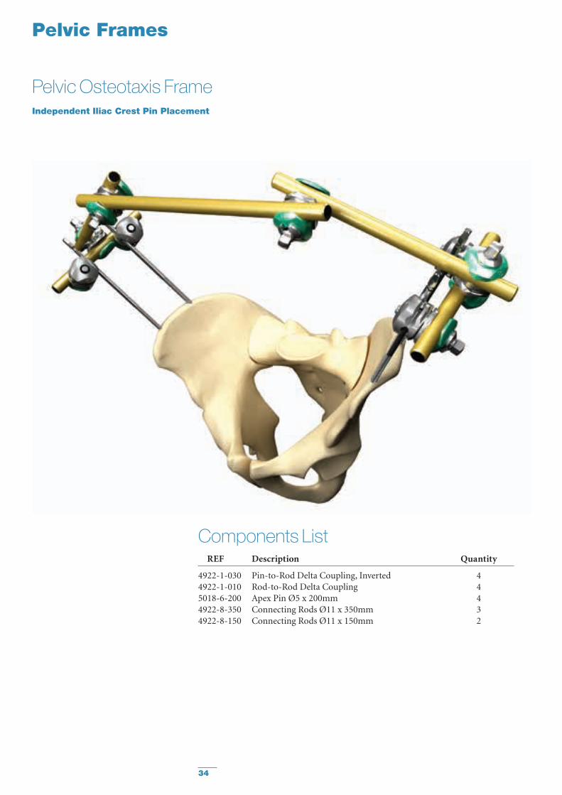
Pelvic Frames
Pelvic Osteotaxis FrameIndependent Iliac Crest Pin Placement
Components List REF Description Quantity
4922-1-030 Pin-to-Rod Delta Coupling, Inverted 44922-1-010 Rod-to-Rod Delta Coupling 45018-6-200 Apex Pin Ø5 x 200mm 44922-8-350 Connecting Rods Ø11 x 350mm 34922-8-150 Connecting Rods Ø11 x 150mm 2
35
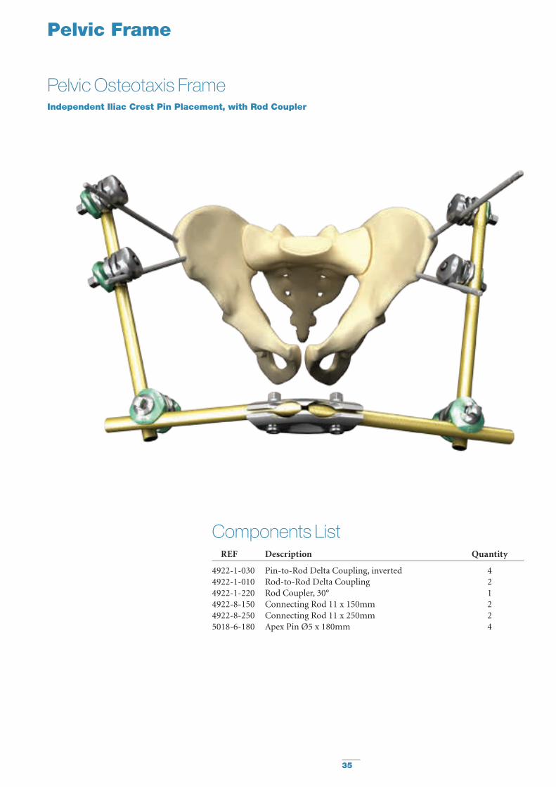
Pelvic Frame
Pelvic Osteotaxis FrameIndependent Iliac Crest Pin Placement, with Rod Coupler
Components List REF Description Quantity
4922-1-030 Pin-to-Rod Delta Coupling, inverted 44922-1-010 Rod-to-Rod Delta Coupling 24922-1-220 Rod Coupler, 30° 14922-8-150 Connecting Rod 11 x 150mm 24922-8-250 Connecting Rod 11 x 250mm 25018-6-180 Apex Pin Ø5 x 180mm 4
36
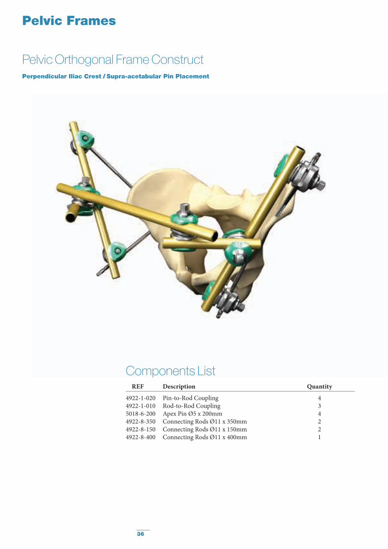
Pelvic Frames
Pelvic Orthogonal Frame ConstructPerpendicular Iliac Crest / Supra-acetabular Pin Placement
Components List REF Description Quantity
4922-1-020 Pin-to-Rod Coupling 44922-1-010 Rod-to-Rod Coupling 35018-6-200 Apex Pin Ø5 x 200mm 44922-8-350 Connecting Rods Ø11 x 350mm 24922-8-150 Connecting Rods Ø11 x 150mm 24922-8-400 Connecting Rods Ø11 x 400mm 1
37
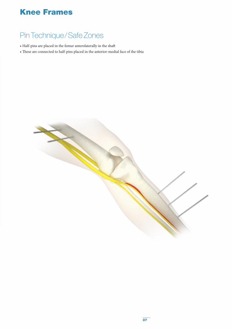
Knee Frames
Pin Technique / Safe Zones• Half-pins are placed in the femur anterolaterally in the shaft• These are connected to half-pins placed in the anterior-medial face of the tibia
38
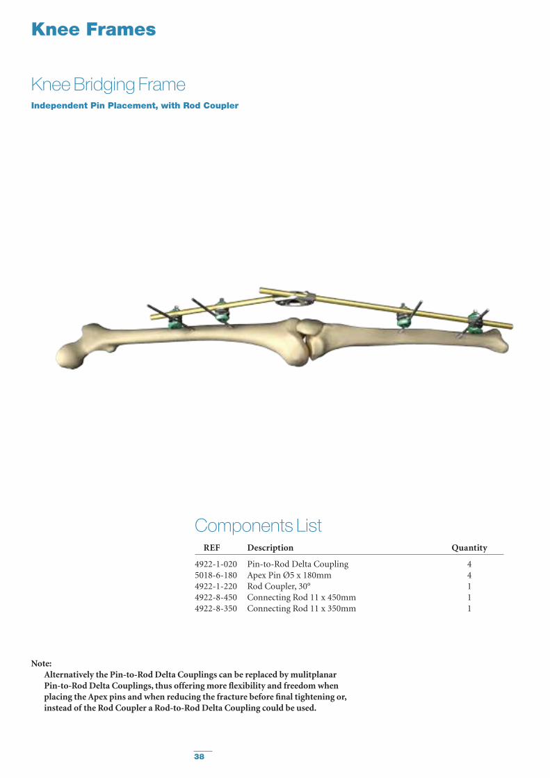
Knee Frames
Knee Bridging FrameIndependent Pin Placement, with Rod Coupler
Components List REF Description Quantity
4922-1-020 Pin-to-Rod Delta Coupling 4 5018-6-180 Apex Pin Ø5 x 180mm 44922-1-220 Rod Coupler, 30° 14922-8-450 Connecting Rod 11 x 450mm 1 4922-8-350 Connecting Rod 11 x 350mm 1
Note: Alternatively the Pin-to-Rod Delta Couplings can be replaced by mulitplanar
Pin-to-Rod Delta Couplings, thus offering more flexibility and freedom when placing the Apex pins and when reducing the fracture before final tightening or, instead of the Rod Coupler a Rod-to-Rod Delta Coupling could be used.
39
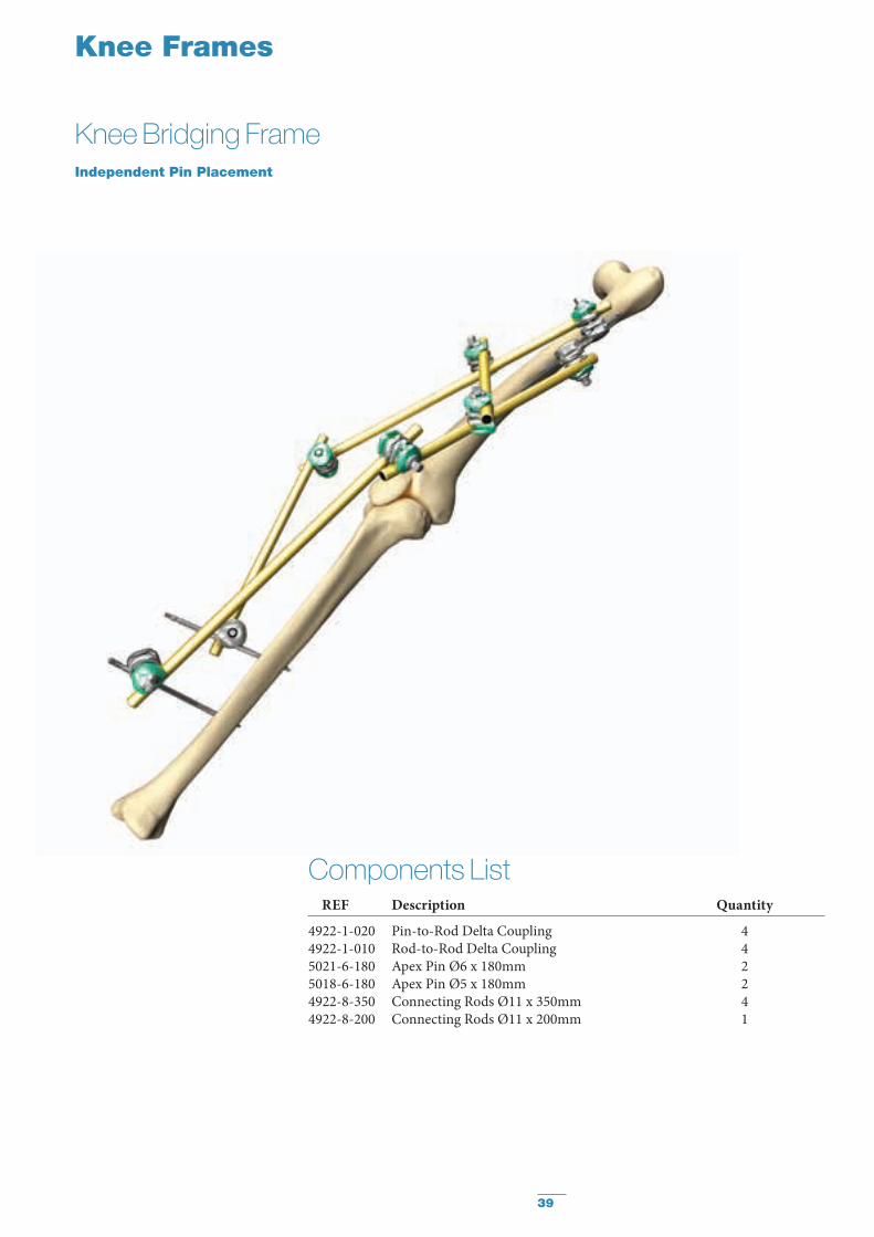
Knee Frames
Knee Bridging FrameIndependent Pin Placement
Components List REF Description Quantity
4922-1-020 Pin-to-Rod Delta Coupling 44922-1-010 Rod-to-Rod Delta Coupling 45021-6-180 Apex Pin Ø6 x 180mm 25018-6-180 Apex Pin Ø5 x 180mm 24922-8-350 Connecting Rods Ø11 x 350mm 44922-8-200 Connecting Rods Ø11 x 200mm 1

40
Knee Frames
Knee Bridging Z-FrameIndependent Pin Placement, with Rod Coupler
Components List REF Description Quantity
4922-1-020 Pin-to-Rod Delta Coupling 44922-1-010 Rod-to-Rod Delta Coupling 15018-6-180 Apex Pin Ø5 x 180mm 44922-1-220 Rod Coupler, 30° 14922-8-400 Connecting Rod 11 x 400mm 24922-8-250 Connecting Rod 11 x 250mm 1
Note: Alternatively the Pin-to-Rod Delta Couplings can be replaced by mulitplanar
Pin-to-Rod Delta Couplings, thus offering more flexibility and freedom when placing the Apex Pins and when reducing the fracture before final tightening. Or, instead of the Rod Coupler a Rod-to-Rod Delta Coupling could be used.
41
MR Conditional
MR Conditional
MR Conditional
Ordering Information
REF Description
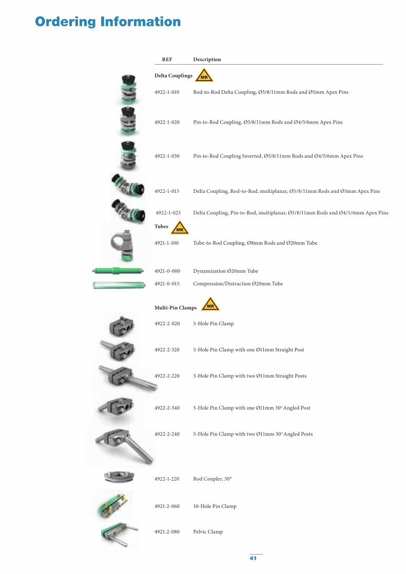
Delta Couplings
4922-1-010 Rod-to-Rod Delta Coupling, Ø5/8/11mm Rods and Ø5mm Apex Pins
4922-1-020 Pin-to-Rod Coupling, Ø5/8/11mm Rods and Ø4/5/6mm Apex Pins
4922-1-030 Pin-to-Rod Coupling Inverted, Ø5/8/11mm Rods and Ø4/5/6mm Apex Pins
4922-1-015 Delta Coupling, Rod-to-Rod, multiplanar, Ø5/8/11mm Rods and Ø5mm Apex Pins
4922-1-025 Delta Coupling, Pin-to-Rod, multiplanar, Ø5/8/11mm Rods and Ø4/5/6mm Apex Pins
Tubes
4921-1-100 Tube-to-Rod Coupling, Ø8mm Rods and Ø20mm Tube
4921-0-000 Dynamization Ø20mm Tube
4921-0-015 Compression/Distraction Ø20mm Tube
Multi-Pin Clamps
4922-2-020 5-Hole Pin Clamp
4922-2-320 5-Hole Pin Clamp with one Ø11mm Straight Post
4922-2-220 5-Hole Pin Clamp with two Ø11mm Straight Posts
4922-2-340 5-Hole Pin Clamp with one Ø11mm 30o Angled Post
4922-2-240 5-Hole Pin Clamp with two Ø11mm 30o Angled Posts
4922-1-220 Rod Coupler, 30°
4921-2-060 10-Hole Pin Clamp
4921-2-080 Pelvic Clamp
42
Ordering Information
REF Description
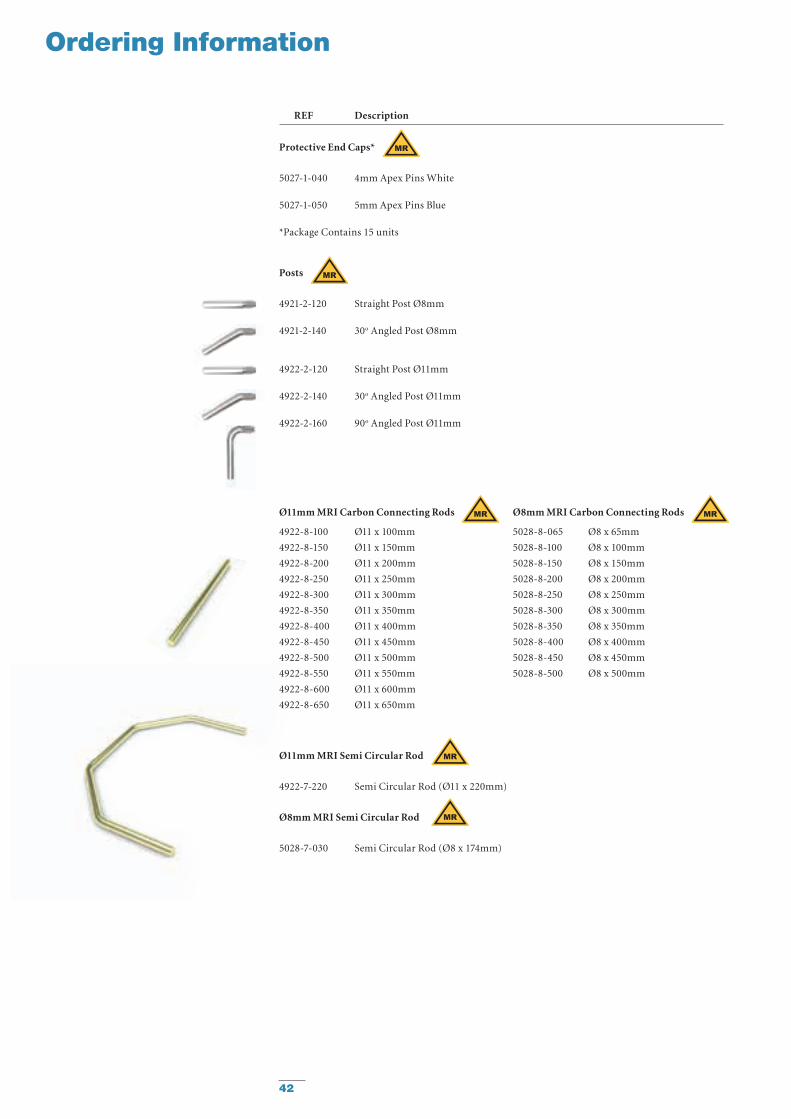
Posts
4921-2-120 Straight Post Ø8mm
4921-2-140 30o Angled Post Ø8mm
4922-2-120 Straight Post Ø11mm
4922-2-140 30o Angled Post Ø11mm
4922-2-160 90o Angled Post Ø11mm
Protective End Caps*
5027-1-040 4mm Apex Pins White
5027-1-050 5mm Apex Pins Blue
*Package Contains 15 units
Ø11mm MRI Carbon Connecting Rods
4922-8-100 Ø11 x 100mm
4922-8-150 Ø11 x 150mm
4922-8-200 Ø11 x 200mm
4922-8-250 Ø11 x 250mm
4922-8-300 Ø11 x 300mm
4922-8-350 Ø11 x 350mm
4922-8-400 Ø11 x 400mm
4922-8-450 Ø11 x 450mm
4922-8-500 Ø11 x 500mm
4922-8-550 Ø11 x 550mm
4922-8-600 Ø11 x 600mm
4922-8-650 Ø11 x 650mm
Ø8mm MRI Carbon Connecting Rods
5028-8-065 Ø8 x 65mm
5028-8-100 Ø8 x 100mm
5028-8-150 Ø8 x 150mm
5028-8-200 Ø8 x 200mm
5028-8-250 Ø8 x 250mm
5028-8-300 Ø8 x 300mm
5028-8-350 Ø8 x 350mm
5028-8-400 Ø8 x 400mm
5028-8-450 Ø8 x 450mm
5028-8-500 Ø8 x 500mm
Ø11mm MRI Semi Circular Rod
4922-7-220 Semi Circular Rod (Ø11 x 220mm)
Ø8mm MRI Semi Circular Rod
5028-7-030 Semi Circular Rod (Ø8 x 174mm)
MR Conditional
MR Conditional
MR Conditional MR Conditional
MR Conditional
MR Conditional
43
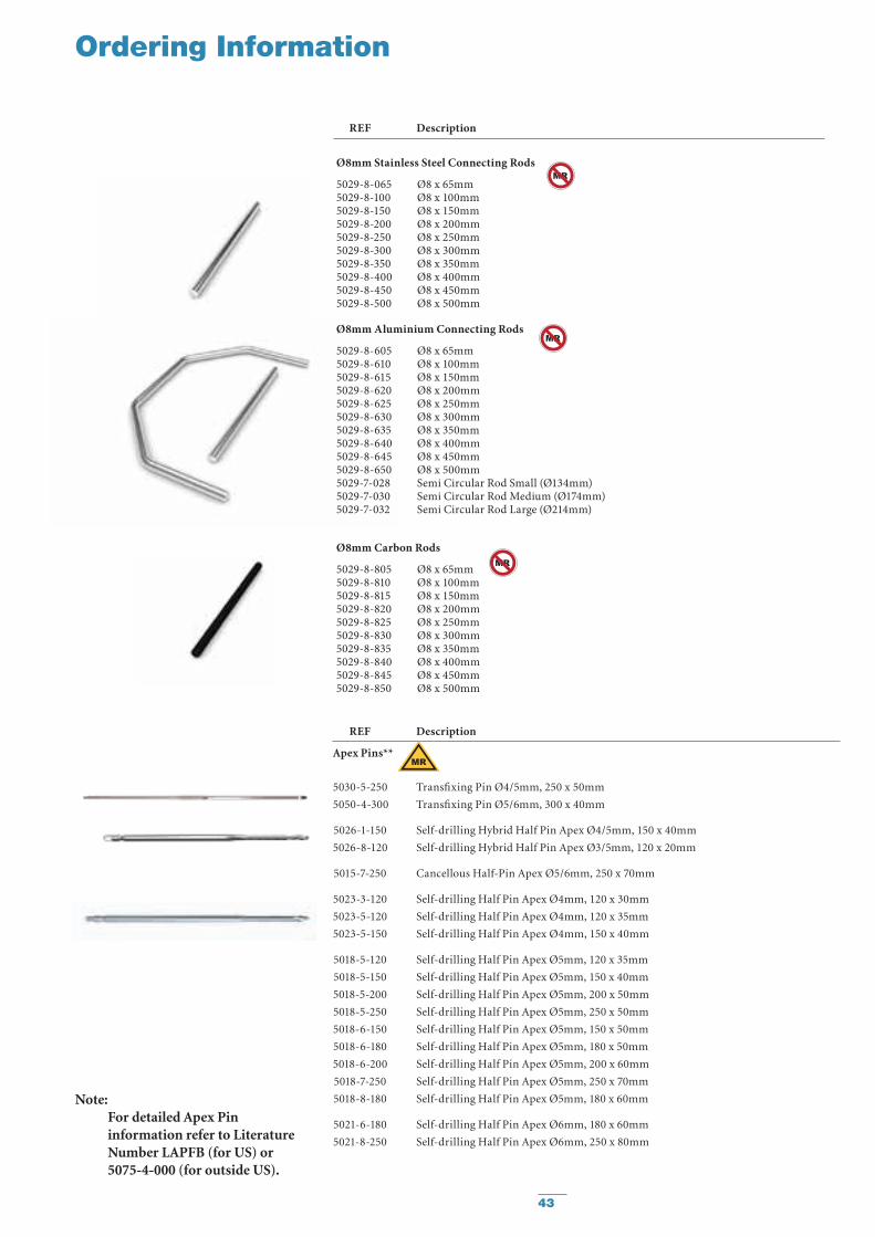
Ø8mm Stainless Steel Connecting Rods
5029-8-065 Ø8 x 65mm 5029-8-100 Ø8 x 100mm 5029-8-150 Ø8 x 150mm 5029-8-200 Ø8 x 200mm 5029-8-250 Ø8 x 250mm 5029-8-300 Ø8 x 300mm 5029-8-350 Ø8 x 350mm 5029-8-400 Ø8 x 400mm 5029-8-450 Ø8 x 450mm 5029-8-500 Ø8 x 500mm
Ø8mm Aluminium Connecting Rods
5029-8-605 Ø8 x 65mm 5029-8-610 Ø8 x 100mm 5029-8-615 Ø8 x 150mm 5029-8-620 Ø8 x 200mm 5029-8-625 Ø8 x 250mm 5029-8-630 Ø8 x 300mm 5029-8-635 Ø8 x 350mm 5029-8-640 Ø8 x 400mm 5029-8-645 Ø8 x 450mm 5029-8-650 Ø8 x 500mm 5029-7-028 Semi Circular Rod Small (Ø134mm) 5029-7-030 Semi Circular Rod Medium (Ø174mm) 5029-7-032 Semi Circular Rod Large (Ø214mm)
Ø8mm Carbon Rods
5029-8-805 Ø8 x 65mm 5029-8-810 Ø8 x 100mm 5029-8-815 Ø8 x 150mm 5029-8-820 Ø8 x 200mm 5029-8-825 Ø8 x 250mm 5029-8-830 Ø8 x 300mm 5029-8-835 Ø8 x 350mm 5029-8-840 Ø8 x 400mm 5029-8-845 Ø8 x 450mm 5029-8-850 Ø8 x 500mm
MR Conditional
MR Conditional
MR Conditional
REF Description
Ordering Information
REF Description
Apex Pins**
5030-5-250 Transfixing Pin Ø4/5mm, 250 x 50mm
5050-4-300 Transfixing Pin Ø5/6mm, 300 x 40mm
5026-1-150 Self-drilling Hybrid Half Pin Apex Ø4/5mm, 150 x 40mm
5026-8-120 Self-drilling Hybrid Half Pin Apex Ø3/5mm, 120 x 20mm
5015-7-250 Cancellous Half-Pin Apex Ø5/6mm, 250 x 70mm
5023-3-120 Self-drilling Half Pin Apex Ø4mm, 120 x 30mm
5023-5-120 Self-drilling Half Pin Apex Ø4mm, 120 x 35mm
5023-5-150 Self-drilling Half Pin Apex Ø4mm, 150 x 40mm
5018-5-120 Self-drilling Half Pin Apex Ø5mm, 120 x 35mm
5018-5-150 Self-drilling Half Pin Apex Ø5mm, 150 x 40mm
5018-5-200 Self-drilling Half Pin Apex Ø5mm, 200 x 50mm
5018-5-250 Self-drilling Half Pin Apex Ø5mm, 250 x 50mm
5018-6-150 Self-drilling Half Pin Apex Ø5mm, 150 x 50mm
5018-6-180 Self-drilling Half Pin Apex Ø5mm, 180 x 50mm
5018-6-200 Self-drilling Half Pin Apex Ø5mm, 200 x 60mm
5018-7-250 Self-drilling Half Pin Apex Ø5mm, 250 x 70mm
5018-8-180 Self-drilling Half Pin Apex Ø5mm, 180 x 60mm
5021-6-180 Self-drilling Half Pin Apex Ø6mm, 180 x 60mm
5021-8-250 Self-drilling Half Pin Apex Ø6mm, 250 x 80mm
Note: For detailed Apex Pin information refer to Literature Number LAPFB (for US) or 5075-4-000 (for outside US).
MR Conditional

44
4920-9-036 7mm Spanner Wrench
4920-9-020 Thumbwheel
4920-9-030 7mm T-Wrench; Ø5/6mm Pin Driver
4936-9-070 7mm Socket Wrench with universal joint (optional)
5085-2-032 Drill 3.2mm for Ø4mm Pins
5085-2-040 Drill 4.0mm for Ø5mm Pins
5085-2-045 Drill 4.5mm for Ø6mm Pins
4922-9-050 Universal Chuck for 4, 5 & 6mm dia. Apex Pins, AO Coupling
4922-9-140 Tissue Protection Sleeve
4922-9-240 Trocar
4922-9-060 Stabilization/ Reduction Wrench
5057-0-300 Drill Brace Assembly
5057-0-310 Handle for Drill Brace
Trays
4922-9-900 Sterilization Metal Tray, empty, including the Lid
1806-9-700 Spare Lid for Metal Tray
4922-9-950 Plastic Tray (for Level 3/4/5 Military or Disaster Recovery Use), empty, including the Lid
Spare Parts
4922-9-952 Plastic Tray Lid
4922-9-953 Plastic Tray Upper Insert
4922-9-954 Plastic Tray Lower Insert
Sterile Field Kits
4922-9-940S Sterile Field Kit A*
4922-9-941S Sterile Field Kit B*
Ordering Information
REF Description
Hoffmann 3 Instruments and Trays
* For detailed content list and description please refer to the specific section in this Operative Technique.
* Note: For additional information including Drill Guides, Drill Guide Blocks, Drill
Sleeves, Protection Sleeves, Quick Release Apex Chucks, Pin Cutters and more, please refer to the specific Apex Pin Brochure. Literature Number LAPFB.

45
Military or Disaster Recovery Kits
Hoffmann External Fixation Systems have a long tradition providing solutions not only for patient care in the established environment of Trauma Center Infrastructures but also in extreme situations such as military operations or disaster recovery management around the World.
The Hoffmann brand has been the pioneer brand offering sterile packaged external fixation kits and user friendly set configurations that allow fracture treatment or fracture stabilization either with forward deployed Field Kits, Level 3/4/5 Military Trays in military actions or in natural disasters such as earthquakes, volcanic eruptions, avalanches, cyclic storms or tsunamis. In these situations the Hoffmann key features offering a stable, smart and simple* way to treat injured patients are crucial.
Universal Vision, Global Engineering, Swiss Manufacturing
The Third Generation of the Hoffmann System has undergone a rigorous design and testing protocol to ensure that it continues the venerable tradition of its predecessors.
In close collaboration with leadership members of armed forces and disaster recovery professionals the Hoffmann 3 Field Kit A & B were designed to allow Stryker to offer tailored solutions for those special situations.
Hoffmann 3 for Military or Disaster Recovery Use
The Hoffmann 3 Sterile Field Kits A & B contain scalpels, mosquito clamps, self-drilling Apex Pins, a manual Drill-Brace for Pin insertion and frame tightening, Hoffmann 3 Delta Couplings and Vectran coated Carbon Fibre Connecting Rods for the temporary stabilization of diverse fracture patterns.
* White paper: Comparison between the Hoffmann II MRI and the Hoffmann 3 systems: the mechanical behavior of the connecting rods and a monoplanar bilateral frame. E. Wobmann, MSc; M. A. Behrens, MSc; S. Brianza, PhD; T. Matsushita, MD, DMSc; D. Seligson, MD; NL11-NA-TR-2465
Based upon Biomechanical Test Reports from Stryker Trauma AG, Selzach,Switzerland; BML 11-072 and BML 11-059.
46
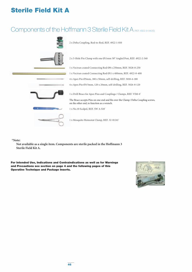
Sterile Field Kit A
2 x Delta Coupling, Rod-to-Rod, REF. 4922-1-010
2 x 5-Hole Pin Clamp with one Ø11mm 30° Angled Post, REF. 4922-2-340
1 x Vectran coated Connecting Rod Ø8 x 250mm, REF. 5028-8-250
1 x Vectran coated Connecting Rod Ø11 x 400mm, REF. 4922-8-400
4 x Apex Pin Ø5mm, 180 x 50mm, self-drilling, REF. 5018-6-180
4 x Apex Pin Ø3/5mm, 120 x 20mm, self-drilling, REF. 5026-8-120
1 x Drill Brace for Apex Pins and Couplings / Clamps, REF. VIM-0*
The Brace accepts Pins on one end and fits over the Clamp / Delta Coupling screws, on the other end, to function as a wrench.
1 x No.10 Scalpel, REF. SW A-S10*
1 x Mosquito Hemostat Clamp, REF. 32-01241*
Components of the Hoffmann 3 Sterile Field Kit A (REF. 4922-9-940S):
* Note: Not available as a single item. Components are sterile packed in the Hoffmann 3
Sterile Field Kit A.
For Intended Use, Indications and Contraindications as well as for Warnings and Precautions see section on page 4 and the following pages of this Operative Technique and Package Inserts.
47
Sterile Field Kit A
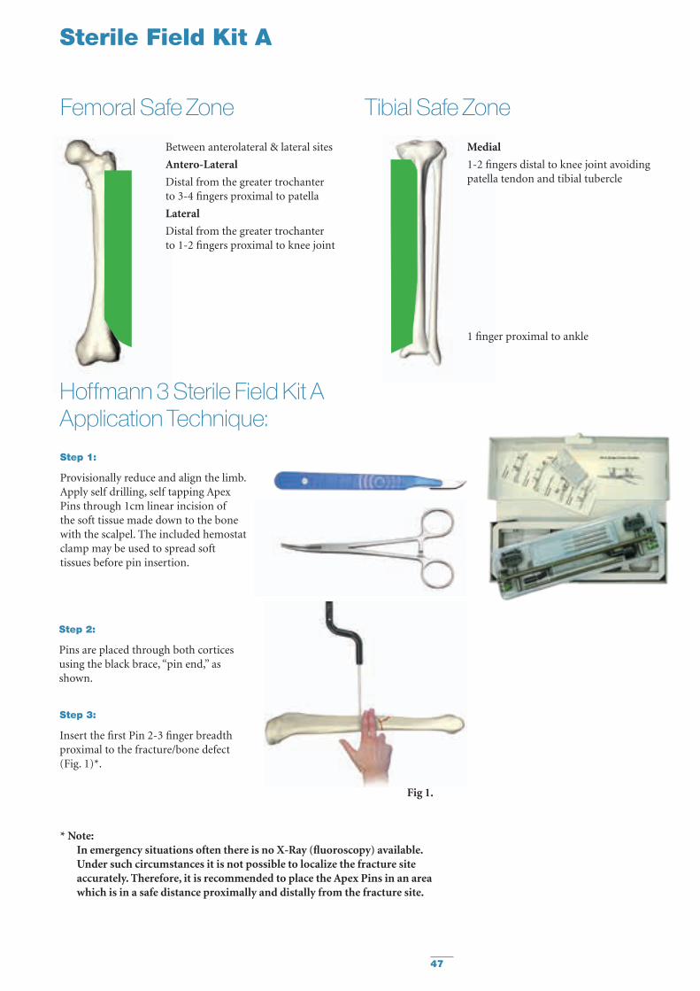
Step 1:
Provisionally reduce and align the limb. Apply self drilling, self tapping Apex Pins through 1cm linear incision of the soft tissue made down to the bone with the scalpel. The included hemostat clamp may be used to spread soft tissues before pin insertion.
Fig 1.
Step 2:
Pins are placed through both cortices using the black brace, “pin end,” as shown.
Between anterolateral & lateral sites
Antero-Lateral
Distal from the greater trochanter to 3-4 fingers proximal to patella
Lateral
Distal from the greater trochanter to 1-2 fingers proximal to knee joint
Femoral Safe Zone Tibial Safe ZoneMedial
1-2 fingers distal to knee joint avoiding patella tendon and tibial tubercle
1 finger proximal to ankle
Hoffmann 3 Sterile Field Kit A Application Technique:
Step 3:
Insert the first Pin 2-3 finger breadth proximal to the fracture/bone defect (Fig. 1)*.
* Note: In emergency situations often there is no X-Ray (fluoroscopy) available.
Under such circumstances it is not possible to localize the fracture site accurately. Therefore, it is recommended to place the Apex Pins in an area which is in a safe distance proximally and distally from the fracture site.
48
Sterile Field Kit A
Fig 5.
Fig 3.
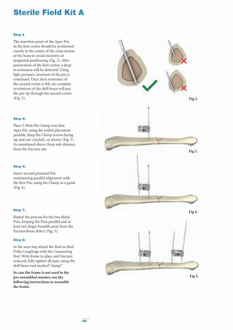
Step 5:
Place 5-Hole Pin Clamp over first Apex Pin, using the widest placement possible. Keep the Clamp Screws facing up and out (medial), as shown (Fig. 3). As mentioned above: Keep safe distance from the fracture site.
Step 6:
Insert second proximal Pin maintaining parallel alignment with the first Pin, using the Clamp as a guide (Fig. 4).
Step 7:
Repeat the process for the two distal Pins, keeping the Pins parallel and at least two finger breadth away from the fracture/bone defect (Fig. 5).
Step 8:
In the next step attach the Rod-to-Rod Delta Couplings with the Connecting Rod. With frame in place and fracture reduced, fully tighten all nuts, using the drill brace end marked “clamp”.
In case the frame is not used in the pre-assembled manner, use the following instructions to assemble the frame.
Fig 4.
Fig 2.
Step 4
The insertion point of the Apex Pin in the first cortex should be positioned exactly in the center of the cross-section of the bone to avoid excentric or tangential positioning (Fig. 2). After penetration of the first cortex, a drop in resistance will be detected. Using light pressure, insertion of the pin is continued. Once firm resistance of the second cortex is felt, six complete revolutions of the drill brace will put the pin tip through the second cortex (Fig. 2).

49
Sterile Field Kit A
Step 9:
Attach the Delta Rod-to-Rod Couplings as shown. Use care to avoid the 30° bend area when tightening the Couplings onto the Posts (Fig. 6).
Step 10:
Snap a Connecting Rod to the Coupling. Provisionally tighten using the thumbwheel (Fig. 7).
Step 11:
Remove the thumbwheel from the Rod-to-Rod Coupling to prepare for final tightening (Fig. 8).
Fig 8.
Fig 6.
Fig 7.
Step 12:
Use the “Clamp” end of the Brace for final tightening while maintaining reduction and alignment of the limb. Repeat for all Clamps and Couplings (Fig. 9).
Fig 9.

50
Sterile Field Kit A
Knee Bridge Frame Example(with Ø11mm Connecting Rod, Ø5mm Apex Pins)
Wrist Bridge Frame Example(with Ø8mm Connecting Rod, Ø3/5mm Apex Pins)
Tibial Frame Example(with Ø11mm Connecting Rod, Ø5mm Apex Pins)
Femoral Frame Example(with Ø11mm Connecting Rod, Ø5mm Apex Pins)
51
Sterile Field Kit B
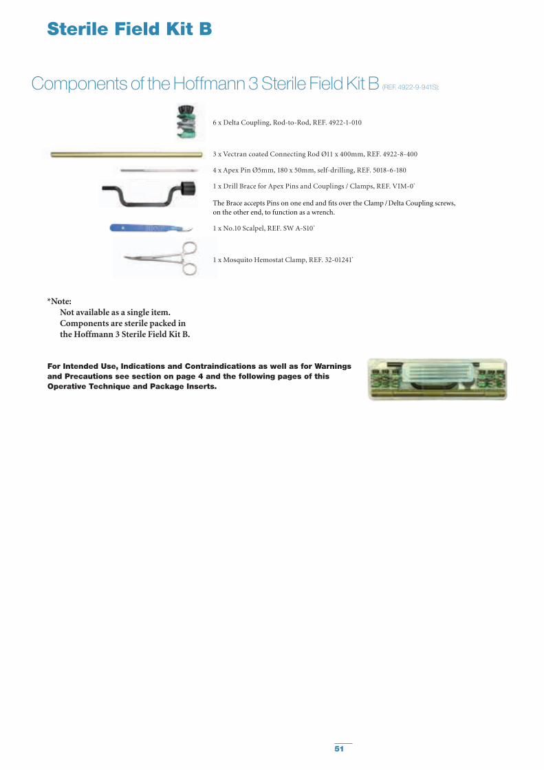
Components of the Hoffmann 3 Sterile Field Kit B (REF. 4922-9-941S):
6 x Delta Coupling, Rod-to-Rod, REF. 4922-1-010
3 x Vectran coated Connecting Rod Ø11 x 400mm, REF. 4922-8-400
4 x Apex Pin Ø5mm, 180 x 50mm, self-drilling, REF. 5018-6-180
1 x Drill Brace for Apex Pins and Couplings / Clamps, REF. VIM-0*
The Brace accepts Pins on one end and fits over the Clamp / Delta Coupling screws, on the other end, to function as a wrench.
1 x No.10 Scalpel, REF. SW A-S10*
1 x Mosquito Hemostat Clamp, REF. 32-01241*
* Note: Not available as a single item.
Components are sterile packed in the Hoffmann 3 Sterile Field Kit B.
For Intended Use, Indications and Contraindications as well as for Warnings and Precautions see section on page 4 and the following pages of this Operative Technique and Package Inserts.
52
Sterile Field Kit B
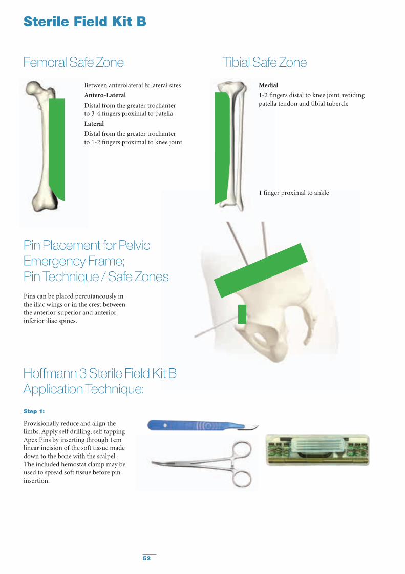
Between anterolateral & lateral sites
Antero-Lateral
Distal from the greater trochanter to 3-4 fingers proximal to patella
Lateral
Distal from the greater trochanter to 1-2 fingers proximal to knee joint
Femoral Safe Zone Tibial Safe ZoneMedial
1-2 fingers distal to knee joint avoiding patella tendon and tibial tubercle
1 finger proximal to ankle
Pin Placement for Pelvic Emergency Frame; Pin Technique / Safe ZonesPins can be placed percutaneously in the iliac wings or in the crest between the anterior-superior and anterior-inferior iliac spines.
Step 1:
Provisionally reduce and align the limbs. Apply self drilling, self tapping Apex Pins by inserting through 1cm linear incision of the soft tissue made down to the bone with the scalpel. The included hemostat clamp may be used to spread soft tissue before pin insertion.
Hoffmann 3 Sterile Field Kit B Application Technique:

53
Tibial Safe Zone
Fig 1.
“Pin end”Step 2:
Pins are placed through both cortices using the black brace, “Pin end,” as shown.
Step 3:
Insert the first Pin 2-3 finger breadth away from the fracture / bone defect (Fig 1)*.
Step 4:
The insertion point of the Apex Pin in the first cortex should be positioned exactly in the center of the cross-section of the bone to avoid excentric or tangential positioning (Fig. 2). After penetration of the first cortex, a drop in resistance will be detected. Using light pressure, insertion of the pin is continued. Once firm resistance of the second cortex is felt, six complete revolutions of the drill brace will put the pin tip through the second cortex (Fig 2).
Sterile Field Kit B
Fig 3.
Step 5:
Place second Pin in the same limb/fragment. (Fig 3).
Note: The larger the distance between
these two pins the more stable the construct will be**
Fig 4.
Step 6:
Attach one Delta Coupling to each Pin***.
Fig 2.
** Gernot Asche, Wolfgang Roth, Ludwig Schroeder (eds.): The External Fixator - Standard indications, operating instructions and examples of frame configurations; Markus Behrens: The mechanics and stability of fixator components. Page 32 ff.
*** For increased stability follow the «rule of thumb»: «In» – «Up», meaning the Delta Couplings shall be «in» between the pins, the black Thumbwheels looking «up» so that one has access to them for easy tightening.
* Note: In emergency situations often there is no X-Ray (fluoroscopy) available. Under such circumstances it is not possible to localize the fracture site accurately. Therefore, it is recommended to place the Apex Pins in an area which is in a safe distance from the fracture site.
54
Sterile Field Kit B
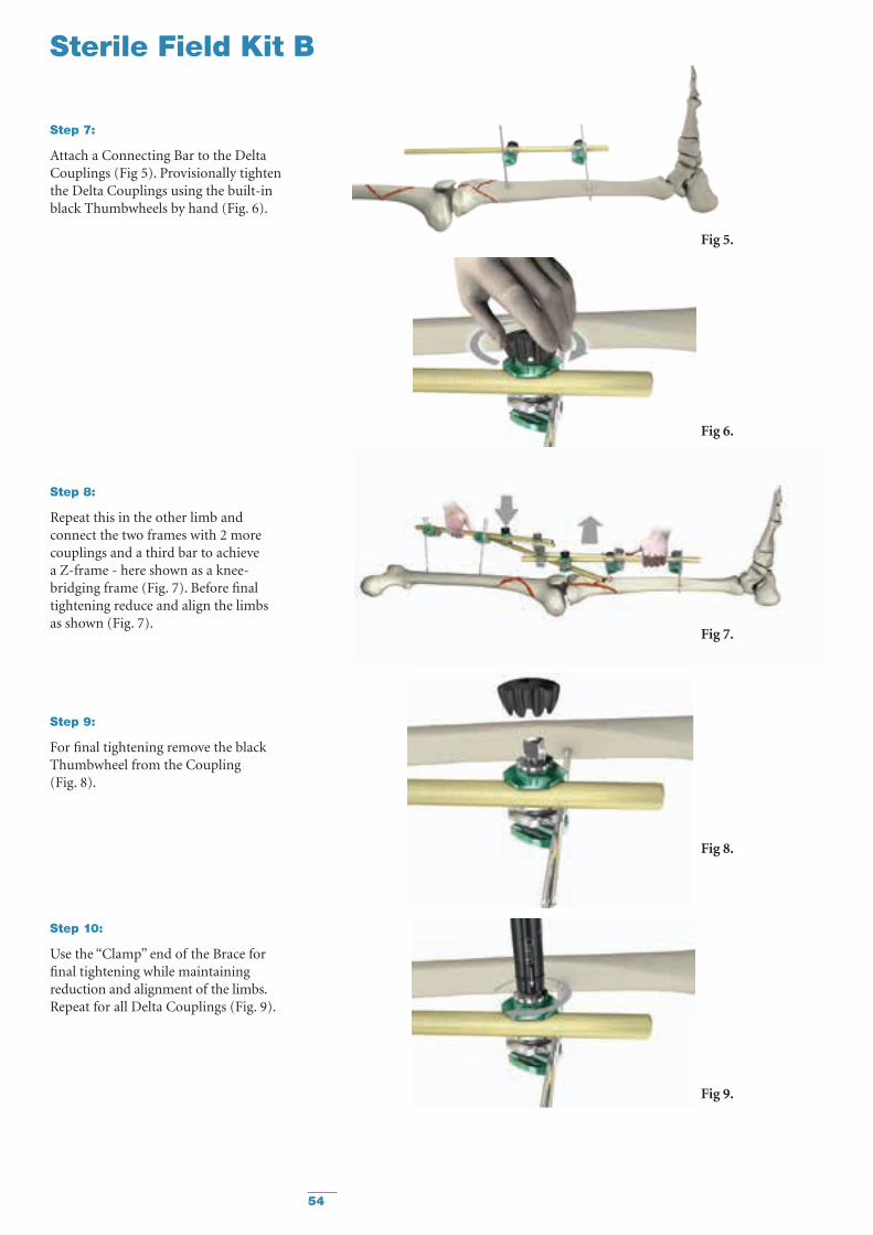
Step 9:
For final tightening remove the black Thumbwheel from the Coupling (Fig. 8).
Step 10:
Use the “Clamp” end of the Brace for final tightening while maintaining reduction and alignment of the limbs. Repeat for all Delta Couplings (Fig. 9).
Fig 6.
Step 7:
Attach a Connecting Bar to the Delta Couplings (Fig 5). Provisionally tighten the Delta Couplings using the built-in black Thumbwheels by hand (Fig. 6).
Step 8:
Repeat this in the other limb and connect the two frames with 2 more couplings and a third bar to achieve a Z-frame - here shown as a knee-bridging frame (Fig. 7). Before final tightening reduce and align the limbs as shown (Fig. 7).
Fig 7.
Fig 8.
Fig 9.
Fig 5.
55
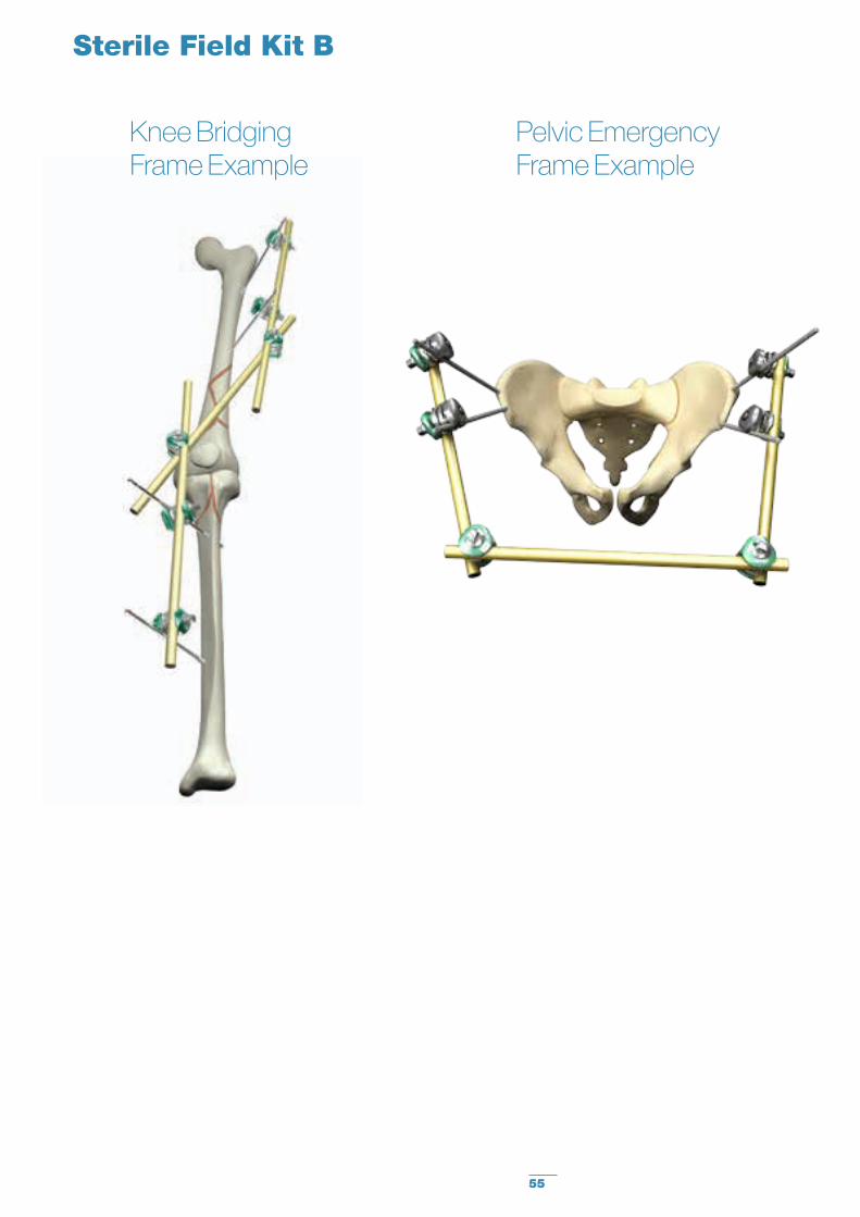
Sterile Field Kit B
Knee Bridging Frame Example
Pelvic Emergency Frame Example

56
Notes

57
Notes

Manufactured by:
Stryker Trauma AGBohnackerweg 1CH - 2545 SelzachSwitzerland
www.osteosynthesis.stryker.com
This document is intended solely for the use of healthcare professionals. A surgeon must always rely on his or her own professional clinical judgment when deciding whether to use a particular product when treating a particular patient. Stryker does not dispense medical advice and recommends that surgeons be trained in the use of any particular product before using it in surgery.
The information presented is intended to demonstrate a Stryker product. A surgeon must always refer to the package insert, product label and/or instructions for use, including the instructions for Cleaning and Sterilization (if applicable), before using any Stryker product. Products may not be available in all markets because product availability is subject to the regulatory and/or medical practices in individual markets. Please contact your Stryker representative if you have questions about the availability of Stryker products in your area.
Stryker Corporation or its divisions or other corporate affiliated entities own, use or have applied for the following trademarks or service marks: Apex, Hoffmann, Stryker. All other trademarks are trademarks of their respective owners or holders.
The products listed above are CE marked.
Literature Number : 982366 Rev 2
Copyright © 2012 Stryker