HOFFMAN FILTRATION SYSTEMS - Air Liquid...
12
HOFFMAN FILTRATION SYSTEMS MANUFACTURED BY Vacu-Matic fi Liquid Filtration Systems
Transcript of HOFFMAN FILTRATION SYSTEMS - Air Liquid...

HOFFMAN FILTRATION SYSTEMS
MANUFACTURED BY
Vacu-Matic® Liquid Filtration Systems
HOFFMAN Filtration Leadership And Manufacturing Excellence
AIR LIQUID SYSTEMS, INC. Air Liquid Systems, Inc. is an industrial manufacturing and service company serving worldwide customers for over 25 years. We specialize in the design and manu-facture of the Hoffman line of Liquid Filtration Sys-tems, design and manufacture of complete strip drying systems, and the supply of all filter and strip dryer spare parts and accessories.
Air Liquid Systems, Inc. and its representative network offer total solutions to filtration needs. Representatives provide on-site discussions and plant surveys to ensure complete satisfaction with product placement, and full understanding of the customer�s application. Sales per-sonnel are experienced engineers with the ability to package a complete systems to meet the customer�s requirements.
Filtration Effectiveness In A Wide Variety Of Coolant And Processing Applications
• Phosphatizing • Paint Booth Filtration • Clarifier Underflow • Can Body Production • Food Waste • Wet Scrubbers • Parts Washing
1 • Grinding Applications • Hot & Cold Rolling • Wire Drawing • Machining Coolants • Caustic Washes • Continuous Casting • Mill Waste Filtration
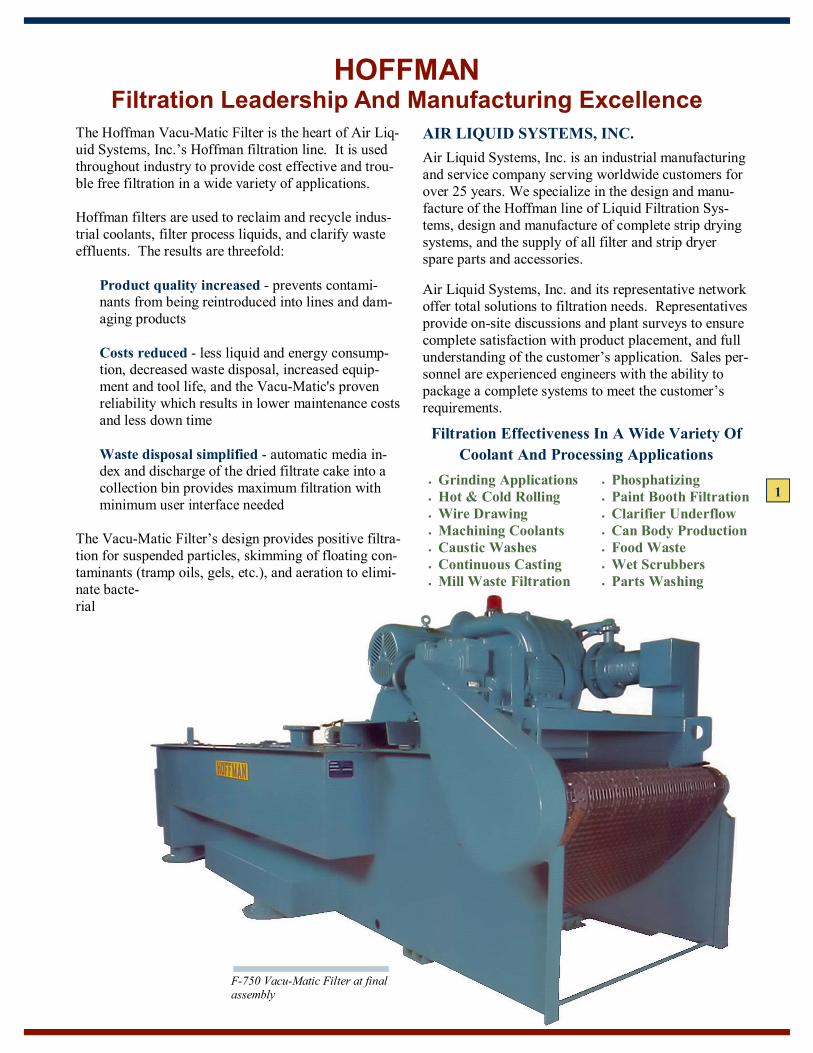
The Hoffman Vacu-Matic Filter is the heart of Air Liq-uid Systems, Inc.�s Hoffman filtration line. It is used throughout industry to provide cost effective and trou-ble free filtration in a wide variety of applications. Hoffman filters are used to reclaim and recycle indus-trial coolants, filter process liquids, and clarify waste effluents. The results are threefold:
Product quality increased - prevents contami-nants from being reintroduced into lines and dam-aging products Costs reduced - less liquid and energy consump-tion, decreased waste disposal, increased equip-ment and tool life, and the Vacu-Matic's proven reliability which results in lower maintenance costs and less down time
Waste disposal simplified - automatic media in-dex and discharge of the dried filtrate cake into a collection bin provides maximum filtration with minimum user interface needed
The Vacu-Matic Filter�s design provides positive filtra-tion for suspended particles, skimming of floating con-taminants (tramp oils, gels, etc.), and aeration to elimi-nate bacte-rial
F-750 Vacu-Matic Filter at final assembly

AN OVERVIEW OF THE VACU-MATIC'S® . . . Filtration Process Hoffman Vacu-Matic Filters are flat bed vacuum units. A continuous metal conveyor belt supports the dispos-able filter media, while a heavy-duty Gardner Denver exhauster creates a vacuum beneath the media. As the liquid to be filtered is drawn through, a filter cake is formed. As the cake thickens, the vacuum increases and, at a preset limit, a vacuum switch causes the belt (and media) to be indexed. As media is newly exposed, it can be pre-coated by dirty liquid prior to entering the vacuum chamber. . . . Benefits The Vacu-Matic utilizes the flow of air to perform three major functions. First, air is used to dry the cake prior to sludge removal. This minimizes loss of process liquids and reduces sludge disposal costs. Second, us-ing the standard air skimmer, air flow is directed by the exhauster discharge over the liquid pool to skim away floating contaminants. Third, air passing the filter chamber aerates the cleaned liquid. This is particularly important in the case of coolants to control bacteria growth and resulting coolant rancidity.
2
VACU-MATIC® FILTER
F-750 shown at a customer�s plant filtering contaminated water from a mill hotwell
. . . Standard Components Exhauster - Heavy duty Gardner Denver's Hoffman cast iron exhausters are installed on all Vacu-Matic filters. All heads and sections of this unit are con-structed of cast iron, which reduces sound levels, en-sures longevity, and simplifies maintenance. Cast iron construction also permits Gardner Denver to design flow passages which maximize efficiency. Adjacent to the blower is the drive and motor gearbox used to index the media belt.
Seal and Flat Wire Belt - Hoffman's unique seal and flat wire belt are built-in to each Vacu-Matic unit. Per-manent butterfly clips form the moving seal in the car-bon steel flat wire belt (other materials optional). The stationary component of the seal is a PVC extrusion (Buna "N" and Teflon also available) held in place by stainless steel hold down springs. This assembly se-curely holds the media to the belt and ensures a positive liquid seal. Special seal arrangements are used for paint sludges and other "problem" filtrates.
Gardner Denver 4203A eaxhauster and 20 HP motor on Vac-1000 filter
Flat wire conveyor belt with permanent butterfly clips; stationary seal secured with stainless steel hold down springs.

3
A WORKING VIEW
HI-FLO VACU-MATIC® OPERATION The feeder pump supplies the Vacu-Matic with con-taminated process liquid from the dirty tank. This liq-uid is pumped to the distributor, where it is evenly por-tioned across the pool on the filter bed. The bed con-sists of a flat wire belt supporting the filter media itself. A Gardner Denver exhauster produces vacuum in the chamber beneath the filter bed, drawing the liquid through the media and the built-up deposit of solids (filter cake). When the pressure drop across the filter cake/media reaches a given limit, an electrical switch
is closed. This indexes the media and dried filter cake into the disposal container.
At the same time, clean filter media is drawn onto the filter bed. Both the vacuum in the vacuum chamber and the liquid level drop due to the inrush of liquid through the fresh media. This sudden flow builds the filter cake back to a functional level. The clean liquid passing through the filter cake and media drains into the clean liquid compartment of the holding tank. A "water leg" is maintained in the clean overflow pipe to sustain a vacuum in the filter. Where excessive floating solids or tramp oil exist in the incoming process liquid, discharge air from the vacuum producer can is used to operate the standard air skim-mer. This moves any loose floating materials toward the dirty end of the filter for removal as media is in-dexed. Should the filter bed become flooded due to mechanical malfunction or unexpected impurities in the process, the liquid level is reduced via the overflow slot con-nected to the side gutter. This is connected to an over-flow drain pipe dumping into the dirty compartment of the holding tank.
Vacuum Switch
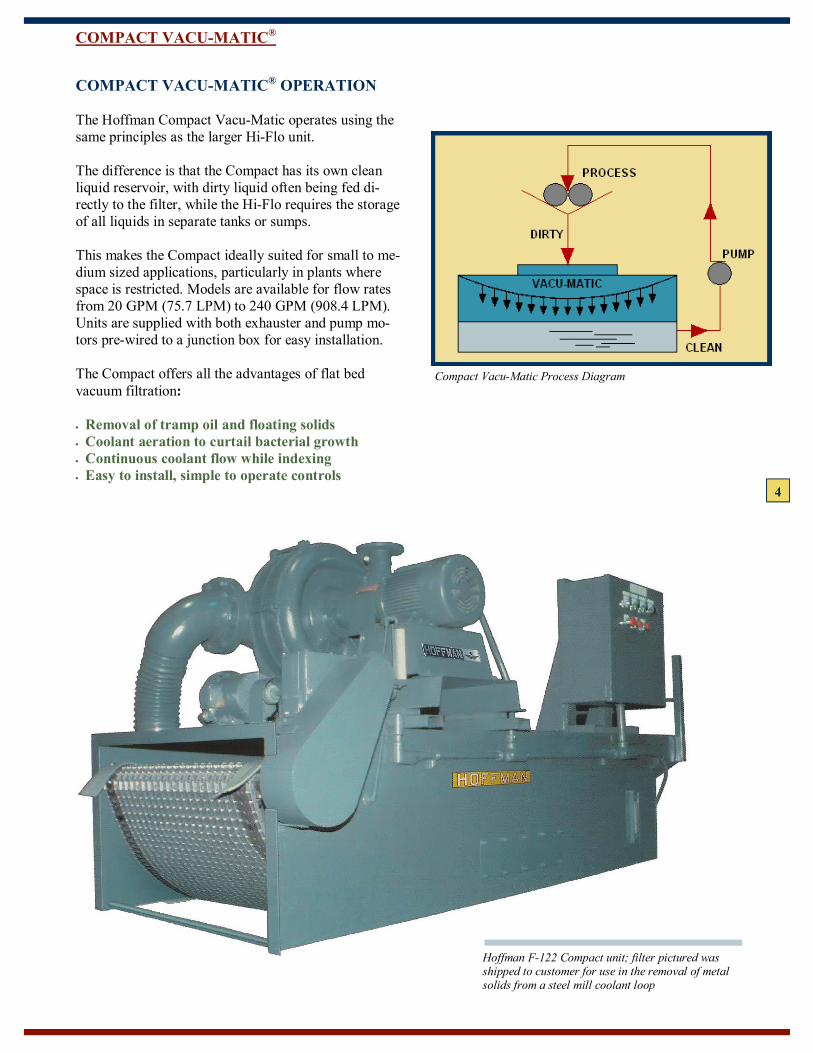
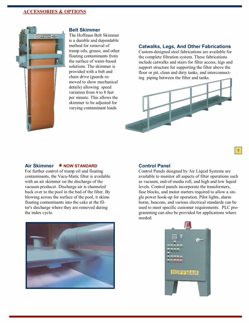
COMPACT VACU-MATIC® OPERATION The Hoffman Compact Vacu-Matic operates using the same principles as the larger Hi-Flo unit. The difference is that the Compact has its own clean liquid reservoir, with dirty liquid often being fed di-rectly to the filter, while the Hi-Flo requires the storage of all liquids in separate tanks or sumps. This makes the Compact ideally suited for small to me-dium sized applications, particularly in plants where space is restricted. Models are available for flow rates from 20 GPM (75.7 LPM) to 240 GPM (908.4 LPM). Units are supplied with both exhauster and pump mo-tors pre-wired to a junction box for easy installation. The Compact offers all the advantages of flat bed vacuum filtration: • Removal of tramp oil and floating solids • Coolant aeration to curtail bacterial growth • Continuous coolant flow while indexing • Easy to install, simple to operate controls
COMPACT VACU-MATIC®
Compact Vacu-Matic Process Diagram
Hoffman F-122 Compact unit; filter pictured was shipped to customer for use in the removal of metal solids from a steel mill coolant loop
4

PROCESS DIAGRAMS
Gravity flow to Hoffman Sludge Collecting Tank (primary clarifier); pump to filter
Gravity flow to filter; pump back to process. Storage tanks supplied with filter
5
Cone bottom dirty reservoir below floor. Filter and clean tank above floor Gravity flow to filter; pump back to process. Sumps/ tanks in plant
Model F-2500 Vacu-Matic Filter assembled with clean/dirty tank below the filter, and catwalk structure to enable ready access to the filter�s mechanical com-ponents.
Total System Capabilities To Meet Filtration Needs Air Liquid Systems, Inc. offers a wide variety of Hoff-man Vacu-Matic products, options and accessories to completely handle your plant�s filtration needs. Our personnel also have a broad knowledge of related process-liquid equipment for integration into complete systems. We have the experience to engineer and project manage total systems, or to supply basic components for easy installation by the customer. Whatever your needs, our experienced representative network will help you capi-talize on your plant�s filtration opportunities, and assist your company to: • Increased equipment and tool life • Reduced maintenance costs • Higher product quality • Lower liquid consumption • Increased reclamation value • Enhanced labor productivity • Decreased energy and waste disposal costs • Greater equipment output

DESIGN & CONSTRUCTION
General layout of standard Vac-2500 filter with exhauster assembly
Each filter and system are designed in the latest ver-sion of AutoCAD. A project engineer oversees each filter and system from proposal through fabrication and assembly, providing status updates at project milestones as requested by the customer. Experienced welding technicians fabricate the filter tanks in standard carbon steel or stainless steel , de-pending upon the environment in which the unit will be working. Flat wire belts and other components can also be supplied in carbon steel or stainless steel. Components are assembled to the unit prior to ship-ment, including the Gardner Denver exhauster and motor, index motor, switches, and gauges. The filter media is shipped loose to prevent damage, with instructions for the customer to install on-site.
Fabrication of standard Vacu-Matic F1000 filter tank for use on aluminum rolling mill
6
7
ACCESSORIES & OPTIONS
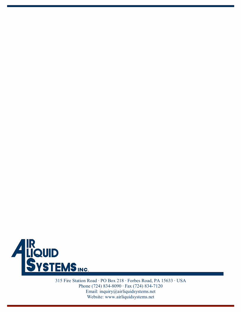
Catwalks, Legs, And Other Fabrications Custom-designed steel fabrications are available for the complete filtration system. These fabrications include catwalks and stairs for filter access, legs and support structure for supporting the filter above the floor or pit, clean and dirty tanks, and interconnect-ing piping between the filter and tanks.
Belt Skimmer The Hoffman Belt Skimmer is a durable and dependable method for removal of tramp oils, grease, and other floating contaminants from the surface of water-based solutions. The skimmer is provided with a belt and chain drive (guards re-moved to show mechanical details) allowing speed variation from 4 to 8 feet per minute. This allows the skimmer to be adjusted for varying contaminant loads.
Air Skimmer NOW STANDARD For further control of tramp oil and floating contaminants, the Vacu-Matic filter is available with an air skimmer on the discharge of the vacuum producer. Discharge air is channeled back over to the pool in the bed of the filter. By blowing across the surface of the pool, it skims floating contaminants into the cake at the fil-ter's discharge where they are removed during the index cycle.
Control Panel Control Panels designed by Air Liquid Systems are available to monitor all aspects of filter operations such as vacuum, end-of-media roll, and high and low liquid levels. Control panels incorporate the transformers, fuse blocks, and motor starters required to allow a sin-gle power hook-up for operation. Pilot lights, alarm horns, beacons, and various electrical standards can be used to meet specific customer requirements. PLC pro-gramming can also be provided for applications where needed.

8
In addition to the Vacu-Matic Filters described in the preceding passages, Air Liquid Systems offers a number of related Hoffman filtration and distillation equipment product lines. Each of these is designed to permit the most economical and maintenance-free reuse of process liquids.
Sludge Collection Tanks Hoffman Sludge Collection tanks are available in both standard and custom sizes and configurations. Appli-cations are most frequently found in industries where machining and grinding produce large quantities of high specific gravity waste products.
Disk And Cartridge Filters These units are compact in size and used in low flow applications (1-125 GPM/ 3.8 473.1 LPM). Housings can be fitted with either disk or replace-able cartridge filter elements.
ADDITIONAL FILTRATION & CLARIFICATION PRODUCTS
Magnaflo Magnetic Separators As with several other Hoffman filtration products, Magnaflo units are used most often in machining industries. Magnetic solids from machining and grinding are easily removed by the Magnaflo's strong ceramic magnets. The Magnaflo is available in 13 sizes with storage capacities ranging from 160 to 6,600 gallons (606 to 24,980 liters). Flow rates can be as great as 1,000 GPM (3,875 LPM).
Vacuum Stills Hoffman Vacuum Stills are steam heated, pot-type units designed to separate high boiling tem-perature solvents from oils and greases. Distilled
solvents are auto-matically removed and pumped to clean storage. Likewise, collected wastes are pumped out without shut-down of the distil-lation unit. Avail-able in five sizes with nominal ca-pacities of 40 to 600 gallons per hour (150 to 2,270 liters per hour), these units are de-signed for continu-ous operation and minimum mainte-nance.

9
F200 F300 F400 F500 F750 F1000 F1500 F2000 F2500 F3000 F3500 F4000 F4500
FILTER AREA, Sq. Feet 17 23 26 29 35 45 55 72 89 110 129 147 165
Filter Area, Sq. Meters 1.58 2.14 2.4 2.7 3.3 4.2 5.1 6.7 8.3 10.2 12 13.7 15.3
Length �A�, Feet/ Inches 12�-5� 15�-2� 16�-1� 17�-4� 19�-7� 20�-8� 23�-8� 27�-8� 32�-8� 35�-6� 40�-3� 45�-0� 49�-9�
Length �A�, Meters 3.8 4.6 4.9 5.3 6.0 6.3 7.2 8.4 10.0 10.8 12.3 13.7 15.2
Width �B�, Feet/ Inches 4�-0� 4�-0� 5�-2� 5�-2� 5�-2� 6�-2� 6�-4� 6�-4� 6�-7� 7�-4� 7�-4� 7�-6� 7�-6�
Width �B�, Meters 1.2 1.2 1.6 1.6 1.6 1.88 1.93 1.93 2.0 2.24 2.24 2.3 2.3
Height �C�, Feet/ Inches 4�-10� 4�-10� 6�-5� 6�-5� 6�-5� 6�-8� 6�-8� 7�-4� 7�-4� 7�-7� 7�-7� 7�-7� 7�-7�
Height �C�, Meters 1.5 1.5 1.9 1.9 1.9 2.0 2.0 2.23 2.23 2.3 2.3 2.3 2.3
Water Leg �D�, Inches 28� 28� 42� 42� 42� 78� 78� 78� 78� 78� 78� 78� 78�
Water Leg �D�, Meters 0.71 0.71 1.1 1.1 1.1 1.42 1.42 1.42 1.42 1.42 1.42 1.42 1.42
Exhauster Motor, HP 5 5 10 10 10 20 20 20 20 20 20 20 20
Exhauster Motor, KW 3.73 3.73 7.46 7.46 7.46 14.91 14.91 14.91 14.91 14.91 14.91 14.91 14.91
Weight, LBS. 2,800 3,100 4,150 5,585 6,500 9,600 13,000 15,000 16,000 18,000 19,500 21,000 24,000
Weight, KG. 1,270 1,400 1,880 2,530 2,950 4,360 5,900 6,800 7,270 8,180 8,860 9,500 10,900
Hi-Flo Vacu-Matic®
HI-FLO �F� SERIES
SPECIFICATIONS & DIMENSIONS
MAX. LIQUID LEVEL IN CLEAN TANK
W75 W90 W120 W148 W162 W190 W215 W250
FILTER AREA, Sq. Feet 75 90 120 148 162 190 215 250
Filter Area, Sq. Meters 7.0 8.4 11.0 13.7 15.0 17.6 20.0 23.2
Length �A�, Feet/ Inches 21�-9� 24�-9� 28�-9� 33�-9� 36�-1� 40�-10� 45�-7� 50�-4�
Length �A�, Meters 6.6 7.5 8.8 10.3 11.0 12.4 13.9 15.3
Width �B�, Feet/ Inches 8�-10� 8�-10� 9�-0� 9�-0� 9�-4� 9�-4� 9�-4� 9�-4�
Width �B�, Meters 2.69 2.69 2.74 2.74 2.85 2.85 2.85 2.85
Height �C�, Feet/ Inches 6�-11� 6�-11� 7�-6� 7�-6� 7�-8� 7�-8� 7�-8� 7�-8�
Height �C�, Meters 2.1 2.1 2.3 2.3 2.34 2.34 2.34 2.34
Water Leg �D�, Inches 78� 78� 78� 78� 78� 78� 78� 78�
Water Leg �D�, Meters 1.42 1.42 1.42 1.42 1.42 1.42 1.42 1.42
Exhauster Motor, HP 20 20 20 20 20 20 20 20
Exhauster Motor, KW 14.91 14.91 14.91 14.91 14.91 14.91 14.91 14.91
Weight, LBS. 15,000 16,000 19,500 21,000 24,000 27,000 30,000 32,500
Weight, KG. 6,800 7,275 8,865 9,550 10,900 12,300 13,600 14,800
HI-FLO �W� SERIES

10
8W110 8W130 8W160 8W200 8W220 8W255 8W290 8W330
FILTER AREA, Sq. Feet 110 130 160 200 220 255 290 330
Filter Area, Sq. Meters 10.22 12.08 14.86 18.58 20.44 23.69 26.94 30.66
Length �A�, Feet/ Inches 21�-9� 24�-9� 28�-9� 33�-9� 36�-1� 40�-10� 45�-7� 50�-4�
Length �A�, Meters 6.6 7.5 8.8 10.3 11.0 12.4 13.9 15.3
Width �B�, Feet/ Inches 11� 2-1/4� 11� 2-1/4� 11� 2-1/4� 11� 4-1/4� 12� 2-3/4� 12� 2-3/4� 12� 2-3/4� 12� 2-3/4�
Width �B�, Meters 3.41 3.41 3.41 3.46 3.73 3.73 3.73 3.73
Height �C�, Feet/ Inches 6�-11� 6�-11� 7�-6� 7�-6� 7�-8� 7�-8� 7�-8� 7�-8�
Height �C�, Meters 2.1 2.1 2.3 2.3 2.34 2.34 2.34 2.34
Water Leg �D�, Inches 78� 78� 78� 78� 78� 78� 78� 78�
Water Leg �D�, Meters 1.42 1.42 1.42 1.42 1.42 1.42 1.42 1.42
Exhauster Motor, HP 20 20 20 20 20 20 20 20
Exhauster Motor, KW 14.91 14.91 14.91 14.91 14.91 14.91 14.91 14.91
Weight, LBS. 20,000 21,000 26,000 28,000 32,000 36,000 40,000 42,000
Weight, KG. 9,072 9,520 11,793 12,701 14,515 16,330 18,144 19,051
HI-FLO �8W� SERIES
Compact Vacu-Matic®
F40 F60 F80 F120 F122 F124 F126
FILTER AREA, Sq. Feet 4.2 4.2 12 12 16.6 21 26
Filter Area, Sq. Meters 0.4 0.4 1.1 1.1 1.5 1.95 2.4
Length �A�, Feet/ Inches 6�-8� 6�-8� 8�-7� 8�-7� 10�-7� 12�-7� 14�-7�
Length �A�, Meters 2.0 2.0 2.6 2.6 3.2 3.8 4.5
Width �B�, Feet/ Inches 2�-8� 2�-8� 4�-2� 4�-2� 4�-2� 4�-2� 4�-2�
Width �B�, Meters 0.8 0.8 1.3 1.3 1.3 1.3 1.3
Height �C�, Feet/ Inches 2�-11� 2�-11� 4�-4� 4�-4� 4�-4� 4�-4� 4�-4�
Height �C�, Meters 0.9 0.9 1.3 1.3 1.3 1.3 1.3
Height to Distributor Top �D�, Inches 18� 18� 22-1/2� 22-1/2� 22-1/2� 22-1/2� 22-1/2�
Height to Distributor Top �D�, Meters 0.46 0.46 0.572 0.572 0.572 0.572 0.572
Exhauster Motor, HP 1 1-1/2 3 5 5 5 5
Exhauster Motor, KW 0.746 1.12 2.24 3.73 3.73 3.73 3.73
Weight, LBS. 990 1,100 1,160 1,620 1,740 1,860 1,980
Weight, KG. 450 500 527 735 790 845 900
Reservoir Capacity, Liters 190 190 490 490 580 675 765
Reservoir Capacity, US Gal. 50 50 130 130 154 178 202
COMPACT �F� SERIES
315 Fire Station Road · PO Box 218 · Forbes Road, PA 15633 · USA Phone (724) 834-8090 · Fax (724) 834-7120
Email: [email protected] Website: www.airliquidsystems.net