HMT.pdf · DHANALAKSHMI SRINIVASAN COLLEGE OF ENGINEERING AND TECHNOLOGY DEPARTMENT OF MECHANICAL...
163
DHANALAKSHMI SRINIVASAN COLLEGE OF ENGINEERING AND TECHNOLOGY DEPARTMENT OF MECHANICAL ENGINEERING UNIT: I - CONDUCTION PART A - 2 Marks (Questions and Answers) 1. State Fourier’s Law of conduction. (April/May 2011, Nov/Dec 14, Nov/Dec 16) The rate of heat conduction is proportional to the area measured – normal to the direction of heat flow and to the temperature gradient in that direction. Where, A are in m2 is temperature gradient in K/m K is Thermal Conductivity W/mk 2. State Newton’s law of cooling or convection law. (May/June 2009) Heat transfer by convection is given by Newton’s law of cooling Q = hA (Ts - T∞) Where A – Area exposed to heat transfer in m2 , h - heat transfer coefficient in W/m2K Ts – Temperature of the surface in K, T∞ - Temperature of the fluid in K. 3. Define overall heat transfer co-efficient. (May/June 2007) The overall heat transfer by combined modes is usually expressed in terms of an overall conductance or overall heat transfer co-efficient ‘U’. Heat transfer Q = UA ∆T. 4. Write down the equation for heat transfer through composite pipes or cylinder. (April/May 2008) Heat transfer where
Transcript of HMT.pdf · DHANALAKSHMI SRINIVASAN COLLEGE OF ENGINEERING AND TECHNOLOGY DEPARTMENT OF MECHANICAL...

DHANALAKSHMI SRINIVASAN
COLLEGE OF ENGINEERING AND TECHNOLOGY
DEPARTMENT OF MECHANICAL ENGINEERING
UNIT: I - CONDUCTION
PART A - 2 Marks (Questions and Answers)
1. State Fourier’s Law of conduction. (April/May 2011, Nov/Dec 14,
Nov/Dec 16)
The rate of heat conduction is proportional to the area measured – normal to the
direction of heat flow and to the temperature gradient in that direction.
Where, A are in m2
is temperature gradient in K/m
K is Thermal Conductivity W/mk
2. State Newton’s law of cooling or convection law. (May/June 2009)
Heat transfer by convection is given by Newton’s law of cooling
Q = hA (Ts - T∞)
Where
A – Area exposed to heat transfer in m2 , h - heat transfer coefficient in W/m2K
Ts – Temperature of the surface in K, T∞ - Temperature of the fluid in K.
3. Define overall heat transfer co-efficient. (May/June 2007)
The overall heat transfer by combined modes is usually expressed in terms
of an overall conductance or overall heat transfer co-efficient ‘U’.
Heat transfer Q = UA ∆T.
4. Write down the equation for heat transfer through composite pipes or
cylinder. (April/May 2008)
Heat transfer where

DHANALAKSHMI SRINIVASAN
COLLEGE OF ENGINEERING AND TECHNOLOGY
DEPARTMENT OF MECHANICAL ENGINEERING
5. What is critical radius of insulation (or) critical thickness? (May/June
2014) (Nov/Dec 2008)
Critical radius = rc Critical thickness = rc – r1
Addition of insulating material on a surface does not reduce the amount of
heat transfer rate always. In fact under certain circumstances it actually increases
the heat loss up to certain thickness of insulation. The radius of insulation for
which the heat transfer is maximum is called critical radius of insulation, and the
corresponding thickness is called critical thickness.
6. Define Fin efficiency and Fin effectiveness. (Nov/Dec 2015& Nov/Dec
2010)
The efficiency of a fin is defined as the ratio of actual heat transfer by the
fin to the maximum possible heat transferred by the fin.
Fin effectiveness is the ratio of heat transfer with fin to that without fin
7. Define critical thickness of insulation with its significance. [MAY-JUN 14]
Addition of insulating material on a surface does not reduce the amount of
heat transfer rate always. In fact under certain circumstances it actually increases
the heat loss up to certain thickness of insulation. The radius of insulation for
which the heat transfer is maximum is called critical radius of insulation, and the
corresponding thickness is called critical thickness. For cylinder, Critical radius =
rc = k/h, Where k- Thermal conductivity of insulating material, h- heat transfer
coefficient of surrounding fluid. Significance: electric wire insulation may be
smaller than critical radius. Therefore the plastic insulation may actually enhance
the heat transfer from wires and thus keep their steady operating temperature at
safer levels.
10

DHANALAKSHMI SRINIVASAN
COLLEGE OF ENGINEERING AND TECHNOLOGY
DEPARTMENT OF MECHANICAL ENGINEERING
8. What is lumped system analysis? When is it applicable? [Nov/Dec 14 &
April/May 2010]
In heat transfer analysis, some bodies are observed to behave like a "lump"
whose entire body temperature remains essentially uniform at all times during a
heat transfer process. The temperature of such bodies can be taken to be a
function of time only. Heat transfer analysis which utilizes this idealization is
known as the lumped system analysis. It is applicable when the Biot number (the
ratio of conduction resistance within the body to convection resistance at the
surface of the body) is less than or equal to 0.1.
9. Write the three dimensional heat transfer poisson and laplace equation
in Cartesian co-ordinates(May/June 2012)(April/May 2010)
Poisson equation:
Laplace equation:
10. A 3 mm wire of thermal conductivity 19 W/mK at a steady heat
generation of 500 MW/m3 .Determine the center temperature if the outside
temperature is maintained at 250C ( May 2012)
Critical temperature
11. List down the three types of boundary conditions. (Nov/Dec 2005)
1. Prescribed temperature
2. Prescribed heat flux
3. Convection Boundary Conditions.
11

DHANALAKSHMI SRINIVASAN
COLLEGE OF ENGINEERING AND TECHNOLOGY
DEPARTMENT OF MECHANICAL ENGINEERING
12. Define fins (or) extended surfaces.
It is possible to increase the heat transfer rate by increasing the surface of
heat transfer. The surfaces used for increasing heat transfer are called extended
surfaces or sometimes known as fins.
13. How thermodynamics differ from heat transfer?
Thermodynamics doesn’t deals with rate of heat transfer
Thermodynamics doesn’t tell how long it will occur
Thermodynamics doesn’t tell about the method of heat transfer
PART B - 13 Marks (Questions and Answers)
1. Derive the General Differential Equation of Heat Conduction
in Cartesian coordianates.(NOV/DEC 2014)
Fig 2.1
Consider a small volume element in Cartesian coordinates having sides dx, dy
and dz as shown in Fig. 2.1 the energy balance for this little element is obtained
from the first law of thermodynamics as:
12
DHANALAKSHMI SRINIVASAN
COLLEGE OF ENGINEERING AND TECHNOLOGY
DEPARTMENT OF MECHANICAL ENGINEERING
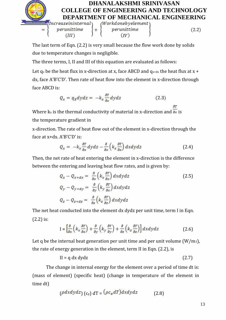
The last term of Eqn. (2.2) is very small because the flow work done by solids
due to temperature changes is negligible.
The three terms, I, II and III of this equation are evaluated as follows:
Let qx be the heat flux in x-direction at x, face ABCD and qx+dx the heat flux at x +
dx, face A’B’C’D’. Then rate of heat flow into the element in x-direction through
face ABCD is:
Where kx is the thermal conductivity of material in x-direction and is
the temperature gradient in
x-direction. The rate of heat flow out of the element in x-direction through the
face at x+dx. A’B’C’D’ is:
(2.4)
Then, the net rate of heat entering the element in x-direction is the difference
between the entering and leaving heat flow rates, and is given by:
(2.5)
The net heat conducted into the element dx dydz per unit time, term I in Eqn.
(2.2) is:
I = (2.6)
Let q be the internal heat generation per unit time and per unit volume (W/m3),
the rate of energy generation in the element, term II in Eqn. (2.2), is
II = q dx dydz (2.7)
The change in internal energy for the element over a period of time dt is:
(mass of element) (specific heat) (change in temperature of the element in
time dt)
( ) (cp) dT = (2.8)
13

DHANALAKSHMI SRINIVASAN
COLLEGE OF ENGINEERING AND TECHNOLOGY
DEPARTMENT OF MECHANICAL ENGINEERING
Where and are the density and specific heat of the material of the element.
Then, the change in internal energy per unit time, term III of Eqn. (2.2) is:
(2.9) Substitution of Eqns.
(2.6),(2.7) and (2.9) into Eqn. (2.2) leads to the general three-dimensional
equation for heat conduction:
(2.10)
Since for most engineering problems the materials can be considered
isotropic for which Kx = Ky = Kz =k= Constant, the general three-dimensional
heat conduction equation becomes:
The quantity is known as the thermal diffusivity, α of the material. It has
got the units m2/s.
2. Derive the Heat conduction equation in cylindrical coordinates.
The heat conduction equation derived in the previous section can be
used for solids with rectangular boundaries like slabs, cubes, etc. but then there
are bodies like cylinders, tubes, cones, spheres to which Cartesian coordinates
system is not applicable.
Fig 2.2
A more suitable system will be one in which the coordinate surfaces coincide
with the boundary surfaces of the region. For cylindrical bodies, a cylindrical
14
DHANALAKSHMI SRINIVASAN
COLLEGE OF ENGINEERING AND TECHNOLOGY
DEPARTMENT OF MECHANICAL ENGINEERING
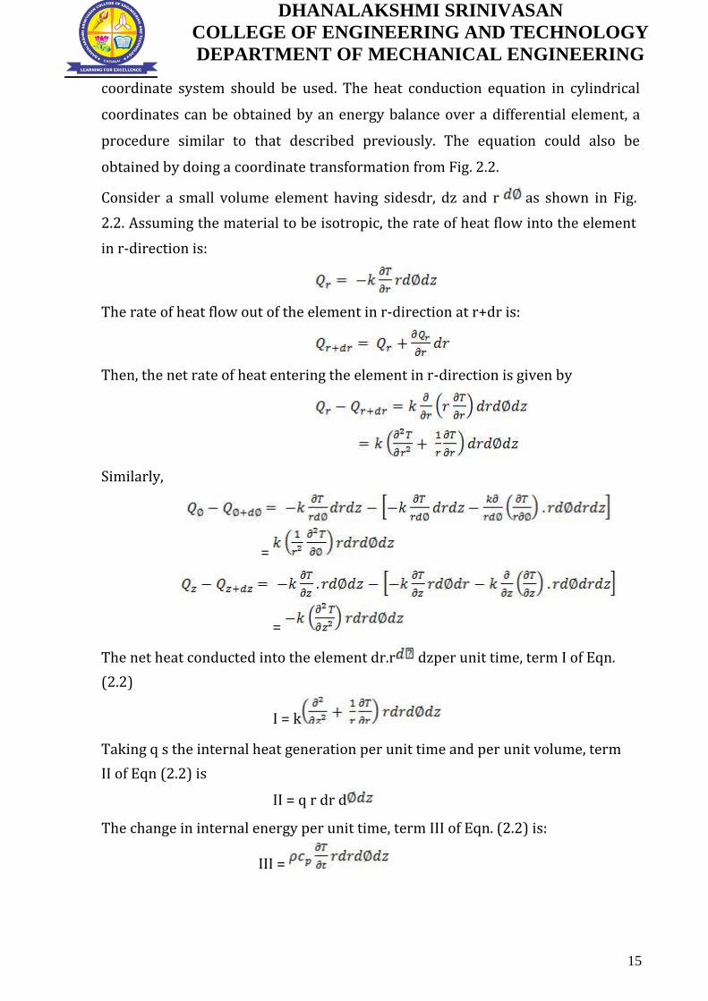
coordinate system should be used. The heat conduction equation in cylindrical
coordinates can be obtained by an energy balance over a differential element, a
procedure similar to that described previously. The equation could also be
obtained by doing a coordinate transformation from Fig. 2.2.
Consider a small volume element having sidesdr, dz and r as shown in Fig.
2.2. Assuming the material to be isotropic, the rate of heat flow into the element
in r-direction is:
The rate of heat flow out of the element in r-direction at r+dr is:
Then, the net rate of heat entering the element in r-direction is given by
Similarly,
=
=
The net heat conducted into the element dr.r dzper unit time, term I of Eqn.
(2.2)
I = k
Taking q s the internal heat generation per unit time and per unit volume, term
II of Eqn (2.2) is
II = q r dr d
The change in internal energy per unit time, term III of Eqn. (2.2) is:
III =
15
DHANALAKSHMI SRINIVASAN
COLLEGE OF ENGINEERING AND TECHNOLOGY
DEPARTMENT OF MECHANICAL ENGINEERING
Substitution of terms I, II and III into the energy balance Eqn. (2.2) leads to three-
dimensional equation for an isentropic material in cylindrical coordinate system
as
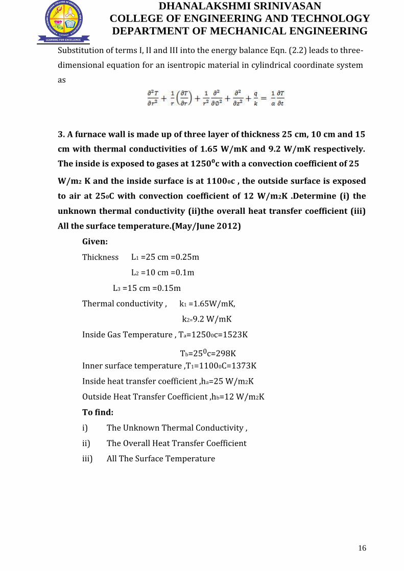
3. A furnace wall is made up of three layer of thickness 25 cm, 10 cm and 15
cm with thermal conductivities of 1.65 W/mK and 9.2 W/mK respectively.
The inside is exposed to gases at 1250⁰c with a convection coefficient of 25
W/m2 K and the inside surface is at 11000c , the outside surface is exposed
to air at 250C with convection coefficient of 12 W/m2K .Determine (i) the
unknown thermal conductivity (ii)the overall heat transfer coefficient (iii)
All the surface temperature.(May/June 2012)
Given:
Thickness
L1 =25 cm =0.25m
L2 =10 cm =0.1m
L3 =15 cm =0.15m
Thermal conductivity , k1 =1.65W/mK,
k2=9.2 W/mK
Inside Gas Temperature , Ta=12500c=1523K
Tb=250c=298K
Inner surface temperature ,T1=11000C=1373K
Inside heat transfer coefficient ,ha=25 W/m2K
Outside Heat Transfer Coefficient ,hb=12 W/m2K
To find:
i) The Unknown Thermal Conductivity ,
ii) The Overall Heat Transfer Coefficient
iii) All The Surface Temperature
16

DHANALAKSHMI SRINIVASAN
COLLEGE OF ENGINEERING AND TECHNOLOGY
DEPARTMENT OF MECHANICAL ENGINEERING
Solution:
STEP-1
Heat transfer =25(1523-
1373)=3750 W/m2
From HMT data book P.No 45
Heat Flow , Q=∆T overall/R
k2=2.816W/mk
STEP-2
From HMT data book P.No 45
Overall Thermal resistance (R)
[Take A=1 m2]
Rtotal=0.3267 W/m2
U=1/Rtotal=1/0.3267=3.06W/m2K
17

DHANALAKSHMI SRINIVASAN
COLLEGE OF ENGINEERING AND TECHNOLOGY
DEPARTMENT OF MECHANICAL ENGINEERING
STEP-3
,
,
T2=804.8K
T3=671.45K
T4=610.30K
4. A furnace wall consists of 200mm layer of refractory bricks, 6 mm layer
of steel plate and a 100mm layer of insulation bricks. The maximum
temperature of the wall is 1150 on the furnace side and the minimum
temperature is 40 on the outermost side of the wall. An accurate energy
balance over the furnace shows that the heat loss from the wall is 400W/m2.
It is known that there is a thin layer of air between the layers of refractory
bricks and steel plate. Thermal conductivities for the three layers are 1.52,
45 and 0.138 W/m respectively. Find
18

DHANALAKSHMI SRINIVASAN
COLLEGE OF ENGINEERING AND TECHNOLOGY
DEPARTMENT OF MECHANICAL ENGINEERING
i) To how many millimeters of insulation bricks is the air layer equivalent?
ii) What is the temperature of the outer surface of the steel plate? (Nov/Dec
2014)
Given
Thickness of refractory bricks,
Thickness of steel plate,
Thickness of insulation bricks,
Difference of temperature between the innermost and outermost sides of the
wall,
Heat loss from the wall,
i) The value of x(=Lc)
From HMT data book P.No 45
Heat Flow , Q=∆T overall/R
19

DHANALAKSHMI SRINIVASAN
COLLEGE OF ENGINEERING AND TECHNOLOGY
DEPARTMENT OF MECHANICAL ENGINEERING
ii)Temperature of the outer surface of the steel plate tso:
5. A steel pipe line(K=50W/mk) of I.D 110mm is to be covered with two
layers of insulation each having a thickness of 50mm. The thermal
conductivity of the first insulation material is 0.06W/mk and that of the
second is 0.12W/mk. Calculate the loss of heat per metre length of pipe and
the interface temperature between the two layers of insulation when the
temperature of the inside tube surface is 250⁰C and that of the outside
surface of the insulation is 50 ⁰C. (April/ may 2015)
20

DHANALAKSHMI SRINIVASAN
COLLEGE OF ENGINEERING AND TECHNOLOGY
DEPARTMENT OF MECHANICAL ENGINEERING
Given :
To find
Solution:
step-1
From HMT data book P.No 46
Heat Flow , Q=∆T overall/R
step-2
The interface temperature,T3 is obtained from the equation
21

DHANALAKSHMI SRINIVASAN
COLLEGE OF ENGINEERING AND TECHNOLOGY
DEPARTMENT OF MECHANICAL ENGINEERING
6. A plane wall 10cm thick generates heat at a rate of 4×10⁴ W/m3 when an
electric current is passed through it. The convective heat transfer co-
efficient between each face of the wall and the ambient air is 50W/m2K.
Determine a) the surface temperature b) the maximum air temperature on
the wall, Assume the ambient air temperature to be 200c and the thermal
conductivity of the wall material to be 15 W/mK. (May/June 2016)
Given:
Thickness L = 10cm =0.10m
Heat generation = 4×10⁴ W/m3
Convective heat transfer co-efficient =50 W/m2K.
Ambient air temperature T∞=200c+273=293K
Thermal conductivity k=15 W/mK.
Solution:
Step 1
From HMT data book P.No 48
Surface temperature
T w=333K
Step2
Maximum temperature
22

DHANALAKSHMI SRINIVASAN
COLLEGE OF ENGINEERING AND TECHNOLOGY
DEPARTMENT OF MECHANICAL ENGINEERING
Tmax=336.3K
7. A cylinder 1m long and 5 cm in diameter is placed in an atmosphere at
45 0c . It is provided with 10 longitudinal straight finsof material having
k=120W/mk.The height of 0.76mm thick fins is 1.27cm from the cylinder
surface.The heat transfer co-efficient between cylinder and the atmospheric
air is 17W/ m2K.Calculate the rate of heat transfer and the temperature at the
end of fins if the surface temperature of cylinder is 1500c.(Nov/Dec 2015)
Given:
Length of cylinder W =1 m
Length of the fin L =1.27cm=1.27 m.
Thickness of the fin t = 0.76mm=0.76 m.
Thermal conductivity k=120W/mk
heat transfer co-efficient h=17W/ m2K
Base temperature of the cylinder Tb =1500c+273=423k
Ambient temperature =450c+273 =318 K
Diameter of the cylinder d =5cm=5 m.
To find
i) Heat transfer rate,
ii) Temperature at the end of the fin , T
Solution:
Step-1
Perimeter = 2W =2×1=2m
Area =Wt =1× 0.76 = 0.76 m2
From HMT data book P.No 50
23

DHANALAKSHMI SRINIVASAN
COLLEGE OF ENGINEERING AND TECHNOLOGY
DEPARTMENT OF MECHANICAL ENGINEERING
=
m=19.31
Step-2
From HMT data book P.No 50
Q from unfinned (base ) surface
From HMT data book P.No 44
Step-3
Step-4
From HMT data book P.No 50
The temperature at the end of the fin
24

DHANALAKSHMI SRINIVASAN
COLLEGE OF ENGINEERING AND TECHNOLOGY
DEPARTMENT OF MECHANICAL ENGINEERING
8. A circumferential rectangular fins of 140mm wide and 5mm thick are
fitted on a 200mm diameter tube. The fin base temperature is 170 and the
ambient temperature is 25 . Estimate fin Efficiency and heat loss per fin.
Take Thermal conductivity K = 220W/mk Heat transfer co-efficient h=
140W/m2k.
Given:
Wide L = 140mm=0.140m
Thickness t =5mm = 0.005m
Diameter d =200mm
Fin base temperature
Ambient temperature
Thermal conductivity k= 220W/mk
Heat transfer co-efficient h= 140W/m2k
To find:
Fin Efficiency,
Heat loss Q
Solution:
A rectangular fin is long and wide.So heat loss is calculated by fin
efficiency curves
From HMT data book P.No 52
Step1
Corrected length
Step2
Step 3
25
DHANALAKSHMI SRINIVASAN
COLLEGE OF ENGINEERING AND TECHNOLOGY
DEPARTMENT OF MECHANICAL ENGINEERING
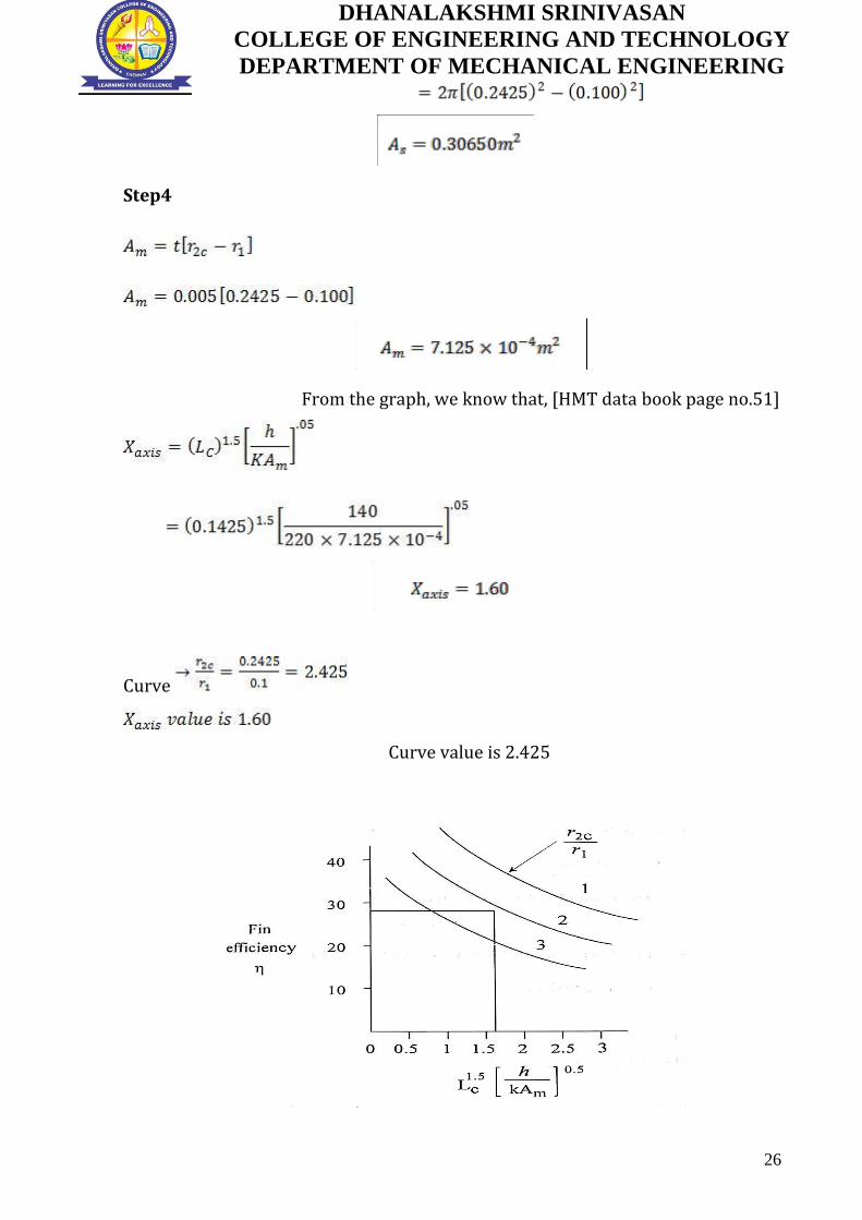
Step4
From the graph, we know that, [HMT data book page no.51]
Curve
Curve value is 2.425
26
DHANALAKSHMI SRINIVASAN
COLLEGE OF ENGINEERING AND TECHNOLOGY
DEPARTMENT OF MECHANICAL ENGINEERING
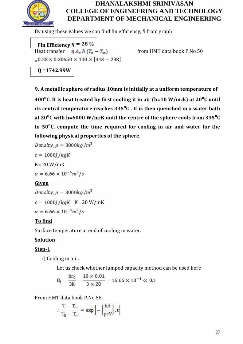
By using these values we can find fin efficiency, from graph
Fin Efficiency
Heat transfer from HMT data book P.No 50
=
Q =1742.99W
9. A metallic sphere of radius 10mm is initially at a uniform temperature of
400⁰C. It is heat treated by first cooling it in air (h=10 W/m2k) at 20⁰C until
its central temperature reaches 335⁰C . It is then quenched in a water bath
at 20⁰C with h=6000 W/m2K until the centre of the sphere cools from 335⁰C
to 50⁰C. compute the time required for cooling in air and water for the
following physical properties of the sphere.
K= 20 W/mK
Given
K= 20 W/mK
To find
Surface temperature at end of cooling in water.
Solution
Step-1
i) Cooling in air .
Let us check whether lumped capacity method can be used here
From HMT data book P.No 58
27

DHANALAKSHMI SRINIVASAN
COLLEGE OF ENGINEERING AND TECHNOLOGY
DEPARTMENT OF MECHANICAL ENGINEERING
Step-2
ii) Cooling in water
So the lumped capacity method cannot be employed, but heisler charts can be
used
.
The surface temperature at the end of quenching in water may be obtained from
fig with
28
DHANALAKSHMI SRINIVASAN
COLLEGE OF ENGINEERING AND TECHNOLOGY
DEPARTMENT OF MECHANICAL ENGINEERING
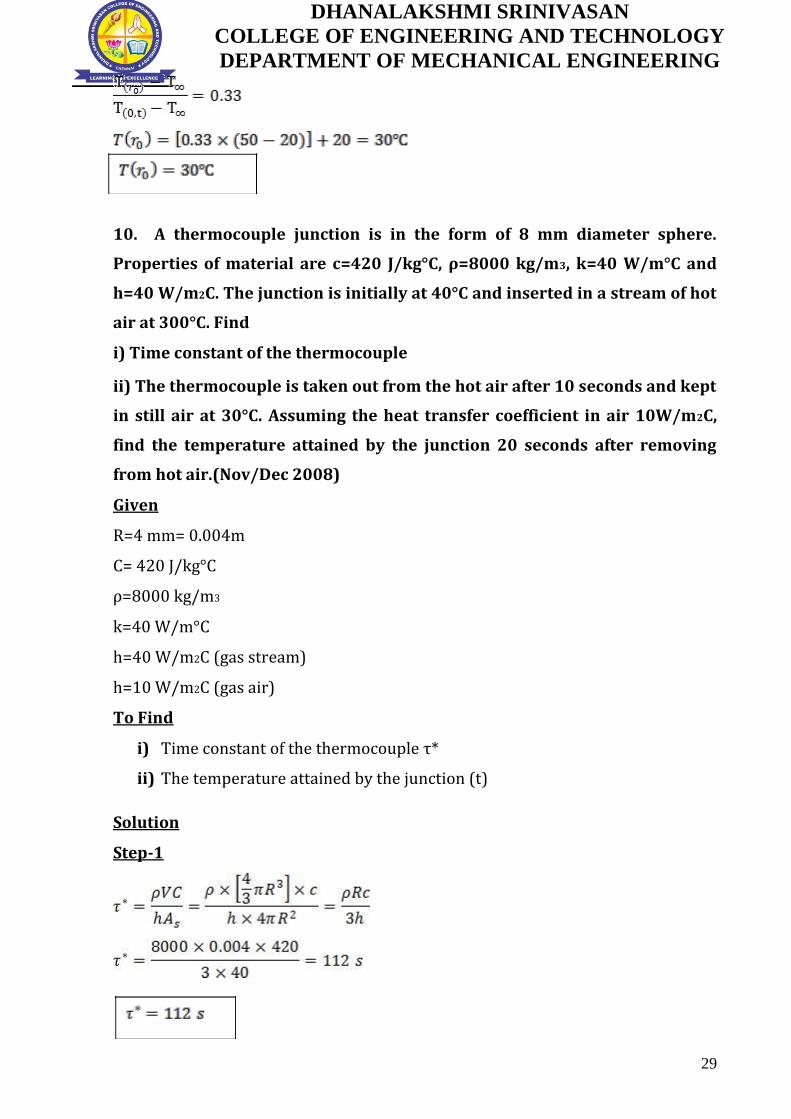
10. A thermocouple junction is in the form of 8 mm diameter sphere.
Properties of material are c=420 J/kg°C, ρ=8000 kg/m3, k=40 W/m°C and
h=40 W/m2C. The junction is initially at 40°C and inserted in a stream of hot
air at 300°C. Find
i) Time constant of the thermocouple
ii) The thermocouple is taken out from the hot air after 10 seconds and kept
in still air at 30°C. Assuming the heat transfer coefficient in air 10W/m2C,
find the temperature attained by the junction 20 seconds after removing
from hot air.(Nov/Dec 2008)
Given
R=4 mm= 0.004m
C= 420 J/kg°C
ρ=8000 kg/m3
k=40 W/m°C
h=40 W/m2C (gas stream)
h=10 W/m2C (gas air)
To Find
i) Time constant of the thermocouple τ*
ii) The temperature attained by the junction (t)
Solution
Step-1
29

DHANALAKSHMI SRINIVASAN
COLLEGE OF ENGINEERING AND TECHNOLOGY
DEPARTMENT OF MECHANICAL ENGINEERING
Step-2
The temperature variation with respect to time during heating (when dipped in
gas stream) is given by
From HMT data book P.No 58
The temperature variation with respect to time during cooling (when exposed to
air) is given by
Where
30

DHANALAKSHMI SRINIVASAN
COLLEGE OF ENGINEERING AND TECHNOLOGY
DEPARTMENT OF MECHANICAL ENGINEERING
PART C - 15 Marks (Questions and Answers)
1. Heat Conduction in the Base Plate of an Iron Consider the base plate of a
1200-W household iron that has a thickness of L 0.5 cm, base area of A 300
cm2, and thermal conductivity of k 15 W/m · °C. The inner surface of the
base plate is subjected to uniform heat flux generated by the resistance
heaters inside, and the outer surface loses heat to the surroundings at T
20°C by convection, as shown in Figure
Taking the convection heat transfer coefficient to be h 80 W/m2 · °C and
disregarding heat loss by radiation, obtain an expression for the variation of
temperature in the base plate, and evaluate the temperatures at the inner and the
outer surfaces.
SOLUTION
The base plate of an iron is considered. The variation of temperature in the
plate and the surface temperatures are to be determined. Assumptions
1 Heat transfer is steady since there is no change with time.
2 Heat transfer is one-dimensional since the surface area of the base plate is large
relative to its thickness, and the thermal conditions on both sides are uniform.
3 Thermal conductivity is constant.
4 There is no heat generation in the medium.
5 Heat transfer by radiation is negligible.
6 The upper part of the iron is well insulated so that the entire heat generated in
the resistance wires is transferred to the base plate through its inner surface.
Properties
31

DHANALAKSHMI SRINIVASAN
COLLEGE OF ENGINEERING AND TECHNOLOGY
DEPARTMENT OF MECHANICAL ENGINEERING
The thermal conductivity is given to be k 15 W/m · °C.
Analysis The inner surface of the base plate is subjected to uniform heat flux at a
rate of
q0 = 40,000 W/m2
The outer side of the plate is subjected to the convection condition. Taking the
direction normal to the surface of the wall as the x-direction with its origin on the
inner surface, the differential equation for this problem can be expressed as fig
With the boundary conditions
[ T(L) -
The general solution of the differential equation is again obtained by
two successive integrations to be
And
T(x) = C1x + C2 -------(1)
Where C1 and C2 are arbitrary constants. Applying the first boundary condition,
-KC1 = q0 C1 = -
[ T(L) -
-KC1 =h[(C1L + C2) -
32
DHANALAKSHMI SRINIVASAN
COLLEGE OF ENGINEERING AND TECHNOLOGY
DEPARTMENT OF MECHANICAL ENGINEERING
Substituting C1 = - and solving for C2 We obtain
C2 =
Now substituting C1 and C2 into the general solution (1) gives
T(x) = -------(2)
Which is the solution for the variation of the temperature in the plate. The
temperatures at the inner and outer surfaces of the plate are determined
by substituting x=0 and x=L, respectively, into the relation (2)
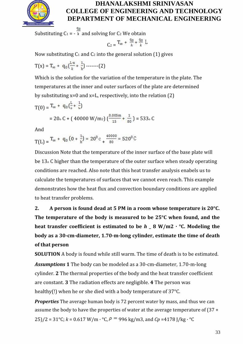
T(0) =
= 20o C + ( 40000 W/m2) ( = 533o C
And
T(L) = +
Discussion Note that the temperature of the inner surface of the base plate will
be 13o C higher than the temperature of the outer surface when steady operating
conditions are reached. Also note that this heat transfer analysis enabels us to
calculate the temperatures of surfaces that we cannot even reach. This example
demonstrates how the heat flux and convection boundary conditions are applied
to heat transfer problems.
2. A person is found dead at 5 PM in a room whose temperature is 20°C.
The temperature of the body is measured to be 25°C when found, and the
heat transfer coefficient is estimated to be h _ 8 W/m2 · °C. Modeling the
body as a 30-cm-diameter, 1.70-m-long cylinder, estimate the time of death
of that person
SOLUTION A body is found while still warm. The time of death is to be estimated.
Assumptions 1 The body can be modeled as a 30-cm-diameter, 1.70-m-long
cylinder. 2 The thermal properties of the body and the heat transfer coefficient
are constant. 3 The radiation effects are negligible. 4 The person was
healthy(!) when he or she died with a body temperature of 37°C.
Properties The average human body is 72 percent water by mass, and thus we can
assume the body to have the properties of water at the average temperature of (37 +
25)/2 = 31°C; k = 0.617 W/m · °C, 996 kg/m3, and Cp =4178 J/kg · °C
33

DHANALAKSHMI SRINIVASAN
COLLEGE OF ENGINEERING AND TECHNOLOGY
DEPARTMENT OF MECHANICAL ENGINEERING
Analysis The characteristic length of the body is
Then the biot number becomes
Bi =
Therefore lumped system analysis is not applicable. However, we can still use it to get
a rough estimate of the time of death.
-------(1)
The exponent b in this case is
b=
now substitute these values into equation (1)
t= 43860 s = 12.2 h
The person died about 12 h before the body was found and thus the time of death is 5
AM.
34

DHANALAKSHMI SRINIVASAN
COLLEGE OF ENGINEERING AND TECHNOLOGY
DEPARTMENT OF MECHANICAL ENGINEERING
UNIT: II - CONVECTION
PART A - 2 Marks (Questions and Answers)
1. Define critical Reynolds number. What is its typical value for flow over a
flat plate and flow through a pipe? (May 2013, Nov/Dec 16)
The critical Reynolds number refers to the transition from laminar to
turbulent flow.
The critical Reynolds number for flow over a flat plate is 5*105; the critical
Reynolds number for flow through a pipe is 4000.
2. How does or Distinguish laminar flow differ from turbulent flow? (May
2013 & May 2015)
Laminar flow: Laminar flow is sometimes called stream line flow. In this
type of flow, the fluid moves in layers and each fluid particle follows a smooth
continuous path. The fluid particles in each layer remain in an orderly sequence
without mixing with each other.
Turbulent flow: In addition to the laminar type of flow, a distinct irregular
flow is frequently observed in nature. This type of flow is called turbulent flow.
The path of any individual particle is zig-zag and irregular.
Velocity
Turbulent flow
Laminar flow
Time
3. Differentiate viscous sub layer and buffer layer. (May 2014)
In the turbulent boundary layer, a very thin layer next to the wall where
viscous effect is dominant called the viscous sub layer. The velocity profile in this
layer is very nearly linear and the flow is streamlined.
In the turbulent boundary layer, next to viscous sub layer, a layer called
buffer layer in which turbulent effects are becoming significant, but the flow is
still dominated by viscous effects.
35

DHANALAKSHMI SRINIVASAN
COLLEGE OF ENGINEERING AND TECHNOLOGY
DEPARTMENT OF MECHANICAL ENGINEERING
4. Define grashoff number and prandtl number. Write its significance. (May
2014 & Nov 2014 & Nov 2015-Reg 2008)(Nov 2015) (APR/MAY 2017)
Grashoff number is defined as the ratio of product of inertia force and
buoyancy force to the square of viscous force.
Gr = Inertia Force * Buoyancy Force [HMT Data Book, P.No 112]
Significance: Grashoff number has a role in free convection similar to that
played by Reynolds number in forced convection.
Prandtl number is the ratio of the momentum diffusivity of the thermal
diffusivity.
Pr = Momentum Diffusivity [HMT Data Book, P.No. 112]
Thermal Diffusivity
Significance: Prandtl number provides a measure of the relative
effectiveness of the momentum and energy transport by diffusion.
5. Define velocity boundary layer thickness. (May 2015)
The region of the flow in which the effects of the viscous shearing forces
caused by fluid viscosity are felt is called velocity boundary layer. The velocity
boundary layer thickness, δ, is defined as the distance from the surface at which
velocity, u = 0.99V
6. Air at 27OC and 1 atmospheric flow over a flat plate at a speed of 2m/s.
Calculate boundary layer thickness at a distance 40 cm from leading edge of
plate. At 27OC viscosity (air) = 1.85 *10-5 kg/ms. (Nov 2012)
Given Data:
T = 27OC = 27+273 = 300K
P = 1 atm = 1 bar = 1.01325 * 105 N/m2
U = 2 m/s
µ = 1.85 *10-5 kg/ms. (At 27OC)
R = 287 (Gas constant)
To Find: δ at X = 40 cm = 0.4 m
Solution: Step: 1 Density ρ = P/RT
= 1.01325 * 105
(287*300)
36

DHANALAKSHMI SRINIVASAN
COLLEGE OF ENGINEERING AND TECHNOLOGY
DEPARTMENT OF MECHANICAL ENGINEERING
= 1.177 Kg/m3
(Note: If Surface temperature (Tw) is given, then properties to be taken for Tf
Value.)
Step: 2 Reynolds Number Re = ρUX/ µ [HMT Data Book, P.No. 112]
= 1.177*2*0.4
1.85 *10-5
= 55160. (Re < 5*105, flow is laminar)
Step: 3 Boundary layer thickness δ = 5* X * (Re)-0.5
[HMT Data Book, P.No.113]
= 5 * 0.4 * (55160)-0.5
= 0.0085 m
Boundary layer thickness δ at X (0.4m) = 0.0085 m
7. A square plate 40*40 cm maintained at 400K is suspended vertically in
atmospheric air at 300 K. Determine the boundary layer thickness at
trailing edge of the plate. (Nov 2012)
Given Data:
Length of horizontal plate X = 40 cm =
0.4m Wide W = 40 cm = 0.40 m
Plate temperature Tw = 400K = 1270C
Fluid temperature Tα = 300K = 270C
ΔT = (Tw- Tα) = 400-300 = 100
To Find: δ at X = 40 cm = 0.4 m
Solution:
Step: 1 Film Temperature (Tf) = Tw+ Tα
2
= 127+27 = 770C = 350K
2
Step: 2 Properties of air at 770C (apprx 750C)
[HMT Data Book, P.No.34]
37

DHANALAKSHMI SRINIVASAN
COLLEGE OF ENGINEERING AND TECHNOLOGY
DEPARTMENT OF MECHANICAL ENGINEERING
ν = 20.56 * 10-6
m2/s Pr = 0.693
= 1 / 350
= 2.857 * 10-3 K-1
ν2
= 9.81 * 2.857 * 10-3 * (0.4)3 * (400-300)
(20.56 * 10-6)2
= 4.24 * 108
Step: 5 Boundary layer thickness δ = 3.93 * X * (Pr)-0.5 * (0.952+Pr)0.25 * Gr-0.25
[HMT Data Book, P.No.135]
= 3.93 * 0.4 * (0.693) -0.5 * (0.952+0.693)0.25 * (4.24*108)-0.25
= 0.0155 m
Boundary layer thickness δ at X (0.4m) = 0.0155 m
8. Define the term thermal boundary layer thickness. (Nov 2013)
The thickness of the thermal boundary layer δt at any location along the
surface is defined as the distance from the surface at which the temperature
difference equals to 0.99(Tα-Ts), in general T=0.99Tα
9. Why heat transfer coefficient for natural convection is much lesser than
that for forced convection? (Nov 2013 & May 2016)
Heat transfer coefficient depends on the fluid velocity.
In natural convection, the fluid motion occurs by natural means such as
buoyancy. Since the fluid velocity associated with natural convection is relatively
low, the heat transfer coefficient encountered in natural convection is low.
The reason for higher heat transfer rates in forced convection is because
the hot air surrounding the hot body is immediately removed by the flow of air
around it. This is why forced convection heat transfer coefficient is greater than
natural convection heat transfer coefficient.
38

DHANALAKSHMI SRINIVASAN
COLLEGE OF ENGINEERING AND TECHNOLOGY
DEPARTMENT OF MECHANICAL ENGINEERING
10. Name four dimensions used for dimensional analysis. (Nov 2014)
1. Velocity
2. Density
3. Heat transfer coefficient
4. Thermal conductivity
11. Mention the significance of boundary layer. (Nov 2015)
Boundary layer is the layer of fluid in the immediate vicinity of a bounding
surface where the effects of viscosity are significant.
12. What is Dittus Boelter equation? When does it apply? (Nov 2015)
Dittus-Boelter equation (for fully developed internal flow - turbulent flow)
is an explicit function for calculating the Nusselt number. It is easy to solve but is
less accurate when there is a large temperature difference across the fluid. It is
tailored to smooth tubes, so use for rough tubes (most commercial applications)
is cautioned.
The Dittus-Boelter equation is:
NuD=0.023 ReD 0.8 Prn [HMT Data Book, P.No.126]
13. What is the difference between friction factor and friction coefficient?
(May 2016)
Friction factor, a dimensionless quantity used in the Darcy–Weisbach
equation, for the description of friction losses in pipe flow as well as open-
channel flow. Friction coefficient applied at the value of x (x=x-Local friction
coefficient, x=L – Average friction coefficient)
14. Differentiate free and forced convection. (May 2016) ( Nov/Dec 16)
Natural convection, or free convection, occurs due to temperature
differences which affect the density, and thus relative buoyancy, of the fluid. Free
convection is governed by Grashoff number and Prandtl number.
Example: Rise of smoke from a fire.
In forced convection, fluid movement results from external forces such as a
fan or pump. Forced convection is typically used to increase the rate of heat
exchange. It is governed by the value of the Reynolds number.
Example: Cooling of IC engines with fan in a radiator.
39

DHANALAKSHMI SRINIVASAN
COLLEGE OF ENGINEERING AND TECHNOLOGY
DEPARTMENT OF MECHANICAL ENGINEERING
15. Differentiate hydrodynamic and thermal boundary layer. (May 2016)
The hydrodynamic boundary layer is a region of a fluid flow, near a solid
surface, where the flow patterns (velocity) are directly influenced by viscous drag
from the surface wall. The velocity of the fluid is less than 99% of free stream
velocity.
The thermal boundary layer is a region of a fluid flow, near a solid surface,
where the fluid temperatures are directly influenced by heating or cooling from
the surface wall. The temperature of the fluid is less than 99% of free stream
temperature.
16. What are the difference between natural convection and forced
convection? ( Nov/Dec 16)
Natural convection is a mechanism of heat transportation in which the
fluid motion is not generated by an external source.
Forced convection is a mechanism, or type of heat transport in which fluid
motion is generated by an external source (like a pump, fan, suction device, etc.)
PART B - 13 Marks (Questions and Answers)
1. Air at 250C at the atmospheric pressure is flowing over a flat plat at 3m/s.
If the plate is 1m wide and the temperature Tw = 750C. Calculate the
following at a location of 1m from leading edge.
a) Hydrodynamic boundary layer thickness,
b) Local friction coefficient,
c) Thermal heat transfer coefficient,
d) Local heat transfer coefficient.
Given Data:
Fluid temperature, Tα =250C
Velocity, U=3m/s
Wide, W = 1m
Plate surface temperature, Tw=750C
Distance, x = 1m
To Find: δhx , Cfx, δTx , hx ,
40

DHANALAKSHMI SRINIVASAN
COLLEGE OF ENGINEERING AND TECHNOLOGY
DEPARTMENT OF MECHANICAL ENGINEERING
Solution: [From HMT Data Book, P.No.113]
Film temperature, Tf =
= 323K
Tf = 500C
Properties of air at 500C:
[From HMT Data Book, P.No.34]
Density, ρ =1.093kg/m3
Kinematic viscosity, v=17.95 x 10⁻⁶ m2/s
Prandtl number Pr=0.698
Thermal conductivity, k =0.02826 W/mk
Reynolds number, Re =UL/v [From HMT Data Book, P.No.112]
[∵x=L=1m]
=1.67*105
Re=1.67*105<5*105
Since Re=<5*105 flow is laminar.
For the plate, laminar flow.
[From HMT Data Book, P.No.113 ]
1. Hydrodynamic boundary layer thickness,
δhx =5*x* Re-0.5 =5*x*
(1.67*105)-0.5
δhx =0.0122m
2. Local friction coefficient, [From HMT Data Book, P.No.113 ]
Cfx, =0.664 Re-0.5
=0.664*(1.67*105)-0.5
Cfx, =1.62*10-3
3. Thermal heat transfer coefficient,
[From HMT Data Book, P.No.113]
41

DHANALAKSHMI SRINIVASAN
COLLEGE OF ENGINEERING AND TECHNOLOGY
DEPARTMENT OF MECHANICAL ENGINEERING
δTx = δhx * (Pr)-0.333
=0.0122*(0.698)-0.333
δTx =0.01375
4. Local heat transfer coefficient, hx
[From HMT Data Book, P.No.113]
Local nusselt number Nux = 0.332 Re0.5 (Pr)0.333
= 0.332 (1.67*105)0.5 (0.698)0.333
Nux = 120.415
[From HMT Data Book, P.No.112]
Nux=
120.415= [∵x=L=1m]
Local heat transfer coefficient, hx =3.4W/m2K
Result:
a) δhx =0.0122m
b) Cfx, =1.62*10-3 c) δTx =0.01375
d) h =3.4W/m2K
2. Air at 290C flows over a flat plate at a velocity of 6 m/s. The plate is 1m
long and 0.5 m wide. The pressure of the air is 6 KN/m2. If the plate is
maintained at a temperature of 70C, estimate the rate of heat removed
from the plate.
Given:
Fluid temperature T = 290C
Velocity U = 6 m/s.
Length L = 1 m
Wide W= 0.5 m
Pressure of air P = 6 KN/m2 6 103 N/ m
2
42

DHANALAKSHMI SRINIVASAN
COLLEGE OF ENGINEERING AND TECHNOLOGY
DEPARTMENT OF MECHANICAL ENGINEERING
Plate surface temperature Tw = 70C
To find:
Heat removed from the plate
Solution:
[From HMT Data Book, P.No.113]
Film temperature Tf =
Tf =
Tf=180C
Properties of air at 180C (At atmospheric pressure)
[From HMT Data Book, P.No.34]
0.799 Kg/m3
= 32.49 10
-6 m
2 /
s Pr 0.681
K 37.80 10-3
W/mK
Note: Pressure other than atmospheric pressure is given, so kinematic viscosity
will vary with pressure. Pr, K, Cp are same for all pressures.
Kinematic viscosity [∵1 bar=1×10⁵N/m2]
Kinematic viscosity =5.145×10⁻⁴m2/s
[From HMT Data Book, P.No.112]
Reynolds number Re=
Re = 1.10×10⁴-5×10⁵
Since Re<5×10⁵,flow is laminar
For plate, laminar flow, UL ν
[From HMT Data Book, P.No.113]
Local nusselt number Nux =0.332 Re0.5 (Pr)0.333
=0.332 (1.10×10⁴)0.5 (0.681)0.333
43

DHANALAKSHMI SRINIVASAN
COLLEGE OF ENGINEERING AND TECHNOLOGY
DEPARTMENT OF MECHANICAL ENGINEERING
Nux=30.63
[From HMT Data Book, P.No.112]
NUx=
30.63
h x 1
[ L = 1 m]
37.80 103
Local heat transfer coefficient hx =1.15 W/m2K
Average heat transfer coefficient h = 2hx
h = 21.15
h = 2.31W/m2K
Heat transferred Q= h A (Tα -Tw)
=2.13×(1×0.5)× (563-343)
Q=254.1W
Heat transfer from both side of the plate = 2 254.1
= 508.2 W.
Result: Heat transfer from both side of the plate = 508.2 W
3. A large vertical plate 4 m height is maintained at 606C and exposed to
atmospheric air at 106C. alculate the heat transfer is the plate is 10 m wide.
Given :
Vertical plate length (or) Height, L = 4
m Wall temperature, Tw = 606C
Air temperature, T = 106C
Wide, W = 10 m
To find:
a) Heat transfer, (Q)
Solution: [From HMT Data Book, P.No.113]
Film temperature Tf =
Tf =356C
44

DHANALAKSHMI SRINIVASAN
COLLEGE OF ENGINEERING AND TECHNOLOGY
DEPARTMENT OF MECHANICAL ENGINEERING
[From HMT Data Book, P.No.34 ]
Properties of air at 356C = 350C
Density, ρ =0.566kg/m3
Kinematic viscosity, v=55.46 x 10⁻⁶ m2/s
Prandtl number Pr=0.698
Thermal conductivity, k =49.08 x 10⁻³W/mk
Coefficient of thermal expansion β =
1
1
356 273 629
= 1.58 10-3
K1
Grashof number Gr = g
L
3 T
v2
Gr = 9.81 2.4 10-3
(4)3 (606 106)
(55.46 106
)2
Gr = 1.61 1011
Gr Pr = 1.61 1011 0.676
Gr Pr = 1.08 1011
Since Gr Pr > 109, flow is turbulent
For turbulent flow,
Nusselt number Nu = 0.10 [Gr Pr]0.333
Nu = 0.10 [1.08 1011
]0.333
Nu = 471.20
[From HMT Data Book, P.No.112]
Nusselt number Nu hL
K
472.20 =
h 4
49.08 10-3
Heat transfer coefficient h = 5.78 W/m2K
Heat transfer Q = h A T
=h× W × L× (Tw - T )
=5.78×10×4× (606-106)
Q =115600 W
45

DHANALAKSHMI SRINIVASAN
COLLEGE OF ENGINEERING AND TECHNOLOGY
DEPARTMENT OF MECHANICAL ENGINEERING
Q =115.6×10³ W
Result:
Heat transfer Q=115.6×10³ W
4. A thin 100 cm long and 10 cm wide horizontal plate is maintained at a
uniform temperature of 150C in a large tank full of water at 75C. Estimate
the rate of heat to be supplied to the plate to maintain constant plate
temperature as heat is dissipated from either side of plate.
Given :
Length of horizontal plate, L = 100 cm = 1m
Wide, W = 10 cm = 0.10 m Plate
temperature, Tw = 150C Fluid
temperature, T = 75C
To find:
a) Heat loss (Q) from either side of plate
Solution:
Film temperature, Tf =
[From HMT Data Book, P.No.113]
=
323K
Tf = 112.50C
Properties of water at 112.50C
Ρ =951Kg/m3
V= 0.264×10⁻⁶ m2/s
Pr =1.55
K=683×10-3W/mK
Coefficient of thermal expansion β = = = 2.59×10⁻³k-1
46

DHANALAKSHMI SRINIVASAN
COLLEGE OF ENGINEERING AND TECHNOLOGY
DEPARTMENT OF MECHANICAL ENGINEERING
Grashof Number Gr = g
L
3 T
v2
For horizontal plate, W 0.10
Lc = 0.05 m
Gr=
Gr=3.41×10⁹
GrPr=3.14×109×1.55
Gr Pr = 5.29 109
Gr Pr value is in between 8 106 and 1011
i.e., 8 106 < Gr Pr < 1011
For horizontal plate, upper surface heated:
Nusselt number Nu = 0.15 (Gr Pr)0.333
[From HMT Data Book, P.No.114 ]
Nu = 0.15 (5.29×10⁹)0.333
Nu =259.41
Nusselt number Nu = h
uL
c
K
259.41 h
u 0.05
683 103
hu = 3543.6 W/m2K
Upper surface heated, heat transfer coefficient hu = 3543.6 W/m2K
For horizontal plate, lower surface heated:
Nusselt number Nu = 0.27 [Gr Pr]0.25
Nu = 0.27 [5.29× 10⁹]0.25
Nu =72.8
[From HMT Data Book, P.No.113]
Nusselt number Nu =
72.8 =
72.8 =
47

DHANALAKSHMI SRINIVASAN
COLLEGE OF ENGINEERING AND TECHNOLOGY
DEPARTMENT OF MECHANICAL ENGINEERING
= 994.6W/m2K
Lower surface heated, heat transfer coefficient h1 = 994.6
W/m2K Total heat transfer Q = (hu + h1) A T
= (hu + h1) W L (Tw - T)
= (3543.6 + 994.6) 0.10 (150 –
75) Q = 34036.5 W
Result:
Total heat transfer Q = 34036.5 W
5. Explain in detail about the boundary layer concept.
The concept of a boundary layer as proposed by prandtl forms the
starting point for the simplification of the equation of motion and energy.
When a real i.e., viscous fluid, flow along a stationary solid boundary, a layer of
fluid which comes in contact with boundary surface and undergoes retardation
this retarded layer further causes retardation for the adjacent layer of the fluid.
So small region is developed in the immediate vicinity of the boundary surface in
which the velocity of the flowing fluid increases rapidly from zero at boundary
surface and approaches the velocity of main stream.
Types of boundary layer
1. Velocity boundary layer (or)hydrodynamic boundary layer
2. Thermal boundary layer
Velocity boundary layer (or) hydrodynamic boundary layer
In the Velocity boundary layer, velocity of the fluid is less than 99% of free
steam velocity.
The fluid approaches the plate in x direction with uniform velocity u∞. The
fluid particles in the fluid layer adjacent to the surface get zero velocity. This
motionless layer acts to retard the motion of particles in the adjoining fluid layer
as a result of friction between the particles of these two adjoining fluid layers at
two different velocities. This fluid layer then acts to retard the motion of particles
of next fluid layer and so on, until a distance y =d from the surface reaches, where
48
DHANALAKSHMI SRINIVASAN
COLLEGE OF ENGINEERING AND TECHNOLOGY
DEPARTMENT OF MECHANICAL ENGINEERING
these effects become negligible and the fluid velocity u reaches the free stream
velocity u∞ as a result of frictional effects between the fluid layers.
Thermal boundary Layer:
In the Thermal boundary layer, temperature of the fluid is less than 99%
of free steam temperature.
If the fluid flowing on a surface has a different temperature than the
surface, the thermal boundary layer developed is similar to the velocity boundary
layer. Consider a fluid at a temperature T∞ flows over a surface at a constant
temperature Ts. The fluid particles in adjacent layer to the plate get the same
temperature that of surface. The particles exchange heat energy with particles in
adjoining fluid layers and so on. As a result, the temperature gradients are
developed in the fluid layers and a temperature profile is developed in the fluid
flow, which ranges from Ts at the surface to fluid temperature T∞ sufficiently far
from the surface in y direction.
Velocity boundary layer on a flat plate:
It is most essential to distinguish between laminar and turbulent boundary
layers. Initially, the boundary layer development is laminar as shown in figure for
the flow over a flat plate. Depending upon the flow field and fluid properties, at
some critical distance from the leading edge small disturbances in the flow begin
to get amplified, a transition process takes place and the flow becomes turbulent.
In laminar boundary layer, the fluid motion is highly ordered whereas the motion
in the turbulent boundary layer is highly irregular with the fluid moving to and
from in all directions. Due to fluid mixing resulting from these macroscopic
motions, the turbulent boundary layer is thicker and the velocity profile in
turbulent boundary layer is flatter than that in laminar flow.
49

DHANALAKSHMI SRINIVASAN
COLLEGE OF ENGINEERING AND TECHNOLOGY
DEPARTMENT OF MECHANICAL ENGINEERING
Velocity boundary layer on a tube:
Laminar Boundary Layer Flow
The laminar boundary is a very smooth flow, while the turbulent boundary layer
contains swirls or "eddies." The laminar flow creates less skin friction drag than
the turbulent flow, but is less stable. Boundary layer flow over a wing surface
begins as a smooth laminar flow. As the flow continues back from the leading
edge, the laminar boundary layer increases in thickness. Turbulent Boundary
Layer Flow
At some distance back from the leading edge, the smooth laminar flow breaks
down and transitions to a turbulent flow. From a drag standpoint, it is advisable
to have the transition from laminar to turbulent flow as far aft on the wing as
possible, or have a large amount of the wing surface within the laminar portion of
the boundary layer. The low energy laminar flow, however, tends to break down
more suddenly than the turbulent layer.
Thermal boundary Layer on a flat plate:
Consider a fluid of uniform temperature Tα approaching a flat plate of constant
temperature Ts in the direction parallel to the plate. At the solid/liquid interface
50

DHANALAKSHMI SRINIVASAN
COLLEGE OF ENGINEERING AND TECHNOLOGY
DEPARTMENT OF MECHANICAL ENGINEERING
the fluid temperature is Ts since the local fluid particles achieve thermal
equilibrium at the interface. The fluid temperature T in the region near the plate
is affected by the plate, varying from Ts at the surface to Tα in the main stream.
This region is called the thermal boundary layer.
Velocity and Temperature boundary layer (Profile) for a vertical plate
51

DHANALAKSHMI SRINIVASAN
COLLEGE OF ENGINEERING AND TECHNOLOGY
DEPARTMENT OF MECHANICAL ENGINEERING
6. In a long annulus (3.125 cm ID and 5 cm OD) the air is heated by
maintaining the temperature of the outer surface of inner tube at 50C. The
air enters at 16C and leaves at 32C. Its flow rate is 30 m/s. Estimate the
heat transfer coefficient between air and the inner tube.
Given : Inner diameter Di = 3.125 cm = 0.03125
m Outer diameter Do = 5 cm = 0.05 m
Tube wall temperature Tw = 50C
Inner temperature of air Tmi = 16C
Outer temperature of air tmo = 32C
Flow rate U = 30 m/s
To find: Heat transfer coefficient (h)
Solution:
Step 1. Mean temperature Tm =
=
Tm = 24°C
Properties of air at 24°C [From HMT Data book page no. 34]
ρ = 1.185 Kg/m3
ν = 15.53 x 10⁻⁶ m2/s
Pr = 0.702
k = 0.02634 W/mK
Step 2. Hydraulic or Equivalent diameter
Dh = =
=
= Do - Di
= 0.05 – 0.03125
Dh = 0.01875 m
Step 3. Reynolds number, Re =
=
52

DHANALAKSHMI SRINIVASAN
COLLEGE OF ENGINEERING AND TECHNOLOGY
DEPARTMENT OF MECHANICAL ENGINEERING
Re = 36.2 x 10³
Since Re > 2300, flow is turbulent.
For turbulent flow, general equation is (Re > 10000).
Nu = 0.023 (Re)0.8 (Pr)n
[From HMT Data book, Page No. 126]
This is heating process. So n = 0.4. [Tmo > Tmi] Step 4. Nu
= 0.023 x (36.2 X 103)0.8 (0.702)0.4
Nu = 88.59
Step 5. Nu =
88.59 =
h = 124.4 W/m2K
Heat transfer coefficient, h = 124.4 W/m2K
7. In a surface condenser, water flows through staggered tubes while the air
is passed in cross flow over the tubes. The temperature and velocity of air
are 30°C and 8 m/s respectively. The longitudinal and transverse pitches
are 22 mm and 20 mm respectively. The tube outside diameter is 18 mm
and tube surface temperature is 90°C. Calculate the heat transfer
coefficient.
Given:
Fluid temperature, T∞ = 30°C
Velocity, U = 8 m/s
Longitudinal pitch, Sl = 22 mm = 0.022 mm
Transverse pitch, St = 20 mm = 0.020 m
Diameter, D = 18 mm = 0.018 m
Tube surface temperature, Tw = 90°C
53

DHANALAKSHMI SRINIVASAN
COLLEGE OF ENGINEERING AND TECHNOLOGY
DEPARTMENT OF MECHANICAL ENGINEERING
To find:
Step 1. Heat transfer coefficient.
Solution:
We know that,
Film temperature, Tf =
= Tf = 60°C
Properties of air at 60°C
[From HMT data book, Page No. 34]
ν = 18.97 x 10⁻⁶ m2/s
Pr = 0.696
K = 0.02896 W/mK
Step 2. Maximum velocity, Umax = U x
Umax = 8 x
Umax = 80 m/s
Step 3. Reynolds Number, Re =
=
Re = 7.5 x 104
= = 1.11
= 1.11
= = 1.22
= 1.22
= 1.11, = 1.22, corresponding C, n values are 0.518 and 0.556 respectively.
[From HMT data book, page No. 123 ]
54

DHANALAKSHMI SRINIVASAN
COLLEGE OF ENGINEERING AND TECHNOLOGY
DEPARTMENT OF MECHANICAL ENGINEERING
C = 0.518 n = 0.556
Step 4. Nusselt Number, Nu = 1.13 (Pr)0.333 [ C (Re)n]
[From HMT data dook, Page No. 123 ]
Nu = 1.13x(0.696)0.333x[ 0.518 x (7.5 x 104)0.556]
Nu = 266.3
Step 5. Nusselt Number, Nu =
266.3 =
Heat transfer coefficient, h = 428.6 W/m2K
8. A thin 100 cm long and 10 cm wide horizontal plate is maintained at a
uniform temperature of 150ºC in a large tank full of water at 75ºC. Estimate
the rate of heat to be supplied to the plate to maintain constant plate
temperature as heat is dissipated from either side of plate.
Given:
Length of horizontal plate L = 100 cm = 1m
Wide W = 10 cm = 0.10 m Plate
temperature Tw = 150ºC Fluid
temperature T∞ = 75ºC
To find: Heat loss (Q) from either side of plate:
Solution:
Step 1. Film temperature, Tf =
=
Tf = 112.5ºC
Properties of water at 112.5ºC:
[From HMT data book, Page No. 22]
ρ = 951 Kg/m3
ν = 0.264 x 10⁻⁶ m2/s
55

DHANALAKSHMI SRINIVASAN
COLLEGE OF ENGINEERING AND TECHNOLOGY
DEPARTMENT OF MECHANICAL ENGINEERING
Pr = 1.55
k = 0.683 W/mK
β(for water) = 0.8225 x 10⁻³ K-1
[From HMT data book, Page No. 30]
Step 2. Grashof Number, Gr =
For horizontal plate,
Characteristic length, Lc = =
Lc = 0.05 m
Gr =
Gr = 1.0853 x 10⁹
GrPr = 1.0853 x 109 x 1.55
GrPr = 1.682 x 10⁹
GrPr value is in between 8 x 10⁶ and 1011
i.e., 8 x 10⁶ < GrPr <1011
For horizontal plate, upper surface heated:
Step 3. Nusselt Number, Nu = 0.15 (GrPr)0.333
[From HMT data book, Page No. 136]
Nu = 0.15 [1.682 x 10⁹]0.333
Nu = 177.13
Step 4. Nusselt Number, Nu =
177.13 =
hu = 2419.7 W/m2K
Upper surface heated, heat transfer coefficient
hu = 2419.7 W/m2K
For horizontal plate, lower surface heated:
Step 5. Nusselt Number Nu = 0.27 [GrPr]0.25
[From HMT data book, Page No. 136]
Nu = 0.27 [1.682 109]0.25
Nu = 54.68
Step 6. Nusselt Number, Nu =
56

DHANALAKSHMI SRINIVASAN
COLLEGE OF ENGINEERING AND TECHNOLOGY
DEPARTMENT OF MECHANICAL ENGINEERING
54.68 =
hl = 746.94 W/m2K
Lower surface heated, heat transfer coefficient, hl = 746.94 W/m2K
Step 7. Total heat transfer, Q = (hu + hl) x A x ΔT
= (hu + hl) x W x L x (Tw - )
= (2419.7 + 746.94) X 0.10 X (150-75)
Heat transfer, Q = 23749.8 W
9. Atmospheric air at 275 K and a free stream velocity of 20 m/s flows over
a flat plate 1.5 m long that is maintained at a uniform temperature of 325 K.
Calculate the average heat transfer coefficient over the region where the
boundary layer is laminar, the average heat transfer coefficient over the
entire length of the plate and the total heat transfer rate from the plate to
the air over the length 1.5 m and width 1 m. Assume transition occurs at Rec
= 2 x 10⁵.
Given: Fluid temperature, T∞ = 275 K = 2ºC
Velocity, U = 20 m/s
Length, L = 1.5 m
Plate surface temperature, Tw = 325 K = 52°C
Width, W = 1 m
Critical Reynolds number, Rec = 2 x 10⁵
To find: 1. Average heat transfer coefficient, hl [Boundary layer is laminar]
2. Average heat transfer coefficient, ht [Entire length of the plate]
3. Total heat transfer rate, Q.
Solution:
Step 1. Film temperature, Tf =
=
57
DHANALAKSHMI SRINIVASAN
COLLEGE OF ENGINEERING AND TECHNOLOGY
DEPARTMENT OF MECHANICAL ENGINEERING
Tf = 27ºC
Properties of air at 27ºC ≈ 25ºC
[From HMT data book, Page No. 34 ]
ρ = 1.185 Kg/m3
ν = 15.53 x 10⁻⁶ m2/s
Pr = 0.702
k = 0.02634 W/mK
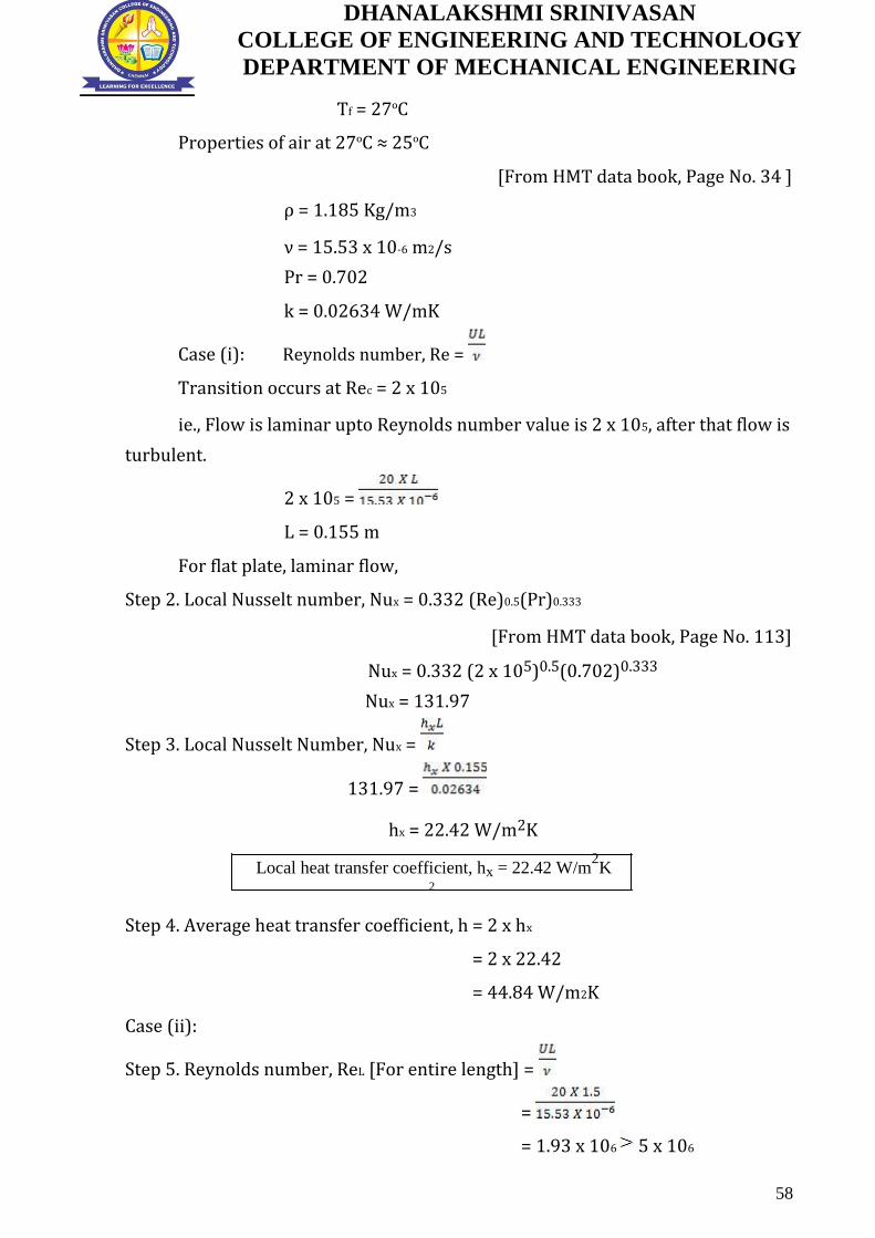
Case (i): Reynolds number, Re =
Transition occurs at Rec = 2 x 10⁵
ie., Flow is laminar upto Reynolds number value is 2 x 10⁵, after that flow is
turbulent.
2 x 105 =
L = 0.155 m
For flat plate, laminar flow,
Step 2. Local Nusselt number, Nux = 0.332 (Re)0.5(Pr)0.333
[From HMT data book, Page No. 113]
Nux = 0.332 (2 x 10⁵)0.5(0.702)0.333
Nux = 131.97
Step 3. Local Nusselt Number, Nux =
131.97 =
hx = 22.42 W/m2K
Local heat transfer coefficient, hx = 22.42 W/m2K
2
Step 4. Average heat transfer coefficient, h = 2 x hx
= 2 x 22.42
= 44.84 W/m2K
Case (ii):
Step 5. Reynolds number, ReL [For entire length] =
=
= 1.93 x 10⁶ 5 x 10⁶
58

DHANALAKSHMI SRINIVASAN
COLLEGE OF ENGINEERING AND TECHNOLOGY
DEPARTMENT OF MECHANICAL ENGINEERING
Since ReL 5 x 10⁵, flow is turbulent.
For flat plate, laminar-turbulent combined flow,
Step 6. Average Nusselt number, Nu = (Pr)0.333 [0.037 (ReL)0.8-871]
Nu = (0.702)0.333[0.037 (1.93 x 10⁶)0.8-871]
Nu = 2737.18
Step 7. Nusselt number, Nu =
2737.18 =
h = 48.06 W/m2K
Average heat transfer coefficient for turbulent flow, ht = 48.06 W/m2K
2 2
Step 8. Total heat transfer rate, Q = ht x A x
= ht x W x L x (Tw- T∞)
= 48.06 x 1 x 1.5 x (52-
2) Q = 3604.5 W
10. A steam pipe 10 cm outside diameter runs horizontally in a room at
23 ºC. Take the outside surface temperature of pipe as 165ºC. Determine the
heat loss per metre length of the pipe. [Dec 2004]
Given: Diameter of the pipe, D = 10 cm = 0.10 m
Ambient air temperature, T∞ = 23ºC
Wall temperature, Tw = 165ºC
To find: Heat loss per metre length.
Solution:
Step 1. Film temperature, Tf =
=
Tf = 94ºC
Properties of air at 94ºC≈95ºC
[From HMT data book, Page No. 34]
ρ = 0.959 Kg/m3
ν = 22.615 x 10⁻⁶ m2/s
59

DHANALAKSHMI SRINIVASAN
COLLEGE OF ENGINEERING AND TECHNOLOGY
DEPARTMENT OF MECHANICAL ENGINEERING
Pr = 0.689
k = 0.03169 W/mK
Step 2. Coefficient of thermal expansion, β =
=
= 2.72 X 10⁻³ K-1
β = 2.72 X 10⁻³ K-1
Step 3. Grashof Number, Gr =
[From HMT data book, Page No. 135]
Gr =
Gr = 7.40 x 10⁶
GrPr = 7.40 x 106 x 0.689
GrPr = 5.09 x 10⁶
For horizontal cylinder, Nusselt number, Nu = C
[From HMT data book, Page No. 138]
GrPr = 5.09 x 10⁶, corresponding C = 0.48, and m = 0.25
Nu = 0.48 [5.09 x 10⁶]0.25
Nu = 22.79
tep 4. Nusselt number, Nu =
22.79 =
h = 7.22 W/m2K
Step 5. Heat loss, Q = hA
= h x DL(Tw-T∞)
= h x x D x (Tw-T∞)
= 7.22 x x 0.10 x (165 -23)
= 322.08 W/m
Heat loss per metre length, = 322.08 W/m
60

DHANALAKSHMI SRINIVASAN
COLLEGE OF ENGINEERING AND TECHNOLOGY
DEPARTMENT OF MECHANICAL ENGINEERING
PART C – 15 Marks (Questions and Answers)
1. Consider the flow of oil at 20o C in a 30cm diameter pipeline at an
average velocity of 2 m/s. a 200m long section of the pipeline passes
through icy waters of a lake at 0o C. Measurements indicate that the
surface temperature of the pipe is very nearly 0o C. Disregarding the
thermal resistance of the pipe material determine (a) the temperature
of the oil when the pipe leaves the lake, (b) the rate of heat transfer from
the oil, and (c) the pumping power required to overcome the pressure
losses and to maintain the flow of the oil in the pipe.
Solution
Oil flows in a pipeline that passes through icy waters of a lake at 00 C. The exit
temperature of the oil, the rate of heat loss, and the pumping power needed
to overcome pressure losses are to be determined.
Assumptions
1. Steady operating conditions exist. 2. The surface temperature of the pipe
is very nearly 0o C. 3. The thermal resistance of the pipe is negligible.4. The
inner surfaces of the pipeline are smooth. 5. The flow is hydrodynamically
developed when the pipeline reaches the lake.
Properties
We do not know the exit temperature of the oil, and thus we cannot determine
the bulk mean temperature, which is the temperature at which the properties of
oil are to be evaluated. The mean temperature of the oil at the inlet is 20°C, and
we expect this temperature to drop somewhat as a result of heat loss to the icy
waters of the lake. We evaluate the properties of the oil at the inlet temperature,
but we will repeat the calculations, if necessary, using properties at the
evaluated bulk mean temperature. At 20° C from HMT data book
888 kg/m3 901 m2/s
k = 0.145 W/m °C Cp =1880 J/kg _ °C
Pr = 10,400
=666
which is less than the critical Reynolds number of 2300. Therefore, the flow is
61

DHANALAKSHMI SRINIVASAN
COLLEGE OF ENGINEERING AND TECHNOLOGY
DEPARTMENT OF MECHANICAL ENGINEERING
laminar, and we assume thermally developing flow and determine the
nusselt number from
= 3.66 + = 37.3
This nusselt number is considerably higher than the fully developed value of
3.66 then
h =
also we determine the exit temperature of air
from Te = Ts - (Ts - Ti) exp (-h As /m Cp) here
As = PL = DL= (0.3 m)(200 m) =188.5 m2
·
m= V = (1.009 kg/m3)(0.15 m3/s) =0.151 kg/s
Substitute As and m in Te
Te = 60 - (60 - 80) exp (-13.5 6.4/0.151 1008) = 71.3
Then the logarithmic mean temperature difference and the rate of heat loss from the air become
Tln= = -15.2°C
Q = h As Tln = (13.5 W/m2 °C)(6.4 m2)(-15.2°C) = -1313 W
Therefore, air will lose heat at a rate of 1313 W as it flows through the duct in the attic.
2. In condenser water flows through two hundred thin walled circular
tubes having inner diameter 20mm and length 6 m. the mass flow rate of
water is 160 kg/s. the water enters at 30o C and leaves at 50 o C.
Calculate the average heat transfer coefficient.
Given :
Inner diameter D =
20mm Length L = 6 m
Mass flow rate m = 160 kg/s
62

DHANALAKSHMI SRINIVASAN
COLLEGE OF ENGINEERING AND TECHNOLOGY
DEPARTMENT OF MECHANICAL ENGINEERING
Inlet water temperature Tmi = 30 o C
Outlet water temperature, Tmo = 50 o C
To find: Heat transfer coefficient (h)
Solution:
Bulk mean temperature Tm = = °C
Properties of water at °C [ from HMT data boo page no 21]
ν = 0.657 x 10⁻⁶ m2/s
Pr = 4.340
k = 0.628 W/mK
Cp = 4178 J/kg K
Reynolds Number Re = UD/ ν
m =
Velocity
U = m/
=
= 2.55 m/s
( no of tubes = 200)
Re = UD/ ν
= =77625.57
Since Re 2300, flow is turbulent
For turbulent flow, general equation is ( Re > 10000)
Nu = 0.023 [ from HMT data boo page no 125]
This is heating process so n = 0.4 (
Nu = 0.023
Nu = 337.8
Nu =
337.8 = Heat transfer coefficient h = 10606.9 w/m2K
63

DHANALAKSHMI SRINIVASAN
COLLEGE OF ENGINEERING AND TECHNOLOGY
DEPARTMENT OF MECHANICAL ENGINEERING
UNIT: III PHASE CHAGNE HEAT TRANSFER AND HEAT EXCHANGERS PART A
- 2 Marks (Questions and Answers)
1. What is burnout point in boiling neat transfer? Why is it called so? (May
/June 2013)
In the Nucleate boiling region, a point at which heat flow is maximum is
known as burnout point. Once we cross this point, large temperature difference is
required to get the same heat flux and most material may burn at this
temperature. Most of the boiling heat transfer heaters are operated below the
burnout heat flux to avoid that disastrous effect.
2. Define NTU and LMTD of a heat exchanger. (May/June 2013 & May/June
2016)
LMTD (Logarithmic Mean Temperature Difference)
The temperature difference between the hot and cold fluids in the heat
exchanger varies from point in addition various modes of heat transfer are
involved. Therefore based on concept of appropriate mean temperature
difference, also called logarithmic mean temperature difference, the total heat
transfer rate in the heat exchanger is expressed as
Q = U A (ΔT)m
Where U – Overall heat transfer coefficient W/m2K
A – Area m2
(ΔT)m – Logarithmic mean temperature difference.
NTU (No. of Transfer Units)
It is used to calculate the rate of heat transfer in heat exchangers, when
there is insufficient information to calculate the Log-Mean Temperature
Difference (LMTD). In heat exchanger analysis, if the fluid inlet and outlet
temperatures are specified or can be determined, the LMTD method can be used;
but when these temperatures are not available The NTU or The Effectiveness
method is used.
64
DHANALAKSHMI SRINIVASAN
COLLEGE OF ENGINEERING AND TECHNOLOGY
DEPARTMENT OF MECHANICAL ENGINEERING
3. What are the different regimes involved in pool boiling? (May/June 2014)
The different boiling regimes observed in pool boiling are
1. Interface evaporation
2. Nucleate boiling
3. Film boiling.
4. Write down the relation for overall heat transfer coefficient in heat
exchanger with fouling factor. (May/June 2014)
Overall heat transfer coefficient in heat exchanger
= + Rfo + ln + Rfi +
Where Rfi and Rfo are the fouling factors at inner and outer surfaces.
[HMT Data Book, P.No.157]
5. How heat exchangers are classified? (May/June 2015)
The heat exchangers are classified as follows
1. Direct contact heat exchangers
2. Indirect contact heat exchangers
3. Surface heat exchangers
4. Parallel flow heat exchangers
5. Counter flow heat exchangers
6. Cross flow heat exchangers
7. Shell and tube heat exchangers
8. Compact heat exchangers.
6. What are the limitations of LMTD method? Discuss the advantage of NTU
over the LMTD method. (May/June 2015 & Nov/Dec 2012 & Nov/Dec 2013)
The LMTD method cannot be used for the determination of heat transfer
rate and outlet temperature of the hot and cold fluids for prescribed fluid mass
flow rates and inlet temperatures when the type and size of heat exchanger are
specified.
Effectiveness NTU is superior for the above case because LMTD requires tedious
iterations for the same.
65

DHANALAKSHMI SRINIVASAN
COLLEGE OF ENGINEERING AND TECHNOLOGY
DEPARTMENT OF MECHANICAL ENGINEERING
7. Differentiate between pool and forced convection boiling. (Nov/Dec 2012
& Nov/Dec 2013 & Nov/Dec 2015) (NOV/DEC 2016)
Boiling is called pool boiling in the absence of bulk fluid flow, and flow
boiling (or forced convection boiling) in the presence of it.
In pool boiling, the fluid is stationary, and any motion of the fluid is due to
natural convection currents and the motion of the bubbles due to the influence of
buoyancy. Example: Boiling of water in a pan on top of a stove.
8. What is pool boiling? Give an example for it. (Nov/Dec 2014)
If heat is added to a liquid from a submerged solid surface, the boiling
process referred to as pool boiling. In this case the liquid above the hot surface is
essentially stagnant and its motion near the surface is due to free convection and
mixing induced by bubble growth and detachment.
Example: Boiling of water in a pan on top of a stove.
9. What do you understand by fouling and effectiveness? (Nov/Dec 2014 &
Nov/Dec 2015 )
The surfaces of heat exchangers do not remain clean after it has been in
use for some time. The surfaces become fouled with scaling or deposits. The
effect of these deposits affecting the value of overall heat transfer coefficient. This
effect is taken care of by introducing an additional thermal resistance called the
fouling resistance or fouling factor.
10. Define effectiveness. (May/June 2016)
The heat exchanger effectiveness is defined as the ratio of actual heat
transfer to the maximum possible heat transfer.
Effectiveness ε = Actual heat transfer
Maximum possible heat transfer
11. What is meant by sub-cooled and saturated boiling? (Nov/Dec 2015)
The sub-cooled boiling or saturated boiling, depending on the bulk liquid
temperature.
66

DHANALAKSHMI SRINIVASAN
COLLEGE OF ENGINEERING AND TECHNOLOGY
DEPARTMENT OF MECHANICAL ENGINEERING
Sub-cooled boiling:
There is sharp increase in temperature near to the surface but through
most of the liquid, temperature remains close to saturation temperature. (Tα<Tsat)
Saturated boiling:
When the temperature of the liquid equals to the saturation temperature.
(Tα=Tsat)
12. What is a compact heat exchanger? Give applications. (May/June 2016)
Special purpose heat exchangers called compact heat exchangers. They are
generally employed when convective heat transfer coefficient associated with
one of the fluids is much smaller than that associated with the other fluid.
In variety of applications including,
Compressed Gas / Water coolers
Condensers and evaporators for chemical and technical processes of
all kinds.
Oil and water coolers for power machines
Refrigeration and air-conditioning units
13. What are the assumptions made in Nusselt theory of condensation?
(May/June 2016)
1. The plate is maintained at a uniform temperature which is less than the
saturation temperature of vapour. (Tw<Tsat)
2. Fluid properties are constant.
3. The shear stress at the liquid vapour interface is negligible.
4. The heat transfer across the condensate layer is by pure conduction and
the temperature distribution is linear.
14. How fouling affect the rate of heat transfer? (May/June 2016)
"Fouling" is any kind of deposit of extraneous material that appears upon
the heat transfer surface during the life time of the heat exchanger.
67

DHANALAKSHMI SRINIVASAN
COLLEGE OF ENGINEERING AND TECHNOLOGY
DEPARTMENT OF MECHANICAL ENGINEERING
This fouling will cause an additional resistance to heat transfer is
introduced and the operational capability of the heat exchanger is
correspondingly reduced. In many cases, the deposit is heavy enough to
significantly interfere with fluid flow and increase the pressure drop required to
maintain the flow rate through the exchanger.
PART B - 13 Marks (Questions and Answers)
1. Discuss briefly the pool boiling regimes of water at atmospheric
pressure (May/June 2013,May/June 2014,Nov/Dec 2013)
Boiling is classified as pool boiling or flow boiling, depending on the
presence of bulk fluid motion. Boiling is called pool boiling in the absence
of bulk fluid flow and flow boiling in the presence of bulk fluid motion.
Boiling takes different forms, depending on the value of the excess
temperature ∆T excess. Four different boiling regimes are observed: natural
convection boiling, nucleate boiling, transition boiling, and film boiling.
These regimes are illustrated on the boiling curve in fig, which is a plot of
boiling heat flux versus the excess temperature.
Fig: Typical boiling curve for water at 1 atmospheric pressure
NATURAL CONVECTION BOILING (to point A on the Boiling curve)
We know from thermodynamics that a pure substance at a specified
pressure starts boiling when it reaches the saturation temperature at that
68

DHANALAKSHMI SRINIVASAN
COLLEGE OF ENGINEERING AND TECHNOLOGY
DEPARTMENT OF MECHANICAL ENGINEERING
pressure. But in practice we do not see any bubbles forming on the heating
surface until the liquid is heated a few degrees above the saturation
temperature (about 2 to 6o C for water). Therefore, the liquid is slightly
superheated in this case and evaporates when it rises to the free surface.
The fluid motion in this mode of boiling is governed by natural convection
currents, and heat transfer from the heating surface to the fluid is by
natural convection. For the conditions of fig, natural convection boiling
ends at excess temperature of about 5o C.
NUCLEATE BOILING (between points A and C)
The first bubbles start forming at point A of the boiling curve at
various preferential sites on the heating surface. Point A is referred to as
the onset of nucleate boiling (ONB). The bubbles form at an increasing rate
at an increasing number of nucleation sites as we move along the boiling
curve toward point C. From fig nucleate boiling exists in the range from
about 5o C to about 30oC.
The nucleate boiling regime can be separated into two distinct
regions. In regions A-B (5oC ≤ ∆T excess ≤ 10 o C), isolated bubbles are
formed at various preferential nucleation sites on the heated surface. But
these bubbles are dissipated in the liquid shortly after they separate from
the surface. The space vacated by the rising bubbles is filled by the liquid in
the vicinity of the heater surface, and the process is repeated. The stirring
and agitation caused by the entrainment of the liquid to the heater surface
is primarily responsible for the increased heat transfer coefficient and heat
flux in this region of nucleate boiling.
In region B-C (10oC ≤ ∆T excess ≤ 30 o C), the heater temperature is
further increased, and bubbles form at such great rates at such a large
number of nucleation sites that they form numerous continuous columns of
vapour in the liquid. These bubbles move all the way up to the free surface,
where they break up and release their vapor content. The large heat fluxes
obtainable in this region.
At large values of ∆T excess, the rate of evaporation at the heater
surface reaches such high values that a large fraction of the heater surface
69

DHANALAKSHMI SRINIVASAN
COLLEGE OF ENGINEERING AND TECHNOLOGY
DEPARTMENT OF MECHANICAL ENGINEERING
is covered by bubbles, making it difficult for the liquid to reach the heater
surface and wet it. Consequently, the heat flux increases at a lower rate
with increasing ∆T excess, and reaches a maximum at point C. the heat flux at
this point is called the critical heat flux.
TRANSITION BOILING (between points C and D)
As the heater temperature and thus the ∆T excess, is increased past
point C, the heat flux decreases, as shown in fig. this is because a large
fraction of the heater surface is covered by a vapour film, which acts as an
insulation due to the low thermal conductivity of the vapour relative to
that of the liquid. In the transition boiling regime, both nucleate and film
boiling partially occur. Nucleate boiling at point C is completely replaced
by film boiling at point D. for water, transition boiling occurs over the
excess temperature range from about 30oC to about 120oC.
FILM BOILING (beyond point D)
In this region the heater surface is completely covered by a
continuous stable vapour film. Point D, where the heat flux reaches a
minimum, is called the Leidenforst point. The liquid droplets on a very hot
surface jump around and slowly boil away. The presence of a vapour film
between the heater surface and the liquid is responcible for the low heat
transfer rates in the film boiling region. The heat transfer rate increases
with increasing excess temperature as a result of heat transfer from the
heated surface to the liquid through the vapour film by radiation, which
becomes significant at high temperatures.
2. Water is to be boiled at atmospheric pressure in a polished copper
pan by means of an electric heater. The diameter of the pan is 0.38 m
and is kept at 115o C. calculate the following 1. Power required boiling
the water 2. Rate of evaporation 3. Critical heat flux. (Nov/Dec 2012,
Nov/Dec 2015)
Given:
Diameter, d = 0.38 m;
Surface temperature, Tw = 115o C.
70
DHANALAKSHMI SRINIVASAN
COLLEGE OF ENGINEERING AND TECHNOLOGY
DEPARTMENT OF MECHANICAL ENGINEERING
To find:
1. Power required, (p)
2. Rate of evaporation, (ṁ)
3. Critical heat flux, (Q/A)
Solution:
Step 1:
Need to find the nucleate pool boiling or film pool boiling process.
∆T = Excess Temperature = T w – T sat = Answer, which is less than
50o C then it is Nucleate pool boiling or greater than 50o C then it is film
pool boiling.
∆T = T w – T sat
We know that saturation temperature of water is 100o C. i.e. T sat = 100o
C ∆T = 115 – 100 =15o C so this is nucleate pool boiling process.
Step 2:
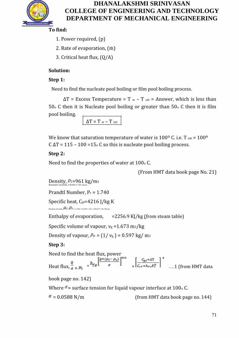
Need to find the properties of water at 100o C.
(From HMT data book page No. 21)
Density, =961 kg/m3 Kinematic viscosity, ν=0.293 ⨯ 10-6 m2/s
Prandtl Number, Pr = 1.740
Specific heat, Cpl=4216 J/kg K
Dynamic viscosity, = ⨯ ν =961 ⨯ 0.293 ⨯ 10-6 = 281.57⨯ 10-6 Ns/m2
Enthalpy of evaporation, =2256.9 KJ/kg (from steam table)
Specific volume of vapour, νg =1.673 m3/kg
Density of vapour, = (1/ νg ) = 0.597 kg/ m3
Step 3:
Need to find the heat flux, power
Heat flux,
=
⨯
⨯
…….1 (from HMT data
book page no. 142)
Where = surface tension for liquid vapour interface at 100o C.
= 0.0588 N/m (from HMT data book page no. 144)
71

DHANALAKSHMI SRINIVASAN
COLLEGE OF ENGINEERING AND TECHNOLOGY
DEPARTMENT OF MECHANICAL ENGINEERING
For water – copper = surface fluid constant = 0.013 and n=1 for
water (from HMT data book page no.143)
Substitute the , , , , ,n and Pr values in equation 1 = 4.83 ⨯ 105 W/m2
Heat transfer Q = 4.83 ⨯ 105 ⨯ A
Area A = d2 = 0.113 m2
Power = 54.7 kW
Step 4:
Need to find Rate of evaporation, (ṁ)
Heat transferred Q = ṁ ⨯
Substitute Q and
ṁ = 0.024
Step 5:
Need to find the critical flux
For nucleate pool boiling, critical heat flux, = 0.18 ⨯
(from HMT data book page no. 142)
Critical heat flux, q = =1.52 ⨯ 106 W/m2
3. A wire of 1 mm diameter and 150mm length is submerged
horizontally in water at 7 bar. The wire carries a current of 131.5
ampere with an applied voltage of 2.15 Volt. If the surface of the wire
is maintained at 180o C, calculate the heat flux and the boiling heat
transfer coefficient.(May/June 2014 Reg 2008)
Given:
Diameter, D = 1 mm =1 ⨯ 10-3 m; Length, L = 150mm = 150 ⨯ 10-3 m; Pressure, P = 7 bar
72

DHANALAKSHMI SRINIVASAN
COLLEGE OF ENGINEERING AND TECHNOLOGY
DEPARTMENT OF MECHANICAL ENGINEERING
Voltage, V = 2.15 V
Current, I = 131.5 amps
T w = 180o C
To find:
1. Heat flux,
2. Heat transfer coefficient, h
Solution:
Step 1:
Need to find heat flux Q = V ⨯ I = 2.15 ⨯ 131.5 = 282.72W A = πDL = π ⨯ 1 ⨯ 10-3 ⨯150 ⨯ 10-3 =471.23 ⨯ 10-6 m2 Heat flux = = 282.72/471.23 ⨯ 10-6 =599.950 ⨯ 103 W/m2
= 599.950 ⨯ 103 W/m2
Step 2:
Need to find the heat transfer co efficient h
At pressure P = 7 bar: ∆T = 180 – 100 =80o C
Heat transfer co efficient, h = 5.56 (∆T)3
(From HMT data book page no: 143)
h= 2846720 W/m2 K
Heat transfer coefficient other than atmospheric pressure hp = h P 0.4 =2846720 ⨯ 70.4 = 6.19⨯106 W/m2 K
hp = 6.19⨯106 W/m2 K
4. A vertical cooling fin approximating a flat plate 40 cm in height is
exposed to saturated steam at atmospheric pressure. The fin is
maintained at a temperature of 90o C. estimate the thickness of the
film at the bottom of the fin, overall heat transfer coefficient and heat
transfer rate after incorporating McAdam’s correction, the rate of
condensation of steam. (Nov/Dec 2015 Reg 2008)
73

DHANALAKSHMI SRINIVASAN
COLLEGE OF ENGINEERING AND TECHNOLOGY
DEPARTMENT OF MECHANICAL ENGINEERING
Given:
Height (or) Length, L = 40 cm = 0.4m
Surface temperature, Tw = 90o C
To find:
1. The film thickness δx
2. Overall heat transfer coefficient h (McAdam’s correction)
3. Heat transfer rate Q
4. Rate of condensation of steam ṁ
Solution:
Step 1:
We know that, saturation temperature of water is 100o C, i.e. T sat = 100o
C =2256.9 KJ/kg (from steam table)
We know that
Film temperature, Tf = = 95oC
Properties of saturated water at 95oC (from HMT data book page no: 21)
Density, =967.5 kg/m3 Kinematic viscosity, ν=0.328 ⨯ 10-6 m2/s
Specific heat, Cpl=4205.5 J/kg K
Thermal conductivity K =0.674 W/mk
Dynamic viscosity, = ⨯ ν =967.5 ⨯ 0.328⨯ 10-6 = 3.173⨯ 10-4 Ns/m2
Step 2:
We need to find the film thickness
δx = (from HMT data book page no: 148)
substitute all appropriate property value in above formula δx = 1.13 ⨯ 10-4 m
Step 3:
We need to find the heat transfer coefficient h
For vertical surface laminar flow (assume) or find by Re-Reynolds number
Re = here P = perimeter; Re > 1800 then that flow is turbulent flow,
Re < 1800 then that flow is laminar flow,
74

DHANALAKSHMI SRINIVASAN
COLLEGE OF ENGINEERING AND TECHNOLOGY
DEPARTMENT OF MECHANICAL ENGINEERING
h= 0.943 (from HMT data book page no: 148)
The factor 0.943 may be replaced by 1.13 for more accurate result
as suggested by Mc Adams
h= 1.13
Substitute all the properties in above formula
h= 1495.3 W/m2 K
Step 4:
We need to find the heat transfer rate Q
Q=h A = h L W Q= 1495.3 ⨯ 0.4 ⨯ 1⨯ 10 = 5981.26 W
Q = 5981.26 W
Step 5:
We need to find the rate of condensation of steam
ṁ Q = ṁ
ṁ = Q/
ṁ = 0.00265 kg/s
5. A condenser is to be designed to condense 600 kg/h of dry
saturated steam at a pressure of 0.12 bar. A square array of 400
tubes, each of 8 mm diameters is to be used. The tube surface is
maintained at 30o C. Calculate the heat transfer coefficient and the
length of each tube. (April/May 2015) (NOV/DEC 2013)
Given:
ṁ = 600 kg/h = 0.166 kg/s
Pressure P = 0.12 bar
No. of tubes = 400 Diameter, D = 8 mm = 8 ⨯ 10-3 m
Surface temperature, Tw = 30o C.
75

DHANALAKSHMI SRINIVASAN
COLLEGE OF ENGINEERING AND TECHNOLOGY
DEPARTMENT OF MECHANICAL ENGINEERING
To find:
1. Heat transfer coefficient h
2. Length
Solution:
Step 1:
We need find the properties of steam at 0.12
bar =49.45 o C.
(from steam table)
= 2384.3 103 J/kg
Film temperature, Tf = = 39.72oC =40 o C
Properties of saturated water at 40oC (from HMT data book page no: 21) Kinematic viscosity, ν=0.657 ⨯ 10-6 m2/s
Thermal conductivity K =0.628 W/mk
Dynamic viscosity, = ⨯ ν =995 ⨯ 0.657⨯ 10-6 = 653.7⨯ 10-6 Ns/m2 With 400 tubes, a 20 ⨯ 20 tube of square array could be formed
N = = 20
Step 2:
We need to find the heat transfer coefficient h
h= 0.728 (from HMT data book page no: 148)
h= 5304.75 W/m2 K
Step 3:
Q=h A = h D L =1.05 ⨯ 106 L -----1
We know that
Q = ṁ = 0.3957⨯ 106 W -----2
Equating (1) and (2) We get, L = 0.37
6. In a double pipe counter flow heat exchanger,10000 kg/hr of an oil
having a specific heat of 2095 J/kg-k is cooled from 80oc to 50oc by
800kg/hr of water entering at 25oc. Determine the heat exchanger area
76

DHANALAKSHMI SRINIVASAN
COLLEGE OF ENGINEERING AND TECHNOLOGY
DEPARTMENT OF MECHANICAL ENGINEERING
for an overall heat transfer co-efficient of 300 W/m2k.Take CP for water
as 4180 J/kg-k.
Given:
Hot fluid – oil (T1-T2) Cold fluid - water (t1-t2)
The mass flow rate of oil (Hot fluid),mh =10000
kg/hr =
mh = 2.277kg/s
Specific heat of oil, Cph = 2095 J/kg-k
Entry temperature of oil , T1 = 80OC
Exit temperature of oil , T2 = 50OC
Mass flow rate of water (Cold fluid),mc =8000
kg/hr =
mc = 2.22 kg/s
Entry temperature of water, t1 = 25OC
Overall heat transfer co-efficient, U = 300 W/m2k
Specific heat of water, Cpc = 4180 J/kg-k
To find:
Heat exchanger area, A
Solution:
Heat lost by oil (Hot fluid) = Heat gained by water (Cold fluid)
Qh = Qc
mh Cph (T1-T2) = mc Cpc (t1-t2)
2.277 x 2095 (80-50) = 2.22 x 4180 x (t2 – 25)
174.53 x 103 = 9.27 x 10³ t2 -231.99 x 10³
t2 = 43.85oc
Exit temperature of water, t2 = 43.85oc
Heat transfer,Q = mh Cph (T1-T2) or mc Cpc (t1-t2)
77
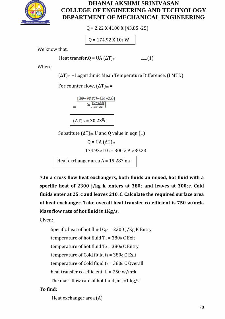
DHANALAKSHMI SRINIVASAN
COLLEGE OF ENGINEERING AND TECHNOLOGY
DEPARTMENT OF MECHANICAL ENGINEERING
Q = 2.22 X 4180 X (43.85 -25)
Q = 174.92 X 10³ W
We know that,
Heat transfer,Q = UA (∆T)m ......(1)
Where,
(∆T)m – Logarithmic Mean Temperature Difference. (LMTD)
For counter flow, (∆T)m =
=
(∆T)m = 30.230c
Substitute (∆T)m, U and Q value in eqn (1)
Q = UA (∆T)m
174.92×103 = 300 × A ×30.23
Heat exchanger area A = 19.287 m2
7.In a cross flow heat exchangers, both fluids an mixed, hot fluid with a
specific heat of 2300 j/kg k ,enters at 3800 and leaves at 3000c. Cold
fluids enter at 250c and leaves 2100C. Calculate the required surface area
of heat exchanger. Take overall heat transfer co-efficient is 750 w/m2k.
Mass flow rate of hot fluid is 1Kg/s.
Given:
Specific heat of hot fluid Cph = 2300 J/Kg K Entry
temperature of hot fluid T1 = 380O C Exit
temperature of hot fluid T2 = 380O C Entry
temperature of Cold fluid t1 = 380O C Exit
temperature of Cold fluid t2 = 380O C Overall
heat transfer co-efficient, U = 750 w/m2k
The mass flow rate of hot fluid ,mh =1 kg/s
To find:
Heat exchanger area (A)
78

DHANALAKSHMI SRINIVASAN
COLLEGE OF ENGINEERING AND TECHNOLOGY
DEPARTMENT OF MECHANICAL ENGINEERING
Solution:
This is Cross flow, both fluids unmixed type heat exchanger.
For cross flow heat exchanger,
Q = F UA (∆T)m (counter flow) ......(1)
[From HMT Data book page No.152]
Where,
(∆T)m – Logarithmic Mean Temperature Difference for counter
flow. For counter flow, (∆T)m =
=
(∆T)m = 218.30c
Heat transfer,Q = mh Cph (T1-T2)
Q = 1 X 2300 X (380-300)
Q = 184 X 103 W
To find correction factor F, refer HMT data book page No 162
[Single pass cross flow heat exchanger – Both fluids unmixed]
From graph,
Xaxis value P =
= X axis Value is 0.52, Curve Value is 0.432,
corresponding Yaxis Value is 0.97 i,e F= 0.97
P = 0.52
Curve Value R =
=
R = 0.432
79
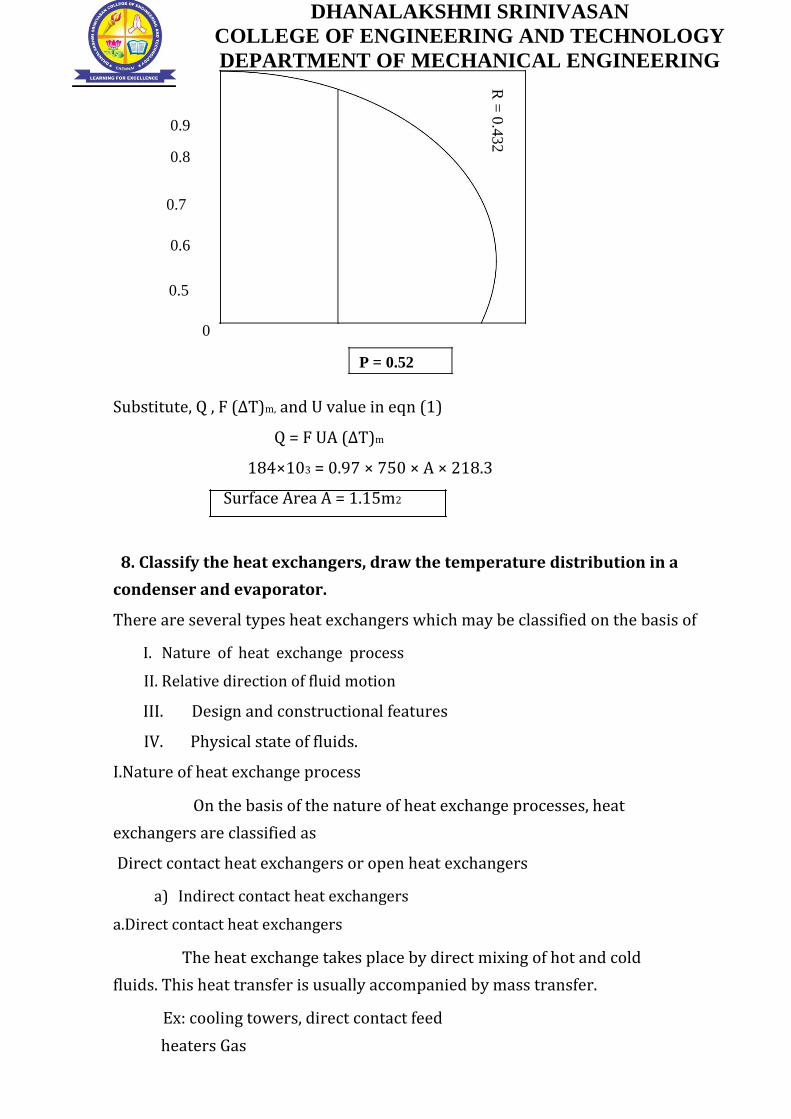
DHANALAKSHMI SRINIVASAN
COLLEGE OF ENGINEERING AND TECHNOLOGY
DEPARTMENT OF MECHANICAL ENGINEERING
0.9
0.8
0.7
0.6
0.5
0
R =
0.4
32
P = 0.52
Substitute, Q , F (∆T)m, and U value in eqn (1)
Q = F UA (∆T)m
184×103 = 0.97 × 750 × A × 218.3
Surface Area A = 1.15m2
8. Classify the heat exchangers, draw the temperature distribution in a
condenser and evaporator.
There are several types heat exchangers which may be classified on the basis of
I. Nature of heat exchange process
II. Relative direction of fluid motion
III. Design and constructional features
IV. Physical state of fluids.
I.Nature of heat exchange process
On the basis of the nature of heat exchange processes, heat
exchangers are classified as
Direct contact heat exchangers or open heat exchangers
a) Indirect contact heat exchangers
a.Direct contact heat exchangers
The heat exchange takes place by direct mixing of hot and cold
fluids. This heat transfer is usually accompanied by mass transfer.
Ex: cooling towers, direct contact feed
heaters Gas

DHANALAKSHMI SRINIVASAN
COLLEGE OF ENGINEERING AND TECHNOLOGY
DEPARTMENT OF MECHANICAL ENGINEERING
80

DHANALAKSHMI SRINIVASAN
COLLEGE OF ENGINEERING AND TECHNOLOGY
DEPARTMENT OF MECHANICAL ENGINEERING
Hot Water
Steam
Cold Water
b. Indirect contact heat exchangerscould be carried out by transmission through
a wall which separates the two fluids
It may be classified as
i)Regenerators
ii)Recuperators
Regenerators
Hot and cold fluids flow alternately through the same space
Ex: IC engines, gas turbines
Recuperators
This is most common type of heat exchanger in which the hot and cold fluid
do not come into direct contact with each other but are seperated by atube
wall or a surface.
Ex: Automobile radiators, Air pre
heaters,Economisers Advantages
1.Easy construction
2. More economical
3. More surface area for heat transfer
Disadvantages
81

DHANALAKSHMI SRINIVASAN
COLLEGE OF ENGINEERING AND TECHNOLOGY
DEPARTMENT OF MECHANICAL ENGINEERING
1.Less heat transfer co-efficient
2.Less generating capacity
II.Relative direction of fluid motion
a.Parallel flow heat exchanger
b.Counter flow heat exchanger
c.Cross flow heat exchanger
a)Parallel Flow – the hot and cold fluids flow in the same direction. Depicts such a
heat exchanger where one fluid (say hot) flows through the pipe and the other
fluid (cold) flows through the annulus.
(b) Counter Flow – the two fluids flow through the pipe but in opposite
directions. A common type of such a heat exchanger. By comparing the
temperature distribution of the two types of heat exchanger
We find that the temperature difference between the two fluids is more
uniform in counter flow than in the parallel flow. Counter flow exchangers give
the maximum heat transfer rate and are the most favoured devices for heating or
cooling of fluids. When the two fluids flow through the heat exchanger only once,
it is called one-shell-pass and one-tube-pass
82

DHANALAKSHMI SRINIVASAN
COLLEGE OF ENGINEERING AND TECHNOLOGY
DEPARTMENT OF MECHANICAL ENGINEERING
(c) Cross-flow - A cross-flow heat exchanger has the two fluid streams flowing at
right angles to each other. illustrates such an arrangement An automobile
radiator is a good example of cross-flow exchanger. These exchangers are 'mixed'
or 'unmixed' depending upon the mixing or not mixing of either fluid in the
direction transverse to the direction of the flow stream and the analysis of this
type of heat exchanger is extremely complex because of the variation in the
temperature of the fluid in and normal to the direction of flow
.
III.Design and constructional features
a.Concentric tubes
b.Shell and tube
c.Multible shell and tube passes
d.Compact heat exchangers
a Concentric tubes
Two concentric pipes ,each carrying one of the fluids are used as a heat
exchanger.The direction of flow may be parallel or counter.
b. Shell and tube
One of the fluids move through a bundle of tubes enclosed by a shell.The
other fluid is forced through the shell and it moves over the outside surface of the
tubes.
83

DHANALAKSHMI SRINIVASAN
COLLEGE OF ENGINEERING AND TECHNOLOGY
DEPARTMENT OF MECHANICAL ENGINEERING
c. Multible shell and tube passes
If the fluid flowing through the tube makes one pass through half of the
tube, reverses its direction of flow, and makes a second pass through the
remaining half of the tube, it is called 'one-shell-pass, two-tube-pass' heat
exchanger, Many other possible flow arrangements exist and are being used.
depicts a 'two-shell-pass, four-tube-pass' exchanger. d.Compact heat exchangers
There are many special purpose heat exchangers called compact heat
exchangers.They are generally employed when convective heat transferco-
efficient associated with one of the fluids is much smaller than that associated
with the other fluid.
IV.Physical state of fluids
a.Condensers
b.Evaporators
a)Condenser
In a condenser, the condensing fluid temperature remains almost constant
throughout the exchanger and temperature of the colder fluid gradually increases
from the inlet to the exit.
84
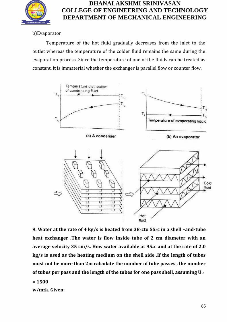
DHANALAKSHMI SRINIVASAN
COLLEGE OF ENGINEERING AND TECHNOLOGY
DEPARTMENT OF MECHANICAL ENGINEERING
b)Evaporator
Temperature of the hot fluid gradually decreases from the inlet to the
outlet whereas the temperature of the colder fluid remains the same during the
evaporation process. Since the temperature of one of the fluids can be treated as
constant, it is immaterial whether the exchanger is parallel flow or counter flow.
9. Water at the rate of 4 kg/s is heated from 38octo 55oc in a shell –and-tube
heat exchanger .The water is flow inside tube of 2 cm diameter with an
average velocity 35 cm/s. How water available at 95oc and at the rate of 2.0
kg/s is used as the heating medium on the shell side .If the length of tubes
must not be more than 2m calculate the number of tube passes , the number
of tubes per pass and the length of the tubes for one pass shell, assuming UO
= 1500
w/m2k. Given:
85

DHANALAKSHMI SRINIVASAN
COLLEGE OF ENGINEERING AND TECHNOLOGY
DEPARTMENT OF MECHANICAL ENGINEERING
Mc = 4 kg/s
TCI =38O C
TCO = 55OC
U = 35m/s
Thi = 95oc
Ch = 2 kg/s
UO = 1500 w/m2k
To find:
1) Number of tubes per pass
2) Number of passes
3) Length of tube per pass
Solution:
The heat transfer rate for the cold fluid is
Q = mc cc
= 4 X 4186 (55-38)
Q = mhChΔTh
= 284.65 kw
ΔTh =
= 34OC
Tho = 95-34 =61oc
Counter flow heat exchanger
ΔTln =
ΔT1 = Th, I – Tc, o
= 95-55 = 40oc
ΔT2 = Th, o – Tc, i
= 61-38 = 23oc
ΔTln = = 30.72oc
86

DHANALAKSHMI SRINIVASAN
COLLEGE OF ENGINEERING AND TECHNOLOGY
DEPARTMENT OF MECHANICAL ENGINEERING
A= = 284.65 X 1000 /((1500)X30.72)
= 6.177m2
Using average velocity of water in the tubes and its flow
rates mc = ρAU
A = 4/[(1000)(0.35)]
A = 0.011429m2
This area is can also be put as the number of
tubes 0.011429=nπ
n = 36.38
Taking n = 36, the total surface area of tubes for one shell pass exchanger
in terms of L,
A = 6.177 =nπdL
L =6.177/[(36)π(0.02)]
L= 2.731m
Since this length is grater than the permitted length of 2m,
P =
= 0.3
R =
R = 2
Thus the total area required for one shall pass,2 tube pass exchanger is
A’ = Q /[UFΔTln]
A’ = 6.863m2
Due to velocity requirement let the number of tubes pr pass still be
36 A’ = 2nπdl
L = 6.863/[2 X 36 X π X0.02]
L = 1.517 m
87

DHANALAKSHMI SRINIVASAN
COLLEGE OF ENGINEERING AND TECHNOLOGY
DEPARTMENT OF MECHANICAL ENGINEERING
PART C - 15 Marks (Questions and Answers)
1. A nickel wire carrying electric current of 1.5 mm diameter and 50 cm
long, is submerged in a water bath which is open to atmospheric
pressure.calculate the voltage at the burn out point, if at this point the wire
carries a current of 200A.
Given:
D = 1.5 mm = 1.5 *103 m
L =50 cm = 0.50 m
Current , I = 200 A.
To find:
Voltage (v)
Solution:
We know that, saturation temperature of water is 100o C.
i.e., Tsat = 100o C.
PROPERTIES OF WATER AT 100O c .
From HMT Data book page no 21
ρl = 961 Kg / m3
ν = 0.293 * 10-6 m2/s
Pr = 1.740
Cpl = 4216 J /Kg k
μl = ρl * ν
= 961 * 0.293 * 10-6
= 281.57 * 10-6 Ns/ m2
From steam table at 100O c .
hfg = 2256.9 KJ/Kg
hfg = 2256.9 * 10 3 J/Kg
νg = 1.673 m3/Kg
ρ ν = 1/ νg = 1/ 1.673
= 0.597 Kg / m3
ς = surface tension for liquid – vapour interface
At 100o C ( From HMT databook page no 144)
ς = 0.0588 N/m
88

DHANALAKSHMI SRINIVASAN
COLLEGE OF ENGINEERING AND TECHNOLOGY
DEPARTMENT OF MECHANICAL ENGINEERING
For Nucleate pool boiling critical heat flux ( at burn out)
Q/A = 0.18 * hfg * ρ ν [ ((ς * g * (ρl - ρ ν )) /( ρ ν 2 ))]0.25
From HMT databook page no 142
Substitute hfg , ρl ,ς , ρv
Q/A = 0.18 * 2256.9 * 103 * 0.597 8 [ (( 0.0588 * 9.81 * ( 961 – 0.597 )) /
(0.597)2)]
Q/A = 1.52 * 106 W/m2.
Heat transferred , Q = V * 1
Q/A = (V*1) / A
1.52 * 106 = (V * 200)/ (πdL)
1.52 * 106 = ((V *200) / (π * 1.5 *10-3 * 0.50 ))
V = 17.9 Volts
2. An oil cooler of the form of tubular heat exchanger cools oil from a
temperature of 90o C to 35o C by a large pool of stagnant water assumed at
constant temperature of 28o .The tube length is 32 m and diameter is 28
mm. The specific heat and specific gravity of the oil are 2.45 KJ / Kg K and
0.8 respectively. The velocity of the oil is 62 cm / s. Calculate the overall
heat transfer co – efficient.
Given:
Hot fluid – oil Cold fluid - water
( T1, T2) (t1 , t2)
Entry temperature of oil T1 = 90O C
Exit temperature of oil T2 = 35o C
Entry and Exit temperature of water , t1 = t2 = 28o C
Tube length L = 32 m
Diameter D = 28 mm = 0.028 m
Specific heat of oil , Cph = 2.45 KJ/Kg k = 2.45 * 10 3 J/Kg k
Specific gravity of oil = 0.8
Velocity of oil, C =62 cm / s = 0.62 m/s.
89

DHANALAKSHMI SRINIVASAN
COLLEGE OF ENGINEERING AND TECHNOLOGY
DEPARTMENT OF MECHANICAL ENGINEERING
To Find:
Overall heat transfer co- efficient U
Solution:
Specific gravity of oil = Density of oil / density of water
= ρ0 / ρw
0.8 = ρ0 / 1000
ρ0 = 800 Kg / m3.
Mass flow rate of oil, mh = ρ0 * A *C
= 800 * ((π/4)*(D2)*0.62
= 800 * ((π/4)*(0.0282)*0.62
mh = 0.305 Kg / s.
Heat transfer , Q = mh * Cph * ( T1 – T2)
= 0.305 * 2.45 * 103 * (90 – 35)
Q = 41 * 103 W.
We know that
Heat transfer , Q = UA (∆T)m
From HMT databook page no 151
(∆T)m = logarithmic mean temperature difference ( LMTD)
For parallel flow
(∆T)m = [((T1 – t1) – (T2- t2))] / ln [ ((T1 – t1 ) /(T2 –t2 ))]
= [((90 – 28) – (35- 28))] / ln [ ((90 – 28 ) /(35 –28 ))]
(∆T)m = 25.2o C.
Substitute (∆T)m value in Q Equation
Q = UA (∆T)m
41*103 = U * π *D* L *(∆T)m
41*103 = U * π *0.028* 32 *25.2
U = 577.9
Overall heat transfer co – efficient , U = 577.9 W / m2 K
90

DHANALAKSHMI SRINIVASAN
COLLEGE OF ENGINEERING AND TECHNOLOGY
DEPARTMENT OF MECHANICAL ENGINEERING
UNIT: IV RADIATION
PART A - 2 Marks (Questions and Answers)
1. State Planck’s distribution law. (Nov/Dec 2013)
The relationship between the monochromatic emissive power of a
black body and wave length of a radiation at a particular temperature is
given by the following expression, by Planck.
Eb C
1
5
C2
e T
1
Where
c1 = 0.374 10-15 W m2
c2 = 14.4 10-3 mK
2. State Wien’s displacement law & Stefan – Boltzmann law. (Nov/Dec 2010)
The Wien’s law gives the relationship between temperature and
wave length corresponding to the maximum spectral emissive power of the
black body at that temperature.
max T 2.9 10 3 mK
The emissive power of a black body is proportional to the fourth
power of absolute temperature.
Eb = T4
Where = Stefan – Boltzmann constant
= 5.67 10-8 W/m2K4
Eb = (5.67 10-8) (2773)4
Eb = 3.35 106 W/m2
3. State Kirchoff’s law of radiation. (April/May 2015)
This law states that the ratio of total emissive power to the
absorptivity is constant for all surfaces which are in thermal equilibrium
with the surroundings. This can be written as
E1 = E2 = E3 ............
1 2 3
91

DHANALAKSHMI SRINIVASAN
COLLEGE OF ENGINEERING AND TECHNOLOGY
DEPARTMENT OF MECHANICAL ENGINEERING
It also states that the emissivity of the body is always equal to its
absorptivity when the body remains in thermal equilibrium with its
surroundings.
α1 = E 1; α2 = E2 and soon.
4. What is the purpose of radiation shield? (Nov/Dec 2014)
Radiation shields constructed from low emissivity (high reflective)
materials. It is used to reduce the net radiation transfer between two
surfaces.
5. Define irradiation (G) and radiosity (J) (Nov/Dec 2015)
It is defined as the total radiation incident upon a surface per unit
time per unit area. It is expressed in W/m2.
It is used to indicate the total radiation leaving a surface per unit
time per unit area. It is expressed in W/m2.
6. What are the factors involved in radiation by a body. (Nov /Dec 2014)
Wave length or frequency of radiation
The temperature of surface
The nature of the surface
7. What is meant by shape factor?
The shape factor is defined as the fraction of the radiative energy that is
diffused from on surface element and strikes the other surface directly with no
intervening reflections. It is represented by Fig. Other names for radiation shape
factor are view factor, angle factor and configuration factor.
8. How radiation from gases differs from solids? (Nov/Dec 2013)
A participating medium emits and absorbs radiation throughout its entire
volume thus gaseous radiation is a volumetric phenomenon, solid radiation is a
surface phenomena Gases emit and absorb radiation at a number of narrow
wavelength bands. This is in contrast to solids, which emit and absorb radiation
over the entire spectrum.
92

DHANALAKSHMI SRINIVASAN
COLLEGE OF ENGINEERING AND TECHNOLOGY
DEPARTMENT OF MECHANICAL ENGINEERING
9. What is black body and gray body?
Black body is an ideal surface having the following properties. A black
body absorbs all incident radiation, regardless of wave length and direction. For a
prescribed temperature and wave length, no surface can emit more energy than
black body. If a body absorbs a definite percentage of incident radiation
irrespective of their wave length, the body is known as gray body. The emissive
power of a gray body is always less than that of the black body.
10. Define emissive power [E] and monochromatic emissive power. [Ebλ]
The emissive power is defined as the total amount of radiation emitted by
a body per unit time and unit area. It is expressed in W/m2.
The energy emitted by the surface at a given length per unit time per unit
area in all directions is known as monochromatic emissive power.
11. Two parallel radiating Planes 10 x 50 cm are separated by a distance Of
50 cm .what is the radiation shape factor between the planes?(May/June
2012)
L=100 cm B= 50 cm D= 50 cm [From HMT data book ,Page no.92]
X=L/D=100/50=2 Y=B/D = 50/50=1
From table,for X=2 and Y=1
F12=F21=0.28588
12. What does the view factor represent? When is the view factor from a
surface to itself not zero?
The view factor Fi-j represents the fraction of the radiation leaving surface
i that strikes surface j directly. The view factor from a surface to itself is non-zero
for concave surfaces.
13. State Lambert’s cosine law.
It states that the total emissive power Eb from a radiating plane surface in
any direction proportional to the cosine of the angle of emission
Eb cos
93

DHANALAKSHMI SRINIVASAN
COLLEGE OF ENGINEERING AND TECHNOLOGY
DEPARTMENT OF MECHANICAL ENGINEERING
14. Find the temperature of the sun assuming as a Block Body, if the
intensity of radiation is maximum at the wavelength of 0.5µ
According to Wien’s displacement law:
max T= 2.9 10-3 mK
0.5 10-6 T = 2.9 10-3
T= 5800 K
15. What is a radiation shield? Why is it used?
Radiation heat transfer between two surfaces can be reduced greatly by
inserting a thin, high reflectivity (low emissivity) sheet of material between the
two surfaces. Such highly reflective thin plates or shells are known as radiation
shields. Multilayer radiation shields constructed of about 20 shields per cm.
thickness separated by evacuated space are commonly used in cryogenic and
space applications to minimize heat transfer. Radiation shields are also used in
temperature measurements of fluids to reduce the error caused by the radiation
effect.
16. State Lamberts cosine law for radiation (April/May 2017)
It states that the total emissive power Eb from a radiating plane surface in any
direction proportional to the cosine of the angle of emission. Eb cos
17. Define monochromatic emissive power (Nov/Dec 2016)
The monochromatic emissive power Eλ, is defined as the rate, per unit area,
at which the surface emits thermal radiation at a particular wavelength λ. Thus the
total and monochromatic hemispherical emissive power are related by
18. What is meant by infrared and ultra violet radiation (Nov/Dec 2016)
Infrared radiation, or simply infrared or IR, is electromagnetic radiation
(EMR) with longer wavelengths than those of visible light, and is therefore
invisible Ultraviolet (UV) radiation is a type of radiation that is produced by
the sun and some artificial sources, such as solariums
94

DHANALAKSHMI SRINIVASAN
COLLEGE OF ENGINEERING AND TECHNOLOGY
DEPARTMENT OF MECHANICAL ENGINEERING
PART B - 13 Marks (Questions and Answers)
1. Calculate the following for an industrial furnace in the form of a black
body and emitting radiation at 25000C
Monochromatic emissive power at 1.2 m wave length.
i) Wave length at which emission is maximum.
ii) Maximum emissive power.
iii) Total emissive power,
iv) The total emissive of the furnace if it is assumed as a real surface
having emissivity equal to 0.9. (Nov / Dec 2014) (Nov / Dec 2015)
Given: Surface temperature T = 25000C=2773K
Monochromatic emissive power = 1.2 10-6 m
Emissivity = 0.9
Solution:
Step 1. Monochromatic Emissive Power:
From Planck’s distribution law, we know
Eb
C 5
1
C2 [From HMT data book, Page No.82]
e T 1
Where
c1 = 0.374 10-15 W m2
c2 = 14.4 10-3 mK
= 1.2 10-6 m [Given]
Ebλ=5.39x10¹²
Step 2. Maximum wave length (max)
From Wien’s law, we know
max T 2.9 10 3 mK
max 2773 2.9 10 3 mK
max=5.37 10-16
Step 3. Maximum emissive power (Eb) max:
95

DHANALAKSHMI SRINIVASAN
COLLEGE OF ENGINEERING AND TECHNOLOGY
DEPARTMENT OF MECHANICAL ENGINEERING
Maximum emissive power
(Eb) max = 1.307 10-5 T5
= 1.307 10-5 (2773)5
(Eb) max = 2.14 1012 W/m2
Step 4. Total emissive power (Eb):
From Stefan – Boltzmann law, we know that
Eb = T4 [From HMT data book Page No.72] Where = Stefan –
Boltzmann constant
= 5.67 10-8 W/m2K4
Eb = (5.67 10-8) (2773)4
Eb = 3.35 106 W/m2
Step 5. Total emissive power of a real surface:
(Eb) real = T4
Where = Emissivity = 0.9
(Eb) real = 0.9x5.67x10-8(2773)4
(Eb) real =3.01106 W/m2
2.Two parallel plates of size 1.0 m x 1.0 m spaced 0.5 m aprat are ;ocated in
very large room , the walls are maintained at a temperature of 270C .one
plate is maintained at a temperature of 9000C and other at 4000C .their
emissivities are 0.2 and 0.5 respectively .if the plate exchange heat
themselves and surroundings , find the heat transfer to each plate and to
them . consider only the plate surface facing each other.(May/June
2012&Nov/Dec 2014)
Given:
Size of the Plate = 1.0 m x 1.0 m
Distance between plates = 0.5 m
Room Temperature ,T3 = 270C + 273 = 300 K First
plate temperature , T1=9000C + 273 = 1173 K
96

DHANALAKSHMI SRINIVASAN
COLLEGE OF ENGINEERING AND TECHNOLOGY
DEPARTMENT OF MECHANICAL ENGINEERING
Second plate temperature , T2=4000C + 273 =673 K
Emissivity of first plate,ɛ1 = 0.2
Emissivity of second plate,ɛ2 = 0.5
To Find:
1. Net Heat Transfer to each
2. Net heat transfer to room
Solution:
In this problem heat exchange take place between two plates and the room
.so, this is three surface problem and the corresponding radiation network is
given below.
Electrical network diagram
Area ,A1 = 1 x 1= 1 m2
A1 = A2 = 1 m2
Since the room is large ,A3 = ∞
Step:1 From electrical network diagram,
1 1
1 0.2 4
A 1
1 0.2
1
1 2
1 0.5 1
A 2
1 0.5
2
1 3 0
[ A3=∞]
A 3
3
Apply 1 1
4 , 1 2 1,
1 3 0 values in electrical network diagram.
A 1
A 2
A 3
1 2 3
97

DHANALAKSHMI SRINIVASAN
COLLEGE OF ENGINEERING AND TECHNOLOGY
DEPARTMENT OF MECHANICAL ENGINEERING
Electrical network diagram
Step:2 To find shape factor F12,refer HMT data book page no.92 and 93
X= DL
01
.5 2
Y= DB
01
.5 2
X value is 2,Y value is 2 .From that ,we can find corresponding shape factor
value is 0.41525
i.e F12 =0.41525
we know that ,
F11+ F12+ F13 =1 , we know that F11= 0
F13 = 1-0.41525
F13 = 0.5847
Similarly, F21+ F22+ F23 =1 We Know that, F22 = 0
[From the table]
F23 = 1- F21
= 1 - F12 =1- 0.41525
= 0.5847
From electrical network diagram,
1 1 1.7102
1 0.5847
A F
1 13
98
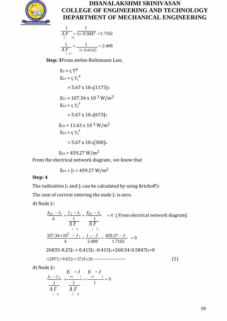
DHANALAKSHMI SRINIVASAN
COLLEGE OF ENGINEERING AND TECHNOLOGY
DEPARTMENT OF MECHANICAL ENGINEERING
1
1
1.7102
A F 1 0.5847
2 23
1 1 2.408 A F
1 0.41525
1 12
Step: 3From stefan-Boltzmann Law,
Eb = ς T4
Eb1 = ς T14
= 5.67 x 10⁻⁸[1173]4
Eb1 = 107.34 x 10 3 W/m2
Eb2 = ς T24
= 5.67 x 10⁻⁸[673]4
Eb2 = 11.63 x 10 3 W/m2
Eb3 = ς T34
= 5.67 x 10⁻⁸[300]4
Eb3 = 459.27 W/m2
From the electrical network diagram , we know that
Eb3 = J3 = 459.27 W/m2
Step: 4
The radiosities J1 and J2 can be calculated by using Krichoff’s
The sum of current entering the node J1 is zero.
At Node J1:
Eb1 J1
J 2 J1
Eb3 J1 0 [ From electrical network diagram]
4
1
1
A
1
F12
A1
F13
107.34 103 J 1
J 2 J 1 459.27 J 1 0
4
2.408
1.7102
26835-0.25J1 + 0.415J2 -0.415J1+268.54-0.5847J1=0
-1.2497 J1 + 0.415 J2 = -27.10 x 10³ ------------------------------ (1)
At Node J2:
J1 J 2
Eb3
J1
E
b2
J 2 0
1
1
1
A
1
F12
A2
F23
99

DHANALAKSHMI SRINIVASAN
COLLEGE OF ENGINEERING AND TECHNOLOGY
DEPARTMENT OF MECHANICAL ENGINEERING
J 2 J 1 459.27 J 1
11.63 10 3 0
2.408 1.7102
1
0.415 J1 -1.4997 J2 = -11.898 x 10³ ------------------------------(2)
Solving the equation (1) and (2)
-1.2497 J1 + 0.415 J2 = -27.10 x 10³
-0.415 J1 -1.4997 J2 = -11.898 x 10³
J1 = 26.780 x 10³ W/m2
J2 = 15.34 x 10³ W/m2
Step: 5
Heat lost by plate (1) Q1 =
Eb1 J1
[ From electrical network diagram]
1 1
A11
= 107.34 103 26.780 10
3
1 0.2 1 0.2
Q1=20.140 x 10³ W
Heat lost by plate (1) Q2 = J
2
E
b 2
1 2
A2 2
= 15.34 103 11.63 10
3
1 0.5 1 0.5
Q2 = 3710 W
Total heat lost by the plates(1) and(2)
Q = Q1+Q2
Q = 20.140 x 10³+3710
Q =23.850 x 10³ W
Total heat received or absorbed by the room
Q = J1 J 3 J 2 J 3
1
1
A
1
F13
A2
F23
100
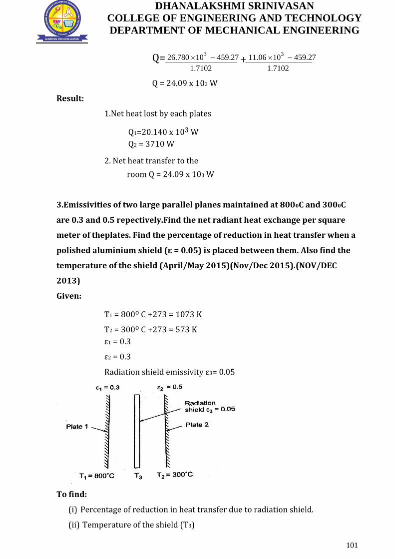
DHANALAKSHMI SRINIVASAN
COLLEGE OF ENGINEERING AND TECHNOLOGY
DEPARTMENT OF MECHANICAL ENGINEERING
Q= 26.780 103 459.27 11.06 10
3 459.27
1.7102 1.7102
Q = 24.09 x 10³ W
Result:
1.Net heat lost by each plates
Q1=20.140 x 10³ W
Q2 = 3710 W
2. Net heat transfer to the
room Q = 24.09 x 10³ W
3.Emissivities of two large parallel planes maintained at 8000C and 3000C
are 0.3 and 0.5 repectively.Find the net radiant heat exchange per square
meter of theplates. Find the percentage of reduction in heat transfer when a
polished aluminium shield (ɛ = 0.05) is placed between them. Also find the
temperature of the shield (April/May 2015)(Nov/Dec 2015).(NOV/DEC
2013)
Given:
T1 = 800o C +273 = 1073 K
T2 = 300o C +273 = 573 K
ε1 = 0.3
ε2 = 0.3
Radiation shield emissivity ε3= 0.05
To find:
(i) Percentage of reduction in heat transfer due to radiation shield.
(ii) Temperature of the shield (T3)
101

DHANALAKSHMI SRINIVASAN
COLLEGE OF ENGINEERING AND TECHNOLOGY
DEPARTMENT OF MECHANICAL ENGINEERING
Solution:
Case: 1 Heat transfer without radiation shield:
Heat exchange between two large parallel plates without radiation shield is
given by
Step: 1 Q12= A[T14 T2
4 ]
1
Where =
1 1 1
1 2
= 1 1
1 1
0.3 0.5
= 0.2307
Q12 = 0.2307 x 5.67 x 10-8 x A x [(1073)4-(573)4]
Step: 2
Q1 2 = 15.9 x 10³ W/m2
A
Heat transfer without radiation shield Q
1 2 = 15.9 x 10³ W/m2 ------------ (1)
Case : 2 Heat transfer with radition shield:
Heat exchange between radiation plate 1 and radiation shield 3 is
given Step: 3
Q13= A[T14 T3
4 ]
Where
=
1
1 1 1
1
3
A[T 4 T 4 ]
Q13 = 1 3 ------------ (2)
1
1 1
1 3
Heat exchange between radiation shield 3 and plate 2 is
given Step: 4
Q32= A[T34 T2
4 ]
102

DHANALAKSHMI SRINIVASAN
COLLEGE OF ENGINEERING AND TECHNOLOGY
DEPARTMENT OF MECHANICAL ENGINEERING
1
Where
=
1 1 1
3 2
A[T 4 T
4 ]
Q32 = 3 2 ------------ (3)
1
1
1
2
3
Step: 5
We know that,
Q13 = Q32
A[T 4 T 4 ] A[T 4 T
4 ]
1 3 = 3 2
1
1 1
1
1 1
2
1
3
3
A[10734 T
4 ] A[T
4 573
4 ]
3 = 3
1
1
1
1
1 1
0.3
0.05
0.5
0.05
3.02 x 10 13 = 43.3 T34
T3 = 913.8 K
Temperature of the shield T3 = 913.8 K
Substitute T3 value in equation (2) or (3),
Heat transfer with radiation shield Q13 = A[1073
4
913.8
4 ] 1
1
1 0.3 0.05
Q1 3 =159.46 W/m2
A
Step: 6
Percentage of reduction in heat transfer due to radiation shield
= Q
withoutshield
Q
withshield
Qwithshield
=
Q12
Q13
Q
12
= 15.8 103 1594.6 x 100
15.8 103
= 0.899 x 100 % = 89.9%
Percentage of reduction in heat transfer due to radiation shield= 89.9%
103

DHANALAKSHMI SRINIVASAN
COLLEGE OF ENGINEERING AND TECHNOLOGY
DEPARTMENT OF MECHANICAL ENGINEERING
4. The area A1 and A2 are perpendicular but do not share the common edge
.find the shape factor F1-2 for the arrangement. (Nov/Dec 2015).
Given:
To find : Shape Factor of F1-2
Solution:
From the figure we know that
Step: 1
A5 = A1 + A3
A6 = A2 + A4
Further Step: 2
A5 F5-6 = A1 F1-6 +A3 F3-6 [A5 = A1+ A3, F5-6=F1-6 + F3-6]
104

DHANALAKSHMI SRINIVASAN
COLLEGE OF ENGINEERING AND TECHNOLOGY
DEPARTMENT OF MECHANICAL ENGINEERING
= A1 F1-2 + A1 F1-4+A3 F3-6 [F1-6 = F1-2 + F1-4]
A5 F5-6 = A1 F1-2 + A5F5-4-A3F3-4+A3 F3-6 [A1 = A5-A3, F1-4=F5-4-F3-4]
A1F1-2 = A5 F5-6 - A5 F5-4 + A3 F3-4- A3 F3-6
F1-2 = A5 [ F5-6 - F5-4]+
A3 [ F3-4- F3-6] ----------------------------------- (1)
A A
1 1
[Refer HMT data book, Page no.95]
Z = L
B2 , Y=
LB
1
Step: 3
Shape Factor for the area A5 and A6
Z = L
B2 = 1
2 = 2
Y= L
B1 = 1
2 =2
Z value is 2, Y value is 2 .From that, we can find Corresponding shape factor
value is 0.14930
F5-6 = 0.14930
105

DHANALAKSHMI SRINIVASAN
COLLEGE OF ENGINEERING AND TECHNOLOGY
DEPARTMENT OF MECHANICAL ENGINEERING
Shape Factor for the area A5 and A4
Z = L
B2 =
11 = 1
Y= L
B1 = 1
2 =2
Z value is 1, Y value is 2 .From that, we can find Corresponding shape factor
value is 0.11643
F5-4 = 0.11643
Shape Factor for the area A3 and 4
Z = L
B2 =
11 = 1
Y= L
B1 =
11 =1
Z value is 1, Y value is 1 .From that, we can find Corresponding shape factor
value is 0.2004
F3-4 = 0.2004
106

DHANALAKSHMI SRINIVASAN
COLLEGE OF ENGINEERING AND TECHNOLOGY
DEPARTMENT OF MECHANICAL ENGINEERING
Shape Factor for the area A3 and A6:
Z = L
B2 = 1
2 = 2
Y= L
B1 =
11 =1
Z value is 2, Y value is 1 .From that, we can find Corresponding shape factor
value is 0.23285
F3-6 = 0.23285
Step: 4
Substitute F3-6 , F3-4 , F5-4 and F5-6 in equation (1)
F1-2 = A
5 [ F5-6 - F5-4]+
A3 [ F3-4- F3-6]
A
A
1 1
A5= 2 ; A3=A1=1
F1-2 = 2 [0.14930-0.11643] +
1 [0.2004-0.23285]
1
1
F1-2 =0.03293
F1-2 =0.03293
5. (a) State and Prove Kirchhoff’s law of thermal radiation.
This law states that the ratio of total emissive power to the aborptivity is
constant for all surfaces which are in thermal equilibrium with the surroundings.
E1 = E2 = E
3 ............
1 2 3
It also states that the emissivity of the body is always equal to its absorptivity hen
the body remains in thermal equilibrium with its surroundings.
α1 = E 1; α2 = E2 and soon.
107

DHANALAKSHMI SRINIVASAN
COLLEGE OF ENGINEERING AND TECHNOLOGY
DEPARTMENT OF MECHANICAL ENGINEERING
(b) What is a black body? A20 cm diameter spherical ball at 5270c is
suspended in the air. The ball closely approximates a black body. Determine
the total black body emissive power, and spectral black body emissive
power at a wavelength of 3 µm.
A black body absorbs all incident radiation, regardless of wave length and
direction. For a prescribed temperature and wave length, no surface can emit
more energy than black body.
Given:
In sphere, (Black body)
Diameter of sphere, d = 20 cm = 0.2 m
Temperature of spherical ball, T = 5270C +273 = 800 K
To Find:
(i) Total black body emissive power, Eb
(ii) Spectral black body emissive power at wavelength of 3µm.
Solution:
(i) Step:1 Total black body emissive power , Eb
Eb = ςAT4 = 5.67 x 10⁻⁸ x П x(0.2)2x(800)4
Eb = 2920 W
(ii) Step:2 Spectral black body emissive power: at λ= 3µm
Ebλ = C1
5 [exp (
C2
) 1]
T
= 0.374 10
15
6 )
5 [exp(
14.14 10 13
(3 10
) 1]
3 10 6 800
Ebλ = 3824.3 x 106 W/m2
Ebλ = 3824.3 x 106 W/m2
6. Consider a cylinder furnace with outer radius = 1m and height=1 m. The
top (surface 1) and the base (surface2) of the furnace have emissivities 0.8
and 0.4 and are maintained at uniform temperature of 700 K and 500 K
108

DHANALAKSHMI SRINIVASAN
COLLEGE OF ENGINEERING AND TECHNOLOGY
DEPARTMENT OF MECHANICAL ENGINEERING
respectively. The side surface closely approximates a black body and is
maintained at a temperature of 400 K. Find the net rate of radiation heat
transfer at each surface during steady state operation. (May/June 2015)
Given:
Radius of the cylinder = 1m
Height of the cylinder = 1m
Top surface temperature T1 = 700 K
Base surface temperature T2 = 500 K
side surface temperature T3 = 400 K
Top surface emissivities ɛ1= 0.8
Base surface emissivities ɛ2 = 0.4
To Find:
Net rate of radiation heat transfer at each surface
Solution:
The furnace and the radiation network are shown in above figure .writing the
energy balance for the node 1 and 2,
Step: 1
Eb1 J1
J1 J 2
J1 J3 ---------------------------- (1) R
R R
1 12 13
Eb2 J 2
J 2 J1
J 2 J3 ---------------------------- (2)
R R
R
2 12 13
Eb1 = ς T14 = 5.67 x 10⁻⁸ (700)4 = 13614 W/m2
Eb2 = ς T24 = 5.67 x 10⁻⁸ (500)4 = 3544 W/m2
Eb3 = ς T34 = 5.67 x 10⁻⁸ (400)4 = 1452 W/m2
A1 = A2 = П r2 = П(1)2 = 3.14m2
109

DHANALAKSHMI SRINIVASAN
COLLEGE OF ENGINEERING AND TECHNOLOGY
DEPARTMENT OF MECHANICAL ENGINEERING
Step: 2
From the HMT data Book [page no. 91]
The view factor from the base to top is found to be F12 = 0.38
Now , F11+ F12+ F13 =1 , we know that F11= 0 F13=1- F12 = 1-
.062 =0.38
R1 = 1 1 = 1 0.8 =0.0796m2
A 1 3.14 0.8
1
R2 = 1 2 = 1 0.4 =0.4777 m2
A
2 3.14 0.4
2
R12 = 1 =
1 =0.8381 m2
A F
3.14 0.38
1 1 2
R23 = 1 =
1 =0.5137 m2 = R13
A F
3.14 0.62
2 2 3
Step: 3
On substitution,of this value in above equation(1) and (2)
13614 J1 J1 J 2 J1 1452
0.0796
0.8381
0.5137
3544 J 2
J 2 J1
J1 1452
0.0777
0.8381 0.5137
By solving the above equations,
J1 = 11418 W/m2 and J2 = 4562 W/m2
Q1 = Eb1 J1 = 13614 11418 =27,588W
R1
0.0796
Q2 = Eb 2 J 2 = 3544 4562 = 2132W
R2
0.4777
Q3 + J1 J 3 + J 2 J 3 = 0
R R 23
13
Q3= 1452 11418 1452 4562 = 25455W
0.5137 0.5137
Net rate of radiation heat transfer at each surface
Q1 =27,588W
Q2 =2132W
Q3=25455W
110

DHANALAKSHMI SRINIVASAN
COLLEGE OF ENGINEERING AND TECHNOLOGY
DEPARTMENT OF MECHANICAL ENGINEERING
7. The spectral emissivity function of an opaque surface at 1000 K is
approximated as
ɛλ1 = 0.4, 0 λ< 2µm;
ɛλ2 = 0.7, 2 µm λ<6 µm;
ɛλ3 = 0.3, 6 µm λ<∞
Determine the average emissivity of the surface and the rate of radiation
emission from the surface, in W/m2 (Nov / Dec 2015) Given:
Surface temperature= 1000 K
ɛλ1 = 0.4, 0 λ< 2µm;
ɛλ2 = 0.7, 2 µm λ<6 µm;
ɛλ3 = 0.3, 6 µm λ<∞
To Find: Rate of radiation emission from the surface, in W/m2
Solution:
The average emissivity can be determined by breaking the
integral Step:1
11 Eb (T )d2 2 Eb (T )d 3 Eb (T )d
ɛ (T) = 0 + + 2
T 4
T 4
T 4
= ɛ1f0 – λ1(T)+ ɛ2fλ1 + λ2(T)+ ɛ3fλ2 -∞(T)
= ɛ2fλ1 + ɛ2(fλ2- fλ1)+ ɛ3 (1-fλ2)
Where fλ1 and fλ2 are black body radiation function corresponding to λ1T to λ2T
Step:2
λ1T = 2 x 1000 =2000 µmK, fλ1 = 0.066728
λ2T = 6 x 1000 = 6000 µmK, fλ2 = 0.737818 [From HMT data Book Page No: 83]
ɛ = 0.4 x 0.066728 + 0.7(0.737818 – 0.066728) +0.3(1-0.737818)
ɛ = 0.5751
Step:3
E = ɛςT4 = 0.5715 x 5.67 x 10-8 x (1000)4
E = 32608 W/m2
E = 32608 W/m2
111

DHANALAKSHMI SRINIVASAN
COLLEGE OF ENGINEERING AND TECHNOLOGY
DEPARTMENT OF MECHANICAL ENGINEERING
8. The inner sphere of a liquid oxygen container is 400 mm dia., outer
sphere is 500 mm dia., both have emissivity 0.05.Determine the rate of
liquid oxygen evaporation at-1830C, when the outer sphere temperature is
20 0 C. The latent heat of evaporation 210 KJ/kg .Neglect losses due to other
modes of heat transfer. (May/ June 2016)
Given:
Inner wall temperature T1 = -1830C + 273 = 90K
Outer wall Temperature T2 = 200 C + 273 =293 K
Inner diameter D1= 400 mm= 0.4 m = r1= 0.2 m
Outer diameter D2 = 500 mm =0.5 m r2 = 0.25 m
Emissivity ,ɛ1 = ɛ2 =0.05
Latent heat of evaporation = 210 KJ/kg = 210 x 103 J/kg
To Find:
Rate of liquid oxygen evaporation
Solution:
Heat transfer Q 12 = ςA1[T14 -T2
4 ]
1
=
1
A 1
1)
1 (
1
A 2
2
A1 = 4xПxr12 = 4x3.14x (0.2)2 = 0.5026
A2 = 4xПxr22 = 4x3.14x (0.25)2 = 0.7853
=
1
1
0.5026 ( 1 1)
0.05
0.7853 0.05
= 0.0310
=
ςA1[T 4 -T
4 ]
Q 12
1 2
= 0.0310 x 5.67 x 10-8x 0.5026[904-2934]
Q = -6.4529 W
Rate of Evaporation = heatTransfer
LatentHeat
= 6.4529 210 10
3
112

DHANALAKSHMI SRINIVASAN
COLLEGE OF ENGINEERING AND TECHNOLOGY
DEPARTMENT OF MECHANICAL ENGINEERING
= 3.07 x 10⁻⁵
Rate of liquid oxygen evaporation = 3.07 x 10⁻⁵
Rate of liquid oxygen evaporation = 3.07 x 10⁻⁵
9. Derive relation for heat exchange between infinite parallel planes.
(May/June 2014).
The radiant interchange between two infinite parallel gray planes involves
no geometry factor, since F12 =F21 = 1.0.let us consider two gray planes,
For gray surface α=ɛ and ρ=1-ɛ. Surface 1 emits ɛ1 Eb1 per unit time and
area. surface 2 absorbs α2 ɛ2 Eb2 or α2 ɛ1 Eb1 and reflects ρ2 ɛ1 Eb1 or (1- ɛ2) ɛ1 Eb1
back towards A1.the net heat transferred per unit of surface 1 to 2 is the emission
ɛ1 Eb1 minus the fraction of ɛ1 Eb1 and ɛ2 Eb2 which is ultimately absorbed by
surface 1 after successive reflections. Therefore.
(Q1-2) net = {A1 ɛ1 Eb1 [1-ɛ1(1- ɛ2)- ɛ1 (1- ɛ1) (1- ɛ2)2- ɛ1 (1- ɛ1)2 (1- ɛ2)3-....] }-
{A2 ɛ2 Eb2 [ɛ1+ɛ1 (1- ɛ1) (1- ɛ2)+ ɛ1 (1- ɛ1)2 (1- ɛ2)2+ .....]}
1 (1 2 ) 1
= A1 ɛ1 Eb1 1
- A2 ɛ2 Eb2 1
(1 1)(1
1 (1 1)(1
1 2
) 2
)
= A 12 [ Eb1- Eb2]
since[A1 = A2 =A]
1
2
2
1
(Q1-2) net = A ς 1 (T
4 -T 4 )
1
1 1 2
1
2
1
(Q1-2) net = A σ F1-2(T 4 -T 4 )
1 2
113
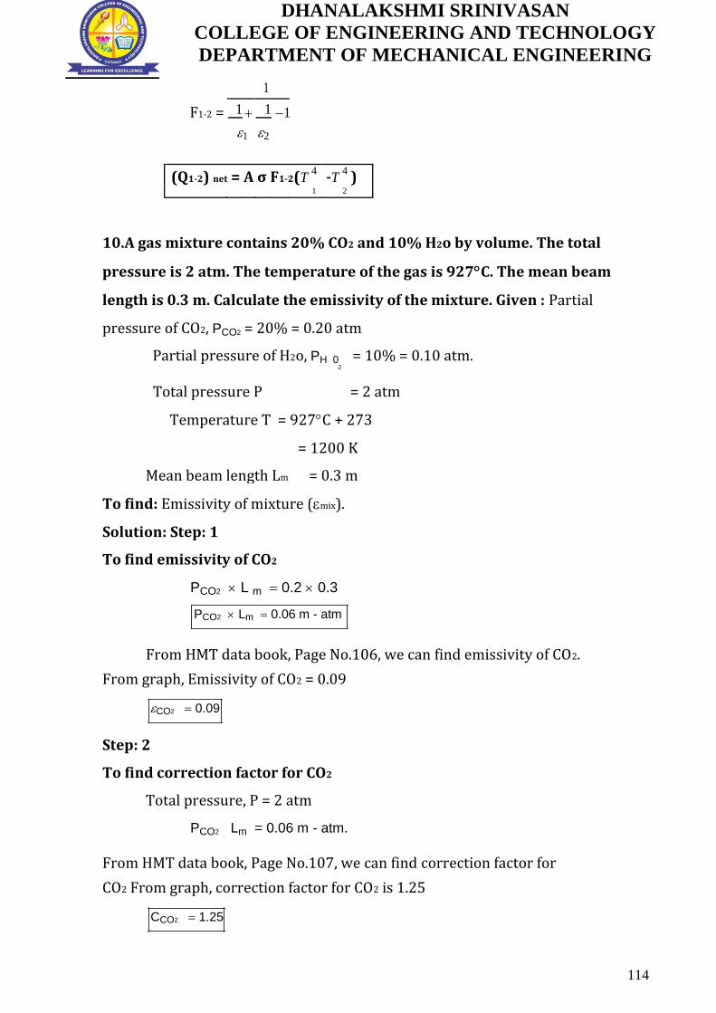
DHANALAKSHMI SRINIVASAN
COLLEGE OF ENGINEERING AND TECHNOLOGY
DEPARTMENT OF MECHANICAL ENGINEERING
F1-2 =
1
1 1 1
1 2
(Q1-2) net = A σ F1-2(T 4 -T 4 )
1 2
10.A gas mixture contains 20% CO2 and 10% H2o by volume. The total
pressure is 2 atm. The temperature of the gas is 927C. The mean beam
length is 0.3 m. Calculate the emissivity of the mixture. Given : Partial
pressure of CO2, PCO2 = 20% = 0.20 atm
Partial pressure of H2o, PH 0 = 10% = 0.10 atm. 2
Total pressure P = 2 atm
Temperature T = 927C + 273
= 1200 K
Mean beam length Lm = 0.3 m
To find: Emissivity of mixture (mix).
Solution: Step: 1
To find emissivity of CO2
PCO2 L m 0.2 0.3
PCO2 Lm 0.06 m - atm
From HMT data book, Page No.106, we can find emissivity of CO2.
From graph, Emissivity of CO2 = 0.09
CO2 0.09
Step: 2
To find correction factor for CO2
Total pressure, P = 2 atm
PCO2 Lm = 0.06 m - atm.
From HMT data book, Page No.107, we can find correction factor for
CO2 From graph, correction factor for CO2 is 1.25
CCO2 1.25
114
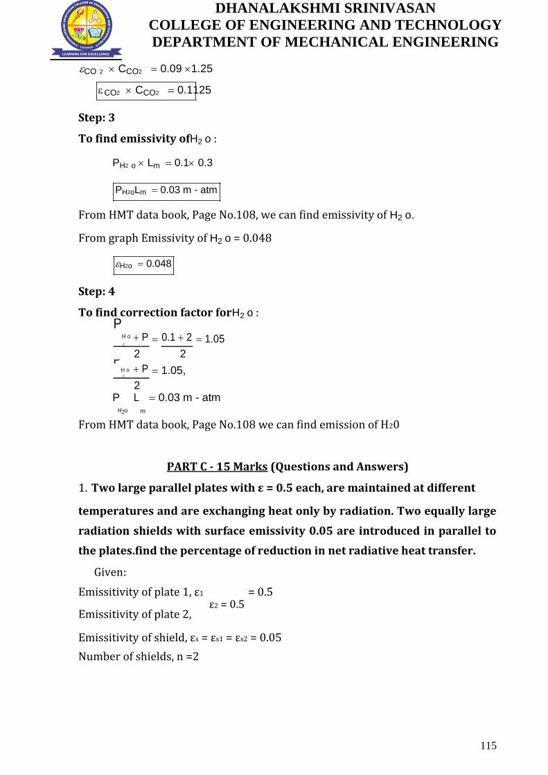
DHANALAKSHMI SRINIVASAN
COLLEGE OF ENGINEERING AND TECHNOLOGY
DEPARTMENT OF MECHANICAL ENGINEERING
CO 2 CCO2 0.09 1.25
CO2 CCO2 0.1125
Step: 3
To find emissivity ofH2 o :
PH2 o Lm 0.1 0.3
PH2oLm 0.03 m - atm
From HMT data book, Page No.108, we can find emissivity of H2 o.
From graph Emissivity of H2 o = 0.048
H2o 0.048
Step: 4
To find correction factor forH2 o :
P
H o P 0.1 2 1.05
2
2 2
P
H o P 1.05,
2
2
P L
m
0.03 m - atm
H2o
From HMT data book, Page No.108 we can find emission of H20
PART C - 15 Marks (Questions and Answers)
1. Two large parallel plates with ε = 0.5 each, are maintained at different
temperatures and are exchanging heat only by radiation. Two equally large
radiation shields with surface emissivity 0.05 are introduced in parallel to
the plates.find the percentage of reduction in net radiative heat transfer.
Given:
Emissitivity of plate 1, ε1 = 0.5
Emissitivity of plate 2,
Emissitivity of shield, εs = εs1 = εs2 = 0.05
Number of shields, n =2
115
ε2 = 0.5

DHANALAKSHMI SRINIVASAN
COLLEGE OF ENGINEERING AND TECHNOLOGY
DEPARTMENT OF MECHANICAL ENGINEERING
To find:
Percentage of reduction in net radiative heat transfer
Solution:
Case 1:
Heat transfer without radiation shield
Q12 = ε * ς * A * [ T14 – T24]
ε = 1 / (((1/ ε1) + (1/ ε2) -1 ))
ε = 1 / (((1/ 0.5) + (1/ 0.5) -1 ))
ε = 0.333.
Q12 = ε * ς * A * [ T14 – T24]
Q12 = 0.333 * ς * A * [ T14 – T24]
CASE 2: Heat transfer with radiation shield
Qwith shield = ( ς * A * [ T14 – T24] ) / ((1/ ε1) + (1/ ε2) + (2n / εs ) – (n+1))
= ( ς * A * [ T14 – T24] ) / ((1/ 0.5) + (1/ 0.5) + ((2*2) / 0.05) – (2+1))
= ( ς * A * [ T14 – T24] ) / 81
Qwith shield = 0.0123 * ( ς * A * [ T14 – T24] )
We know that
Radiation in heat transfer due to radiation shield
= ( QWITHOUT SHIELD - QWITH SHIELD ) / QWITHOUT SHIELD
= (( 0.333 * ς * A * [ T14 – T24]) - (0.0123 * ( ς * A * [ T14 – T24] )))
( 0.333 * ς * A * [ T14 – T24])
= 0.963
116
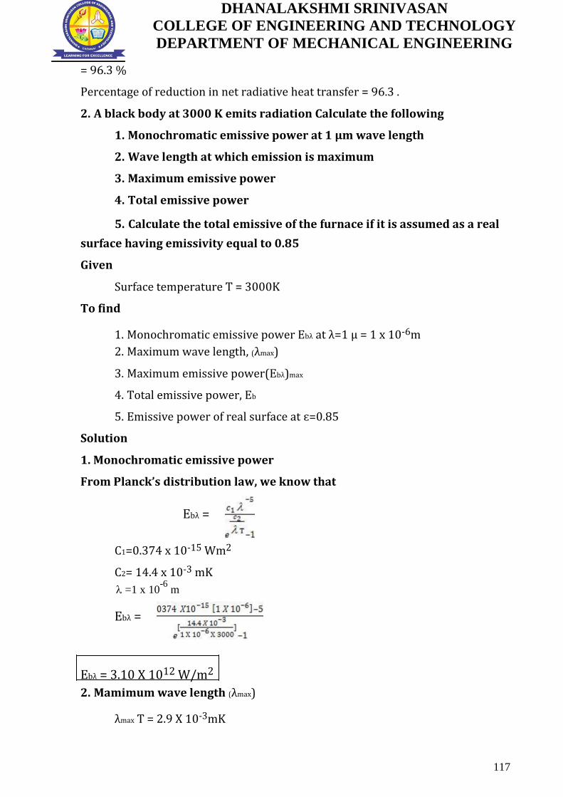
DHANALAKSHMI SRINIVASAN
COLLEGE OF ENGINEERING AND TECHNOLOGY
DEPARTMENT OF MECHANICAL ENGINEERING
= 96.3 %
Percentage of reduction in net radiative heat transfer = 96.3 .
2. A black body at 3000 K emits radiation Calculate the following
1. Monochromatic emissive power at 1 µm wave length
2. Wave length at which emission is maximum
3. Maximum emissive power
4. Total emissive power
5. Calculate the total emissive of the furnace if it is assumed as a real
surface having emissivity equal to 0.85
Given
Surface temperature T = 3000K
To find
1. Monochromatic emissive power Ebλ at λ=1 µ = 1 x 10⁻⁶m 2. Maximum wave length, (λmax)
3. Maximum emissive power(Ebλ)max
4. Total emissive power, Eb
5. Emissive power of real surface at ɛ=0.85
Solution
1. Monochromatic emissive power
From Planck’s distribution law, we know that
Ebλ =
C1=0.374 x 10⁻¹⁵ Wm2
C2= 14.4 x 10⁻³ mK
=1 x 10⁻⁶
m
Ebλ =
Ebλ = 3.10 X 10¹² W/m2
2. Mamimum wave length (λmax)
λmax T = 2.9 X 10⁻³mK
117

DHANALAKSHMI SRINIVASAN
COLLEGE OF ENGINEERING AND TECHNOLOGY
DEPARTMENT OF MECHANICAL ENGINEERING
λmax =
λmax = 0.966 X 10⁻⁶ m
3. Maximum emissive power (Ebλ)max
(Ebλ)max = 1.307 X 10⁻⁵ T5
= 1.307 X 10-5 X (3000)5
(Ebλ)max = 3.17 X 10¹² W/m2
4. Total emissive power Eb Eb = σ x T4 (From HMT data book P.No 8) σ = Stefen Boltzman Constant
= 5.67 x 10⁻⁸ W/m2 K4
Eb = (5.67 x 10-8) x (3000)4
Eb = 4.59 x 10⁻⁶ W/m2
5. Total emissive power of real surface (Eb)real = ɛ σ T 4
ɛ - Emissivity = 0.85
(Eb)real = 0.85 x 5.67 x 10-8 x
(3000)4 (Eb)real = 3.90 x 10⁶ W/m2 Result
1. Ebλ = 3.10 X 10¹² W/m2 2. λmax = 0.966 X 10⁻⁶ µm
3. (Ebλ)max = 3.17 X 10¹² W/m2 4. (Eb)real = 3.90 x 10⁶ W/m2
118

DHANALAKSHMI SRINIVASAN
COLLEGE OF ENGINEERING AND TECHNOLOGY
DEPARTMENT OF MECHANICAL ENGINEERING
UNIT: V MASS TRANSFER
PART A - 2 Marks (Questions and Answers)
1. What is mass transfer?
The process of transfer of mass as a result of the species
concentration difference in a mixture is known as mass transfer.
2. Give the examples of mass transfer.
Some examples of mass transfer.
1. Humidification of air in cooling tower
2. Evaporation of petrol in the carburettor of an IC engine.
3. The transfer of water vapour into dry air.
3. What are the modes of mass transfer? (Nov/Dec 2010)(Nov/Dec
2104) There are basically two modes of mass transfer,
1. Diffusion mass transfer 2. Convective mass transfer
4. What is molecular diffusion?
The transport of water on a microscopic level as a result of diffusion
from a region of higher concentration to a region of lower concentration in
a mixture of liquids or gases is known as molecular diffusion.
5. What is Eddy diffusion?
When one of the diffusion fluids is in turbulent motion, eddy
diffusion takes place.
6. What is convective mass transfer? (May/June 2006)
Convective mass transfer is a process of mass transfer that will
occur between surface and a fluid medium when they are at different
concentration.
7. State Fick’s law of diffusion. (April/May 2012) (NOV-DEC 14)( Nov/Dec
16)
The diffusion rate is given by the Fick’s law, which states that molar
flux of an element per unit area is directly proportional to concentration
gradient.
maA Dab
dCadx
Where,
119

DHANALAKSHMI SRINIVASAN
COLLEGE OF ENGINEERING AND TECHNOLOGY
DEPARTMENT OF MECHANICAL ENGINEERING
ma Molar flux, kg mole
A s m 2
Dab- Diffusion coefficient of species a and b,
m2/s dCa
dx Concentration gradient, kg/m3
8. What is free convective mass transfer?
If the fluid motion is produced due to change in density resulting
from concentration gradients, the mode of mass transfer is said to be free
or natural convective mass transfer.
Example: Evaporation of alcohol.
9. Define forced convective mass transfer.
If the fluid motion is artificially created by means of an external
force like a blower or fan, that type of mass transfer is known as convective
mass transfer.
Example: The evaluation if water from an ocean when air blows over
it.
10. Define Schmidt and Lewis number. What is the physical significance of
each? (NOV/DEC 13)
The dimensionless Schmidt number is defined as the ratio of momentum
diffusivity to mass diffusivity c = ν/DAB , and it represents the relative
magnitudes of momentum and mass diffusion at molecular level in the velocity
and concentration boundary layers, respectively. The Schmidt number diffusivity
corresponds to the Prandtl number in heat transfer. A Schmidt number of unity
indicates that momentum and mass transfer by diffusion are comparable, and
velocity and concentration boundary layers almost coincide with each other.
The dimensionless Lewis number is defined as the ratio of thermal
diffusivity to mass diffusivity Le = α / DAB and it represents the relative
magnitudes of heat and mass diffusion at molecular level in the thermal and
concentration boundary layers, respectively. A Lewis number of unity indicates
that heat and mass diffuse at the same rate, and the thermal and concentration
boundary layers coincide.
120

DHANALAKSHMI SRINIVASAN
COLLEGE OF ENGINEERING AND TECHNOLOGY
DEPARTMENT OF MECHANICAL ENGINEERING
11. Define Sherwood Number. (April/May 2012)
It is defined as the ratio of concentration gradients at the boundary.
Sc hmX
Dab
hm- Mass transfer coefficient, m/s
Dab-Diffusion coefficient, m2/s
X- length, m
12. What is mass average velocity?( May/June 2010)
The bulk velocity of mixture , in which different compents mat have
different mobilites ,is compared either on mass average . if luid mixture of two
components A and B if uA and uB are the mean velocties then the average velocity
is
u mass = (ρA uA+ ρB uB)/ ρA + ρB
13. Distinguish between mass concentration and molar concentration (April/May 2017) Mass Concentration
Mass of a component per unit volume of the mixture. It is expressed in kg/m3
Mass concentration =
Molar concentration
Number of molecules of a component per unit volume of the mixture. It
is expressed in Kg – mole /m3
Molar concentration=
14. Define schmidt number and state its physical significance. ) ( Nov/Dec
16)
Schmidt number (Sc) is a dimensionless number defined as the ratio of
momentum diffusivity (viscosity) and mass diffusivity, and is used to
characterize fluid flows in which there are simultaneous momentum and mass
diffusion convection processes.
Significance:
Analogous of Prandtl number in Heat Transfer. Used in fluid flows in
which there is simultaneous momentum & mass diffusion. It is also ratio of fluid
boundary layer to mass transfer boundary layer thickness.
121

DHANALAKSHMI SRINIVASAN
COLLEGE OF ENGINEERING AND TECHNOLOGY
DEPARTMENT OF MECHANICAL ENGINEERING
PART B - 13 Marks (Questions and Answers)
1. A vessel contains binary mixture of O2 and N2 with partial pressure in
the ratio 0.21 and 0.79 at 15oC =. The total pressure of the mixture is 1.1
bar. Calculate the following.
I. Molar concentrations
II. Mass densities
III. Mass fractions
IV. Molar fraction of each species.
[APRIL/MAY 2014; NOV/DEC 2015]
Given:
Partial pressure of O2 =0.21 x total
pressure (Po2)= 0.21 x 1.1
Po2= 0.231 x 10⁵ N/m2
So partial pressure of N2= PN2=86.9 x 10³ N/m2
Temperature T = 15o C =288 K
To find
I. Molar concentrations, o2, N2
II. Mass densities, ρO2, ρN2
III. Mass fractions, ṁO2,ṁN2
IV. Molar fraction of each species.xO2, XN2
Solution:
STEP-1
Molar concentration, co
po
2 2
GT
Universal Gas Constant, G= 8314 J/kg mole K
Co
0.231105
2 8314 288
Co2 9.64103
kg mole / m3
CN 2 p
N 2
GT
122

DHANALAKSHMI SRINIVASAN
COLLEGE OF ENGINEERING AND TECHNOLOGY
DEPARTMENT OF MECHANICAL ENGINEERING
C
86.9 10
3
N 2 8314 288
C N 2 0.036kg mole / m3
Total concentration,
C= Co2 + CN2 = 0.045 kg mole/m3
STEP-2
Molar concentration
C
O2 CO2 O2
= 9.64 x 10-3 x 32
O2 0.308kg / m3
=0.0362 x 28
N 2 1.013kg / m 3
Overall density, O2N2
= 0.308 + 1.10136
1.3216kg / m3
STEP-3
Mass fractions ṁ02 =
02
0.308
1.3216
ṁ02= 0.233
N 2 1.0136
ṁN2 =
1.3216
ṁN2 = 0.766
STEP-4
Mole fractions, X02 =
C02
9.64 103
C 0.045
XO2 = 0.210
C 0.0362
XN2 =
N 2
C 0.045
XO2 = 0.804
123
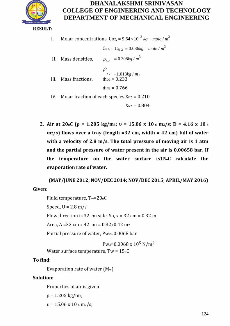
DHANALAKSHMI SRINIVASAN
COLLEGE OF ENGINEERING AND TECHNOLOGY
DEPARTMENT OF MECHANICAL ENGINEERING
RESULT:
I. Molar concentrations, Co2, = 9.64 103
kg mole / m3
CN2, = CN 2 0.036kg mole / m3
II. Mass densities, O2 0.308kg / m3
N 2 1.013kg / m 3
III. Mass fractions, ṁO2 = 0.233
ṁN2 = 0.766
IV. Molar fraction of each species.XO2 = 0.210
XN2 = 0.804
2. Air at 20oC (ρ = 1.205 kg/m3; υ = 15.06 x 10⁻⁶ m2/s; D = 4.16 x 10⁻⁶
m2/s) flows over a tray (length =32 cm, width = 42 cm) full of water
with a velocity of 2.8 m/s. The total pressure of moving air is 1 atm
and the partial pressure of water present in the air is 0.00658 bar. If
the temperature on the water surface is15oC calculate the
evaporation rate of water.
(MAY/JUNE 2012; NOV/DEC 2014; NOV/DEC 2015; APRIL/MAY 2016)
Given:
Fluid temperature, T∞=20oC
Speed, U = 2.8 m/s
Flow direction is 32 cm side. So, x = 32 cm = 0.32 m
Area, A =32 cm x 42 cm = 0.32x0.42 m2
Partial pressure of water, Pw2=0.0068 bar
Pw2=0.0068 x 10⁵ N/m2
Water surface temperature, Tw = 15oC
To find:
Evaporation rate of water (Mw)
Solution:
Properties of air is given
ρ = 1.205 kg/m3;
υ = 15.06 x 10⁻⁶ m2/s;
124

DHANALAKSHMI SRINIVASAN
COLLEGE OF ENGINEERING AND TECHNOLOGY
DEPARTMENT OF MECHANICAL ENGINEERING
Diffusion coefficient D = 4.16 x 10⁻⁶ m2/s
STEP-1
Re UL = 2.8 0.32
15.06 106
= 0.594 x 10⁵ < 5 x 10⁵
Since Re < 5 x 10⁵, flow is laminar
Flat plate laminar flow:
Sherwood number (Sh) = [0.664 (Re)0.5 (Sc)0.333] ........... {1}
[From HMT data book, P.no-175]
STEP-2
Sc
Schmidt number =
=
15.06 106
Da b
4.16 10
5
Sc = 0.3620
Sub Sc, Re in {1}
(Sh) = [0.664 (0.594 x 10⁵)0.5 (0.3620)0.333]
Sh= 115.37
STEP-3
Sherwood number Sh = h
m L
Da b
115.37
hm 0.32
4.16 105
hm= 0.0149 m/s
STEP-4
Mass transfer coefficient based on pressure difference is given
h hm = 0.0149 [Tw=15oC +273=288 K, So R= 287 J/kg K]
mp RTw
287 288
hmp=1.80x10⁻⁷ m/s
Saturation pressure of water at 15oC
Pw1=0.017 bar
Pw1 = 0.017 x 10⁵ N/m2 [From steam table (R.S khurmi) P.no-1]
STEP-5
The evaporation of water
125

DHANALAKSHMI SRINIVASAN
COLLEGE OF ENGINEERING AND TECHNOLOGY
DEPARTMENT OF MECHANICAL ENGINEERING
Mw = hmp x A (Pw1- Pw2)
Mw = 2.66 x 10⁻⁵ kg/s
Result:
The evaporation rate of water Mw = 2.66 x 10⁻⁵ kg/s
3. Dry air at 270c and 1 atm flows over a wet flat plate 50 cm long at a
velocity of 50 m/s. Calculate the mass transfer coefficient of water
vapour in air at the end of the plate.
(NOV/DEC 2014; APRIL/MAY 2015) (NOV/DEC 2013)
Given:
Fluid temperature T∞=270c
Velocity u=50 m/s
Length x = 35mm =0.035 m
To find:
Mass transfer co-efficient,(hm)
Solution:
STEP-1
Properties of at 270C:
V=16 x 10-6 m2/s
Re UL = 50 0.035
16 106
= 1.09375 x 10⁵ < 5 x 10⁵
Since Re < 5 x 10⁵, flow is laminar
Flat plate laminar flow:
Sherwood number (Sh) = [0.664 (Re)0.5 (Sc)0.333] ........... {1}
[From HMT data book, P.no-175]
STEP-2
[D ab-Diffusion coefficient (water+ air) @ 270c = 25.38 x10⁻⁶ m2/s]
126

DHANALAKSHMI SRINIVASAN
COLLEGE OF ENGINEERING AND TECHNOLOGY
DEPARTMENT OF MECHANICAL ENGINEERING
Sc
Schmidt number =
=
16 106
D a b 25.38 106
Sc = 0.6304
STEP-3
Sub Sc, Re in {1}
(Sh) = [0.664 (1.09375 x 10⁵)0.5 (0.6304)0.333]
Sh= 188.32
STEP-4
Sherwood number Sh = h
m L
Da b
188.32
hm 0.35
25.38 106
hm= 0.1365 m/s
Result:
Mass transfer coefficient of water vapour hm= 0.1365 m/s.
4. CO2 and air experience equimolar counter diffusion in a circular tube
whose length and diameter are 1 m and 50 mm respectively. The
system of total pressure of 1 atm and a temperature of 250C. The ends
of the tube are connected to large chambers in which the species
concentrations are maintained at fixed values.the partial pressure of
CO2at one end is 190 mm of Hg while at the other end is 95 mm Hg .
Estimate the mass transfer rate of CO2and air through the tube.
[MAY/JUNE 2012; APRIL/MAY 2016]
Given:
Diameter,d=50mm=0.05m
Length=1m [x2-x1]
Total pressure ,p=1 atm =1bar
Temperature,T=250C= 298 K
Parital pressure of CO2 at one end
Pa1=190mm of Hg= 190
760 bar
127

DHANALAKSHMI SRINIVASAN
COLLEGE OF ENGINEERING AND TECHNOLOGY
DEPARTMENT OF MECHANICAL ENGINEERING
Pa1= 0.25bar [1bar= 760 mm of Hg]
Pa1= 0.25x10⁵N/m2 [1 bar = 105 N/mm2]
Parital pressure of CO2 at other end
Pa2=95mm of Hg= 76095
bar
Pa2= 0.0312 bar [1bar= 760 mm of Hg]
Pa2= 0.0312x10⁵N/m2 [1 bar = 105 N/mm2]
To find:
1.Mass transfer rate of Co2
2. Mass transfer rate of air
Solution:
STEP-1
ma
Dab
[Ca1
C
a2]
A GT [ X 2 X 1 ]
Diffusion coefficient (Dab) for CO2-Air combination is 11.89x10⁻⁶ m2/s [HMT
data book page no.180]
J
G-Universal gas constant -8314 kg mole K (J/kg-mole-K)
A-Area
4 (d)2
A=1.9634x10⁻³ m2
ma
Dab [Ca1 Ca 2 ]
A
GT [ X 2 X 1 ]
m a 11.89 106
[0.25 105 0.03110
5 ]
8314 298
[1]
A
Molar transfer rate of Co2, ma = 1.050 x 10⁻⁷ kg
mole
s
STEP-2
We know,
Mass Transfer Rate Co2 = Molar Transfer x Molecular Weight
= 1.050 x 10-7 x 44.01
[Molecular weight of Co2 Refer HMT D.B Page 182]
Mass Transfer Rate Co2 = 4.625 x 10⁻⁶ kg/s
128

DHANALAKSHMI SRINIVASAN
COLLEGE OF ENGINEERING AND TECHNOLOGY
DEPARTMENT OF MECHANICAL ENGINEERING
Mass Transfer Rate of Air = mb= -1.050 x 10⁻⁷ kg
mole
s
STEP-3
[ ma= -mb]
Mass Transfer Rate Air = Molar Transfer x Molecular Weight of air
= 1.050 x 10-7 x 29
Mass Transfer Rate Air = -3.045 x 10⁻⁶ kg/s
Result:
1.Mass transfer rate of Co2 = 4.625 x 10⁻⁶ kg/s
2. Mass transfer rate of air = -3.045 x 10⁻⁶ kg/s
5. Discuss briefly the Analogy between heat and mass transfer.
[MAY/JUNE 2013; NOV/DEC 2015; APRIL/MAY 2016]
There is similarity among heat and mass transfer. The three basic
equations dealing with these are
I. Newtonian equation of momentum
II. Fourier law of heat transfer
III. Fick law of mass transfer
The momentum, heat and mass transfer equation can be written
as Continuity equation, dx
u dy
v 0
Momentum transfer, u u
v v
v
2 u
dx dy dy 2
Heat transfer, u T
v T
2 u
x y
y 2
Mass transfer, u Ca
v Cn
D
2 Ca
x
y
y 2
Heat and mass transfer takes place due to temperature difference. As per
Fourier’s law of conduction
Q kA
dt
dx
Where Q= rate of heat transfer
K= thermal conductivity of material
129

DHANALAKSHMI SRINIVASAN
COLLEGE OF ENGINEERING AND TECHNOLOGY
DEPARTMENT OF MECHANICAL ENGINEERING
A= Heat transfer area
dxdt
= Temperature gradient
As per Newton’s law of cooling
Q hAT
Where h= heat transfer coefficient
Mass transfer takes place due to concentration difference.
As per Fick’s law of diffusion
Na m
A DAB
dC A
A dx
mA = Mass flow rate of species A by
diffusion. A = Area through which mass is
flowing DAB = Diffusion coefficient.
dCdx
A = concentration gradient.
6. Explain Equimolar Counter diffusion in gases.
[APRIL/MAY 2013; NOV/DEC 2014]
Two large chambers ‘a’ and ‘b’ connected by a passage as shown
below.
130

DHANALAKSHMI SRINIVASAN
COLLEGE OF ENGINEERING AND TECHNOLOGY
DEPARTMENT OF MECHANICAL ENGINEERING
Na and Nb are the steady state molar diffusion rates of component a and b
respectively.
Equimolar diffusion is defined as each molecule of ‘a’ is replaced by each
molecule of ‘b’ and vice versa. The total pressure p pa pb is uniform throughout
the system.
P Pa Pb
Differentiating with respect to x
dPdx
dPadx
dPbdx
Since the total pressure of the system remains constant under steady state
conditions
dPdx
dPadx
dPbdx 0
dPadx
dPadx
Let the total molar flux is zero, Na + Nb = 0
Na = -Nb
D A dPa D A dPb
From flick’s law, BA GT dx BA GT dx
DAB = DBA = D
ma A 2 dPA
Na
D
A GT dx
1
131

DHANALAKSHMI SRINIVASAN
COLLEGE OF ENGINEERING AND TECHNOLOGY
DEPARTMENT OF MECHANICAL ENGINEERING
Na ma D A Pa1 Pa2
x2 x1
Molar flux,
A
GT
Similarly,
Nb mb D A Pb1 Pb2
x2 x1
A
GT
Where,
ma Molar flux kg mole
A s m 2
D- Diffusion coefficient
G- Universal constant- 8314
J
kg mole K
A- Area – m2
Pa1- Partial pressure of constituent at 1 in N/m2
Pa2- Partial pressure of constituent at 2 in N/m2
T – Temperature – K
7. An open pan of 150 mm diameter and 75 mm deep contains water at
25oC and is exposed to atmosphere air at 25oC and 50oC R.H. calculate
the evaporation rate of water in grams per hour.
[APRIL/MAY 2002]
Given:
Diameter, d = 150 mm = 0.150 m
Deep, (x2-x1) = 75 mm = 0.075 m
Temperature, T = 25oC+273 = 298 K
Relative Humidity = 50%
To Find:
Evaporation rate of water in grams per hour.
Solution:
Diffusion co-efficient (Dab) [water + air] at
25oC [From HMT data book, page no, 180]
132

DHANALAKSHMI SRINIVASAN
COLLEGE OF ENGINEERING AND TECHNOLOGY
DEPARTMENT OF MECHANICAL ENGINEERING
Dab = 25.83 x 10⁻⁶
m2/s STEP-1
We know that, for isothermal evaporation,
ma
Dab p P Pw2
Molar flux,
ln
A GT x
2
x P Pw1
1
Area, A = 0.0176 m2
P = Total pressure = 1 atm = 1.013 x 10⁵
N/mm2
Pw1 = Partial pressure at the bottom
of the test tube corresponding to
saturation temperature 25oC.
At 25oC
Pw1 = 0.03166 x 10⁵N/mm2
[From steam table p.no 2]
Pw2 = Partial pressure at the top of the pan corresponding to 25oC and
50oC relative humidity.
At 25oC
Pw2 = 0.03166 x 10⁵ R.H = 50% = 0.50
Pw2 = 0.03166 x 105 x 0.50
Pw2 = 1583 N/m2
STEP-2 ma
25.83 106
1.013 105 1.013 10
5 1583
ln
298
5 5
0.076
8314
0.075 1.013 10
0.03166 10
Molar rate of water vapour, ma = 3.96 x10⁻⁹ kg
mole
s
STEP-3
Mass rate of water vapour = molar rate of water vapour X molecular
weight of steam
= 3.96 x 10-9 x 18.016 kg/s
Mass rate of water vapour = 0.256 g/h
Result:
133

DHANALAKSHMI SRINIVASAN
COLLEGE OF ENGINEERING AND TECHNOLOGY
DEPARTMENT OF MECHANICAL ENGINEERING
Evaporation rate of water = 0.256 g/h.
Evaporation rate of water = 0.256 g/h.
PART C - 15 Marks (Questions and Answers)
1. Two large tanks ,maintained at the same temperature and pressure
are connected by a circular 0.15m diameter direct, which is 3 m length
.One tank contains a uniform mixture 0f 60 mole % ammonia and 40 mole
% air and other tank contains a uniform mixture of 20 mole % ammonia
and 80 mole % air. The system is at 273 K and 1.013 x 10 5 pa . Determine
the rate of ammonia transfer between the two tanks.Assuming a steady
state mass transfer.
Given:
Diameter d= 0.15 m
Length (x2-x1)=3 m
Pa1= 60 =0.6 bar = 0.6 x 10⁵ N/m2
40
Pb1= 40 =0.4 bar = 0.4 x 10⁵ N/m2
40
Pa2= 20 =0.2 bar = 0.2 x 10⁵ N/m2
40
Pb2= 80 =0.8 bar = 0.8 x 10⁵ N/m2
40
T= 273 K
P=1.013 x 10⁵ N/m2
a-Ammonia
b-Air
To find
Rate of ammonia transfer
Solution:
134

DHANALAKSHMI SRINIVASAN
COLLEGE OF ENGINEERING AND TECHNOLOGY
DEPARTMENT OF MECHANICAL ENGINEERING
Equimolar counter diffusion
Molar flux,
Where G –universal constant =8314 J/Kg-mole-K
A= area=
A=
A=0.017 m2
Dab-Diffusion co efficient of ammonia with air = 21.6 x 10⁻⁶
m2/s (From HMT data book P.No 180 (sixth edition)
Dab = 21.6 x 10⁻⁶
m2/s
(1) = Molar
transfer rate of ammonia ,ma = 2.15 X 10⁻⁹
Kg-mole/s
Mass transfer rate of ammonia = Molar transfer rate of ammonia x
Molecular weight of ammonia
= 2.15 X 10-9
x17.03 (Refer HMT data book P.No
182) Mass transfer rate of ammonia = 3.66 x 10⁻⁸
Kg/s
Result
Mass transfer rate of ammonia = 3.66 x 10⁻⁸
Kg/s
2. An open pan 20cm in diameter and 8 cm deep contains water at 25 and is exposed to dry atmospheric air.If the rate of diffusion of water
vapour is 8.5 x 10⁻⁴
kg/h, estimate the diffusion co efficient of water in air.
Given :
Diameter d= 20 cm = 0.20 m
Length (x2-x1) = 8 cm = 0.08 m
Temperature T = 25 + 273 = 298 K
Diffusion rate (or)
Mass rate of water vapour = 8.54 x 10⁻⁴
kg/h
135

DHANALAKSHMI SRINIVASAN
COLLEGE OF ENGINEERING AND TECHNOLOGY
DEPARTMENT OF MECHANICAL ENGINEERING
=
= 2.37 x 10⁻⁷
kg/s
To find
Diffusion co efficient Dab
Solution
Molar rate of water vapour
We know that
Mass transfer rate of steam = Molar transfer rate of steam x Molecular weight of steam
Where
Area A=
=
A= 0.0314 m2
G –universal constant =8314 J/Kg-mole-K
P- Total Pressure = 1 atm = 1.013 bar = 1.013 x 10⁵ N/m2
136

DHANALAKSHMI SRINIVASAN
COLLEGE OF ENGINEERING AND TECHNOLOGY
DEPARTMENT OF MECHANICAL ENGINEERING
Pw1- Partial pressure at the bottom of the test tube corresponding to saturation
temperature 25
At 25 (From Rs Khurmi Steam table P.No 2)
Pw1 = 0.03166 x 10⁵ N/m2
Pw2- Partial pressure at the top of the pan Hence air is dry and there is no water
vapour So, Pw2 =0
Pw2 =0
(1) =
Dab = 2.58 x 10⁵ m2/s
Result
Diffusion coefficient , Dab = 2.58 x 10⁵ m2/s
137

DHANALAKSHMI SRINIVASAN
COLLEGE OF ENGINEERING AND TECHNOLOGY
DEPARTMENT OF MECHANICAL ENGINEERING
B.E/B.Tech DEGREE EXAMINATION, APR/MAY 2017.
Fifth Semester
Mechanical Engineering
ME 6502 – HEAT AND MASS TRANSFER
(Regulation 2013)
Time: Three hours
Maximum: 100 marks
Answer ALL questions
PART A – (10 x 2= 20 marks)
1. Distinguish between conduction and convection heat transfer 2. State some practical applications of transient heat transfer analysis. 3. How Reynolds and Colburn analogies differ with each other. 4. Define Grashof number and explain its significance in free convection heat
transfer. Refer page No.36, Question No.4 5. Draw the pool boiling curve for water 6. Sketch the temperature variation of condenser and evaporator 7. State Lamberts cosine law for radiation Refer page No.93, Question No.13 8. What are the application of radiation shields? Refer page No.94,
Question No.16 9. Distinguish between mass concentration and molar
concentration. Refer page No.121, Question No.13 10. Give examples for free and forced convection mass transfers.
PART B– (5 x 16= 80 marks)
11. A) i) Steam at 320 flows in a cast pipe (k=80 W/mK) whose inner and outer diameter are D1=5cm and D2 = 5.5cm, respectively. The pipe is covered with 3-cm thick glass wool insulation with k=0.05 W/mK. Heat is lost to the surroundings at 5 by natural convection and radiation, with a combines heat transfer coefficient of h2= 18 W/m2K.Taking the heat transfer coefficient inside the pipe to be h1= 60 W/m2K.Determine the rate of heat loss from the
steam per unit length of the pipe. Also determine the temperature drops
across the pipe shell and the insulation. (10)
Refer page No.20, Question No.5 (similarity)
(ii) Write short notes on types of extended surfaces or fins (6)
(Or)
B) i) Circumferential aluminium fins (k= 200 W/mK) of rectangular profile (1.5cm x 1cm thick) are fitted onto a 2.5cm diameter tube. The fin base temperature is 170 and the ambient air temperature is 25 .Estimate the heat loss per fin .The heat transfer coefficient “h” may be taken as 130 W/m2K
Refer page No.25, Question No.8 (similarity) (8) (ii) The ground at a particular location is covered with snow pack at -10 for
a continuous period of three months and the average soil properties at that location are k=0.4 W/mK and α=0.15 x 10⁻⁶ m2/s. Assuming an initial uniform temperature of 15 for the ground, determine the minimum burial depth to
prevent the water pipes from freezing. (8)
138

DHANALAKSHMI SRINIVASAN
COLLEGE OF ENGINEERING AND TECHNOLOGY
DEPARTMENT OF MECHANICAL ENGINEERING
12 a) i) Air flows a flat plate at a velocity of 10m /s .Air and surface temperature of the plate are 20 and 580 respectively. Calculate the amount of heat
transferred per meter width from both sides of the plate over a distance of 40cm from the leading edge. Refer page No.42, Question No.2 (similar) (8)
(ii) Engine oil flows through a 50mm diameter tube at an average temperature of 147 .the flow velocity is 80 cm/s. Calculate the average heat transfer coefficient if the tube wall is maintained at a temperature of
200 and it is 2 m long ? (8)
(Or)
b) Consider a 0.6m x 0.6 m thin square plate in a room at 30 .One side
of the plate is maintained at a temperature of 90 , while the other side is
insulated. Determine the rate of heat transfer from the plate by natural convection if the plate is (i)vertical (ii)horizontal with hot surface facing up, and (iii)horizontal with hot surface facing down.
13 (a) Water is to be boiled at atmospheric pressure in a mechanically polished stainless steel pan placed on top of a heating unit the inner surface of the bottom of the pan is maintained at 108 . If the diameter of the bottom of the pan is 30cm, determine (i) the rate of heat transfer to the water and(ii)the rate of evaporation of water. Refer page No.70, Question No.2 (similar) (16)
(Or)
(b) A shell passes and 4 tube passes heat exchanger is used to heat glycerin from 20 to 50 by hot water which enters the thin –walled 2 cm diameter tubes at 80 and leaves at 40 .the total length of the tubes in the
heat exchanger is 60cm. the convection heat transfer coefficient is 25 W/m2K on the glycerin (shell) side and 160W/mK on the water (tube)side. determine the rate of heat transfer in the heat exchanger (i)before any fouling and (ii)after fouling with a fouling factor of 0.0006 m2 k/w occurs on the outer
surfaces of the tubes.. (16)
14. a) (i) The filament of a round bulb is maintained at a temperature of 2000k and it is assumed to be black body .The transmissivity of the bulb glass is 0.92 in
the visible range (0.65<λ<0.75µm)of the radiation. Calculate the amount of
energy transmitted. (8)
(ii) The surfaces of a double walled spherical vessel used for storing liquid oxygen are covered with a layer of silver having an emissivity of 0.03.The temperature of the outer surface of the inner wall is -153 and the temperature of the inner surface of the outer wall is 27 . The spheres are 21cm and 30cm in diameter ,with the space between them evacuated .Calculate the radiation heat transfer through the walls into the vessel and the rate of evaporation of liquid oxygen if its rate of vaporization is 220kj/Kg. (8)
(Or)
b) Two parallel plates 2 m x1 m are spaced 1m apart .The plates are at a temperature of 727 and 227 and their emissivities are 0.3 and 0.5
139

DHANALAKSHMI SRINIVASAN
COLLEGE OF ENGINEERING AND TECHNOLOGY
DEPARTMENT OF MECHANICAL ENGINEERING
respectively. The plates are located in a large room, the walls of which are at 27 . determine the rate of heat loss from each plate and heat gain by the
walls. Refer page No.101, Question No.3 (similarity) (16)
15. a) Two large vessel contain uniform mixture of air and sulphur dioxide at 1 atm and 273k but at difference concentration. Vessel 1 contains 80 % air and
20 % So2 by volume or mole percentage whereas vessel 2 contains 30% air and 70 % SO2 by mole percentage. .The vessels are connected by a 10 cm
inner diameter 1.8m long pipe .Determine the rate of transfer of air between
these two vessels by assuming that a steady state transfer takes place .the mass diffusity of air SO2 mixture at 1 atm 273 k is 0.122x10⁻⁴ m2/s (16) Refer page No.134, Question No.1 (similarity)
(Or)
b) The water in a 5 cm 15 m outdoor swimming pool is maintained at a temperature of 27 . The average temperature and relative humidity are 37
and 40 % respectively. Assuming a wind speed of 2 m/s in the direction
of the long side of the pool. Estimate the mass transfer coefficient for the evaporation of water from the pool surface and the rate of evaporation in
Kg/day. Refer page No.132, Question No.7 (similarity) (16)
140
DHANALAKSHMI SRINIVASAN
COLLEGE OF ENGINEERING AND TECHNOLOGY
DEPARTMENT OF MECHANICAL ENGINEERING
B.E/B.Tech DEGREE EXAMINATION, NOV/DEC 2016.
Fifth Semester
Mechanical Engineering
ME 6502 – HEAT AND MASS TRANSFER
(Regulation 2013)
Time: Three hours Maximum: 100 marks
Answer ALL questions
PART A – (10 x 2= 20 marks)
1. State the Fourier’s law of heat conduction. Why is the negative sign used? Refer page No.9, Question No.1
2. Under what circumstances from the heat transfer point of view, will the use of finned walls be better?
3. What are the differences between natural and forced convection? Refer page No.39, Question No.14
4. What is critical Reynolds number for the flow over the flat plate? Refer page No.35, Question No.1
5. Give examples for pool boiling and flow boiling. Refer page No.66, Question No.7
6. What are the fouling factors? 7. Define monochromatic emissive power. Refer page No.94, Question No.17 8. What do you mean by infrared and ultraviolet
radiation Refer page No.94, Question No.18 9. State Fick’s law of diffusion.
10. Define Schmidt number and state its physical significance. Refer page No.120, Question No.10
PART B– (5 x 16= 80 marks)
1. A) i) A body of an electric motor is 360 mm in diameter and 240mm long. It dissipates 360W of heat and its surface temperature should not exceed 55OC. longitudinal fins of 15 mm thickness and 40 mm height are proposed. The heat transfer coefficient is 40 W/ m2 K when the ambient temperature 30OC. Determine the number of fins required, if K of the fine material is 40 W/m K.
(10)
(ii) Derive an expression for critical radius of insulation for a cylindrical
system. (6)
(Or)
B) (i) Determine the minimum depth at which one must place a water main below the soil surface to avoid freezing. The soil is initially at a uniform temperature of 20OC. in severe winter condition it is subjected to a temperature of -15oC for a period of 60 days. Use the following properties of the soil: ρ = 2050 kg/m3, C = 1840 j/kg K and k = 0.52 W/m K. (8)
(ii) A steel pipe with 50mm OD is covered with two layers of insulation. The inner layer is 7.5mm thick and has a k = 0.3 W/m K and the top layer is
141

DHANALAKSHMI SRINIVASAN
COLLEGE OF ENGINEERING AND TECHNOLOGY
DEPARTMENT OF MECHANICAL ENGINEERING
20mm thick and k = 0.12 W/m K. The pipe wall is 315 OC and the outside air temperature is 25 OC. determine the surface temperature and heat loss per metre length for 10 minutes. Take the convective heat transfer coefficient
between air the surface as 16 W/ m2 K. (8)
12. a) (i) Define velocity boundary layer and thermal boundary layer. (4) Refer page No.48, Question No.5
(ii) Air at 200 kPa and 200 is heated as it flows through a tube with a
diameter of 25 mm at a unit length of the tube. If a constant heat flux condition is maintained at the wall and the wall temperature is 20 above the air temperature, all along the length of the tube. How much would the
bulk temperature increases over 3 m length of the tube? (12)
(Or)
b) (i) A 0.5 m high flat plate of glass at 93 is removed from an
annealing furnace and hung vertically in the air at 28 , 1 atm. Calculate the
initial rate of heat transfer to the air. The plate is 1 m wide. (10)
Refer page No.44, Question No.3 (similarity)
(ii) A fine wire having a diameter of 0.02 mm is maintained at a constant temperature of 54 by an electric current. The wire is exposed to air at 1 atm. and 0 . Calculate the electric power necessary to maintain the wire temperature if the length is 50 cm. (6)
13. (a) The bottom of copper pan, 300 mm in diameter is maintained at 120 by an electric heater. Calculate the power required to boil water in this pan. What is the evaporation rate? Estimate the critical heat flux. (16)
(Or)
(b) Water at the rate of 4 kg/s is heated from 40 to 55 in a shell and
tube heat exchanger. On shell side one pass is used with water as heating fluid ( = 2kg/s), entering the exchanger at 95 .The overall heat transfer coefficient is 1500 W/m2 and the average water velocity in the 2 cm diameter tubes is 0.5 m/s. Because of space limitations the tube length must not exceed 3 m. calculate the number of tube passes, keeping in mind the
design constraint. (16) Refer page No.85, Question No.10
14. a) (i) A gray, diffuse opaque surface ( ) is at 100 and receives an irradiation 1000 W/m2. If the surface area is 0.1 m2. Calculate
1) Radiosity of the surface 2) Net radiative heat transfer rate from the surface
3) Calculate above quantities, if surface is black. (10) (ii) Emissivities of two large parallel plate maintained at 800 and 300 and
0.3 and 0.5 respectively. Find the net radiant heat exchange per square metre
for these plates. (6)
Refer page No.101, Question No.3
(Or)
142
DHANALAKSHMI SRINIVASAN
COLLEGE OF ENGINEERING AND TECHNOLOGY
DEPARTMENT OF MECHANICAL ENGINEERING
b) Two rectangels 50 x 50 cm are placed perpendicular with common edge. One surface has T1 = 1000 K, = 0.6, while the other surface is insulated and in
radiant balance with a large surrounding room at 300 K. Determine the temperature of the insulated surface and heat lost by the surface at 1000 K.
15. a) Air is contained in a tyre tube of surface area 0.5 m2 and wall thickness 10 mm. The pressure of air drops from 2.2 bar to 2.18 bar in a period of 6 days. The solubility of air in the rubber is 0.072 m3 of air per m3 of rubber at 1 bar. Determine the diffusivity of air in rubber at operating temperature of 300 K if the volume of air in the tube is 0.028 m3.
(Or)
b) Along a horizontal water surface an air stream with velocity uc = 3m/s is
flowing. The temperature of the water on the surface is 15 , the air temperature
is 20 the total pressure is 1 atm (106 N/m2), and the saturation pressure of the
water vapour in the air at 20 is 2337 N/m2. The relative
humidity of the air is 33%. The water surface along the wind direction has a length of 10 cm. calculate the amount of water evaporated per hour per meter from the water surface. The binary diffusivity of water vapour in the air may be taken as 3.3 x 10⁵ m2/s. The saturation vapour pressure of water at 15 1705 N/m2 and kinematic viscosity of the air is 1.5 x 10⁻⁵ m2/s.
143

DHANALAKSHMI SRINIVASAN
COLLEGE OF ENGINEERING AND TECHNOLOGY
DEPARTMENT OF MECHANICAL ENGINEERING
B.E/B.Tech DEGREE EXAMINATION, MAY/JUNE 2016.
Fifth Semester
Mechanical Engineering
ME 6502 – HEAT AND MASS TRANSFER
(Regulation 2013)
Time: Three hours Maximum: 100 marks
Answer ALL questions
PART A – (10 x 2= 20 marks)
1. What are the modes of heat transfer? Give examples. 2. What is lumped capacitance analysis?
3. Differentiate forced and free convection
Refer page No.39, Question No.14 4. Differentiate hydrodynamic boundary layer and thermal boundary
layer. Refer page No.40, Question No.15 5. What is black body radiation?
6. Define emissive power and monochromatic
emissivity. Refer page No.94, Question No.17 7. What are the assumptions made in Nusselt theory of condensation? 8. What is fouling and how does it affect the rate of heat transfer? 9. Define Fick’s law.
Refer page No.119, Question No.7 10. Diffusivity of ammonia in air at temperature 300C and pressure 1 atm, is
0.228cm2/sec. find the diffusivity of ammonia in cm2/sec in air at temperature500C and pressure 1.1 atm.
PART B– (5 x 16= 80 marks)
11. (a) Write short notes on :
(i) Heat transfer with extended surfaces (3)
(ii) Critical radius of insulation (3)
(iii) A flat furnace wall is constructed of 114 mm layer of sil-o-gel
brick with a thermal conductivity of 0.318 W/moC backed by a
229mm layer of common brick of conductivity 1.38 W/moC.
The temperature of inner face of the wall is 760oC and that of
the outer face is 76.6oC. (a) What is the heat loss through
composite wall? (b) What is the temperature of interface
between refractory brick and common brick? (10)
(OR)
(b) (i) A plane wall 10 cm thick generates heat at the rate of 4 x 10⁴
W/m3, when electric current is passed through it. The conductive heat transfer coefficient between each phase of wall and ambient air is 50
144
DHANALAKSHMI SRINIVASAN
COLLEGE OF ENGINEERING AND TECHNOLOGY
DEPARTMENT OF MECHANICAL ENGINEERING
W/m2oC. The thermal conductivity of wall is 15 W/mo C (a) derive the temperature profile for given slab; (b) determine the surface temperature,
(c) the maximum temperature in the wall. (10)
Refer page No.22, Question No.6
(ii) What is the significance of Heisler charts in transient heat
conduction? (6)
12. (a) (i) Explain about three layer model for internal convection n tubular
flow. (8)
(ii) A fluid of kinematic viscosity equal to 15 x 10-6 m2/s flows with an average velocity of 10 m/s in a square duct of 0.08 x 0.08 m cross section. What is the Reynolds number based on the hydraulic diameter? Is the flow laminar or turbulent? What is the Nusselt number if the flow is fully developed and the Prandtl number is 0.7? (8)
(OR)
(b) (i) Explain about thermal boundary layer flow past a flat plate. (6)
(ii) Consider flow of air at atmospheric pressure and 300 K parallel to a flat plate 2 m long. The viscosity of air far away from the plate is 10 m/ sec. the plate surface is held at a constant temperature of 400 K. Determine the heat transfer coefficient at the trailing edge of the plate using the colburn analogy ? Data: Properties at film temperature are: Density 0.995 kg/ m3, kinematic viscosity 20.92 x 10⁻⁶ m2/s, thermal conductivity 0.03 W m-1k-1.
Prandtl number 0.7. (10)
13. (a) (i) Hot water enters a counter flow exchanger at 95oC. This hot water is
used to heat a cool stream of water from 8 to 40oC. The flow rate of the cool
water is 1.2 kg/s, and that of the hot water is 2.7 kg/s. the overall heat
transfer coefficient is 850 W/m2oC. What is the area of the heat exchanger
and its effectiveness? (10)
(ii) Name and brief the different types of heat exchangers (6)
Refer page No.80, Question No.8
(OR)
(b) (i) A hot stream is cooled from 120oC to 30oC while the cold stream
temperature changes from 20 to 60oC. Find out the LMTD for both counter
and co-current phenomenon. Justify how counter current is effective than
co-current? (10)
(ii) What is flow boiling and pool boiling? Describe how heat transfer
coefficient varies in regimes of pool boiling. (6)
Refer page No.61, Question No.1
145

DHANALAKSHMI SRINIVASAN
COLLEGE OF ENGINEERING AND TECHNOLOGY
DEPARTMENT OF MECHANICAL ENGINEERING
14. (a) (i) Determine an expression for heat transfer rate by using electrical analogy (i)Without any shield between 2 parallel plates (ii) with shield in
between 2 parallel plates. (16)
(OR)
(b) (i) What is view factor and shape factor ? (5)
(ii) State laws of blackbody radiation? (5)
(iii) Two large parallel plates are at temperature T1= 500K and T2= 300
K. Their emissivities are є1=0.85 and є2= 0.90. What is the radiant flux
between the plates? (6)
15. (a) (i) derive an expression for mass flux in steady state moleculer diffusion
(a) A through non diffusing B.
(b) Equimolar Counter Diffusion. (8)
(ii) NH3gas (A) diffuses through N2 (B) under steady state condition with non-diffusing N2. The total pressure is 101.325 K pa and temperature is 298 K. the diffusion thickness is 0.15x10⁴ pa and at the other point is 5 x 10³ pa. the DAB for mixture at 1 atm and 298 K is 2.3x10⁻⁵ m2 /sec. (a) Calculate flux of NH3.(A through non diffusing B). Calculate flux for
equimolar counter diffusion. (8)
(OR)
(b) (i) Write a note on convective mass transfer coefficients for liquids and
gases. (8)
(ii) Give a brief description on heat, momentum and transfer analogies. (8)
146

DHANALAKSHMI SRINIVASAN
COLLEGE OF ENGINEERING AND TECHNOLOGY
DEPARTMENT OF MECHANICAL ENGINEERING
B.E/B.Tech DEGREE EXAMINATION, MAY/JUNE 2016.
Fourth Semester
Mechanical Engineering
ME 2251 – HEAT AND MASS TRANSFER
(Regulation 2008)
Time: Three hours Maximum: 100 marks
Answer ALL questions
PART A – (10 x 2= 20 marks)
1. List the differences between thermodynamics and heat transfer Refer page no.12, Question no.13
2. State the assumptions on which the fourier’s law of conduction is based.
3. What is the difference between friction factor and friction co-efficient? Refer page no.39, Question no.13
4. Why heat transfer co-efficient of natural convection is much less than
those forced convection? Refer page no.38, Question no.9
5. What is a compact heat exchanger? Give applications. Refer page no.67, Question no.12
6. Define effectiveness and NTU of a heat
exchanger. Refer page no.64, Question no.10 & 2. 7. Define radiation intensity. 8. Differentiate black body and grey body. Refer page no.86, Question no.9
9. Enumerate important aspects of Fick’s law of
diffusion. Refer page no.119, Question no.7 10. What is mass transfer?
Refer page no.119, Question no.1
PART B– (5 x 16= 80 marks)
11. (a) A copper wire of 10 mm dia is covered with 10 mm thick of plastic
insulation. The plastic insulation is exposed to air at 35oC with h = 8
W/m2K. the K for Cu and plastic are 400 W/moC and 0.5 W/moC. the
resistivity is 3 x 10⁻³ ohms mm. the plastic insulation temperature should
not exceed 180oC. Determine (i) heat transfer rate and current carrying capacity (ii) qmax, maximum current carrying capacity.
(OR)
(b) A motor body has 500 mm O.D and 400 mm long. It is maintained at
60oC. 40 longitudinal fins with the height of 20 mm and thickness of 8 mm
are attached with the body. Thermal conductivity of fin material is 55
147
DHANALAKSHMI SRINIVASAN
COLLEGE OF ENGINEERING AND TECHNOLOGY
DEPARTMENT OF MECHANICAL ENGINEERING
W/moC. Heat transfer co-efficient is 23 W/m2K. Find (i) Area weighed fin efficiency (ii) % increase in heat transfer due to addition of fins.
12. (a) Air at 20oC, 1 m/sec flows over a flat plate of 2 m x 1 m maintained at 40oC. Determine (i) boundary layer thickness at 40 cm from leading edge,
(ii) boundary layer thickness at 2m from leading edge (iii) localised heat
transfer co-efficient at 2m, (iv) average heat transfer co-efficient from
leading to 2m length.
(OR)
(b) 1000 kg/hr of cheese at 150oC is pumped through a tube of 7.5 cm dia. After passing through an unheated length of about 50 diameters, it passes through a 1.2 m length of tube maintained at 90oC. Calculate the heat transfer co-efficient and mean temperature of cheese leaving the heated section. For cheese k=1.55 W/mK, Cp = 2.85 kJ/kgK, ρ = 1100 kg / m3 and µ = 56400 kg/ hr-m.
13. (a) In cross flow heat exchanger, both fluid unmixed, hot fluid with a
specific heat of 2300 J/kg K enters at 380oC and leaves at 300oC. cold fluid
enters at 25oC and leaves at 210oC. Calculate the required surface area of
heat exchanger. Take over all heat exchanger co-efficient as 750 W/m2K.
Mass flow rate of hot fluid is 1 kg/s. Refer page no.78, Question no.7
(OR)
(b) A parallel flow heat exchanger is used to cool 4.2 kg/min of hot liquid as specific heat 3.5 kJ/kg K at 130oC .A cooling water of sp.heat 4.18 kJ/kg K is used for cooling purpose at a temperature of 15oC. The mass flow rate of cooling water is 17 kg/min. Calculate the following (i) Outlet temperature of the liquid, (ii) Outlet temperature of water (iii) Effectiveness of heat exchanger.
14. (a) The inner sphere of a liquid oxygen container is 400 mm dia., outer sphere is 500 mm dia., and both have emissivity 0.05.Determine the rate of liquid oxygen evaporation at -183oC, when the outer sphere temperature is 20oC. The latent heat of evaporation is 210 kJ/kg. Neglect losses due to other modes of heat transfer. Refer page no.112, Question no.8
(OR)
(b) A large isothermal enclosure is maintained at 2500 K. Determine (i) emissive power of radiation that emerge from a small aperture on the enclosed surface on the enclosed surface (ii) wavelength, below which 10% of emission is constructed (iii) wavelength, above which 10% emission is constructed (iv) max spectral intensity and corresponding wavelength.
15. (a) Air at 20oC (ρ = 1205 kg/m3; υ = 15.06 x 10⁻⁶ m2/s; D = 0.15 m2/hr)
flows over a tray (length =25 cm, width = 40 cm) full of water with a
velocity of 2.5 m/s. The total pressure of moving air is 1.01 bar and the
partial pressure of water present in the air is 0.0075 bar. If the
148

DHANALAKSHMI SRINIVASAN
COLLEGE OF ENGINEERING AND TECHNOLOGY
DEPARTMENT OF MECHANICAL ENGINEERING
temperature on the water surface is 15oC calculate the evaporation rate of
water. Refer page no.124, Question no.2 (16)
(OR)
(b) CO2 and air experience equimolar counter diffusion in a circular tube
whose length and diameter are 1 m and 50 mm respectively. The system of
total pressure of 1 atm and a temperature of 250C. The ends of the tube are
connected to large chambers in which the species concentrations are
maintained at fixed values.the partial pressure of CO2at one end is 190 mm
of Hg while at the other end is 95 mm Hg .estimate the mass transfer rate
of CO2and air through the tube. Refer page no.127, Question no.4 (16)
149

DHANALAKSHMI SRINIVASAN
COLLEGE OF ENGINEERING AND TECHNOLOGY
DEPARTMENT OF MECHANICAL ENGINEERING
B.E/B.Tech DEGREE EXAMINATION, NOVEMBER/DECEMBER 2015.
Fourth Semester
Mechanical Engineering
ME 2251 – HEAT AND MASS TRANSFER
(Regulation 2008)
Time: Three hours Maximum: 100 marks
Answer ALL questions
PART A – (10 x 2= 20 marks)
1. What do you understand by critical thickness of insulation? Give its expression. Refer page no.10, Question no.5
2. What is lumped capacity analysis? Refer page no.11, Question no.8 3. Mention the significance of boundary layer. 4. Define Prandtl number and Grashoff number.
5. Differentiate between pool and flow boiling.
Refer page no.66, question no.7
6. What do you understand by fouling and heat exchanger effectiveness? Refer page no.66, question no.9
7. Assuming the sun to be Black body emitting radiation with maximum
intensity at λ = 0.49 µA, calculate the surface temperature of the sun. Refer page no.94, question no.14
8. What is irradiation and radiosity?
9. How mass transfer takes through Diffusion and convection? 10. What do you mean by equimolar counter diffusion?
PART B– (5 x 16= 80 marks)
11. (a) (i) A reactor’s wall 320 mm thick is made up of an inner layer of fire
brick(k=0.84 W/m0c) covered with a layer of insulation (k=0.16
W/m0c).the reactor operates at a temperature of 13250C and the ambient
temperature is 250C .Determine the thickness of the fire brick and
insulation which gives minimum heat loss. Calculate the heat loss
presuming that the insulating material has a maximum temperature of
12000C. (8) Similar problem Refer page no.16, question no.3
150

DHANALAKSHMI SRINIVASAN
COLLEGE OF ENGINEERING AND TECHNOLOGY
DEPARTMENT OF MECHANICAL ENGINEERING
(ii) Derive an expression for the heat conduction through a hollow cylinder from the general heat conduction equation. Assume steady state unidirectional heat flow in radial direction and no internal heat
generation. (8) Refer page no.14, question no.2
(OR)
(b)(i) A 25 mm diameter rod of 360 mm length connects two heat sources maintained at1270C and 2270C respectively .the Curved surface of the rod is losing heat to the surrounding air at270C.the heat transfer coefficient is 10W/m20C.Calculate the loss of heat from the rod if it is made of copper
(k=335 W/m0c) and steel (k=40 W/m0c) (8)
(ii) A thermocouple junction is in the form of 8 mm diameter sphere.
The properties of the material are c = 420 J/kg0C,p=8000 kg/m3;k=400C
and inserted in a stream of hot air at 3000C .Find the time constant of the
thermocouple . The thermocouple is taken out from the hot air after 10
seconds and kept in still sir of 10 W/m0c, find the temperature attained by
the junction 20 seconds after removing from hot air. (8)
Refer page no.29, question no.10
12. (a) Air at 200C and at a pressure of 1 bar is flowing over a flat plate at a
velocity of 3 m/s .if the plate is 280 mm wide and at 560C calculate the
following at x=280 mm: (i) Boundary layer thickness (ii) Local friction coefficient (iii) Average friction coefficient (iv) Thickness of the thermal boundary layer (v) Local convective heat transfer coefficient (vi) Average convective heat transfer coefficient (vii) Rate of heat transfer by convection
(viii) Total drag force on the plate. (16)
Refer page no.40, question no.1
(OR)
(b)(i)A cylindrical body of 300 mm diameter and 1.6 m height is
maintained at a constant temperature of 36.50C .The surrounding
temperature is 13.50C.Find the amount of heat generated by the body per
hour if cp=0.96 kJ/kg0C;ρ=1.025 kg/m3;k=0.0892W/m0C,
v=15.06 x 10⁻⁶m2/s and β=1/298 K-1.Assume Nu=0.12(Gr.Pr) 1/3 (8)
(ii) A nuclear reactor with its core constructed of parallel vertical plates 2.2 m high and 1.4 m wide has been designed on free convection heating
151

DHANALAKSHMI SRINIVASAN
COLLEGE OF ENGINEERING AND TECHNOLOGY
DEPARTMENT OF MECHANICAL ENGINEERING
of liquid bismuth .the maximum temperature of the plate surfaces is
limited to 9600C while the lowest allowable temperature of bismuth is
3400C.calculate the maximum possible heat dissipation from both sides of
each plate. The properties of bismuth at film temperature are
cp=150.7KJ/kg0C; ρ=10000 kg/m3;k=13.02W/m0C,µ=3.12 x 10-6kg/m h.
Assume Nu=0.12(Gr.Pr)1/3. (8)
13. (a) (i) water at atmospheric pressure is to be boiled in a polished copper pan. The diameter of the pan is 350 mm and is kept at 1150C
.calculate the power of the burner, rate of evaporation in kg/h and the
critical heat flux. (8) Refer page no.70, question no.2
(ii) A vertical cooling fin approximating a flat plate 40 cm in height is exposed to saturated steam at atmospheric pressure. The fin is maintained at a temperature of 900C.Estimate the thickness of the film at the bottom of the fin, overall heat transfer coefficient and heat transfer rate after incorporating McAdam’s correction. (8)
Refer page no.73, question no.4
(OR)
(b) (i)Explain how heat exchangers are classified? (8)
Refer page no.80, question no.8
(ii)A counter flow double pipe heat exchanger using superheated
steam is used to heat water at the rate of 10500 kg/h. The steam enters
the heat exchanger at 1800 and leaves at 1300C.The inlet and exit
temperature of water are 300C and 800Crespectively.if U=814 w/m20C,
Calculate the heat transfer area. What would be increase in area if the
fluid flows were parallel? (8)
Refer page no.76, question no.6
14. (a)(i) Calculate the following for an industrial furnace in the form of a black body and emitting radiation at 25000C Monochromatic emissive power at 1.2 m wave length.
v) Wave length at which emission is maximum. vi) Maximum emissive power. vii) Total emissive power,
iv) The total emissive of the furnace if it is assumed as a real surface
having emissivity equal to 0.9. (10) Refer page no.95, question no.1
(ii) Define the following
(i)Black body,(ii)Gray body,(iii) Opaque body,(iv) white body
(v)Specular reflection and (vi)Diffuse Defection (6)
152
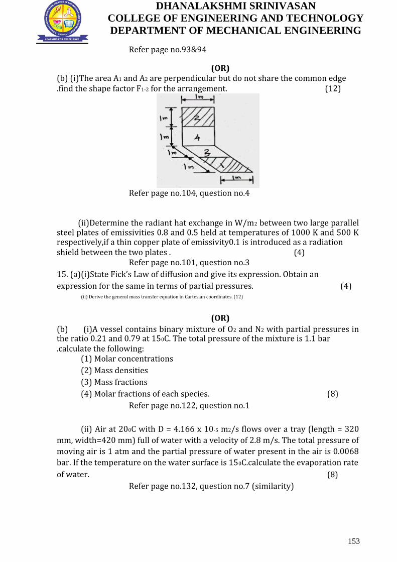
DHANALAKSHMI SRINIVASAN
COLLEGE OF ENGINEERING AND TECHNOLOGY
DEPARTMENT OF MECHANICAL ENGINEERING
Refer page no.93&94
(OR)
(b) (i)The area A1 and A2 are perpendicular but do not share the common edge
.find the shape factor F1-2 for the arrangement. (12)
Refer page no.104, question no.4
(ii)Determine the radiant hat exchange in W/m2 between two large parallel steel plates of emissivities 0.8 and 0.5 held at temperatures of 1000 K and 500 K respectively,if a thin copper plate of emissivity0.1 is introduced as a radiation
shield between the two plates . (4)
Refer page no.101, question no.3
15. (a)(i)State Fick’s Law of diffusion and give its expression. Obtain an
expression for the same in terms of partial pressures. (4)
(ii) Derive the general mass transfer equation in Cartesian coordinates. (12)
(OR)
(b) (i)A vessel contains binary mixture of O2 and N2 with partial pressures in the ratio 0.21 and 0.79 at 150C. The total pressure of the mixture is 1.1 bar .calculate the following:
(1) Molar concentrations (2) Mass densities (3) Mass fractions
(4) Molar fractions of each species. (8)
Refer page no.122, question no.1
(ii) Air at 200C with D = 4.166 x 10⁻⁵ m2/s flows over a tray (length = 320
mm, width=420 mm) full of water with a velocity of 2.8 m/s. The total pressure of
moving air is 1 atm and the partial pressure of water present in the air is 0.0068
bar. If the temperature on the water surface is 150C.calculate the evaporation rate
of water.
(8)
Refer page no.132, question no.7 (similarity)
153

DHANALAKSHMI SRINIVASAN
COLLEGE OF ENGINEERING AND TECHNOLOGY
DEPARTMENT OF MECHANICAL ENGINEERING
B.E/B.Tech DEGREE EXAMINATION, NOVEMBER/DECEMBER 2015.
Fifth Semester
Mechanical Engineering
ME 6502 – HEAT AND MASS TRANSFER
(Regulation 2013)
Time: Three hours
Maximum: 100 marks Answer ALL questions
PART A – (10 x 2= 20 marks)
1. Will the thermal contact resistance be greater for smoother or rough plain surfaces? Why?
2. Distinguish between fin efficiency and its effectiveness.
3. What is Dittus-Boetler equation? When does it apply? Refer page no.39, question no.12
4. Define Grashof number and explain its significance in free convection
heat transfer. Refer page no.36, question no.4 5. What is meant by sub-cooled and saturated boiling?
6. What advantages does the NTU method have over the LMTD method? Refer page no.65, question no.6
7. Define irradiation and radiosity. Refer page no.92, question no.5
8. What is the greenhouse effect? Why is it a matter of great concern among atmospheric scientists?
9. What is the driving force for a) Heat transfer and b) Mass transfer
10. Define Lewis number and state its physical significance
PART B– (5 x 16= 80 marks)
11. (a) (i)Consider a 1.2 m high and 2 m wide double–pane window consisting
of two 3mm thick layer of glass (k=0.78W/mK) separated by a 12mm
wide stagnant air space (k=0.026 W/mK) .Determine the steady rate of
heat transfer through this double –pane window and the temperature of
its inner surface when the room is maintained at 240C while the
temperature of the outdoors is -50C.Take the convective heat
transfer coefficients on the inner and outer surfaces the window to be 10
W/m2K and 25 W/m2K respectively. (8)
154
DHANALAKSHMI SRINIVASAN
COLLEGE OF ENGINEERING AND TECHNOLOGY
DEPARTMENT OF MECHANICAL ENGINEERING
Similar problem Refer page no.16, question no.3
(ii) Derive the general 3-Dimensional heat conduction equation in
Cartesian coordinates. Refer page no.12, question no.1 (8)
(OR)
(b) A cylinder 1m long and 5 cm in diameter is placed in an atmosphere at 450C .It is provided with 10 longitudinal straight fins of materials having k=120 W/mK. The height of 0.76 mm thick fins is 1.27 cm from the cylinder surface. The heat transfer coefficient between cylinder and atmospheric at the end of fins if surface temperature of cylinders is 1500C. (16)
12. (a) (i) A long 10 cm diameter steam pipe whose external surface
temperature is 1100C passes through some open area that is not protected
against the winds. Determine the rate of heat loss from the pipe per unit
length when the air is at 1 atm and 100C and the wind is blowing
across the pipe at a velocity of 8 m/s. (8)
Similar problem Refer page no.52, question no.6
(ii) An air stream at ooc is flowing along a heated plate 900C at a speed of 75 m/s. The plate is 45 cm long and 60 cm wide. Calculate the average values of friction coefficient for the full length of the plate. Also
calculate the rate of energy dissipation from the plate. (8)
Similar problem Refer page no.38, question no.2
(OR)
(b) (i)Explain the concept of Hydrodynamic and thermal boundary
layers. (6)
Refer page no.48, question no.5
(ii)A 6 m long section of an 8 cm diameter horizontal hot water pipe
passes through a large room whose temperature is 200C .If the outer
surface temperature and emissivity of the pipe are 700C and 0.8
respectively, Determine the rate of heat loss from the pipe by (1) Natural
convection
(2) Radiation. (10)
13. (a) Water is boiled at atmospheric Pressure by horizontal polished copper heating element of diameter D= 5 mm and emissivity 0.05 immersed in
water .If the surface temperature of the heating wire is 3500C,determine
the rate of heat transfer from the wire to the water per unit length of the
wire. (16)
(OR)
(b)Hot oil (Cp = 2200 J/kg K) is to cooled by water (Cp = 4180 J/kg K) in a 2 – shell – pass and 12 – tube – pass heat exchanger. The tubes are thin – walled and are made of copper with diameter of 1.8 cm. The length of each
155
DHANALAKSHMI SRINIVASAN
COLLEGE OF ENGINEERING AND TECHNOLOGY
DEPARTMENT OF MECHANICAL ENGINEERING
tube pass in the heat exchanger is 3 m, and the overall heat transfer coefficient is 340 W/m2K.Water flows through the tubes at a total rate of 0.1 kg/s, and the oil through the shell at a rate of 0.2 kg/s. The water and the oil enter at temperature 180C and 1600C ,respectively. Determine the rate of heat transfer in the heat exchanger and the outlet temperatures of
the water and the oil. (16)
Similar problem Refer page no.76, question no.6
14.(a)(i)Two very large parallel plates are maintained at uniform temperatures
of T1=1000 K and T2 = 800 K and have emissivities of ɛ1=ɛ2=0.2 ,respectively. It is
desired to reduce the net radiation heat transfer between the two plates to one-
fifth by placing thin aluminium sheets with an emissivity of 0.15 on both sides
between the plates. Determine the number of sheets that need to be
inserted
(10)
Similar problem Refer page no.101, question no.3
(ii)Define the following terms:
(1) Monochromatic emissivity (2) Gray body
(3) Shape factor. (6)
Refer page no. 93,94
(OR)
(b)(i) The spectral emissivity function of an opaque surface at 1000 K is approximated as
ɛλ1= 0.4,0≤λ<2µm;
ɛλ2= 0.7,2 µm ≤λ<6µm
ɛλ3= 0.3,6 µm ≤λ<∞
Determine the average emissivity of the surface and the rate of radiation
emission from the surface, in W/m2 (8)
Refer page no.104, question no.7
(ii) Emissivities of two large parallel plates maintained at 8000C and 3000C are 0.3 and 0.5 respectively. Find the net radiant heat exchange per
square meter for these plates? (8)
Similar problem Refer page no.101, question no.3
15. (a) (i) A 3-cm-diameter Stefan-tube is used to measure the binary diffusion
coefficient of water vapour in air at 200C at an elevation of 1600 m where the
atmospheric is 8.5 kPa. The tube is partially filled with water, and the distance
from the water surface to the open end of the tube is 40 cm .Dry air is blown a
over the open end of the tube so that water vapour rising to the top is removed
immediately and the concentration of vapour at the top of the tube is zero. In 15
days of continuous –operation at constant pressure and temperature, the amount
156

DHANALAKSHMI SRINIVASAN
COLLEGE OF ENGINEERING AND TECHNOLOGY
DEPARTMENT OF MECHANICAL ENGINEERING
of water that has evaporated is measured to be 1.23 g. Determine the diffusion
coefficient of water vapour in air at 200C and 83.5 kPa. (10)
(ii) State some analogies between heat and mass transfer. (6)
Refer page no.129, question no.5
(OR)
(b)(i) A thin plastic membrane separates hydrogen from air. the molar concentrations of hydrogen in the membrane at the inner and outer surface are determined to be 0.045 and 0.002 k mole/m3, respectively .the binary diffusion coefficient of hydrogen in plastic at the operation temperature is 5.3 x 10⁻¹⁰ m2/s.Determine the mass flow rate of hydrogen by diffusion through the membrane under steady conditions if the thickness of the membrane is
(1) 2 mm and
(2) 0.5 mm.
(8)
Similar problem Refer page no.127, question no.4
(ii) Dry air at 150C and 92 kPa flows over a 2 m long wet surface with a free
stream velocity of 4 m/s. Determine the average mass transfer coefficient.
(8)
157

DHANALAKSHMI SRINIVASAN
COLLEGE OF ENGINEERING AND TECHNOLOGY
DEPARTMENT OF MECHANICAL ENGINEERING
B.E/B.Tech DEGREE EXAMINATION, APRIL/MAY 2015. Fifth Semester
Mechanical Engineering
ME 2251 – HEAT AND MASS TRANSFER
(Regulation 2008)
Time: Three hours Maximum: 100 marks
Answer ALL questions
PART A – (10 x 2= 20 marks)
1. What is meant by transient heat conduction? 2. What is thermal diffusivity?
3. Define velocity boundary layer thickness
Refer page no. 36, Question no.5
4. Distinguish between laminar and turbulent flow Refer page no. 35, Question no.2
5. How heat exchangers are classified?
Refer page no. 65, Question no.5
6. Discuss the advantage of NTU method over the LMTD method. Refer page no. 64, Question no.2
7. State Kirchhoff’s law? Refer page no. 91, Question no.3
8. Define Radiosity Refer page no.92, Question no.5
9. State Fick’s law of diffusion. Refer
page no. 119, Question no.7
10. Define molar concentration. Refer page no. 121, Question no.13
Part –B (5X16=80 Marks)
11.(a) (i) Differentiate between conductivity and conductance. (4)
(ii) A steel pipe line (thermal conductivity K = 50 W/mK) of inner diameter 100 mm and outer diameter 110mm is to be covered with two layers of insulation each having a thickness of 50mm. the thermal conductivity of the first insulation material is 0.06 W/mK and that of the second is 0.12 W/mK. Calculate the loss of heat per meter length of pipe and the interface temperature between the two layers of insulation when the temperature of the inside tube surface is 250o C and that of the outside
surface of the insulation is 50o C. (12)
Refer page no. 20, Question no.5
(OR)
158

DHANALAKSHMI SRINIVASAN
COLLEGE OF ENGINEERING AND TECHNOLOGY
DEPARTMENT OF MECHANICAL ENGINEERING
(b)(i)With a neat sketch, explain different types of fin profile. (4)
(ii) A metallic sphere of radius 10mm is initially at a uniform temperature of 400o C. it is heat treated by first cooling it in air (heat transfer coefficient h = 10 W/m2K at 20o C until its central temperature reaches 335oC to 50o C. Compute the time required for cooling in air and water for the following physical properties of the sphere density = 3000 Kg/m3 specific heat = 1000 J/Kg K: thermal conductivity = 20 W/mK
thermal diffusivity = 6.66 X 10⁻⁶ m2/s. (12)
Refer page no. 27, Question no.9
12.(a) (i)Explain the velocity boundary layer profile on a flat plate and
mentions its significance (4)
Refer page no. 48, Question no.5
(ii)Engine oil at 20oC is forced over a 20 cm square plate at a velocity of 1.2 m/s. The plate is heated to a uniform temperature of 60oC.
Calculate the heat loss of the plate. (12)
(OR)
(b) (i)Considering a heated vertical plate in quiescent fluid, draw the
velocity and temperature profile. (4)
Refer page no. 48, Question no.5
(ii) Water at 60oC enters a tube of 2.54 mm diameter at a mean flow velocity of 2 cm/s. Calculate the exit water temperature if the tube is 3 m long and the wall temperature is constant at 80oC. (12)
13.(a) (i) with a neat sketch explain various regimes of pool boiling. (4)
Refer page no. 68, Question no.1
(ii) A 10 X 10 array of horizontal tubes of 1.27 cm diameter is exposed to
pure steam at atmospheric pressure. If the tube wall temperature is 980 C,
estimate the mass of steam condensed assuming a tube length of 1.5 m.
(12)
(OR)
(b) (i) What are the different type of fouling in heat exchangers? (4)
(ii) Water enters a cross flow heat exchanger (both fluid unmixed) at 5o C and flows at the rate of 4600 kg/h to cool 4000 kg/h of air that is
initially at 40o C. assume the overall heat transfer coefficient value to be 150 W/m2K. For an exchanger surface area of 25 m2. Calculate the exit
temperature of air and water. (12)
14.(a) Consider a cylindrical furnace with outer radius = 1 m and height = 1 m the top (surface 1) and the base (surface 2) of the furnace have emissivities 0.8 & 0.4 and are maintained at uniform temperatures of 700 K and 500K respectively. The side surface closely approximates a black body and is maintained at a temperature of 400 K. Find the net rate of radiation heat transfer at each surface during steady state operation.
(16)
Refer page no.108, Question no.6
159

DHANALAKSHMI SRINIVASAN
COLLEGE OF ENGINEERING AND TECHNOLOGY
DEPARTMENT OF MECHANICAL ENGINEERING
(OR)
(b) Emissivities of two large parallel plates maintained at 800oC and 300o C are 0.3 and 0.5 respectively. Find the net radiant heat exchange per square meter for these plates. Find the percentage reduction in heat transfer when a polished aluminium radiations shield (€ = 0.05) is placed
between them. Also find the temperature of shield. (16)
Refer page no.101, Question no.3
15. (a) Dry air at 27o C and 1bar flows over a wet plate of 50 cm at 50 m/s. Calculate the mass transfer coefficient of water vapour in air at the end
of the plate. Refer page no.126, Question no.3 (16)
(OR)
(b) (i) What are the assumptions made in the 1 – D Transient mass
diffusion problems? (4)
(ii) The dry bulb and wet bulb temperatures recorded by a thermometer in moist air are 27oC and 17o C respectively. Determine the specific humidity of air assuming the following values: Prandtl number= 0.74 Schmidt number = 0.6 specific heat at constant pressure
= 1.004KJ/Kg K, pressure = 1.0132 X 10⁵ N/m2. (12)
160

DHANALAKSHMI SRINIVASAN
COLLEGE OF ENGINEERING AND TECHNOLOGY
DEPARTMENT OF MECHANICAL ENGINEERING
B.E/B.Tech. DEGREE EXAMINATION, NOVEMBER/DECEMBER 2014.
Fourth Semester
Mechanical Engineering
ME 2251 – HEAT AND MASS TRANSFER
(Regulation 2008)
Answer ALL questions. PART A – (10 X 2 = 20 marks)
1. State Fourier’s Law of conduction. Refer Page No.09 Question No.01
2. What is meant by lumped heat capacity
analysis? Refer Page No.11 Question No.08
3. Name four dimensions used for dimensional analysis. Refer Page No.39 Question No.10
4. Define Grashof Number. Refer Page No.36 Question No.04
5. What is pool boiling? Give an example for
it. Refer Page No.66 Question No.08
6. What is meant by effectiveness?
Refer Page No.66 Question No.10
7. What are the factors involved in radiation by a body? Refer Page No.92 Question No.06
8. What is the use of radiation shield?
Refer Page No.92 Question No.04 9. State Fick’s law diffusion.
Refer Page No.119 Question No.07
10. List out the various modes of mass transfer. Refer Page No.119 Question No.03
PART B-(5 16=80 marks)
11. (a) (i) Derive general heat conduction equation in Cartesian coordinates.
Refer Page No.12 Question No.01 (10)
(ii) Compute the heat loss per square meter surface area of a 40 cm thick furnace wall having surface temperatures of 3000C and 500C if the thermal conductivity k of wall material is given by k=0.005T 5 10-6T2 where
T=temperature in 0C. (6)
(Or)
161

DHANALAKSHMI SRINIVASAN
COLLEGE OF ENGINEERING AND TECHNOLOGY
DEPARTMENT OF MECHANICAL ENGINEERING
(b) (i) A furnace wall consists of 200mm layer of refractory bricks,6 mm layer of steel plate and 100 mm layer of insulation bricks. The maximum temperature of the wall is 11500C on the furnace side and the minimum temperature is 400C on the outermost side of the wall. An accurate energy balance over the furnace shows that the heat loss from wall is 400 W/m2. It is known that there is a thin layer of air between the layers of refractory bricks and steel plate. Thermal
conductivities for the three layers are 1.52, 45 and 0.138W/m0C respectively.
Find
(1) To how many millimetres of insulation brick is the air layer equivalent?
(2) What is the temperature of the outer surface of the steel plate? (8)
(ii) Find out the amount of heat transferred through an iron fin of length 50 mm, width 100 mm and thickness 5 mm. Assume k=210 KJ/mh0C and h=42 kJ/mh0C for the material of the fin and the temperature at the base of the fin as 800C . Also determine the temperature at tip of the fin, if atmosphere temperature
is 200C. (8)
Similar Problem Refer Page No.23 Question No.07
12. (a) (i) Explain about velocity boundary layer on a flat plate. (6)
Refer Page No.48 Question No.05
(ii) Assuming that a man can be represented by a cylinder 30 cm in diameter and 1.7 m high with a surface temperature of 300C , calculate the heat he would lose while standing in a 36km/h wind at 100C . (10)
(Or)
(b) (i) A metal plate 0.609 m high forms the vertical wall of an oven and is at a temperature of 1610C . Within the oven air is at a temperature of 93.00C and one atmosphere. Assuming that natural convection conditions hold near the plate, estimate the mean heat transfer coefficient and the rate of heat transfer per unit width of the plate. (8)
(ii) A 10 mm diameter spherical steel ball at 2600C is immersed in air at
900C. Estimate the rate of convective heat loss. (8)
13. (a) A vertical tube of 50 mm outside diameter and 2 m long is exposed to steam at atmospheric pressure. The outer surface of the tube is maintained at a temperature of 840C by circulating cold water through the tube. Determine the
rate of heat transfer and also the condensate mass flow rate. (16)
Similar Problem
(Or)
(b) (i) Explain about Fouling Factors. (4)
Refer Page No.66 Question No.09
(ii) Hot oil with a capacity rate of 2500 W/K flows through a double pipe heat exchanger. It enters at 3600C and leaves at 3000C. Cold fluid enters at 300C and leaves at 2000C. If the overall heat transfer coefficient is 800 W/m2K. Determine the heat exchanger area required for (1) Parallel flow and (2) Counter
flow. (12)
Refer Page No. & 76, Question No.06
14. (a) Calculate the following for an industrial furnace in the form of a black body and emitting radiation at 25000C . (i) Monochromatic emissive power at 1.2
162
DHANALAKSHMI SRINIVASAN
COLLEGE OF ENGINEERING AND TECHNOLOGY
DEPARTMENT OF MECHANICAL ENGINEERING
m length. (ii) Wave length at which the emission is maximum. (iii) maximum emissive power (iv) Total emissive power and (v) Total emissive power of the
furnace if it is assumed as a real surface with emissivity equal to 0.9. (16) Refer Page No.95 Question No.01
(Or)
(b) Two parallel plates of size 1.0 m by 1.0 m spaced 0.5 m apart are located in a very large room, the walls of which are maintained at temperature of 270C. One plate is maintained at a temperature of 9000C and the other at 4000C. Their emissivities are 0.2 and 0.5 respectively. If the plates exchange heat between themselves and surroundings, find the net heat transfer to each plate and to the
room. Consider only the plate surfaces facing each other. (16)
Refer Page No.96 Question No.02
15. (a) (i) Discuss about steady state equimolar counter diffusion. (8)
Refer Page No.130 Question No.06
(ii) Hydrogen gas is maintained at pressures of 2.4 bar and 1 bar on opposite sides of a plastic membrane 0.3 mm thick. The binary diffusion coefficient of hydrogen in the plastic is 8.6 x 10⁻⁸ m2/s and solubility of hydrogen in the membrane is 0.00145 kg mole/m3-bar. Calculate, under uniform temperature conditions of 240C the following (1) Molar concentrations of the membrane and (2) Molar and mass diffusion flux of hydrogen through the membrane. (8)
(Or)
(b) (i) Air at 200C ( ρ = 1.205 kg/m3, ν = 15.06 x 10⁻⁶ m2/s, D = 4.166 x 10⁻⁵ m2/s), flows over a tray (length = 320 mm, width = 420 mm) full of water with velocity of 2.8m/s. The total pressure of moving air is 1 atm and the partial pressure of water present in the air is 0.0068 bar. If the temperature on the water surface is 150C, calculate the evaporation rate of water. (8)
Similar problem Refer Page No.132 Question No.07
(ii) Dry air at 270C and 1 atm flows over a wet flat plate 50cm long at a
velocity of 50m/s. Calculate the mass transfer coefficient of water vapour in air at
the end of the plate. (8)
Refer Page No.126 Question No.03
163

DHANALAKSHMI SRINIVASAN
COLLEGE OF ENGINEERING AND TECHNOLOGY
DEPARTMENT OF MECHANICAL ENGINEERING
B.E/B.Tech DEGREE EXAMINATION, APRIL/MAY_2014.
Fifth Semester
Mechanical Engineering
ME 2251 – HEAT AND MASS TRANSFER
(Regulation 2008)
Time: Three hours
Maximum: 100 marks Answer ALL questions
PART A – (10 x 2= 20 marks)
1. Write any two examples of heat conduction with heat generation.
2. Define critical thickness of insulation with its significance. Refer page no: 10, Q.No. 7
3. Differentiate viscous sub layer and buffer
layer. Refer page no. 35, Q. No 3
4. Define grashoff number and prandtl number. Refer page no. 36, Q. No 4
5. What are the different regimes involved in pool
boiling. Refer page no. 58, Q. No 3
6. Write down the relation for overall heat coefficient in heat exchanger with fouling factor. Refer page no. 65, Q. No 4
7. Define irradiation and emissive power.
Refer page no. 92&93, Q. No 5 & 10
8. Write down any two shape factor algebra. 9. State fick’s law of diffusion.
Refer page no.119, Q. No 7 10. Write down the analogous terms in heat and mass transfer.
Part –B (5X16=80 Marks)
11. (a) Drive the general heat conduction equation in cylindrical coordinate
and solve the following. (8)
Refer page no. 14, Q. No 1
Hot air at a temperature of 650C is flowing through steel pipe of 120 mm diameter. The pipe is covered with tow layer of different insulating
164

DHANALAKSHMI SRINIVASAN
COLLEGE OF ENGINEERING AND TECHNOLOGY
DEPARTMENT OF MECHANICAL ENGINEERING
material of thickness 60mm and 40mm, and their corresponding thermal
conductivities are 0.24 and 0.4W/m2K. The inside and outside heat transfer
coefficients are 60 W/m2K and 12 W/m2K respectively. The atmosphere is
at 200C. Find the rate of heat loss from 60 m length of pipe.
Refer page no.20, Q. No 5 (similar) (8)
(OR)
(b) Drive the heat dissipation equation through pin fin with insulated end
and solve the following. (8) A temperature rise of 500C in
a circular shaft of 50 mm diameter is caused by the amount of heat
generated due to friction in the bearing mounted on the crankshaft. The
thermal conductivity of shaft material is 55 W/mK and heat transfer
coefficients is 7 W/m2K.Determind the amount of heat transferred through
shaft assume that the shaft is a rod of infinite
length. (8)
12. (a) Using dimensional analysis find dimensionless groups involved in free convection any solved the following.
A horizontal heated plate measuring 1.5m x 1.1m and at 2150C, facing upwards is placed in still air at 250C. Calculate the heat loss by natural
convection. Use the relation
H=3.05(Tf)1/4, Tf = Mean film temperature. (16)
(OR)
(b) Explain development of hydrodynamic and thermal boundary layers with suitable figure and solve the following Refer page no.45, Q. No 5
In a straight tube of 50mm diameter, water is flowing at 15m/s. The tube
surface temperature is maintained at 600C and the flowing water is heated
from the inlet temperature 150C to an outlet temperature of 450C calculate
the heat transfer coefficient from the tube surface to the water and length
of the tube. (16)
13. (a) Explain nucleate boiling and solve the following. Refer page no.68, Q. No 1
A wire of 1mm diameter and 150mm length is submerged horizontally in water at 1 bar. The wire carries a current of 131.5 ampere with an applied
voltage of 2.15 volt. If the surface of the wire is maintained at 1800C,
calculate the heat flux and the boiling heat transfer coefficient. (16) Refer page no.72, Q. No 3
(OR)
(b) Classify the heat exchangers, draw temperature distribution in a condenser and evaporator and derive the expression for effectiveness of
parallel flow heat exchanger by NTU method. (16)
Refer page no.80, Q. No 9
14. (a) State laws of radiation and solve the following
165

DHANALAKSHMI SRINIVASAN
COLLEGE OF ENGINEERING AND TECHNOLOGY
DEPARTMENT OF MECHANICAL ENGINEERING
Assuming the sun to be black emitting radiation with maximum intensity at λ=0.5µm, calculate the surface temperature of the sun and heat flux at its
surface. (16)
(OR)
(b) Derive the relation for heat exchange between infinite parallel planes and solve. Refer page no.113, Q. No 9 Consider double wall as two infinite parallel planes. The emissivity of the
walls is 0.3 and 0.8 respectively. The space between the walls is evacuated.
Find the heat transfer/unit area when inner and outer surface
temperatures are 300K and 260K. To reduce the heat flow, a shield of
polished aluminium with ε=0.05 is inserted between the walls. Find the
reduction in heat transfer. (16)
Refer page no.96, Q. No 2 (similar problem)
15. (a) Explain different modes of mass transfer and derive the general mass
diffusion equation in stationary media. (16)
(OR)
(a) Explain Reynold’s number, Sherwood number, Schmidt number and solve the following. A vessel contains a binary mixture of oxygen and nitrogen with partial
pressures in the ratio 0.21 and 0.79 at 150C. The total pressure of the
mixture is 1.1 bar. Calculate the following i. Molar concentrations (4)
ii. Mass densities(4) iii. Mass fractions(4) iv. Molar fractions of each species. (4)
Refer page no.122, Q. No 1
166

DHANALAKSHMI SRINIVASAN
COLLEGE OF ENGINEERING AND TECHNOLOGY
DEPARTMENT OF MECHANICAL ENGINEERING
B.E/B.Tech. DEGREE EXAMINATION, NOVEMBER/DECEMBER 2013. Fourth Semester
Mechanical Engineering
ME 2251 – HEAT AND MASS TRANSFER
(Regulation 2008)
Answer ALL questions.
PART A – (10 X 2 = 20 marks)
1. Define Fourier’s law of conduction. Refer Page No.9, Question No.1 2. A plane wall 10 cm thick generates heat at the rate of4 x 104w/m3 when an electric current passed through it. The convective heat transfer coefficient between each face of the wall and ambient air 50 w/m2k.Determine the surface temperature Assume the air temperature to be 20oc and k(for wall)=15 w/mk. 3. Define the term thermal boundary layer.
4. Why heat transfer coefficient for natural convection is much lesser than that for forced convection? Refer Page No.38, Question No.9 5. Distinguish the pool boiling from forced convection boiling.
6. What are limitations of LMTD method? How is ε-NTU method superior to LMTD method? Refer Page No.65, Question No.6 7. State Planck’s law?
8. How radiation from gases differs from solids? Refer Page No.92, Question No.8 9. Write general mass diffusion equation. 10. Define Schmidt and Lewis numbers. What is the physical significance of each? Refer Page No.120, Question No.10
Part –B (5X16=80 Marks)
11. a) The door of an industrial furnace is 2m x 4m in surface area and is to be insulated to reduce the heat loss to not more than 1200 W/m2.The interior and exterior walls of the door are 10 mm and 7mm thick steels (k= 25 w/m2k). Between these two sheets , a suitable thickness of insulation material is to be placed. The effective gas temperature inside the furnace is 1200oc and the overall
heat transfer coefficient between the gas and door is 20 w/m2k.The heat transfer coefficient outside the door is 5 w/m2oc.The surrounding air
temperature is 20oc.Select suitable insulation material and its size. (16)
(Or)
167

DHANALAKSHMI SRINIVASAN
COLLEGE OF ENGINEERING AND TECHNOLOGY
DEPARTMENT OF MECHANICAL ENGINEERING
b) (i) A turbine blade 6 cm long and having a cross-sectional area 4.65 cm2 and parameter 12 cm is made of stainless steel (k= 23.3 w/m k).The temperature at the root is 500oc.The blade is exposed to a hot gas at 870oc.The heat transfer coefficient between blade surface and gas is 442 w/m2 k .Determine the temperature distribution and rate of heat flow at the root of the blade. Assume
the tip of the blade to be insulated. (8)
ii) An ordinary egg can be approximated as a 5 cm diameter sphere. The egg is initially at a uniform temperature of 5oc and is dropped into boiling water at 95oc.Taking the convection heat transfer coefficient to be h = 200 w/m2oc,
determine how long it will take for the centre of the egg to reach 70oc. (8)
Refer similar problem Page No. 27, Question No. 9
12. a) i) Explain in detail about boundary layer concept (6)
Refer similar problem Page No. 48, Question No. 5
ii) An aeroplane flies with a speed of 450 km/h at a height where the surrounding air has a temperature of 1oc and pressure of 65 cm of Hg. The aeroplane wing idealized as a flat plate 6m long ,1.2 m wide is maintained at 19oc.If the flow is made parallel to the 1.2 m width calculate: (1) Heat loss from
the wing; (2) Drag force on the wing. (10)
(Or)
b) A two stroke motor cycle petrol engine cylinder consists of 15 annular fins. If outside and inside diameters of each fin are 200 mm and 100mm respectively. The average fin surface temperature is 475oc and they are exposed in air at 25oc.Calculate the heat transfer rate from the fins for the following condition (i) When motor cycle is at rest (ii)when motor cycle is running at a speed of 60 km/h. The fin may be idealized as a single horizontal flat plate of same area. (16)
13. a) i) Explain the various regions of flow boiling in detail (6)
Refer similar Page No. 68, Question No. 1
ii) The outer surface of a vertical tube which is 6m long and has an outer diameter of 80 mm, is exposed to saturated steam at atmospheric pressure and is maintained at 50oc by the flow of cool water through the tube. What is the rate of heat transfer to coolant and what is the rate at which steam is condensed at the surface? (10)
(Or)
b) A Counter -Flow Concentric Tube Heat Exchanger Is Used To Cool the lubricating oil for a large industrial gas turbine engine. The flow rate of cooling water through the inner tube (di=20mm) is 0.18 kg/s while the flow rate of oil
through the outer annular (do=40mm)is 0.12 kg/s. The inlet and outlet temperatures of an are 95oc and 65oc respectively. The water enters at 30oc to the exchanger Neglecting tube wall thermal resistance, fouling factors and heat loss to the surroundings, Calculate the length of the tube . Take the following properties at the bulk mean temperature:
Engine oil at 80oc, CP =2131 J/Kgoc , µ =0.0325 N-sm2; k =0.138w/moc;
168

DHANALAKSHMI SRINIVASAN
COLLEGE OF ENGINEERING AND TECHNOLOGY
DEPARTMENT OF MECHANICAL ENGINEERING
water at 35oc; CP =4174 J/Kgoc , µ =725x103 N-sm2; k =0.625w/moc ,Pr =4.85 (16) Refer similar problem Page No. 75, Question No. 5
14 a) i) A Truncated cone has top and bottom diameters of 10 and 20 cm and a height of 10cm .Calculate the shape factor between the top surface and the side
and also the shape factor between the side and itself. (10)
Ii) Emissivities of two large parallel plates maintained at 800oc and 300oc and0.3and0.5 respectively. Find the net radiant heat exchange per square meter
for these places. (6)
(Or)
b) A 12 mm outside diameter pipe carries a cryogenic fluid at 90 k. Another pipe of 15 mm outside diameter and 290k surrounds it coaxially and the space between the pipes is completely (i) determine the radiant heat flow for 3.5 m length of pipe if the surface emissivity for both surface is 0.25 (ii) Calculate the percentage reduction in heat flow if a shield of 13.5 mm diameter and 0.06
surface emissivity is placed between pipes. (16)
15 a) Air is contained in a tyre tube of surface area 0.5m2 and wall thickness 10
mm. The pressure of air drops from 2.2 bar and 2.18 bar in a period of 6 days. The solubility of air in the rubber is0.072m3 of air per m3 of rubber at 1 bar. Determine the diffusivity of air in rubber at the operating temperature of 300k if
the volume of air in the tube is 0.028m3. (16)
(Or)
b) Air at 35oc and 1 atmospheric flows at a velocity of 60 m/s over (i) a flat plate 0.5m long (ii) a sphere 5 cm in diameter. Calculate the mass transfer coefficient of water in air. Neglect the concentration of vapour in air. (16)
Refer similar problem Page No. 126, Question No. 3 ( similarity)
169
DHANALAKSHMI SRINIVASAN
COLLEGE OF ENGINEERING AND TECHNOLOGY
DEPARTMENT OF MECHANICAL ENGINEERING
170


![Dhanalakshmi Project[1]](https://static.fdocuments.in/doc/165x107/550055ad4a7959da6c8b50dd/dhanalakshmi-project1.jpg)