
HMI DISPLAY INSTALLATION - Kele Network_and_Wireless/PDFs/HMI DISPLAY... · HMI display...
16
HMI display Installation Guide • Product Description • Specifications • Important Information o Package Contents o Related Documents o Accessories • Cautions and Warnings • Mounting and Dimensions o BAC-DIS-ENC Direct Surface Mount (drywall, sheet metal) Direct Surface Mount (existing single or multi-gang box) Through Hole Panel Mount o BAC-DIS-ENC Surface Mount (with conduit) Drywall Flush Mount (new construction) Drywall Flush Mount (retrofit) • Board Layout • General Wiring • Power • Network Communication • Appendix A - Through Hole Panel Mount • Appendix B - BAC-DIS-ENC Dimensions
Transcript of HMI DISPLAY INSTALLATION - Kele Network_and_Wireless/PDFs/HMI DISPLAY... · HMI display...

HMI display Installation Guide • Product Description • Specifications • Important Information
o Package Contents o Related Documents o Accessories
• Cautions and Warnings • Mounting and Dimensions
o BAC-DIS-ENC Direct Surface Mount (drywall, sheet metal) Direct Surface Mount (existing single or multi-gang box) Through Hole Panel Mount
o BAC-DIS-ENC Surface Mount (with conduit) Drywall Flush Mount (new construction) Drywall Flush Mount (retrofit)
• Board Layout • General Wiring • Power • Network Communication • Appendix A - Through Hole Panel Mount • Appendix B - BAC-DIS-ENC Dimensions

Product Description
The HMI display is a seven-inch wide-screen format LCD touch display unit used for interfacing with a BACnet building automation system. The HMI display uses BACnet over Ethernet or BACnet/IP to communicate with the controllers on a local area network using real-time graphics.
The HMI display can be wall or panel mounted in mechanical rooms which allows for monitoring and setting schedules for air handlers, boilers, chillers and other mechanical equipment.
It is also designed to be mounted in public spaces. The HMI display can be used as a small building interface making it easy for occupants to change occupancy schedules, adjust temperature setpoints and view floor layouts.

Specifications
Power • 24VAC 50/60 Hz or 10VDC • Class 2 • Dedicated transformer • Full-wave rectified
Power Consumption • 15.0 VA Max
Ambient Ratings • 32 to 131°F (0 to 55°C) • 10 to 90% RH non
condensing
Communication Ports
Ethernet • 2x 10/100BaseT @ 10/100Mbps
• BACnet IP • BACnet over Ethernet
USB • USB 2.0 Full Speed, (USB Flash Drives)
Inputs Temperature Internal Thermistor (On-Board)
• 10,000 ohm @ 77 ºF (25 ºC)
• Accuracy of +/- 1.44 ºF from 32 - 131 ºF (+/- 0.8 ºC from 0 - 55 ºC)
• Stability of 0.24 ºF over 5 years (0.13 ºC)
• Jumper Selection for Internal or External Thermistor
External Thermistor (Remotely Located)
• Use a standard 10K Thermistor (10,000 ohm @ 77 ºF / 25 ºC)
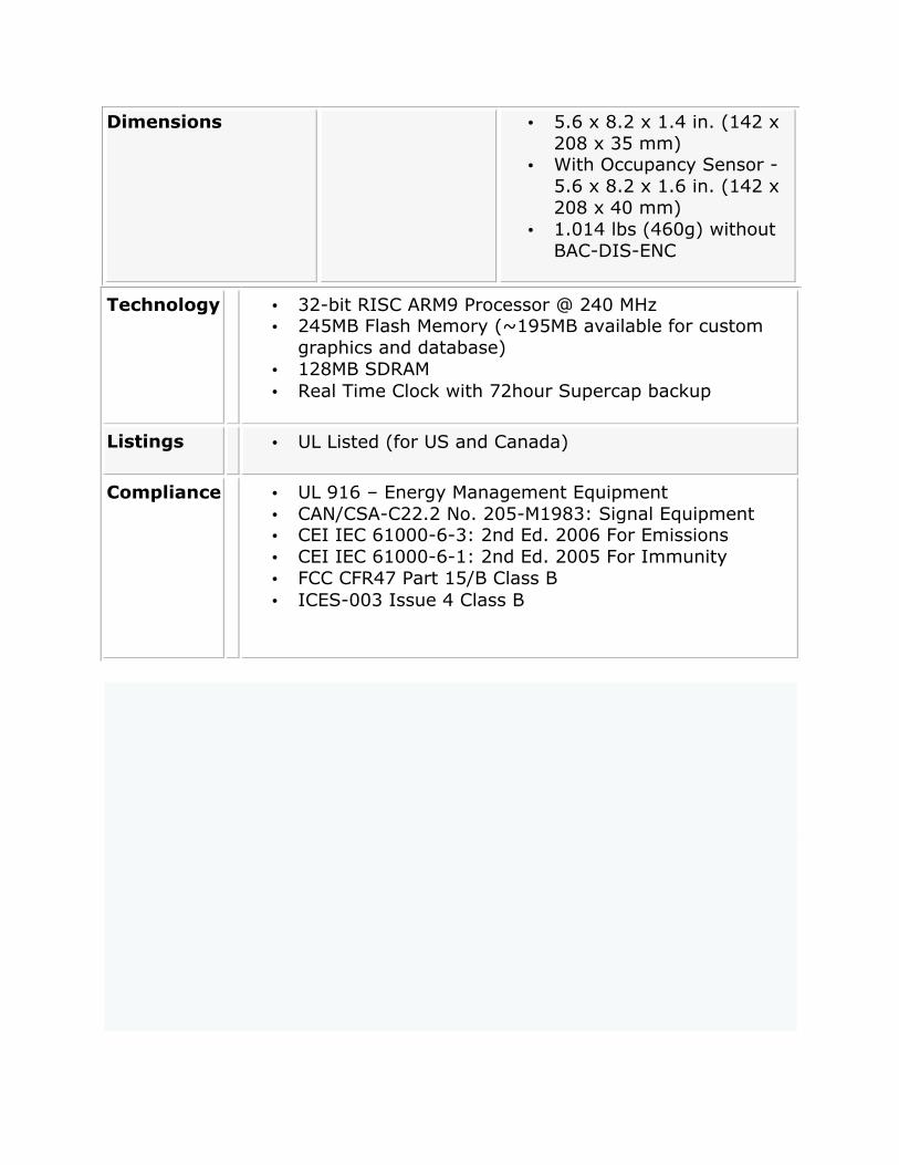
Dimensions • 5.6 x 8.2 x 1.4 in. (142 x 208 x 35 mm)
• With Occupancy Sensor - 5.6 x 8.2 x 1.6 in. (142 x 208 x 40 mm)
• 1.014 lbs (460g) without BAC-DIS-ENC
Technology • 32-bit RISC ARM9 Processor @ 240 MHz • 245MB Flash Memory (~195MB available for custom
graphics and database) • 128MB SDRAM • Real Time Clock with 72hour Supercap backup
Listings • UL Listed (for US and Canada)
Compliance • UL 916 – Energy Management Equipment • CAN/CSA-C22.2 No. 205-M1983: Signal Equipment • CEI IEC 61000-6-3: 2nd Ed. 2006 For Emissions • CEI IEC 61000-6-1: 2nd Ed. 2005 For Immunity • FCC CFR47 Part 15/B Class B • ICES-003 Issue 4 Class B

Important Information
HMI Configurator software BAC-DIS-XXX and controller firmware must all be of the same version number (i.e. 3.33) to be compatible. When upgrading any of these products from older versions (i.e. 3.22 or 3.30), you must upgrade all the remaining products.
Package Contents
• Product: HMI display
Related Documents
• HMI display Operator Guide
Accessories
• BAC-DIS-ENC (includes retrofit clamps) - for surface mounting with conduit or flush wallboard mount (new and retrofit)
Cautions and Warnings
This controller is an Electro-statically sensitive device. Proper ESD protection (ground strap) should be used when installing this product so that damage to the product does not occur.
Equipment damage or loss of data may occur if these procedures are not followed as specified.
Installations requiring CE conformance: All wiring for CE rated products must use an extra low voltage (SELV) or protective extra low voltage (PELV) transformer. Use safety-isolating transformers, (Class II transformer) per EN61558. The transformer must be rated for 100% duty cycle.

Mounting and Dimensions
The HMI display has the following mounting options:
• Direct surface mount • Single or multi-gang box mount • Through hole panel mount
Using the optional BAC-DIS-ENC electrical box allows for additional mounting options:
• Conduit surface mount • New drywall flush mount • Retrofit drywall flush mount
Mounting options without the BAC-DIS-ENC
Figure 1: Dimensions (without BAC-DIS-ENC)

Direct Surface Mount (drywall, sheet metal)
The HMI display is directly mounted to the wall surface, typically sheet metal for a panel door or drywall. This allows for the quickest and easiest installation and does not require the BAC-DIS-ENC. The HMI display will extend approximately 1.4in. (35mm) above the mounting surface.
1. Level the HMI display on the mounting surface. 2. On the surface, mark at least 4 screw holes and the pass through
hole for the power and Ethernet cable. Note: Only use the holes show in Figures 2 and 3, not the holes shown in Figure 4
3. Cut a hole into the surface for the power and Ethernet cable to pass through, and drill screw holes if necessary.
4. Mount the HMI display using screws and wall anchors appropriate for the mounting surface.
Direct Surface Mount (existing single or multi-gang box)
Allows use with pre-installed single or multi-gang electrical boxes. The screw holes in the HMI display back plate line up with North American standard, and European standard electrical boxes.
Figure 2: North American Standard Box Holes
Figure 3: European Standard Box Holes
Single- or Multi-Gang box Mounting Procedure

1. Use the holes on back plate to attach the HMI display to a single or multi-gang box. Use the appropriate holes for either North American or European standard electrical boxes (Figure 2 and Figure 3) Note: For a single or a double-gang box, use at least two wall anchors on the right side of the HMI display.
2. For multi-gang boxes, the Cat5 and power cable pass through hole on the HMI display aligns with the multi gang box furthest to the left.
Through Hole Panel Mount
This method is for a panel door mount when a flush appearance is desired. Once mounted the HMI display extends approximately 0.9 in. (22mm) above the mounting surface.
1. Cut a hole is cut into the surface. See Appendix A for sheet metal cutout specifications.
2. Mount the HMI display by using the 4 outside slotted mounting holes (see Figure 4) on the back of the HMI display. Use screws appropriate for the mounting surface.
Figure 4: Outside Mounting Holes

Mounting Options with the BAC-DIS-ENC
The BAC-DIS-ENC is not included with the HMI display. It is an optional metal electrical box which includes retrofit connectors to allow flush mounting the HMI display in existing drywall.
Figure 5: HMI display with BAC-DIS-ENC
Surface Mount (with conduit)
Mounting on to a surface such as concrete or brick where conduit is used requires the optional BAC-DIS-ENC . ½ and ¾ inch knock-outs for conduit fittings are located on the 4 sides as well as the bottom of the box. See Appendix B for dimensions of just the BAC-DIS-ENC. The HMI display will sit approximately 3.0in. (76mm) above the mounting surface when installed in this manner. The retrofit connectors included with the BAC-DIS-ENC are not required. The HMI display is attached to the BAC-DIS-ENC using the 4 short screws included with the BAC-DIS-ENC.
Drywall Flush Mount (new construction)
With new construction, installation is similar to that of a regular electrical box and does not use the BAC-DIS-ENC retrofit clamps. The BAC-DIS-ENC is attached to a stud prior to drywall installation and positioned such that when the drywall is mounted, it will be flush with the top of the BAC-DIS-ENC. When installed the HMI display sits approximately 0.9in. (22mm) above the drywall. When the wall surface is finished, the HMI display is attached to the BAC-DIS-ENC using 4 short screws (included with the BAC-DIS-ENC).
Drywall Flush Mount (retrofit)
The BAC-DIS-ENC is clamped to the drywall by tightening the 4 retrofit screws on the sides of the BAC-DIS-ENC. The HMI display will sit approximately 0.9in. (22mm) above the drywall.
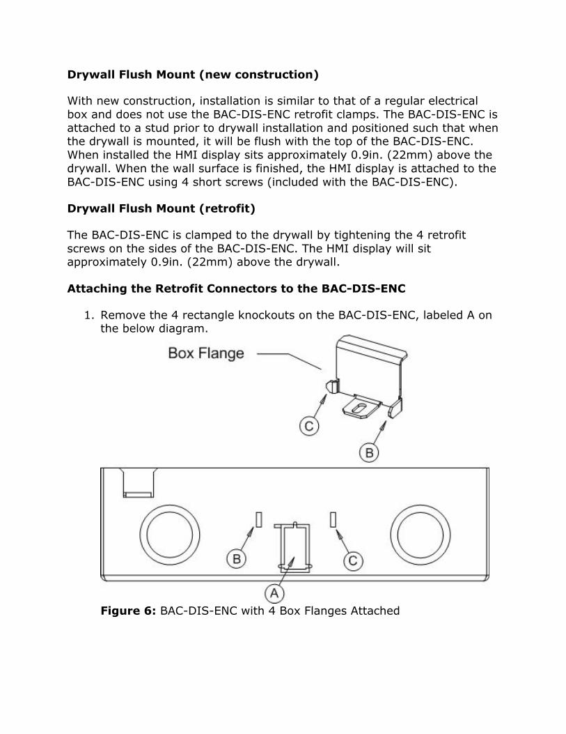
Attaching the Retrofit Connectors to the BAC-DIS-ENC
1. Remove the 4 rectangle knockouts on the BAC-DIS-ENC, labeled A on the below diagram.
Figure 6: BAC-DIS-ENC with 4 Box Flanges Attached

2. Insert Tab C of the Box Flange into Slot C of the BAC-DIS-ENC. Rotate clamp into side of the box so Tab B of the Box Flange is inserted into Slot B of the BAC-DIS-ENC.
3. From the inside of the BAC-DIS-ENC, bend Tab B to the side with a pair of pliers to secure the Box Flange to the BAC-DIS-ENC. Repeat the above steps to attach the three remaining Box Flanges to the BAC-DIS-ENC as shown in Figure 7.
Figure 7: BAC-DIS-ENC with 4 Box Flanges Attached
4. Inside the BAC-DIS-ENC , pass included 1-1/4in. Slotted machine screws through the hole of a Box Flange and into the threads of the Retrofit Clamp. Turn the screw just enough to start the threads into the Retrofit Clamp, so that it can pivot in and out of the rectangular knockout.
Figure 8: Retrofit Clamps Pivoted Inward

5. Repeat for the 3 other clamp locations. Leave the 4 Screw/Retrofit Clamps rotated inside the box. This will allow inserting the BAC-DIS-ENC through the drywall without losing clamps or screws. Mounting the Box
6. Place the BAC-DIS-ENC into the wall, then pivot the 4 bottom clamps out of the box. Tighten each of the 4 screws until the box is clamped to the drywall. Do not over tighten.
Figure 9: Retrofit Clamps Tightened
7. The HMI display is attached to the BAC-DIS-ENC using the 4 3/16in. Phillips machine screws included with the BAC-DIS-ENC

Board Layout
The following Figure 10 shows the HMI display circuit board. This is a view from above, when the unit is opened and mounted on a wall. When closed, the reset button will be on the bottom of the unit.
Figure 10: HMI display PCB Layout (not to scale)

General Wiring
All wiring must conform to NEC and local codes and regulations. Use earth ground isolating step-down Class 2 transformers. Do not use autotransformers. Determine supply transformer rating by summing total VA of product and output loads.
Risk of Electric Shock or Fire
More than one disconnect switch may be required to de-energize the equipment before servicing.
Do not interconnect the outputs of different Class 2 circuits.
All terminals are acceptable for Class 2 Circuit connections only
Use copper conductors only
Apply minimum 4 - 5.5 lb-in torque for tightening field wires into the terminal blocks. Use 22-12 AWG wires.
Power
The HMI display is designed to use a 24VAC Class 2 power supply. The HMI display is a full-wave rectified device, therefore the HMI display requires its own dedicated transformer. The transformer must be properly sized for the total VA requirements.
Network Communication
The HMI display uses BACnet over Ethernet for communications. BACnet IP is support is added with BAC-DIS-ADV.
The two Ethernet ports function as a 10/100 Mbps Ethernet switch, allowing daisy-chaining a second Ethernet HMI display, Ethernet controller or other Ethernet device.
The two Ethernet ports operate at independent speeds.
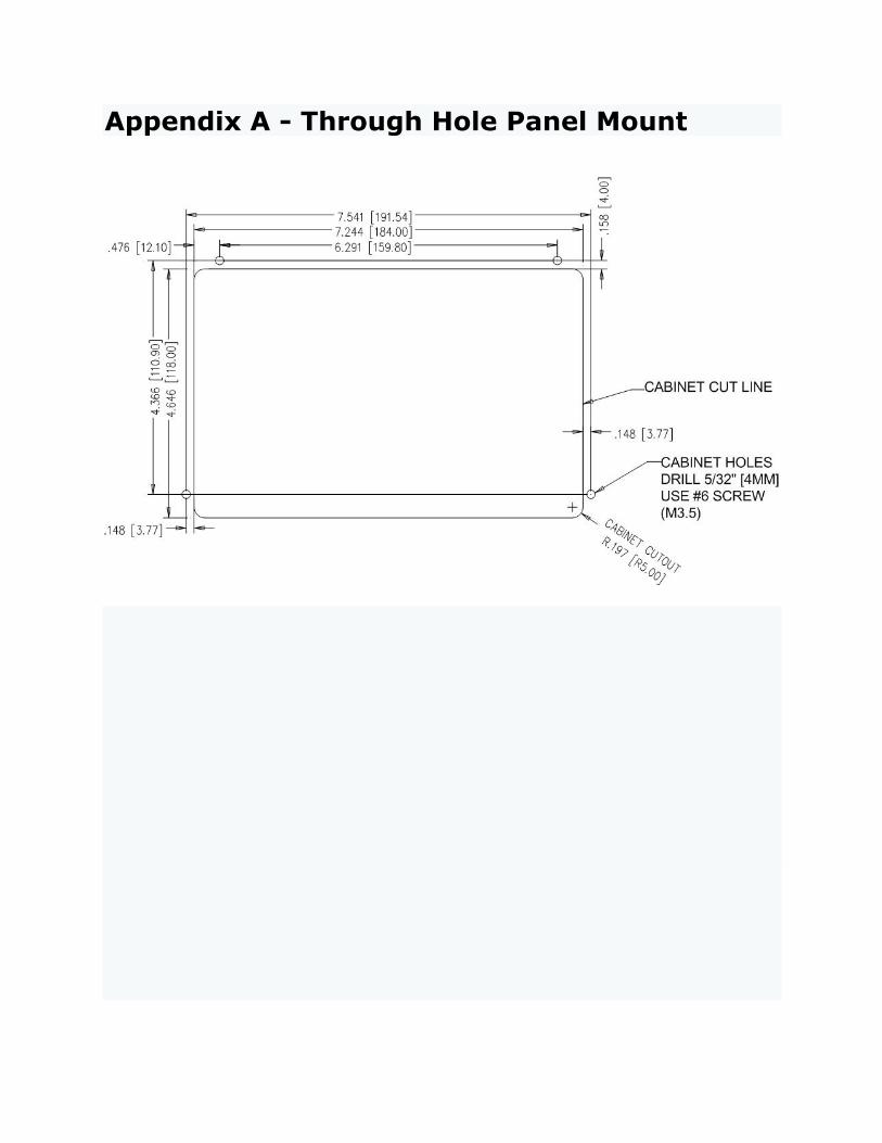
Appendix A - Through Hole Panel Mount

Appendix B - BAC-DIS-ENC Dimensions