HMI connection manual - imservo.com · ii catalog 1 serial port of hmi ..... 1
175
i HMI connection manual WUXI XINJE ELECTRIC CO., LTD. Data No. : HC 01 20130123
Transcript of HMI connection manual - imservo.com · ii catalog 1 serial port of hmi ..... 1
i
HMI connection manual
WUXI XINJE ELECTRIC CO., LTD.
Data No. : HC 01 20130123
ii
CATALOG
1 SERIAL PORT OF HMI ...................................................................................................................................... 1
1.1 Download port ........................................................................................................................................ 1
1.2 PLC port ................................................................................................................................................. 3
1.3 Expand port ............................................................................................................................................ 3
1.4 Ethernet port ........................................................................................................................................... 5
2 THE CONNECTION OF PLC AND HMI ........................................................................................................... 8
2.1 XINJE FC series PLC ............................................................................................................................. 8
2.1.1Model ............................................................................................................................................ 8
2.1.2 Parameters ................................................................................................................................... 8
2.1.3 Cable making ............................................................................................................................... 8
2.1.4 Device address ............................................................................................................................. 9
2.2 XINJE XC series PLC .......................................................................................................................... 10
2.2.1 Model ......................................................................................................................................... 10
2.2.2 Parameters ................................................................................................................................. 10
2.2.3 Cable making ............................................................................................................................. 11
2.2.4 Device address ........................................................................................................................... 12
2.3 Mitsubishi FXseries PLC ..................................................................................................................... 14
2.3.1 Model ......................................................................................................................................... 14
2.3.2 Parameters ................................................................................................................................. 14
2.3.3 Cable making ............................................................................................................................. 15
2.3.4 Device address ........................................................................................................................... 16
2.4 Mitsubishi FX3U/G series PLC ............................................................................................................ 17
2.4 .1 Model ........................................................................................................................................ 17
2.4 .2 Parameters ................................................................................................................................ 17
2.4 .3 Cable making ............................................................................................................................ 18
2.4 .4 Device address .......................................................................................................................... 18
2.5 Mitsubishi FX BD series PLC (RS232/485) ........................................................................................ 20
2.5.1 Device type ................................................................................................................................ 20
2.5.2 Parameters ................................................................................................................................. 20
2.5.3 Cable making ............................................................................................................................. 21
2.5.3 Device address ........................................................................................................................... 22
2.6 Mitsubishi Q series PLC ....................................................................................................................... 23
2.6.1 Model ......................................................................................................................................... 23
2.6.2 Parameters ................................................................................................................................. 23
2.6.3 Cable making ............................................................................................................................. 26
2.6.4 Device address ........................................................................................................................... 27
2.7 Siemens S7-200 series PLC ............................................................................................................... 29
2.7.1 Model ......................................................................................................................................... 29
2.7.2 Parameters ................................................................................................................................. 29
2.7.3 Cable making ............................................................................................................................. 29
2.7.4 Device address ........................................................................................................................... 30
iii
2.8 Siemens S7-300/400 series PLC ........................................................................................................... 31
2.8.1 Model ......................................................................................................................................... 31
2.8.2 Parameters ................................................................................................................................. 31
2.8.3 Cable making ............................................................................................................................. 33
2.8.4 Device address ........................................................................................................................... 34
2.9 OMRON SYSMAC series PLC ........................................................................................................ 35
2.9.1 Device model ............................................................................................................................. 35
2.9.2 Parameters ................................................................................................................................. 36
2.9.3 Cable making ............................................................................................................................. 36
2.9.4 Device address ........................................................................................................................... 38
2.10 Koyo S series PLC .............................................................................................................................. 39
2.10.1 Device model ........................................................................................................................... 39
2.10.2 Parameters ............................................................................................................................... 40
2.10.3 Cable making ........................................................................................................................... 41
2.10.4 Device address ......................................................................................................................... 42
2.11 Koyo DL series PLC ........................................................................................................................... 43
2.11.1 Device type .............................................................................................................................. 43
2.11.2 Parameters ............................................................................................................................... 43
2.11.3 Cable making ........................................................................................................................... 43
2.11.4 Device address ......................................................................................................................... 44
2.12 Delta DVP series PLC ........................................................................................................................ 45
2.12.1 Model ....................................................................................................................................... 45
2.12.2 Parameters ............................................................................................................................... 45
2.12.3 Cable making ........................................................................................................................... 45
2.12.4 Device address ......................................................................................................................... 46
2.13 LG Master-K(CPU Direct) series PLC ............................................................................................... 47
2.13.1 Device model ........................................................................................................................... 47
2.13.2 Parameters ............................................................................................................................... 47
2.13.3 Cable making ........................................................................................................................... 48
2.13.4 Device address ......................................................................................................................... 48
2.14 LG Master-K(Cnet) series PLC .......................................................................................................... 50
2.14.1 Device model ........................................................................................................................... 50
2.14.2 Parameters ............................................................................................................................... 50
2.14.3 Cable making ........................................................................................................................... 51
2.14.4 Device address ......................................................................................................................... 52
2.15 LG Glofa(Cnet) series PLC ................................................................................................................ 53
2.15.1 Device model ........................................................................................................................... 53
2.15.2 Parameters ............................................................................................................................... 53
2.15.3 Cable making ........................................................................................................................... 55
2.15.4 Device address ......................................................................................................................... 56
2.16 LG XGT(CPU Direct) series PLC ...................................................................................................... 58
2.16.1 Device model ........................................................................................................................... 58
2.16.2 Parameters ............................................................................................................................... 58
2.16.3 Cable making ........................................................................................................................... 58
iv
2.16.4 Device address ......................................................................................................................... 59
2.17 Matsushita MEWNET FP series PLC ................................................................................................ 60
2.17.1 Device model ........................................................................................................................... 60
2.17.2 Parameters ............................................................................................................................... 60
2.17.3 Cable making ........................................................................................................................... 61
2.17.4 Device address ......................................................................................................................... 63
2.18 Schneider PLC .................................................................................................................................... 64
2.18.1 Device model ........................................................................................................................... 64
2.18.2 Parameters ............................................................................................................................... 64
2.18.3 Cable making ........................................................................................................................... 66
2.18.4 Device address ......................................................................................................................... 66
2.19 Fatek FB series PLC ........................................................................................................................... 67
2.19.1 Device model ........................................................................................................................... 67
2.19.2 Parameters ............................................................................................................................... 67
2.19.3 Cable making ........................................................................................................................... 67
2.19.4 Device address ......................................................................................................................... 69
2.20 Vigor VIGOR PLC ............................................................................................................................. 70
2.20.1 Device model ........................................................................................................................... 70
2.20.2 Parameters ............................................................................................................................... 70
2.20.3 Cable making ........................................................................................................................... 70
2.20.4 Device address ......................................................................................................................... 72
2.21 Fuji SPB series PLC ........................................................................................................................... 73
2.21.1 Device model ........................................................................................................................... 73
2.21.2 Parameters ............................................................................................................................... 73
2.21.3 Cable making ........................................................................................................................... 73
2.21.4 Device address ......................................................................................................................... 74
2.22 Keyence KV series PLC ..................................................................................................................... 76
2.22.1 Device model ........................................................................................................................... 76
2.22.2 Parameters ............................................................................................................................... 76
2.22.3 Cable making ........................................................................................................................... 76
2.22.4 Device address ......................................................................................................................... 78
2.23 Emerson EC20 series PLC ................................................................................................................. 79
2.23.1 Device model ........................................................................................................................... 79
2.23.2 Parameters ............................................................................................................................... 79
2.23.3 Cable making ........................................................................................................................... 79
2.23.4 Device address ......................................................................................................................... 80
2.24 OEMax NX7 series PLC .................................................................................................................... 81
2.24.1 Device model ........................................................................................................................... 81
2.24.2 Device address ......................................................................................................................... 81
2.24.3 Cable making ........................................................................................................................... 81
2.24.4 Device address ......................................................................................................................... 83
2.25 Bosch Rexroth IndraControl L40 series PLC ..................................................................................... 84
2.25.1 Device model ........................................................................................................................... 84
2.25.2 Parameters ............................................................................................................................... 84
v
2.25.3 Cable making ........................................................................................................................... 84
2.25.4 Device address ......................................................................................................................... 85
2.26 OPTO 22 SNAP series PLC ............................................................................................................... 86
2.26.1 Device model ........................................................................................................................... 86
2.26.2 Parameters ............................................................................................................................... 86
2.26.3 Cable making ........................................................................................................................... 86
2.26.4 Device address ......................................................................................................................... 87
2.27 SAIA-Burgess PCD series PLC ......................................................................................................... 88
2.27.1 Device model ........................................................................................................................... 88
2.27.2 Parameters ............................................................................................................................... 89
2.27.3 Cable making ........................................................................................................................... 89
2.27.4 Device address ......................................................................................................................... 93
2.28 Allen-Bradley series PLC ................................................................................................................... 93
2.28.1 Device model ........................................................................................................................... 93
2.28.2 Parameters ............................................................................................................................... 93
2.28.3 Cable making ........................................................................................................................... 94
2.28.4 Device address ......................................................................................................................... 94
2.29 Xinje V5 series inverter ...................................................................................................................... 96
2.29.1 Device model ........................................................................................................................... 96
2.29.2 Parameters ............................................................................................................................... 96
2.29.3 Cable making ........................................................................................................................... 97
2.30 SHIMADEN ....................................................................................................................................... 98
2.30.1 Device model ........................................................................................................................... 98
2.30.2 Parameters ............................................................................................................................... 98
2.30.3 Cable making ........................................................................................................................... 98
2.30.4 Device address ......................................................................................................................... 99
2.31 Modbus RTU (panel is Master) ........................................................................................................ 100
2.31.1 Device model ......................................................................................................................... 100
2.31.2 Parameters ............................................................................................................................. 100
2.31.3 Cable making ......................................................................................................................... 100
2.31.4 Device address ....................................................................................................................... 101
2.32 Modbus ASCII (Panel is Master) ...................................................................................................... 102
2.32.1 Device model ......................................................................................................................... 102
2.32.2 Parameters ............................................................................................................................. 102
2.32.3 Cable making ......................................................................................................................... 102
2.32.4 Device address ....................................................................................................................... 103
2.33 Modbus slave (panel is Slave) .......................................................................................................... 104
2.33.1 Device model ......................................................................................................................... 104
2.33.2 Parameters ............................................................................................................................. 104
2.33.3 Cable making ......................................................................................................................... 104
2.33.4 Device address ....................................................................................................................... 105
2.34 ABB PLC .......................................................................................................................................... 106
2.34.1 Device model ......................................................................................................................... 106
2.34.2 Parameters ............................................................................................................................. 106
vi
2.34.3 Cable making ......................................................................................................................... 107
2.34.4 Device address ....................................................................................................................... 108
2.35 IDEC ................................................................................................................................................. 109
2.35.1 Device type ............................................................................................................................ 109
2.35.2 Parameters ............................................................................................................................. 109
2.35.3 Cable making ......................................................................................................................... 109
2.35.4 Device address ....................................................................................................................... 110
2.36 TAIAN ...............................................................................................................................................111
2.36.1 Device type .............................................................................................................................111
2.36.2 Parameters ............................................................................................................................. 112
2.36.3 Cable making ......................................................................................................................... 112
2.36.4 Device address ....................................................................................................................... 113
2.37 YuDian AI ......................................................................................................................................... 114
2.37.1 Device address ....................................................................................................................... 114
2.37.2 Parameters ............................................................................................................................. 114
2.37.3 Cable making ......................................................................................................................... 114
2.37.4 Device address ....................................................................................................................... 115
2.38 Inovance PLC ................................................................................................................................... 116
2.38.1 Device type ............................................................................................................................ 116
2.38.2 Parameter ............................................................................................................................... 116
2.38.3 Cable making ......................................................................................................................... 117
2.38.4 Device address ....................................................................................................................... 117
2.39 HaiWell PLC .................................................................................................................................... 119
2.39.1 Device type ............................................................................................................................ 119
2.39.2 Parameters ............................................................................................................................. 119
2.39.3 Cable making ......................................................................................................................... 119
2.39.4 Device address ....................................................................................................................... 120
2.40 Hollias PLC ...................................................................................................................................... 121
2.40.1 Device type ............................................................................................................................ 121
2.40.2 Parameters ............................................................................................................................. 121
2.40.3 Cable making ......................................................................................................................... 121
2.40.4 Device address ....................................................................................................................... 122
2.41 Delta (temperature controller) .......................................................................................................... 123
2.41.1 Device type ............................................................................................................................ 123
2.41.2 Parameters ............................................................................................................................. 123
2.41.3 Cable making ......................................................................................................................... 123
2.41.4 Device address ....................................................................................................................... 124
2.42 Siemens S7-1200 .............................................................................................................................. 125
2.42.1 Device type ............................................................................................................................ 125
2.42.2 Parameters ............................................................................................................................. 125
2.42.3 Cable making ......................................................................................................................... 130
2.42.4 Device address ....................................................................................................................... 131
2.43 Mitsubishi FR series inverter ............................................................................................................ 132
2.43.1 Device type ............................................................................................................................ 132
vii
2.43.2 Parameters ............................................................................................................................. 132
2.43.3 Cable making ......................................................................................................................... 135
2.44 Sanken VM06 inverter ...................................................................................................................... 136
2.44.1 Device type ............................................................................................................................ 136
2.44.2 Parameters ............................................................................................................................. 136
2.44.3 Cable making ......................................................................................................................... 138
2.44.4 Device address ....................................................................................................................... 138
2.45 XINJE XD/XE series ........................................................................................................................ 139
2.45.1 Device type ............................................................................................................................ 139
2.45.2 Parameters ............................................................................................................................. 139
2.45.3 Cable making ......................................................................................................................... 140
2.45.4 Device address ....................................................................................................................... 141
2.46 LG XGB series PLC ......................................................................................................................... 143
2.46.1 Device type ............................................................................................................................ 143
2.46.2 Parameters ............................................................................................................................. 143
2.46.3 Cable making ......................................................................................................................... 146
2.46.4 Device address ....................................................................................................................... 147
2.47 Koyo Click series ............................................................................................................................. 148
2.47.1 Device type ............................................................................................................................ 148
2.47.2 Parameter setting ................................................................................................................... 148
2.47.3 Cable making ......................................................................................................................... 149
2.47.4 Device address ....................................................................................................................... 149
2.48 Mitsubishi Melsec protocol .............................................................................................................. 150
2.48.1 Device type ............................................................................................................................ 150
2.48.2 Parameter settings .................................................................................................................. 151
2.48.3 Cable making ......................................................................................................................... 154
2.48.4 Device address ....................................................................................................................... 155
2.49 Free type (panel is slave) .................................................................................................................. 155
2.49.1 Device type ............................................................................................................................ 155
2.49.2 Parameter setting ................................................................................................................... 156
2.49.3 Cable making ......................................................................................................................... 158
2.49.4 Device address ....................................................................................................................... 159
2.50 Modbus-TCP device ......................................................................................................................... 159
2.50.1 Device type ............................................................................................................................ 159
2.50.2 Parameter setting ................................................................................................................... 159
2.50.3 Cable making ......................................................................................................................... 165
2.50.4 Device address ....................................................................................................................... 166

1
1 Serial port of HMI
This chapter will introduce the serial port of HMI.
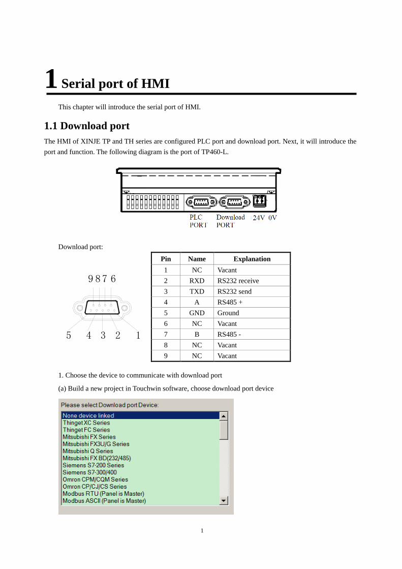
1.1 Download port
The HMI of XINJE TP and TH series are configured PLC port and download port. Next, it will introduce the
port and function. The following diagram is the port of TP460-L.
Download port:
12345
6789
Pin Name Explanation
1 NC Vacant
2 RXD RS232 receive
3 TXD RS232 send
4 A RS485 +
5 GND Ground
6 NC Vacant
7 B RS485 -
8 NC Vacant
9 NC Vacant
1. Choose the device to communicate with download port
(a) Build a new project in Touchwin software, choose download port device
2
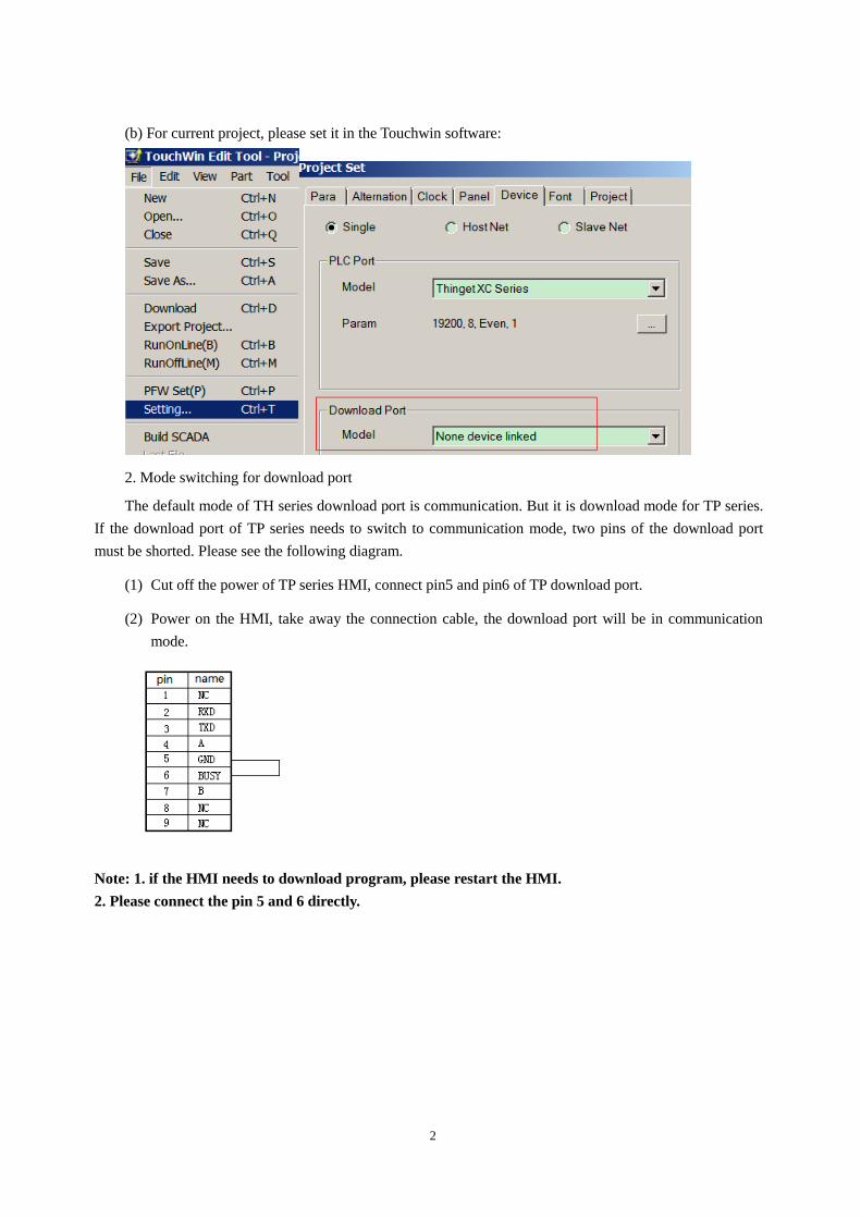
(b) For current project, please set it in the Touchwin software:
2. Mode switching for download port
The default mode of TH series download port is communication. But it is download mode for TP series.
If the download port of TP series needs to switch to communication mode, two pins of the download port
must be shorted. Please see the following diagram.
(1) Cut off the power of TP series HMI, connect pin5 and pin6 of TP download port.
(2) Power on the HMI, take away the connection cable, the download port will be in communication
mode.
Note: 1. if the HMI needs to download program, please restart the HMI.
2. Please connect the pin 5 and 6 directly.
3
1.2 PLC port
PLC port:
12345
6789
Pin Name Explanation
1 TD+ RS422 send -
2 RXD RS232 receive
3 TXD RS232 send
4 A RS485 +
5 GND Ground
6 TD- RS422 send -
7 B RS485 -
8 RDD- RS422 receive -
9 RDD+ RS422 receive +
For real application, pelase refer to chapter 2 for cable making. Refer to chapter 1.1 for download port
settings.
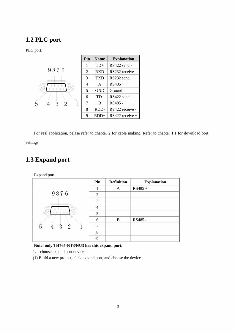
1.3 Expand port
Expand port:
12345
6789
Pin Definition Explanation
1 A RS485 +
2
3
4
5
6 B RS485 -
7
8
9
Note: only TH765-NT3/NU3 has this expand port.
1. choose expand port device
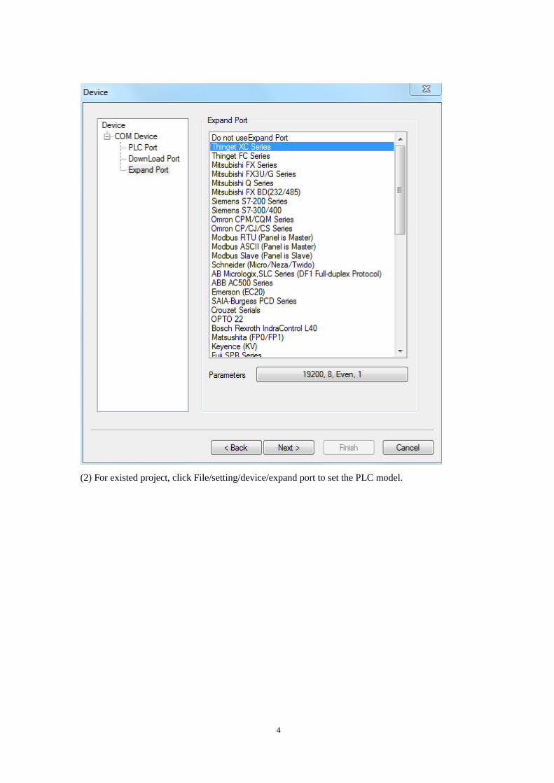
(1) Build a new project, click expand port, and choose the device
4
(2) For existed project, click File/setting/device/expand port to set the PLC model.
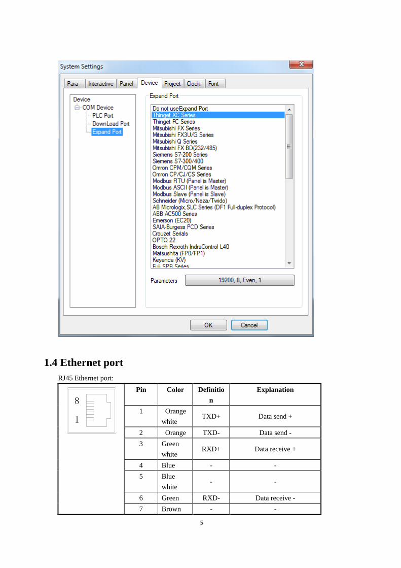
5
1.4 Ethernet port
RJ45 Ethernet port:
1
8
Pin Color Definitio
n
Explanation
1 Orange
white TXD+ Data send +
2 Orange TXD- Data send -
3 Green
white RXD+ Data receive +
4 Blue - -
5 Blue
white - -
6 Green RXD- Data receive -
7 Brown - -
6
white
8 Brown - -
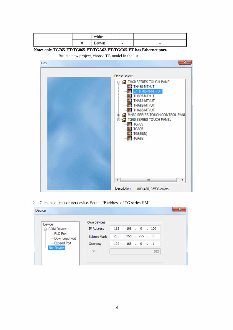
Note: only TG765-ET/TG865-ET/TGA62-ET/TGC65-ET has Ethernet port.
1. Build a new project, choose TG model in the list.
2. Click next, choose net device. Set the IP address of TG series HMI.
7
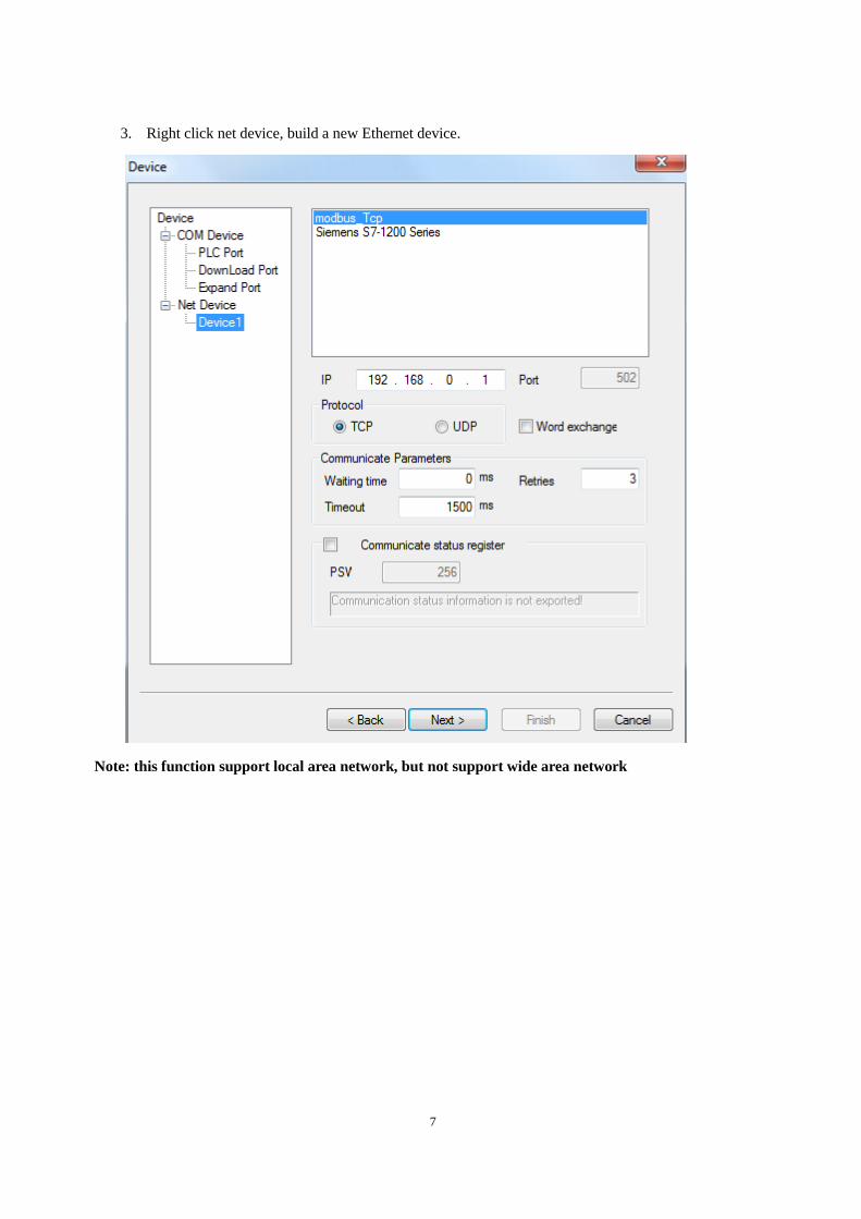
3. Right click net device, build a new Ethernet device.
Note: this function support local area network, but not support wide area network
8
2 The connection of PLC and HMI
This chapter will introduce the connection between PLC and HMI.
Please don’t pull out or plug the cable when power on, the serial port may be damaged.
2.1 XINJE FC series PLC
2.1.1Model
Series CPU Connected
module Port
Cable
making Device
FC XC32V2-CPU030427-
R5
CPU direct
connection
RS232 Fig1 Xinje FC series
RS485 Fig2
2.1.2 Parameters
HMI parameters:
Parameters Settings Choices for settings Item
PLC type FC series
Port RS232 RS232or RS485
Data bit 8 7 or 8
Stop bit 1 1 or 2
Parity Odd parity Odd/even/no parity
Baud rate 9600 4800/38400/9600/115200/19200/187500
Station No. 0 0~255
The default communication parameters of FC: 9600, 8, 1, odd parity, station No.0.
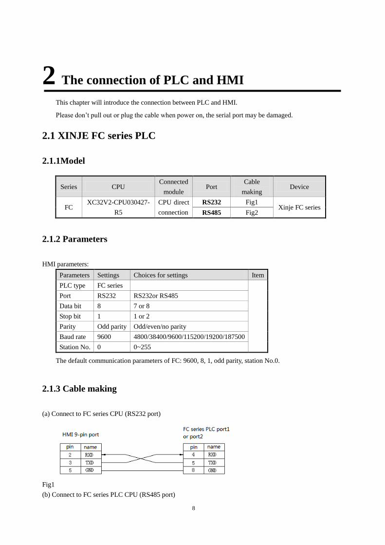
2.1.3 Cable making
(a) Connect to FC series CPU (RS232 port)
Fig1
(b) Connect to FC series PLC CPU (RS485 port)
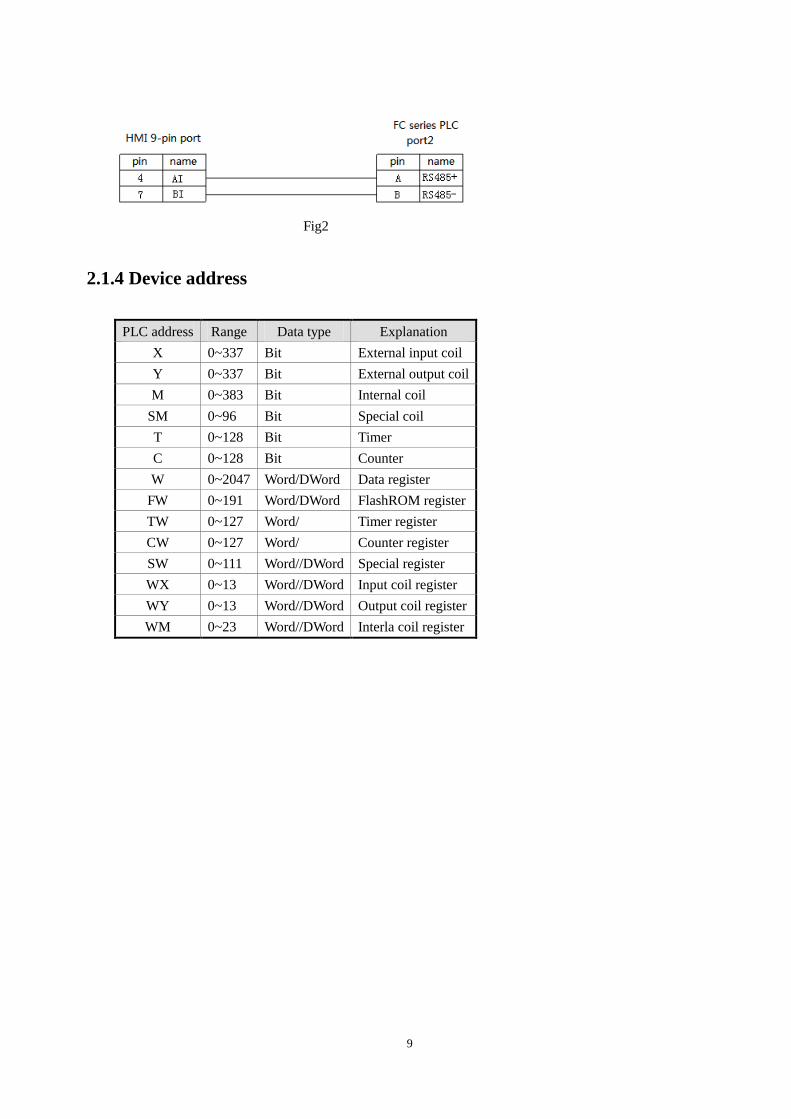
9
Fig2
2.1.4 Device address
PLC address Range Data type Explanation
X 0~337 Bit External input coil
Y 0~337 Bit External output coil
M 0~383 Bit Internal coil
SM 0~96 Bit Special coil
T 0~128 Bit Timer
C 0~128 Bit Counter
W 0~2047 Word/DWord Data register
FW 0~191 Word/DWord FlashROM register
TW 0~127 Word/ Timer register
CW 0~127 Word/ Counter register
SW 0~111 Word//DWord Special register
WX 0~13 Word//DWord Input coil register
WY 0~13 Word//DWord Output coil register
WM 0~23 Word//DWord Interla coil register
10
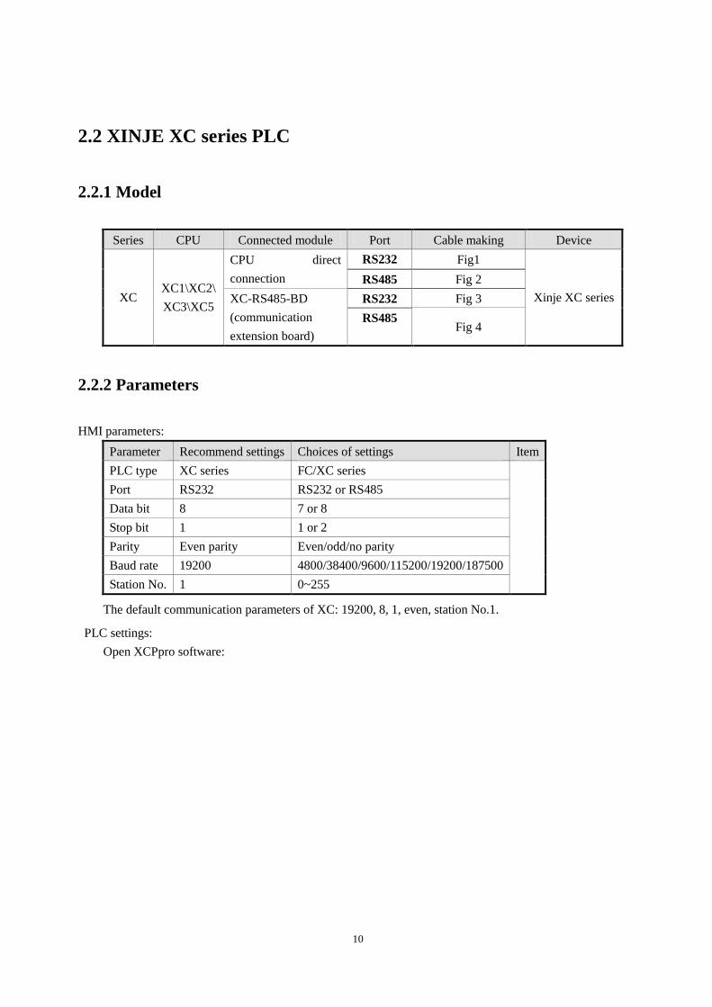
2.2 XINJE XC series PLC
2.2.1 Model
Series CPU Connected module Port Cable making Device
XC XC1\XC2\
XC3\XC5
CPU direct
connection
RS232 Fig1
Xinje XC series
RS485 Fig 2
XC-RS485-BD
(communication
extension board)
RS232 Fig 3
RS485 Fig 4
2.2.2 Parameters
HMI parameters:
Parameter Recommend settings Choices of settings Item
PLC type XC series FC/XC series
Port RS232 RS232 or RS485
Data bit 8 7 or 8
Stop bit 1 1 or 2
Parity Even parity Even/odd/no parity
Baud rate 19200 4800/38400/9600/115200/19200/187500
Station No. 1 0~255
The default communication parameters of XC: 19200, 8, 1, even, station No.1.
PLC settings:
Open XCPpro software:
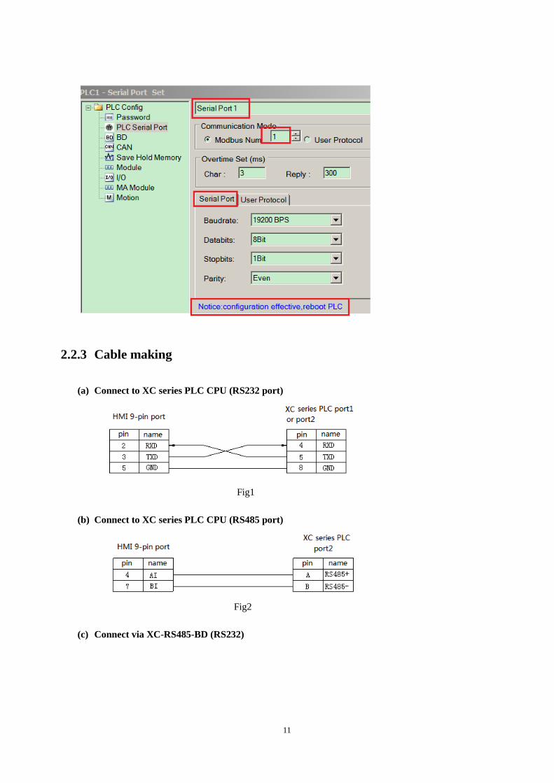
11
2.2.3 Cable making
(a) Connect to XC series PLC CPU (RS232 port)
Fig1
(b) Connect to XC series PLC CPU (RS485 port)
Fig2
(c) Connect via XC-RS485-BD (RS232)
12
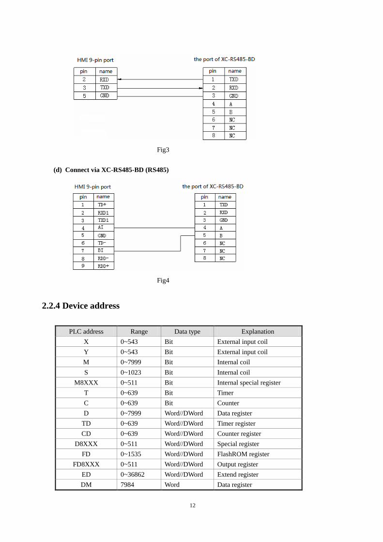
Fig3
(d) Connect via XC-RS485-BD (RS485)
Fig4
2.2.4 Device address
PLC address Range Data type Explanation
X 0~543 Bit External input coil
Y 0~543 Bit External input coil
M 0~7999 Bit Internal coil
S 0~1023 Bit Internal coil
M8XXX 0~511 Bit Internal special register
T 0~639 Bit Timer
C 0~639 Bit Counter
D 0~7999 Word//DWord Data register
TD 0~639 Word//DWord Timer register
CD 0~639 Word//DWord Counter register
D8XXX 0~511 Word//DWord Special register
FD 0~1535 Word//DWord FlashROM register
FD8XXX 0~511 Word//DWord Output register
ED 0~36862 Word//DWord Extend register
DM 7984 Word Data register

13
DX 0~52 Word Data register
DY 0~52 Word Data register
DS 0~1008 Word Data register
DM8XXX 0~496 Word Data register
DT 0~603 Word Data register
DC 0~619 Word Data register
ID 0~9999 Word//DWord Analog input
QD 0~9999 Word//DWord Analog output
14
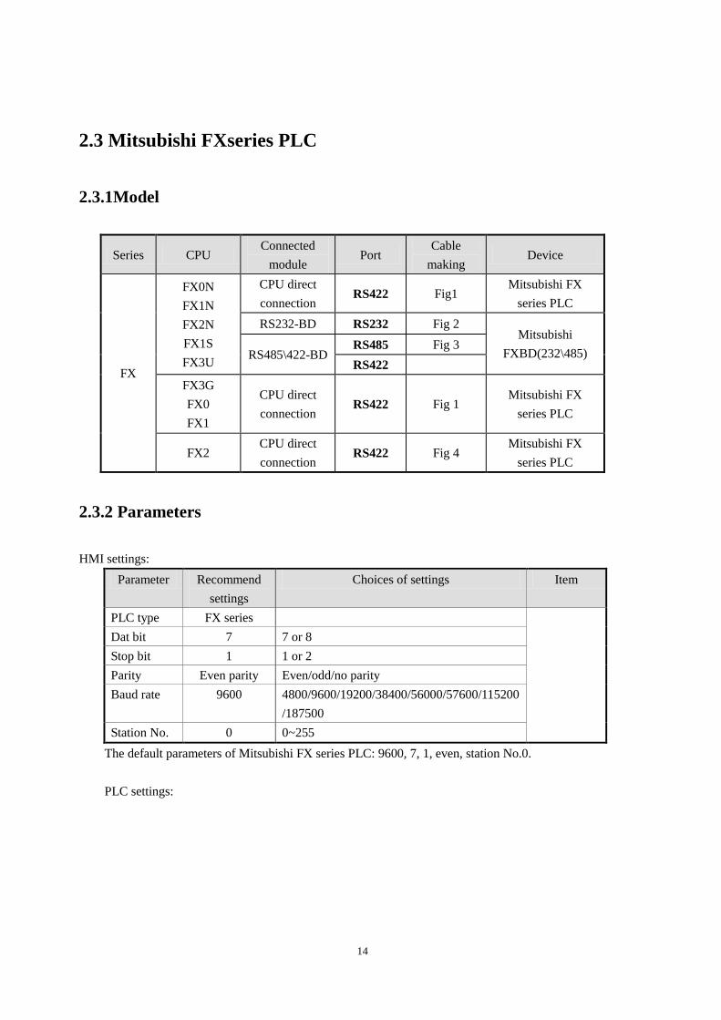
2.3 Mitsubishi FXseries PLC
2.3.1Model
Series CPU Connected
module Port
Cable
making Device
FX
FX0N
FX1N
FX2N
FX1S
FX3U
CPU direct
connection RS422 Fig1
Mitsubishi FX
series PLC
RS232-BD RS232 Fig 2 Mitsubishi
FXBD(232\485) RS485\422-BD RS485 Fig 3
RS422
FX3G
FX0
FX1
CPU direct
connection RS422 Fig 1
Mitsubishi FX
series PLC
FX2 CPU direct
connection RS422 Fig 4
Mitsubishi FX
series PLC
2.3.2 Parameters
HMI settings:
Parameter Recommend
settings
Choices of settings Item
PLC type FX series
Dat bit 7 7 or 8
Stop bit 1 1 or 2
Parity Even parity Even/odd/no parity
Baud rate 9600 4800/9600/19200/38400/56000/57600/115200
/187500
Station No. 0 0~255
The default parameters of Mitsubishi FX series PLC: 9600, 7, 1, even, station No.0.
PLC settings:
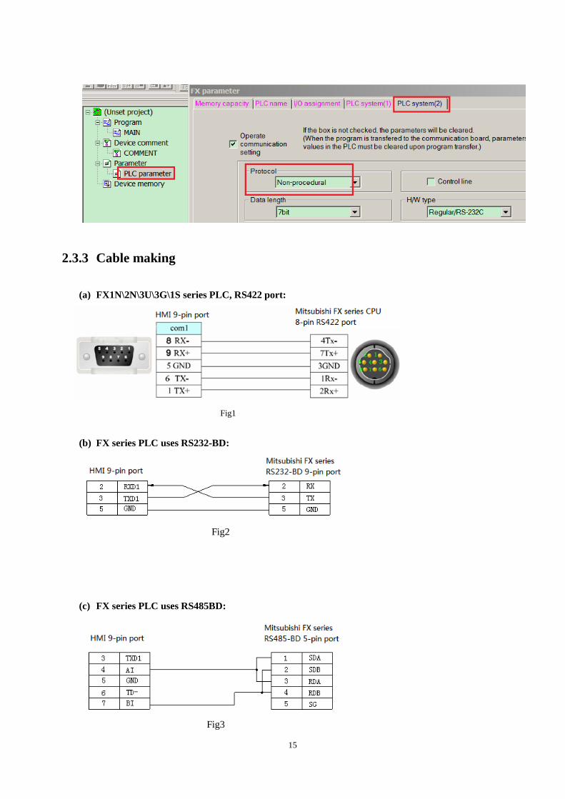
15
2.3.3 Cable making
(a) FX1N\2N\3U\3G\1S series PLC, RS422 port:
Fig1
(b) FX series PLC uses RS232-BD:
Fig2
(c) FX series PLC uses RS485BD:
Fig3
16
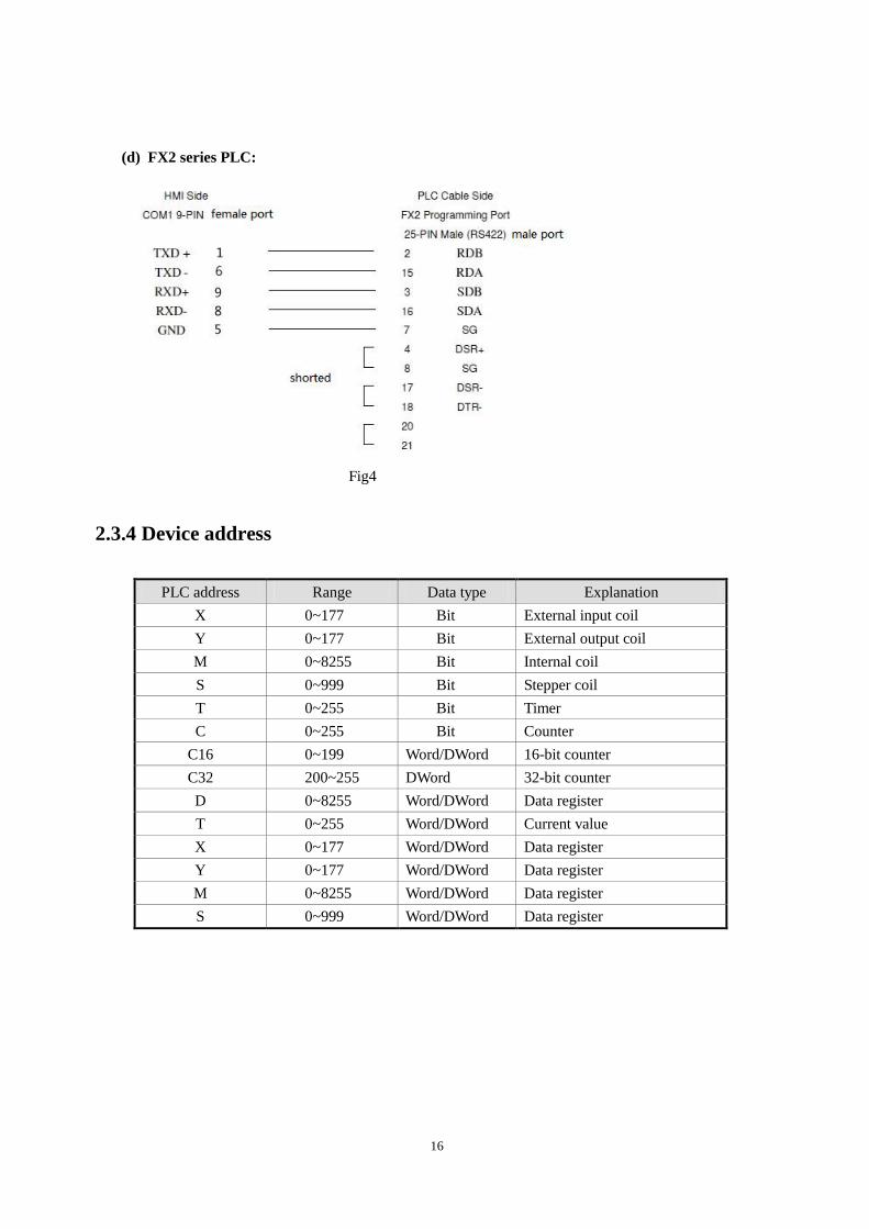
(d) FX2 series PLC:
Fig4
2.3.4 Device address
PLC address Range Data type Explanation
X 0~177 Bit External input coil
Y 0~177 Bit External output coil
M 0~8255 Bit Internal coil
S 0~999 Bit Stepper coil
T 0~255 Bit Timer
C 0~255 Bit Counter
C16 0~199 Word/DWord 16-bit counter
C32 200~255 DWord 32-bit counter
D 0~8255 Word/DWord Data register
T 0~255 Word/DWord Current value
X 0~177 Word/DWord Data register
Y 0~177 Word/DWord Data register
M 0~8255 Word/DWord Data register
S 0~999 Word/DWord Data register
17
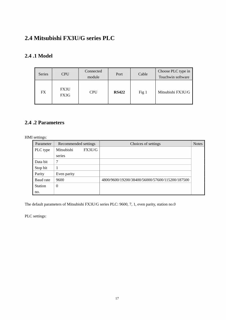
2.4 Mitsubishi FX3U/G series PLC
2.4 .1 Model
Series CPU Connected
module Port Cable
Choose PLC type in
Touchwin software
FX
FX3U
FX3G
CPU RS422 Fig 1 Mitsubishi FX3U/G
2.4 .2 Parameters
HMI settings:
Parameter Recommended settings Choices of settings Notes
PLC type Mitsubishi FX3U/G
series
Data bit 7
Stop bit 1
Parity Even parity
Baud rate 9600 4800/9600/19200/38400/56000/57600/115200/187500
Station
no.
0
The default parameters of Mitsubishi FX3U/G series PLC: 9600, 7, 1, even parity, station no.0
PLC settings:
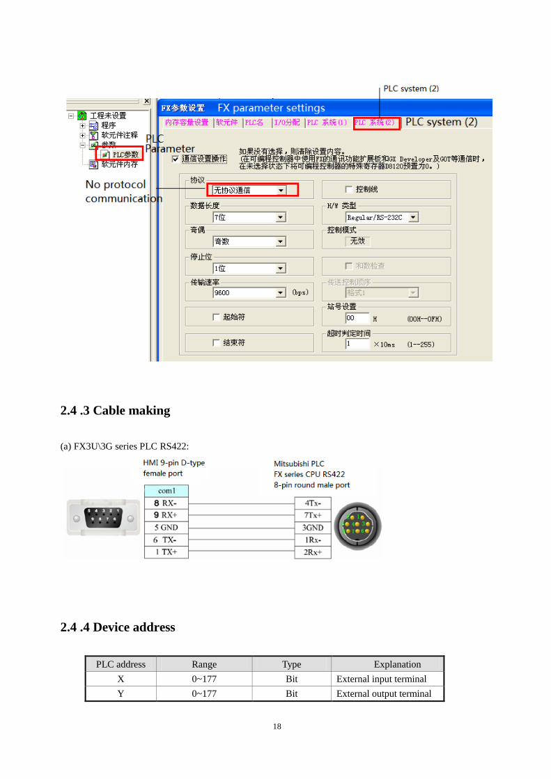
18
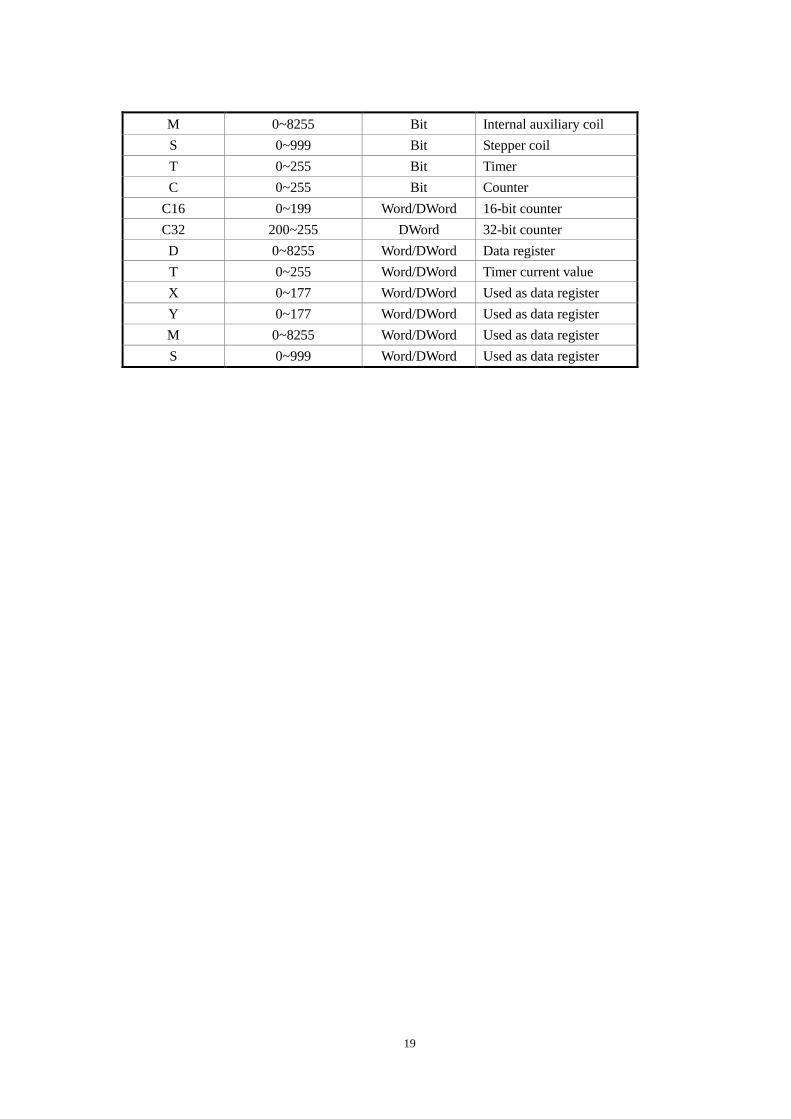
2.4 .3 Cable making
(a) FX3U\3G series PLC RS422:
2.4 .4 Device address
PLC address Range Type Explanation
X 0~177 Bit External input terminal
Y 0~177 Bit External output terminal
19
M 0~8255 Bit Internal auxiliary coil
S 0~999 Bit Stepper coil
T 0~255 Bit Timer
C 0~255 Bit Counter
C16 0~199 Word/DWord 16-bit counter
C32 200~255 DWord 32-bit counter
D 0~8255 Word/DWord Data register
T 0~255 Word/DWord Timer current value
X 0~177 Word/DWord Used as data register
Y 0~177 Word/DWord Used as data register
M 0~8255 Word/DWord Used as data register
S 0~999 Word/DWord Used as data register
20
2.5 Mitsubishi FX BD series PLC (RS232/485)
2.5.1 Device type
Series CPU Connected
module Port Cable
PLC type in Touchwin
software
FX
FX0N/1N/2N
FX1S
FX3U/3G
232-BD RS232 Fig1
Mitsubishi FX
BD(232\485)
485-BD RS485 Fig2
Note:
1. Do not hot plug the device!
2. The driver of 485-BD supports multi-station.
2.5.2 Parameters
HMI settings:
Parameters Recommend settings Choices of settings Notes
PLC type Mitsubishi FX BD(232\485)
Data bit 7
Stop bit 1
Parity Even parity
Baud rate 9600 9600/19200/38400/56000/57600/
115200/187500
Station no. 0 0~255
The default paramreters of Mitsubishi FX BD (232/485): 9600, 7, 1, even parity, station no.0
PLC settings:
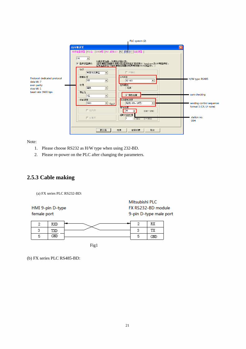
21
Note:
1. Please choose RS232 as H/W type when using 232-BD.
2. Please re-power on the PLC after changing the parameters.
2.5.3 Cable making
(a) FX series PLC RS232-BD:
Fig1
(b) FX series PLC RS485-BD:
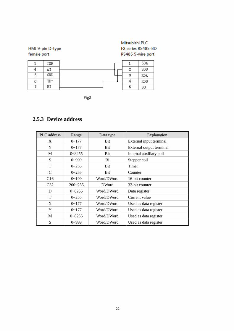
22
Fig2
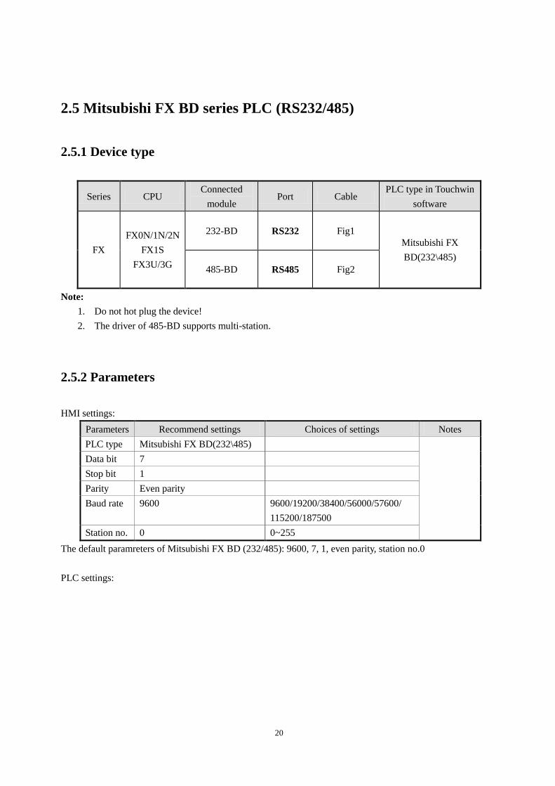
2.5.3 Device address
PLC address Range Data type Explanation
X 0~177 Bit External input terminal
Y 0~177 Bit External output terminal
M 0~8255 Bit Internal auxiliary coil
S 0~999 Bi Stepper coil
T 0~255 Bit Timer
C 0~255 Bit Counter
C16 0~199 Word/DWord 16-bit counter
C32 200~255 DWord 32-bit counter
D 0~8255 Word/DWord Data register
T 0~255 Word/DWord Current value
X 0~177 Word/DWord Used as data register
Y 0~177 Word/DWord Used as data register
M 0~8255 Word/DWord Used as data register
S 0~999 Word/DWord Used as data register

23
2.6 Mitsubishi Q series PLC
2.6 .1 Model
MELSEC-Q series include the CPU unit of Q00, Q01, Q00U and so on. They can connect to the HMI via
programmable port or communication module (QJ71C24N).
Series CPU Connected module Port Cable
making Device
Q
Q00
Q01
Q00U
CPU direct connection RS232 Fig 1 Mitsubishi Q
series
Q00J,Q00,
Q01,Q02H,
Q06H,Q12H,
Q25H,Q12PH,
Q25PH
Serial communication
module QJ71C24
RS232 Fig 2 Mitsubishi Q
series
RS422 Fig 3
2.6.2 Parameters
HMI settings:
Parameter Recommend setting Choices of settings Item
PLC type Q series
Data bit 8 7 or 8
Stop bit 1 1 or 2
Parity Odd parity Even/odd/no parity
Baud rate 19200 4800/9600/19200/38400/56000/57600/115200/187500
Station No. 0 0~255
The default parameter of Q series PLC: 19200, 8, 1, odd parity, station No.0.
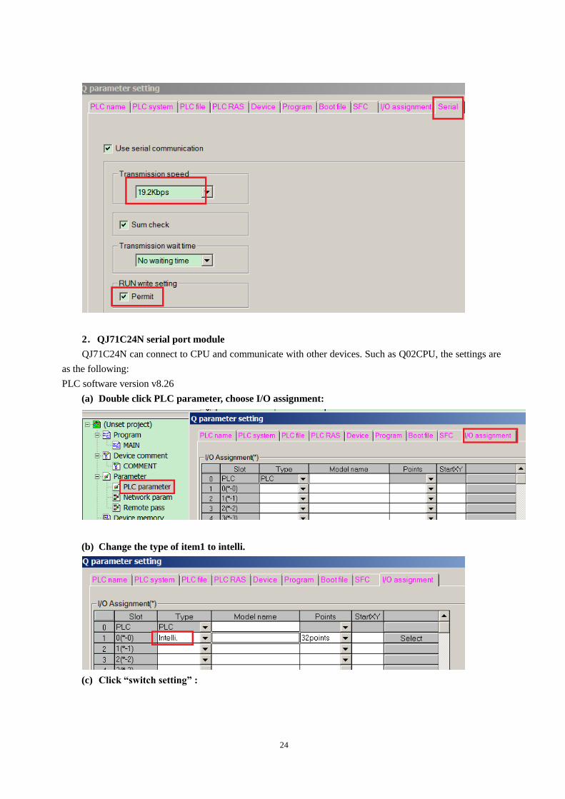
PLC settings:
1. Q01\Q00 PLC:
24
2.QJ71C24N serial port module
QJ71C24N can connect to CPU and communicate with other devices. Such as Q02CPU, the settings are
as the following:
PLC software version v8.26
(a) Double click PLC parameter, choose I/O assignment:
(b) Change the type of item1 to intelli.
(c) Click “switch setting” :
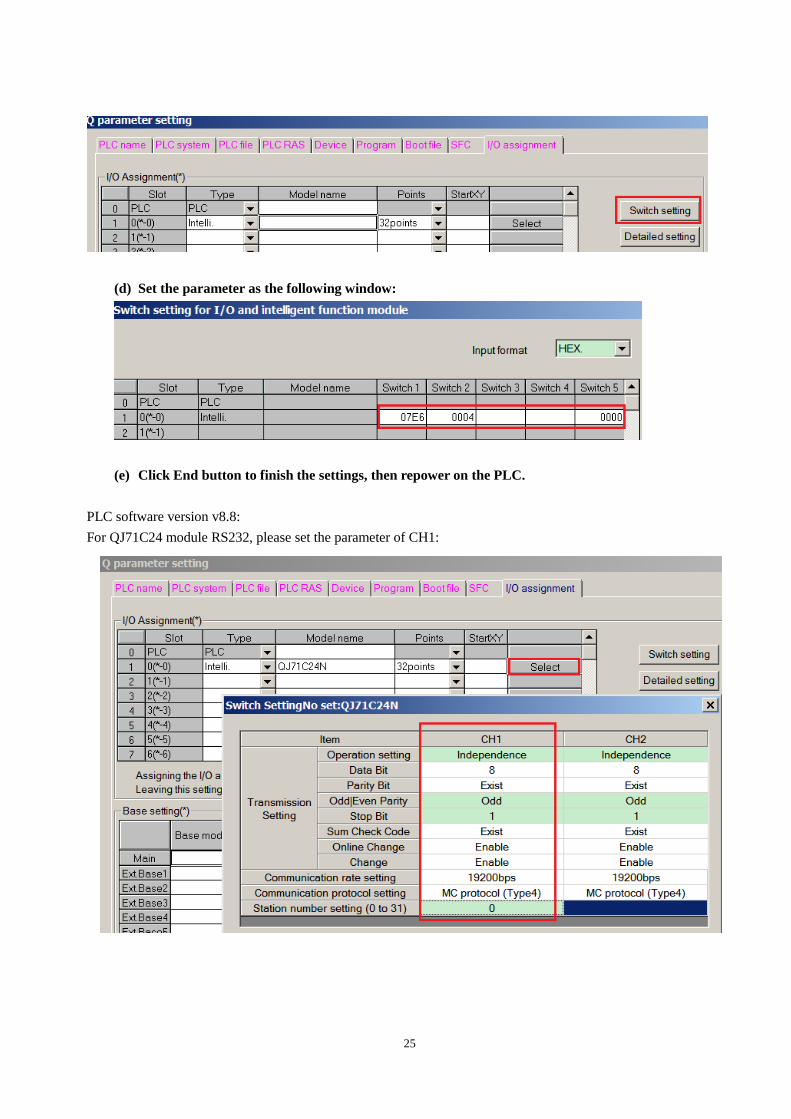
25
(d) Set the parameter as the following window:
(e) Click End button to finish the settings, then repower on the PLC.
PLC software version v8.8:
For QJ71C24 module RS232, please set the parameter of CH1:
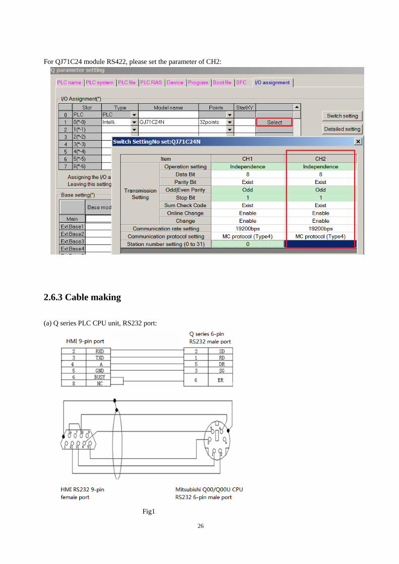
26
For QJ71C24 module RS422, please set the parameter of CH2:
2.6.3 Cable making
(a) Q series PLC CPU unit, RS232 port:
Fig1
27
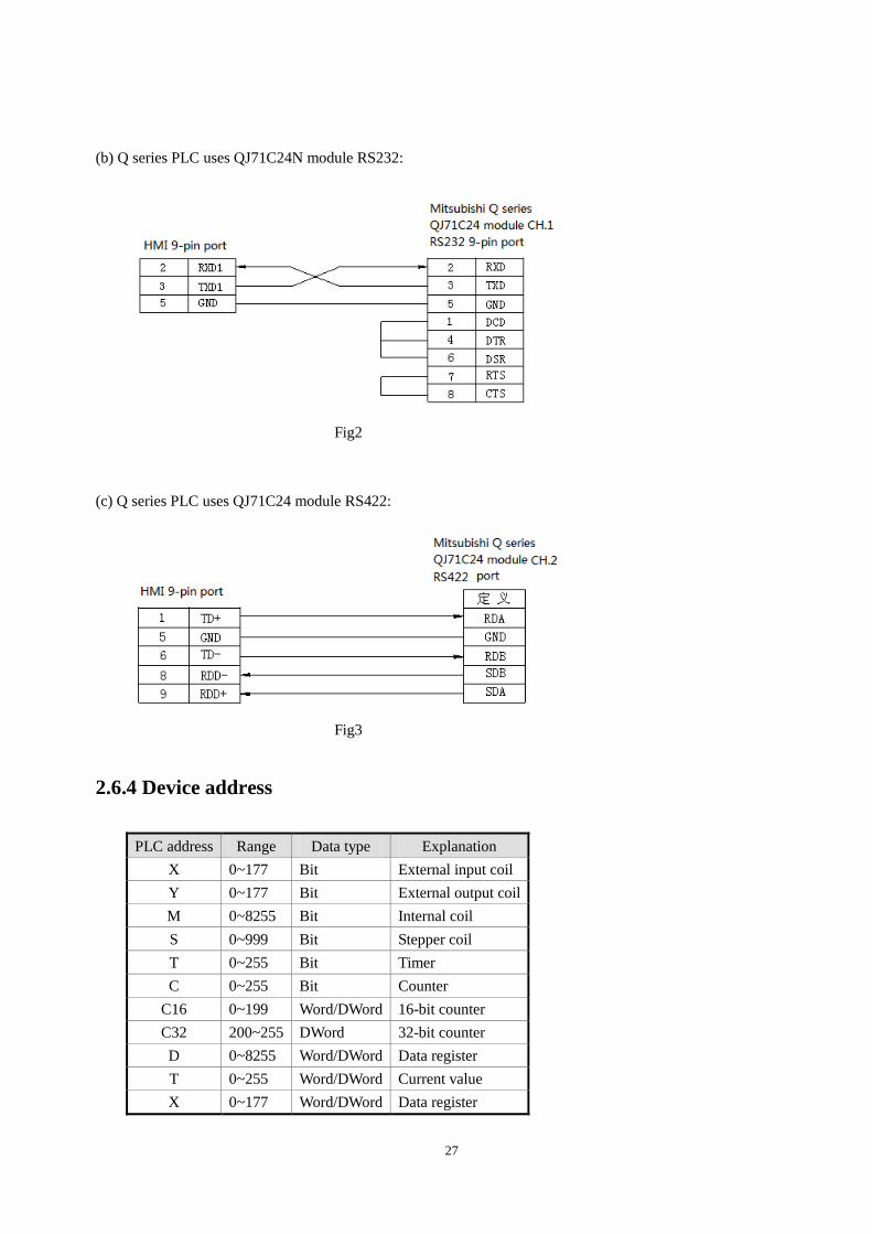
(b) Q series PLC uses QJ71C24N module RS232:
Fig2
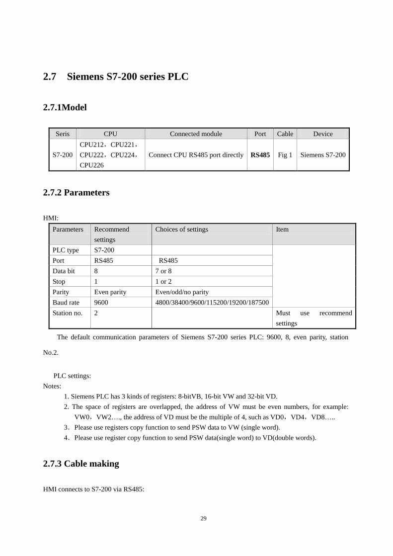
(c) Q series PLC uses QJ71C24 module RS422:
Fig3
2.6.4 Device address
PLC address Range Data type Explanation
X 0~177 Bit External input coil
Y 0~177 Bit External output coil
M 0~8255 Bit Internal coil
S 0~999 Bit Stepper coil
T 0~255 Bit Timer
C 0~255 Bit Counter
C16 0~199 Word/DWord 16-bit counter
C32 200~255 DWord 32-bit counter
D 0~8255 Word/DWord Data register
T 0~255 Word/DWord Current value
X 0~177 Word/DWord Data register

28
Y 0~177 Word/DWord Data register
M 0~8255 Word/DWord Data register
S 0~999 Word/DWord Data register
29
2.7 Siemens S7-200 series PLC
2.7.1Model
Seris CPU Connected module Port Cable Device
S7-200
CPU212,CPU221,
CPU222,CPU224,
CPU226
Connect CPU RS485 port directly RS485 Fig 1 Siemens S7-200
2.7.2 Parameters
HMI:
Parameters Recommend
settings
Choices of settings Item
PLC type S7-200
Port RS485 RS485
Data bit 8 7 or 8
Stop 1 1 or 2
Parity Even parity Even/odd/no parity
Baud rate 9600 4800/38400/9600/115200/19200/187500
Station no. 2 Must use recommend
settings
The default communication parameters of Siemens S7-200 series PLC: 9600, 8, even parity, station
No.2.
PLC settings:
Notes:
1. Siemens PLC has 3 kinds of registers: 8-bitVB, 16-bit VW and 32-bit VD.
2. The space of registers are overlapped, the address of VW must be even numbers, for example:
VW0,VW2…., the address of VD must be the multiple of 4, such as VD0,VD4,VD8…..
3.Please use registers copy function to send PSW data to VW (single word).
4.Please use register copy function to send PSW data(single word) to VD(double words).
2.7.3 Cable making
HMI connects to S7-200 via RS485:
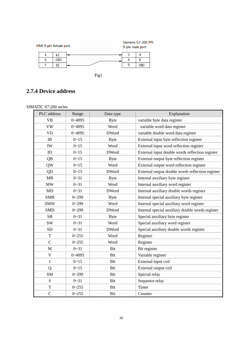
30
Fig1
2.7.4 Device address
SIMATIC S7-200 series
PLC address Range Data type Explanation
VB 0~4095 Byte variable byte data register
VW 0~4095 Word variable word data register
VD 0~4095 DWord variable double word data register
IB 0~15 Byte External input byte reflection register
IW 0~15 Word External input word reflection register
ID 0~15 DWord External input double words reflection register
QB 0~15 Byte External output byte reflection register
QW 0~15 Word External output word reflection register
QD 0~15 DWord External output double words reflection register
MB 0~31 Byte Internal auxiliary byte register
MW 0~31 Word Internal auxiliary word register
MD 0~31 DWord Internal auxiliary double words register
SMB 0~299 Byte Internal special auxiliary byte register
SMW 0~299 Word Internal special auxiliary word register
SMD 0~299 DWord Internal special auxiliary double words register
SB 0~31 Byte Special auxiliary byte register
SW 0~31 Word Special auxiliary word register
SD 0~31 DWord Special auxiliary double words register
T 0~255 Word Register
C 0~255 Word Register
M 0~31 Bit Bit register
V 0~4095 Bit Variable register
I 0~15 Bit External input coil
Q 0~15 Bit External output coil
SM 0~299 Bit Special relay
S 0~31 Bit Sequence relay
T 0~255 Bit Timer
C 0~255 Bit Counter
31
2.8 Siemens S7-300/400 series PLC
2.8.1 Model
SIMATIC S7-300/400 PLC (connect to CPU directly)
Series CPU Connected module Port Cable Device
S7-300 CPU312,CPU314,
CPU315 RS485 port of CPU
RS485 fig 1
Siemens SIMATIC
S7-300/400
PLC S7-400 CPU412-1,CPU412-2,
CPU414-2,
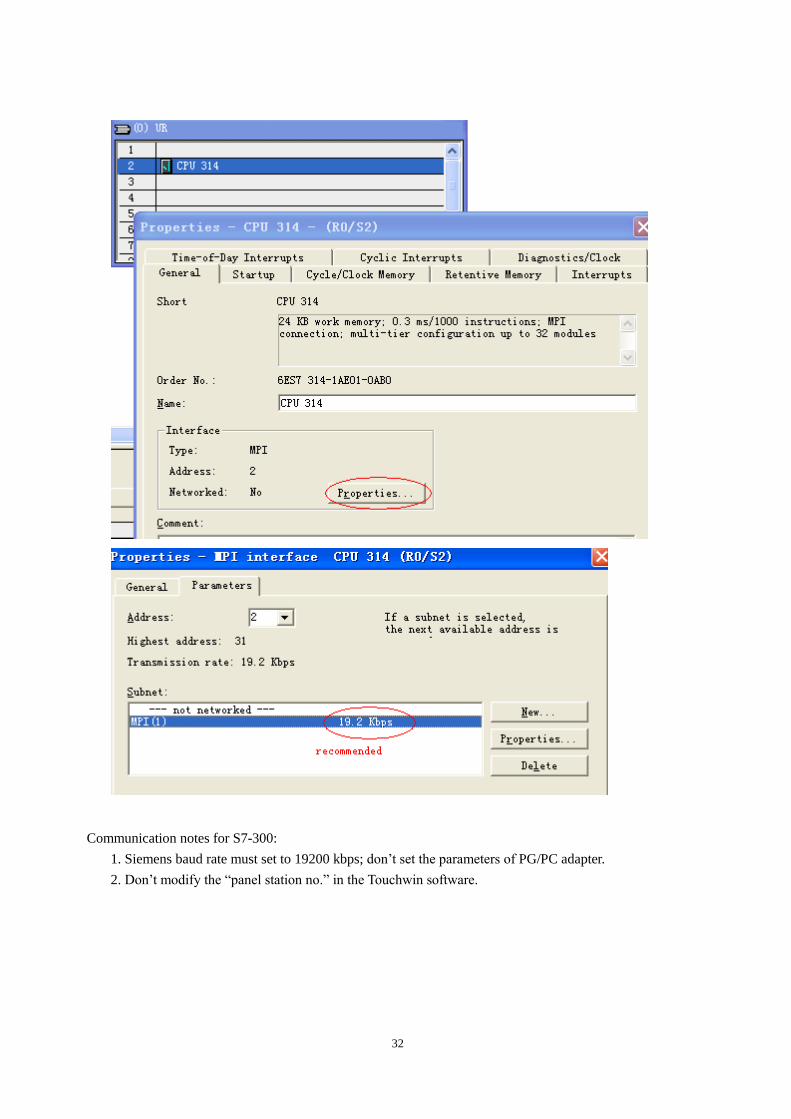
2.8.2 Parameters
HMI settings:
Parameter Recommend
settings
Choice of settings Note
PLC type S7-300/400
Port RS485
Data bit 8 7 or 8
Stop bit 1 1 or 2
Parity Even parity Even/odd/no parity
Baud rate 19200 4800/38400/9600/115200/19200/187500
Station
no.
2 Please use recommend
settings
The default parameters of Siemens S7-300\400: 19200, 8, even parity, station No.2.
PLC settings:
32
Communication notes for S7-300:
1. Siemens baud rate must set to 19200 kbps; don’t set the parameters of PG/PC adapter.
2. Don’t modify the “panel station no.” in the Touchwin software.
33
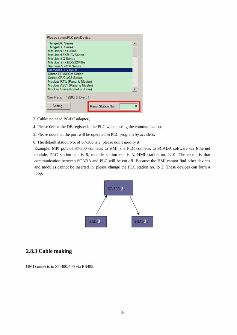
3. Cable: no need PG/PC adapter;
4. Please define the DB register in the PLC when testing the communication.
5. Please note that the port will be operated in PLC program by accident.
6. The default station No. of S7-300 is 2, please don’t modify it.
Example: MPI port of S7-300 connects to HMI, the PLC connects to SCADA software via Ethernet
module, PLC station no. is 8, module station no. is 3, HMI station no. is 0. The result is that
communication between SCADA and PLC will be cut off. Because the HMI cannot find other devices
and modules cannot be inserted in. please change the PLC station no. to 2. These devices can form a
loop:
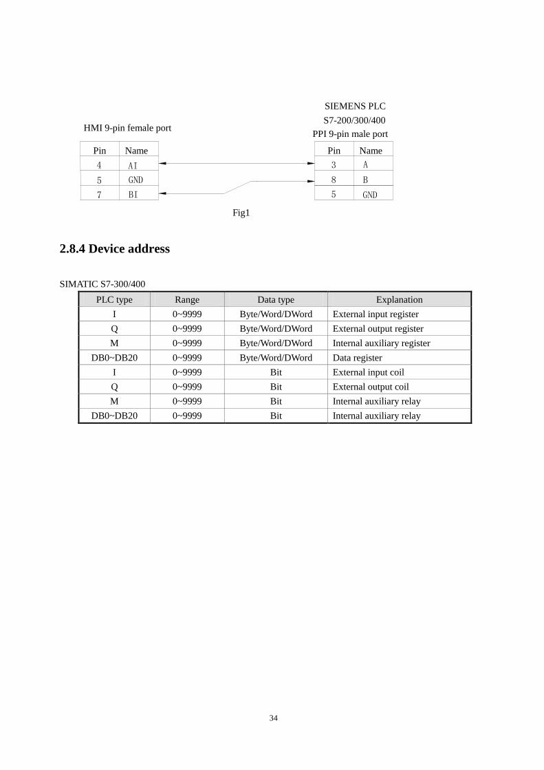
2.8.3 Cable making
HMI connects to S7-300/400 via RS485:
34
Fig1
2.8.4 Device address
SIMATIC S7-300/400
PLC type Range Data type Explanation
I 0~9999 Byte/Word/DWord External input register
Q 0~9999 Byte/Word/DWord External output register
M 0~9999 Byte/Word/DWord Internal auxiliary register
DB0~DB20 0~9999 Byte/Word/DWord Data register
I 0~9999 Bit External input coil
Q 0~9999 Bit External output coil
M 0~9999 Bit Internal auxiliary relay
DB0~DB20 0~9999 Bit Internal auxiliary relay
BI 7
S7-200/300/400
HMI 9-pin female port
GND
A
B
5
3
8
Name Pin Pin Name
5
4
GND
AI
SIEMENS PLC
PPI 9-pin male port
35
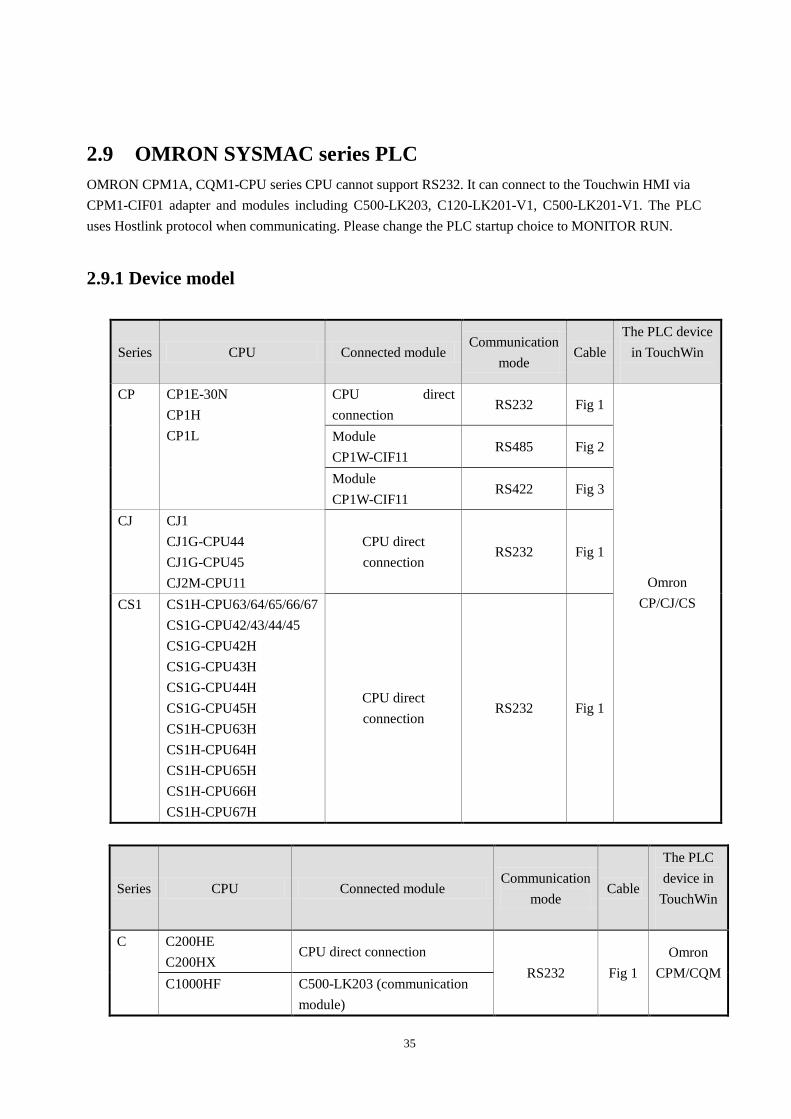
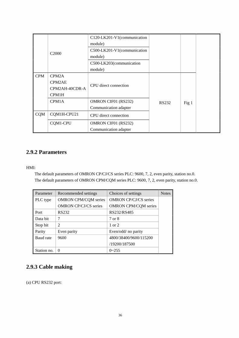
2.9 OMRON SYSMAC series PLC
OMRON CPM1A, CQM1-CPU series CPU cannot support RS232. It can connect to the Touchwin HMI via
CPM1-CIF01 adapter and modules including C500-LK203, C120-LK201-V1, C500-LK201-V1. The PLC
uses Hostlink protocol when communicating. Please change the PLC startup choice to MONITOR RUN.
2.9.1 Device model
Series CPU Connected module Communication
mode Cable
The PLC device
in TouchWin
CP CP1E-30N
CP1H
CP1L
CPU direct
connection RS232 Fig 1
Omron
CP/CJ/CS
Module
CP1W-CIF11 RS485 Fig 2
Module
CP1W-CIF11 RS422 Fig 3
CJ CJ1
CJ1G-CPU44
CJ1G-CPU45
CJ2M-CPU11
CPU direct
connection RS232 Fig 1
CS1 CS1H-CPU63/64/65/66/67
CS1G-CPU42/43/44/45
CS1G-CPU42H
CS1G-CPU43H
CS1G-CPU44H
CS1G-CPU45H
CS1H-CPU63H
CS1H-CPU64H
CS1H-CPU65H
CS1H-CPU66H
CS1H-CPU67H
CPU direct
connection RS232 Fig 1
Series CPU Connected module Communication
mode Cable
The PLC
device in
TouchWin
C C200HE
C200HX CPU direct connection
RS232 Fig 1
Omron
CPM/CQM
C1000HF C500-LK203 (communication
module)
36
C2000
C120-LK201-V1(communication
module)
C500-LK201-V1(communication
module)
C500-LK203(communication
module)
CPM CPM2A
CPM2AE
CPM2AH-40CDR-A
CPM1H
CPU direct connection
RS232 Fig 1 CPM1A OMRON CIF01 (RS232)
Communication adapter
CQM CQM1H-CPU21 CPU direct connection
CQM1-CPU OMRON CIF01 (RS232)
Communication adapter
2.9.2 Parameters
HMI:
The default parameters of OMRON CP/CJ/CS series PLC: 9600, 7, 2, even parity, station no.0.
The default parameters of OMRON CPM/CQM series PLC: 9600, 7, 2, even parity, station no.0.
Parameter Recommended settings Choices of settings Notes
PLC type OMRON CPM/CQM series
OMRON CP/CJ/CS series
OMRON CP/CJ/CS series
OMRON CPM/CQM series
Port RS232 RS232/RS485
Data bit 7 7 or 8
Stop bit 2 1 or 2
Parity Even parity Even/odd/ no parity
Baud rate 9600 4800/38400/9600/115200
/19200/187500
Station no. 0 0~255
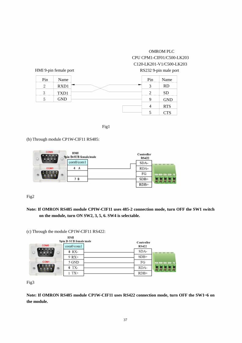
2.9.3 Cable making
(a) CPU RS232 port:
37
Fig1
(b) Through module CP1W-CIF11 RS485:
Fig2
Note: If OMRON RS485 module CPIW-CIF11 uses 485-2 connection mode, turn OFF the SW1 switch
on the module, turn ON SW2, 3, 5, 6. SW4 is selectable.
(c) Through the module CP1W-CIF11 RS422:
Fig3
Note: If OMRON RS485 module CP1W-CIF11 uses RS422 connection mode, turn OFF the SW1~6 on
the module.
OMROM PLC
TXD1
GND
RXD1
3
5
2
Name Pin Pin Name
2
3
9
SD
RD
GND
HMI 9-pin female port
CPU CPM1-CIF01/C500-LK203
RS232 9-pin male port
4 RTS
5 CTS
C120-LK201-V1/C500-LK203
38
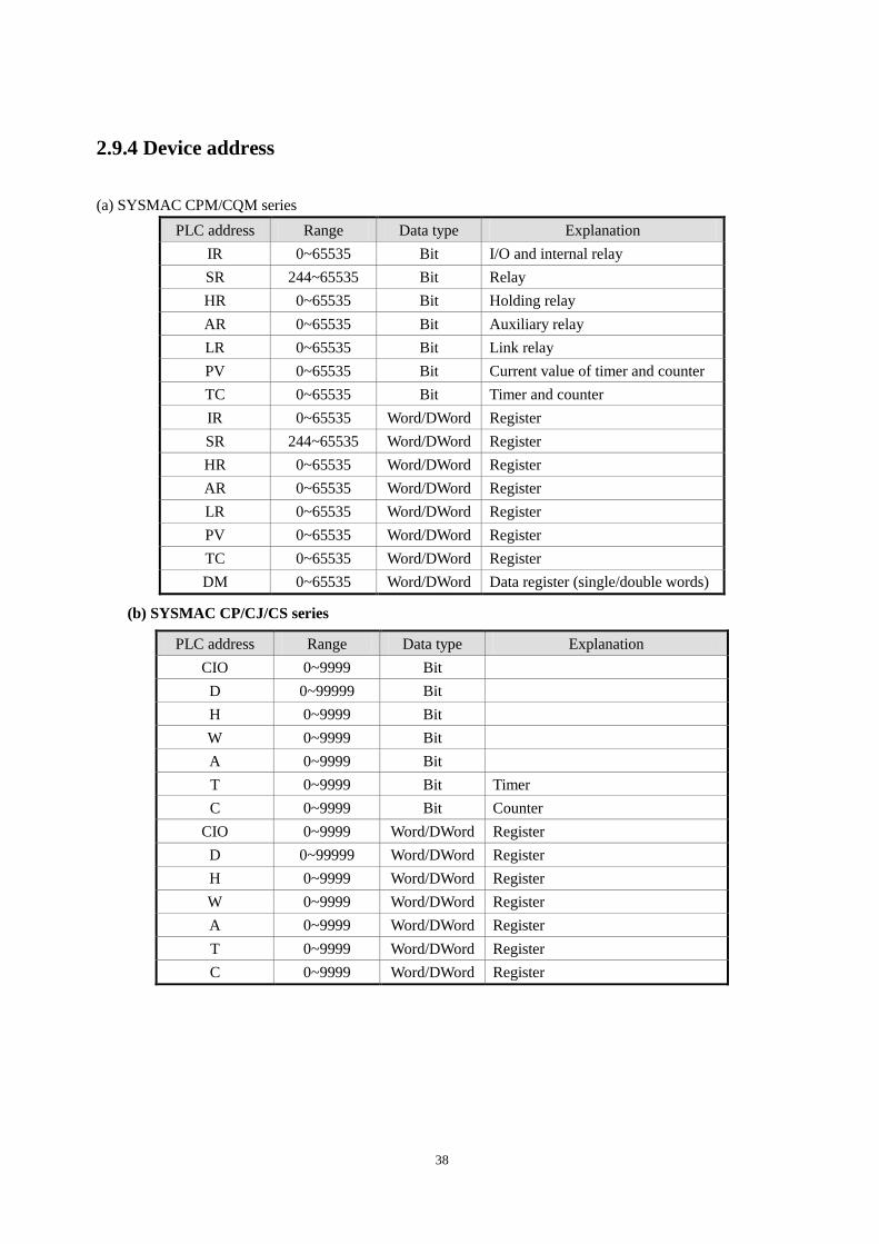
2.9.4 Device address
(a) SYSMAC CPM/CQM series
PLC address Range Data type Explanation
IR 0~65535 Bit I/O and internal relay
SR 244~65535 Bit Relay
HR 0~65535 Bit Holding relay
AR 0~65535 Bit Auxiliary relay
LR 0~65535 Bit Link relay
PV 0~65535 Bit Current value of timer and counter
TC 0~65535 Bit Timer and counter
IR 0~65535 Word/DWord Register
SR 244~65535 Word/DWord Register
HR 0~65535 Word/DWord Register
AR 0~65535 Word/DWord Register
LR 0~65535 Word/DWord Register
PV 0~65535 Word/DWord Register
TC 0~65535 Word/DWord Register
DM 0~65535 Word/DWord Data register (single/double words)
(b) SYSMAC CP/CJ/CS series
PLC address Range Data type Explanation
CIO 0~9999 Bit
D 0~99999 Bit
H 0~9999 Bit
W 0~9999 Bit
A 0~9999 Bit
T 0~9999 Bit Timer
C 0~9999 Bit Counter
CIO 0~9999 Word/DWord Register
D 0~99999 Word/DWord Register
H 0~9999 Word/DWord Register
W 0~9999 Word/DWord Register
A 0~9999 Word/DWord Register
T 0~9999 Word/DWord Register
C 0~9999 Word/DWord Register
39
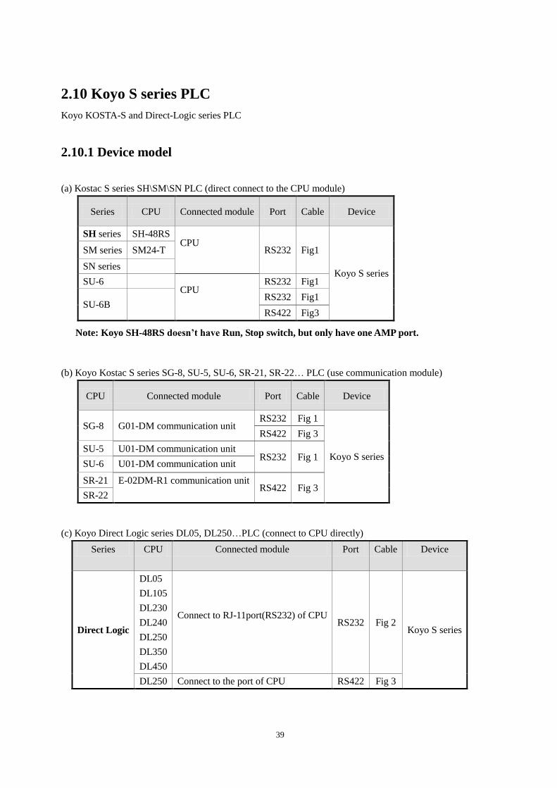
2.10 Koyo S series PLC
Koyo KOSTA-S and Direct-Logic series PLC
2.10.1 Device model
(a) Kostac S series SH\SM\SN PLC (direct connect to the CPU module)
Series CPU Connected module Port Cable Device
SH series SH-48RS CPU
RS232 Fig1
Koyo S series
SM series SM24-T
SN series
SU-6 CPU
RS232 Fig1
SU-6B RS232 Fig1
RS422 Fig3
Note: Koyo SH-48RS doesn’t have Run, Stop switch, but only have one AMP port.
(b) Koyo Kostac S series SG-8, SU-5, SU-6, SR-21, SR-22… PLC (use communication module)
CPU Connected module Port Cable Device
SG-8 G01-DM communication unit RS232 Fig 1
Koyo S series
RS422 Fig 3
SU-5 U01-DM communication unit RS232 Fig 1
SU-6 U01-DM communication unit
SR-21 E-02DM-R1 communication unit RS422 Fig 3
SR-22
(c) Koyo Direct Logic series DL05, DL250…PLC (connect to CPU directly)
Series CPU Connected module Port Cable Device
Direct Logic
DL05
DL105
DL230
DL240
DL250
DL350
DL450
Connect to RJ-11port(RS232) of CPU
RS232 Fig 2
Koyo S series
DL250 Connect to the port of CPU RS422 Fig 3
40
DL430
DL440
DL450
DL350
Connect to the port of CPU
RS232 Fig 2
Note: port2 of DL250CPU has RS232 and RS422; please indentify them when making the cable.
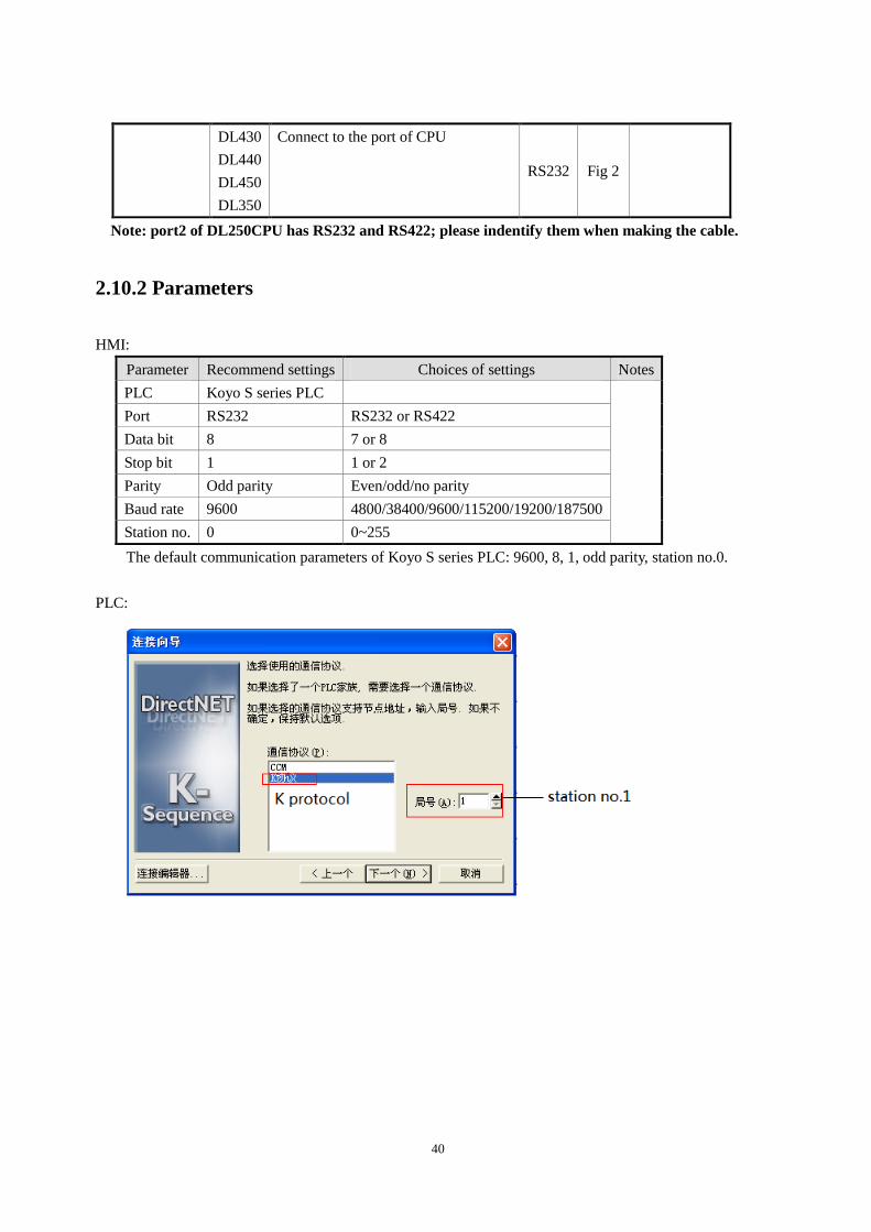
2.10.2 Parameters
HMI:
Parameter Recommend settings Choices of settings Notes
PLC Koyo S series PLC
Port RS232 RS232 or RS422
Data bit 8 7 or 8
Stop bit 1 1 or 2
Parity Odd parity Even/odd/no parity
Baud rate 9600 4800/38400/9600/115200/19200/187500
Station no. 0 0~255
The default communication parameters of Koyo S series PLC: 9600, 8, 1, odd parity, station no.0.
PLC:
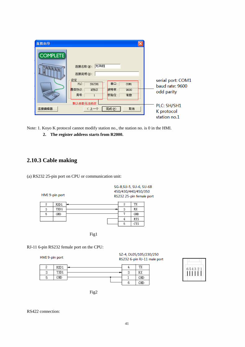
41
Note: 1. Koyo K protocol cannot modify station no., the station no. is 0 in the HMI.
2. The register address starts from R2000.
2.10.3 Cable making
(a) RS232 25-pin port on CPU or communication unit:
Fig1
RJ-11 6-pin RS232 female port on the CPU:
Fig2
RS422 connection:
123456
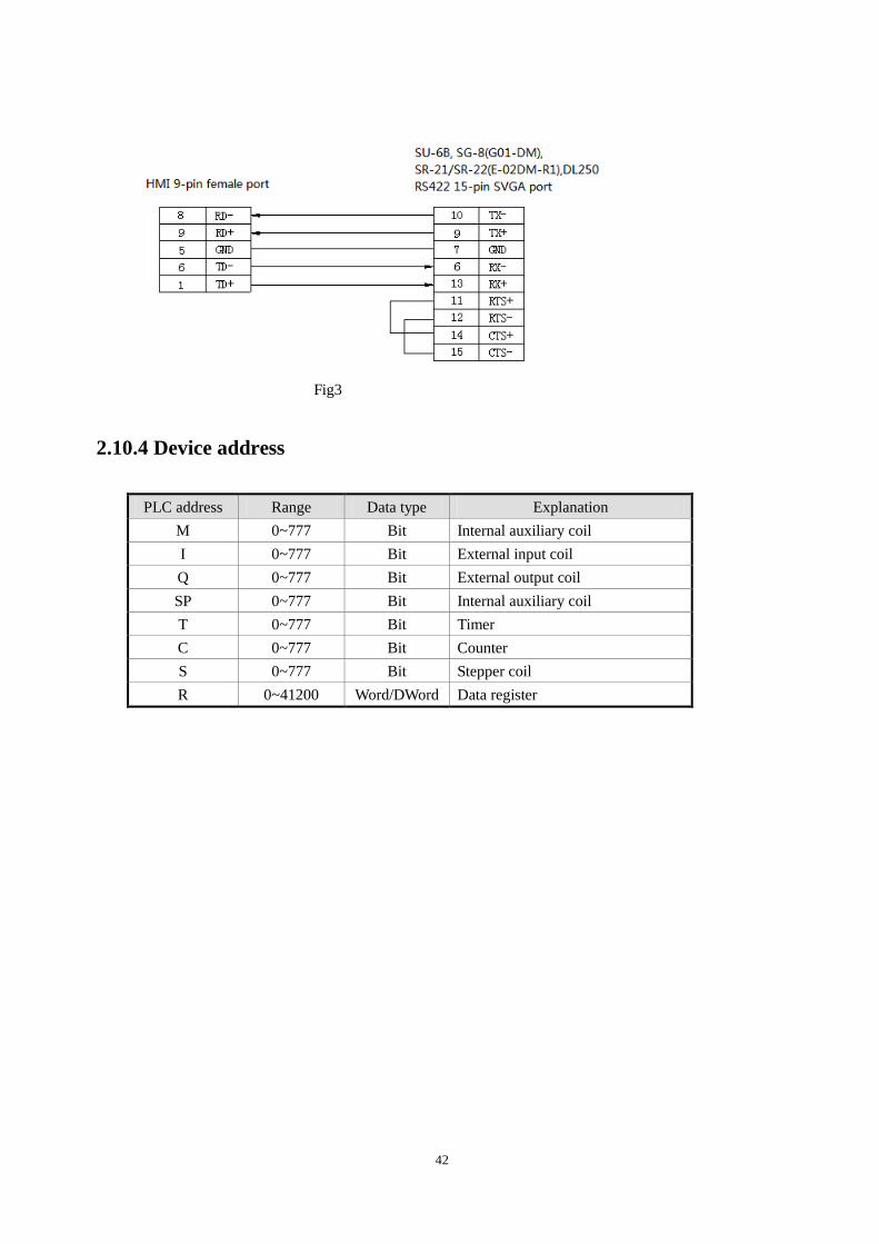
42
Fig3
2.10.4 Device address
PLC address Range Data type Explanation
M 0~777 Bit Internal auxiliary coil
I 0~777 Bit External input coil
Q 0~777 Bit External output coil
SP 0~777 Bit Internal auxiliary coil
T 0~777 Bit Timer
C 0~777 Bit Counter
S 0~777 Bit Stepper coil
R 0~41200 Word/DWord Data register
43
2.11 Koyo DL series PLC
2.11.1 Device type
Koyo Direct Logic series DL05, DL250 PLC (direct connect to CPU)
Series CPU Connected
module
Port Cable Choose PLC type in
Touchwin software
Direct
Logic
DL05
DL105
DL230
DL240
DL250
DL350
DL430
DL440
DL450
Connect to CPU
RJ-11 port RS232 Fig 1
Koyo DL series
Connect to CPU
com port RS422 Fig 2
Note: the port2 of DL250 has RS232 and RS422, please indentify the cable connection for them.
2.11.2 Parameters
HMI settings:
Parameters Recommend
settings
Choices of settings Note
PLC type Koyo DL series
Port RS232 RS232/RS422
Data bit 8 7/8
Stop bit 1 1/2
Parity Odd parity Even /odd /no parity
Baud rate 9600 4800/38400/9600/115200/19200/187500
Station no. 0 0-255
2.11.3 Cable making
RS232 Connection:
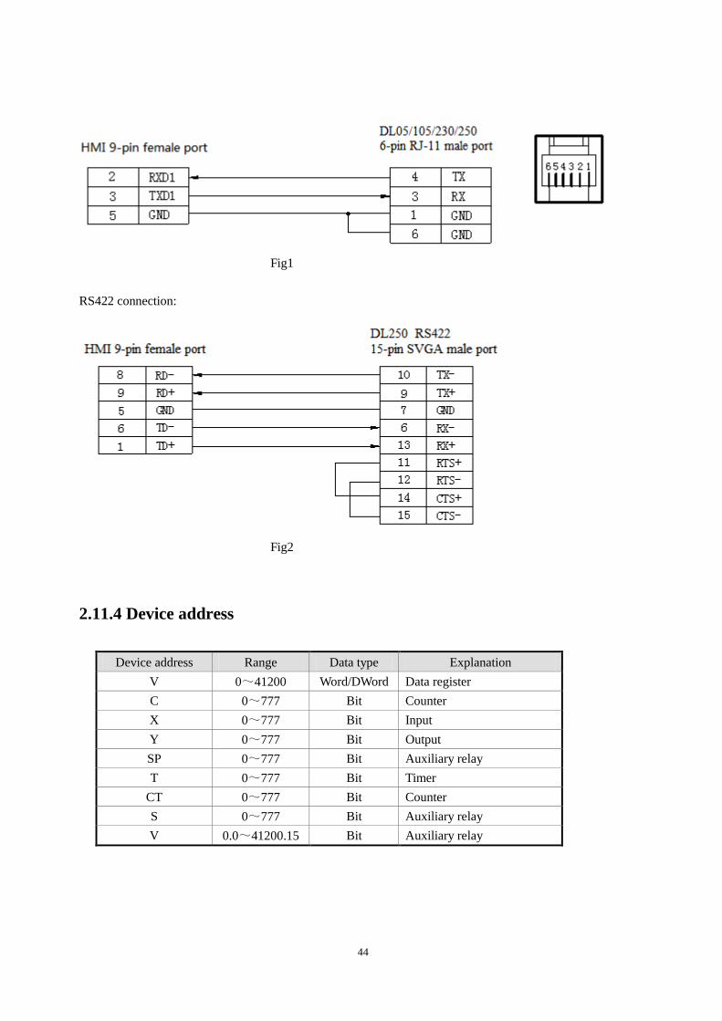
44
Fig1
RS422 connection:
Fig2
2.11.4 Device address
Device address Range Data type Explanation
V 0~41200 Word/DWord Data register
C 0~777 Bit Counter
X 0~777 Bit Input
Y 0~777 Bit Output
SP 0~777 Bit Auxiliary relay
T 0~777 Bit Timer
CT 0~777 Bit Counter
S 0~777 Bit Auxiliary relay
V 0.0~41200.15 Bit Auxiliary relay
45
2.12 Delta DVP series PLC
2.12.1Model
Delta DVP series CPU Connected module Port Cable Deivce
ES\EH\EX
Direct connect to the CPU
RS232 Fig 1
Delta DVP series RS485 Fig 2
SS\SA\SC\SX RS232 Fig 1
RS485 Fig 2
2.12.2 Parameters
HMI:
Parameters Recommend settings Choices of settings Notes
PLC type Delta DVP series
Port RS232 RS232 or RS485
Data bit 7 7 or 8
Stop bit 1 1 or 2
Parity Even parity Even/odd/no parity
Baud rate 9600 4800/38400/9600/115200/19200/187500
Station no. 1 0~255
The default communication parameters of Delta DVP series PLC: 9600, 7, 1, even parity, station no.1.
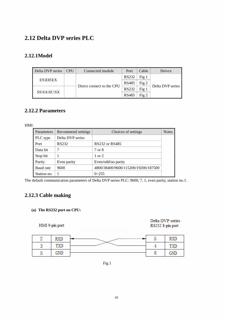
2.12.3 Cable making
(a) The RS232 port on CPU:
Fig 1
46
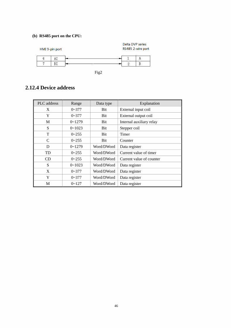
(b) RS485 port on the CPU:
Fig2
2.12.4 Device address
PLC address Range Data type Explanation
X 0~377 Bit External input coil
Y 0~377 Bit External output coil
M 0~1279 Bit Internal auxiliary relay
S 0~1023 Bit Stepper coil
T 0~255 Bit Timer
C 0~255 Bit Counter
D 0~1279 Word/DWord Data register
TD 0~255 Word/DWord Current value of timer
CD 0~255 Word/DWord Current value of counter
S 0~1023 Word/DWord Data register
X 0~377 Word/DWord Data register
Y 0~377 Word/DWord Data register
M 0~127 Word/DWord Data register
47
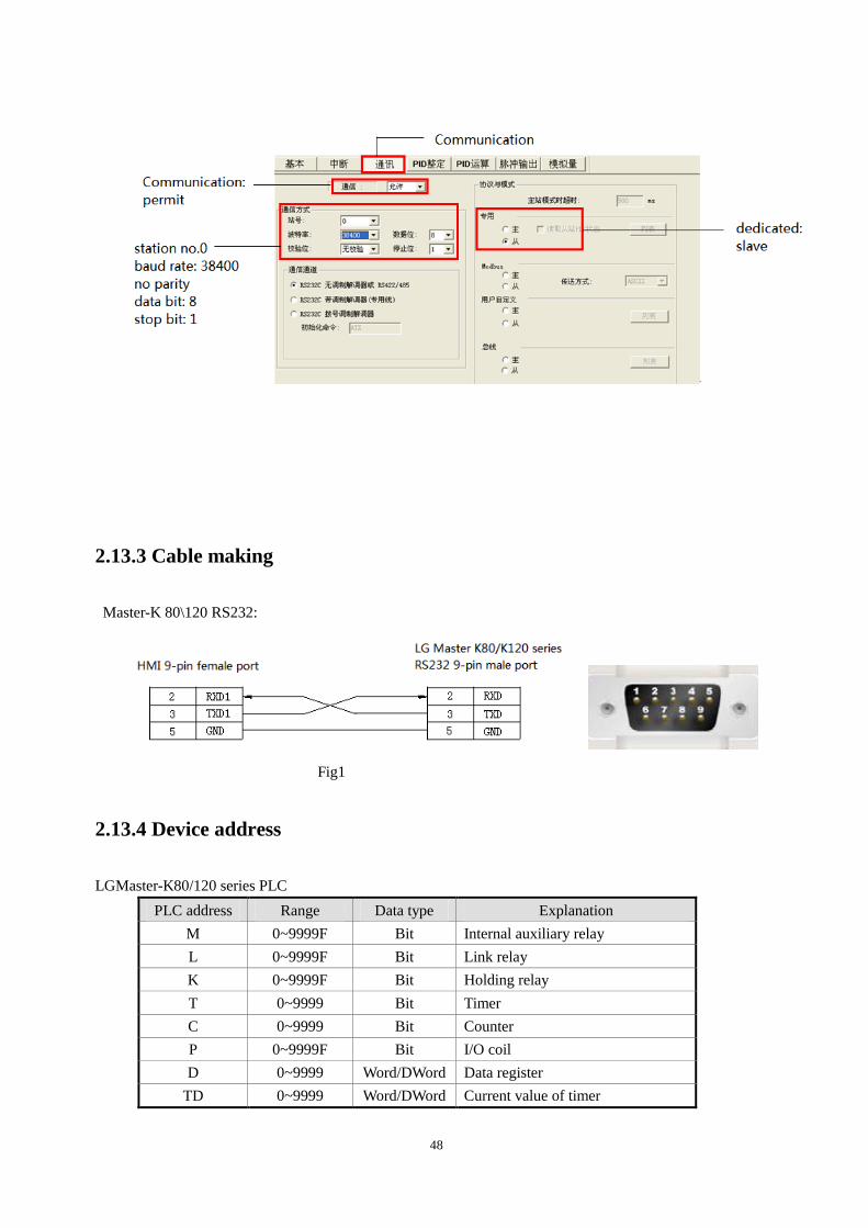
2.13 LG Master-K(CPU Direct) series PLC
LG Master-K series PLC support CPU(RS232) and Cnet module communication mode. This chapter
will introduce CPU mode.
2.13.1 Device model
Series Connected module Port Cable Device
K80
K120 CPU RS232 Fig 1 LG Master-K80/120 series
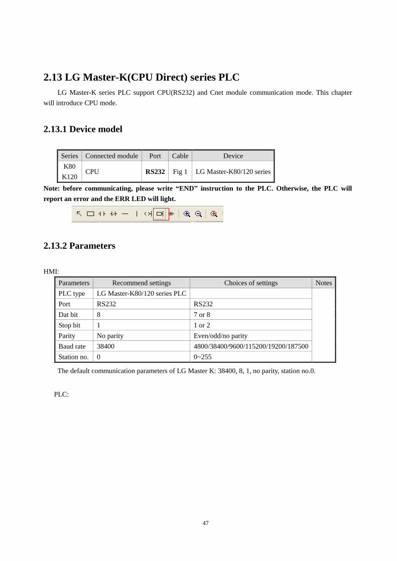
Note: before communicating, please write “END” instruction to the PLC. Otherwise, the PLC will
report an error and the ERR LED will light.
2.13.2 Parameters
HMI:
Parameters Recommend settings Choices of settings Notes
PLC type LG Master-K80/120 series PLC
Port RS232 RS232
Dat bit 8 7 or 8
Stop bit 1 1 or 2
Parity No parity Even/odd/no parity
Baud rate 38400 4800/38400/9600/115200/19200/187500
Station no. 0 0~255
The default communication parameters of LG Master K: 38400, 8, 1, no parity, station no.0.
PLC:
48
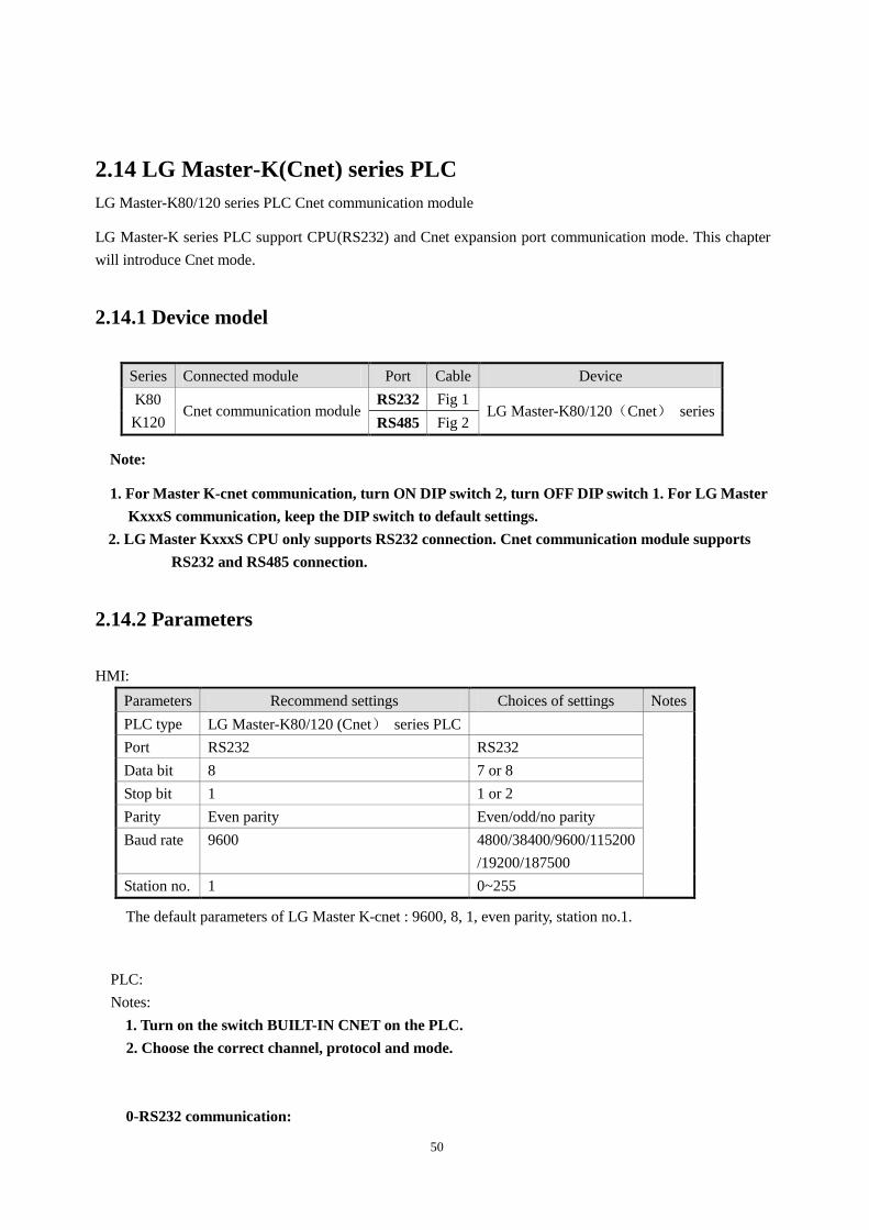
2.13.3 Cable making
Master-K 80\120 RS232:
Fig1
2.13.4 Device address
LGMaster-K80/120 series PLC
PLC address Range Data type Explanation
M 0~9999F Bit Internal auxiliary relay
L 0~9999F Bit Link relay
K 0~9999F Bit Holding relay
T 0~9999 Bit Timer
C 0~9999 Bit Counter
P 0~9999F Bit I/O coil
D 0~9999 Word/DWord Data register
TD 0~9999 Word/DWord Current value of timer

49
CD 0~9999 Word/DWord Current value of counter
S 0~9999 Word/DWord Used as register
K 0~9999 Word/DWord Used as register
M 0~9999 Word/DWord Used as register
L 0~9999 Word/DWord Used as register
F 0~9999 Word/DWord Used as register
P 0~9999 Word/DWord Used as register
50
2.14 LG Master-K(Cnet) series PLC
LG Master-K80/120 series PLC Cnet communication module
LG Master-K series PLC support CPU(RS232) and Cnet expansion port communication mode. This chapter
will introduce Cnet mode.
2.14.1 Device model
Series Connected module Port Cable Device
K80
K120 Cnet communication module
RS232 Fig 1 LG Master-K80/120(Cnet) series
RS485 Fig 2
Note:
1. For Master K-cnet communication, turn ON DIP switch 2, turn OFF DIP switch 1. For LG Master
KxxxS communication, keep the DIP switch to default settings.
2. LG Master KxxxS CPU only supports RS232 connection. Cnet communication module supports
RS232 and RS485 connection.
2.14.2 Parameters
HMI:
Parameters Recommend settings Choices of settings Notes
PLC type LG Master-K80/120 (Cnet) series PLC
Port RS232 RS232
Data bit 8 7 or 8
Stop bit 1 1 or 2
Parity Even parity Even/odd/no parity
Baud rate 9600 4800/38400/9600/115200
/19200/187500
Station no. 1 0~255
The default parameters of LG Master K-cnet : 9600, 8, 1, even parity, station no.1.
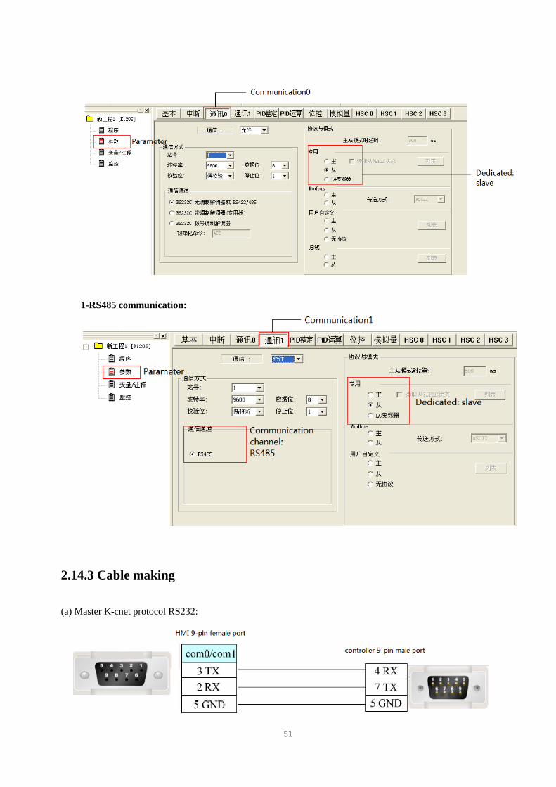
PLC:
Notes:
1. Turn on the switch BUILT-IN CNET on the PLC.
2. Choose the correct channel, protocol and mode.
0-RS232 communication:
51
1-RS485 communication:
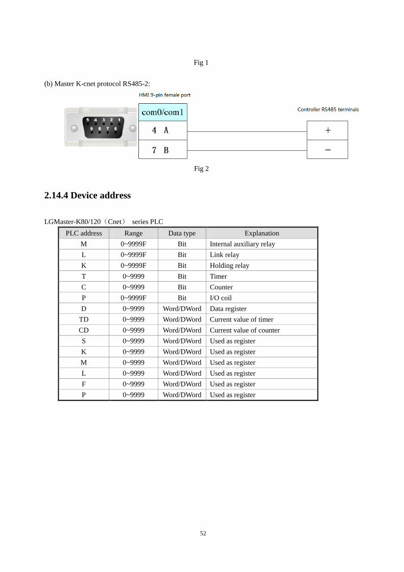
2.14.3 Cable making
(a) Master K-cnet protocol RS232:
52
Fig 1
(b) Master K-cnet protocol RS485-2:
Fig 2
2.14.4 Device address
LGMaster-K80/120(Cnet) series PLC
PLC address Range Data type Explanation
M 0~9999F Bit Internal auxiliary relay
L 0~9999F Bit Link relay
K 0~9999F Bit Holding relay
T 0~9999 Bit Timer
C 0~9999 Bit Counter
P 0~9999F Bit I/O coil
D 0~9999 Word/DWord Data register
TD 0~9999 Word/DWord Current value of timer
CD 0~9999 Word/DWord Current value of counter
S 0~9999 Word/DWord Used as register
K 0~9999 Word/DWord Used as register
M 0~9999 Word/DWord Used as register
L 0~9999 Word/DWord Used as register
F 0~9999 Word/DWord Used as register
P 0~9999 Word/DWord Used as register
53
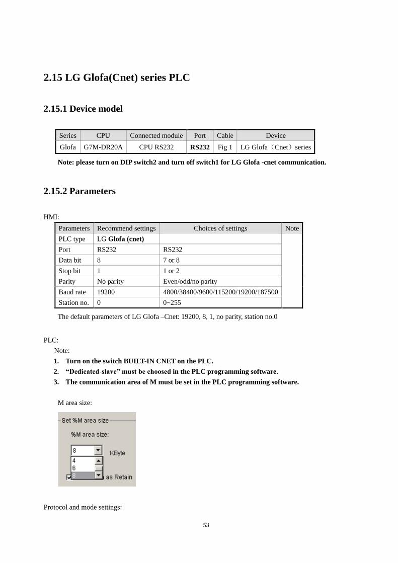
2.15 LG Glofa(Cnet) series PLC
2.15.1 Device model
Series CPU Connected module Port Cable Device
Glofa G7M-DR20A CPU RS232 RS232 Fig 1 LG Glofa(Cnet)series
Note: please turn on DIP switch2 and turn off switch1 for LG Glofa -cnet communication.
2.15.2 Parameters
HMI:
Parameters Recommend settings Choices of settings Note
PLC type LG Glofa (cnet)
Port RS232 RS232
Data bit 8 7 or 8
Stop bit 1 1 or 2
Parity No parity Even/odd/no parity
Baud rate 19200 4800/38400/9600/115200/19200/187500
Station no. 0 0~255
The default parameters of LG Glofa –Cnet: 19200, 8, 1, no parity, station no.0
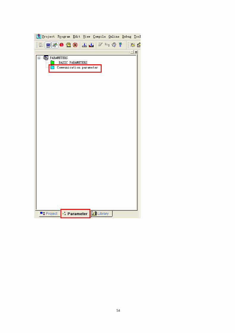
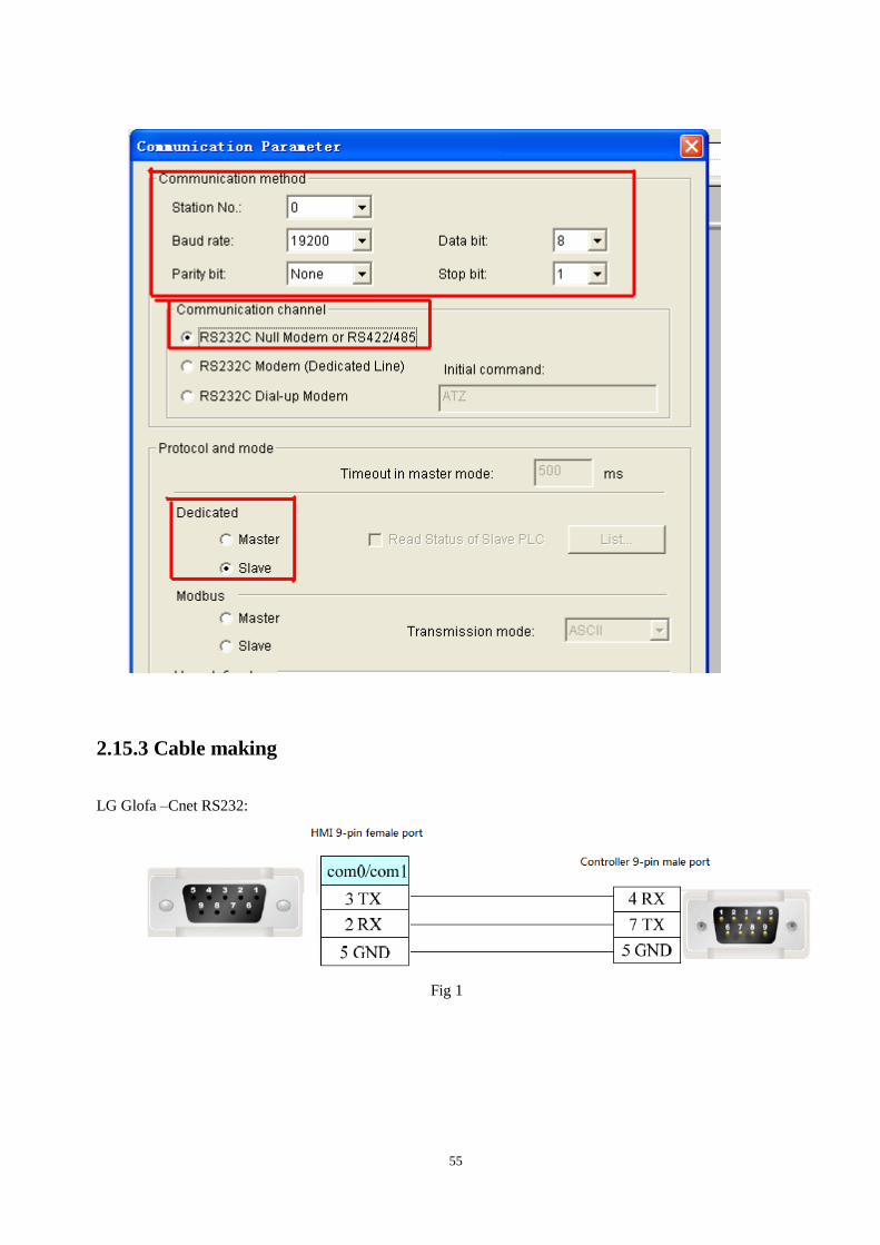
PLC:
Note:
1. Turn on the switch BUILT-IN CNET on the PLC.
2. “Dedicated-slave” must be choosed in the PLC programming software.
3. The communication area of M must be set in the PLC programming software.
M area size:
Protocol and mode settings:
54
55
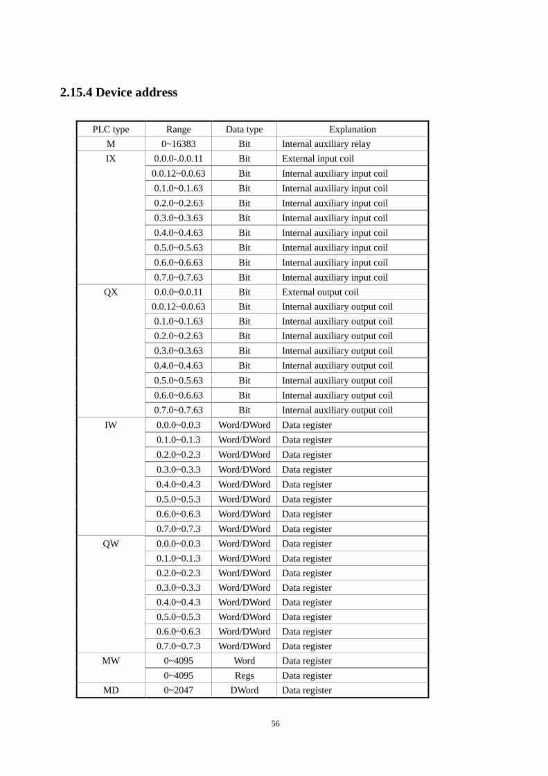
2.15.3 Cable making
LG Glofa –Cnet RS232:
Fig 1
56
2.15.4 Device address
PLC type Range Data type Explanation
M 0~16383 Bit Internal auxiliary relay
IX 0.0.0-.0.0.11 Bit External input coil
0.0.12~0.0.63 Bit Internal auxiliary input coil
0.1.0~0.1.63 Bit Internal auxiliary input coil
0.2.0~0.2.63 Bit Internal auxiliary input coil
0.3.0~0.3.63 Bit Internal auxiliary input coil
0.4.0~0.4.63 Bit Internal auxiliary input coil
0.5.0~0.5.63 Bit Internal auxiliary input coil
0.6.0~0.6.63 Bit Internal auxiliary input coil
0.7.0~0.7.63 Bit Internal auxiliary input coil
QX 0.0.0~0.0.11 Bit External output coil
0.0.12~0.0.63 Bit Internal auxiliary output coil
0.1.0~0.1.63 Bit Internal auxiliary output coil
0.2.0~0.2.63 Bit Internal auxiliary output coil
0.3.0~0.3.63 Bit Internal auxiliary output coil
0.4.0~0.4.63 Bit Internal auxiliary output coil
0.5.0~0.5.63 Bit Internal auxiliary output coil
0.6.0~0.6.63 Bit Internal auxiliary output coil
0.7.0~0.7.63 Bit Internal auxiliary output coil
IW 0.0.0~0.0.3 Word/DWord Data register
0.1.0~0.1.3 Word/DWord Data register
0.2.0~0.2.3 Word/DWord Data register
0.3.0~0.3.3 Word/DWord Data register
0.4.0~0.4.3 Word/DWord Data register
0.5.0~0.5.3 Word/DWord Data register
0.6.0~0.6.3 Word/DWord Data register
0.7.0~0.7.3 Word/DWord Data register
QW 0.0.0~0.0.3 Word/DWord Data register
0.1.0~0.1.3 Word/DWord Data register
0.2.0~0.2.3 Word/DWord Data register
0.3.0~0.3.3 Word/DWord Data register
0.4.0~0.4.3 Word/DWord Data register
0.5.0~0.5.3 Word/DWord Data register
0.6.0~0.6.3 Word/DWord Data register
0.7.0~0.7.3 Word/DWord Data register
MW 0~4095 Word Data register
0~4095 Regs Data register
MD 0~2047 DWord Data register

57
0~2038 Regs Data register
58
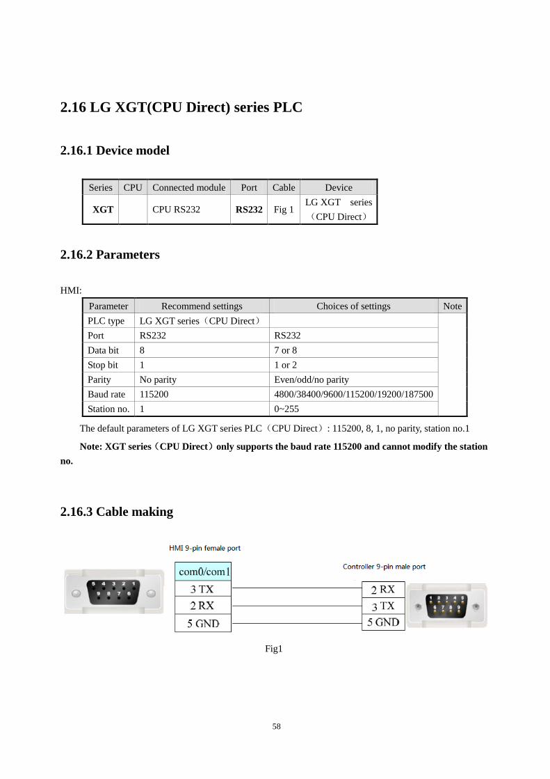
2.16 LG XGT(CPU Direct) series PLC
2.16.1 Device model
Series CPU Connected module Port Cable Device
XGT CPU RS232 RS232 Fig 1 LG XGT series
(CPU Direct)
2.16.2 Parameters
HMI:
Parameter Recommend settings Choices of settings Note
PLC type LG XGT series(CPU Direct)
Port RS232 RS232
Data bit 8 7 or 8
Stop bit 1 1 or 2
Parity No parity Even/odd/no parity
Baud rate 115200 4800/38400/9600/115200/19200/187500
Station no. 1 0~255
The default parameters of LG XGT series PLC(CPU Direct): 115200, 8, 1, no parity, station no.1
Note: XGT series(CPU Direct)only supports the baud rate 115200 and cannot modify the station
no.
2.16.3 Cable making
Fig1
59
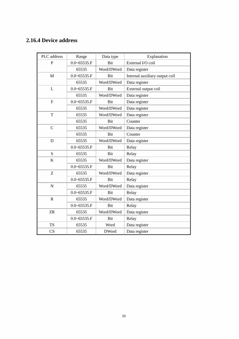
2.16.4 Device address
PLC address Range Data type Explanation
P 0.0~65535.F Bit External I/O coil
65535 Word/DWord Data register
M 0.0~65535.F Bit Internal auxiliary output coil
65535 Word/DWord Data register
L 0.0~65535.F Bit External output coil
65535 Word/DWord Data register
F 0.0~65535.F Bit Data register
65535 Word/DWord Data register
T 65535 Word/DWord Data register
65535 Bit Counter
C 65535 Word/DWord Data register
65535 Bit Counter
D 65535 Word/DWord Data register
0.0~65535.F Bit Relay
S 65535 Bit Relay
K 65535 Word/DWord Data register
0.0~65535.F Bit Relay
Z 65535 Word/DWord Data register
0.0~65535.F Bit Relay
N 65535 Word/DWord Data register
0.0~65535.F Bit Relay
R 65535 Word/DWord Data register
0.0~65535.F Bit Relay
ZR 65535 Word/DWord Data register
0.0~65535.F Bit Relay
TS 65535 Word Data register
CS 65535 DWord Data register
60
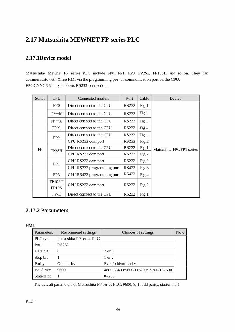
2.17 Matsushita MEWNET FP series PLC
2.17.1Device model
Matsushita- Mewnet FP series PLC include FP0, FP1, FP3, FP2SF, FP10SH and so on. They can
communicate with Xinje HMI via the programming port or communication port on the CPU.
FP0-CXXCXX only supports RS232 connection.
Series CPU Connected module Port Cable Device
FP
FP0 Direct connect to the CPU RS232 Fig 1
Matsushita FP0/FP1 series
FP-M Direct connect to the CPU RS232 Fig 1
FP-X Direct connect to the CPU RS232 Fig 1
FP∑ Direct connect to the CPU RS232 Fig 1
FP2 Direct connect to the CPU RS232 Fig 1
CPU RS232 com port RS232 Fig 2
FP2SH Direct connect to the CPU RS232 Fig 1
CPU RS232 com port RS232 Fig 2
FP1 CPU RS232 com port RS232 Fig 2
CPU RS232 programming port RS422 Fig 3
FP3 CPU RS422 programming port RS422 Fig 4
FP10SH
FP10S CPU RS232 com port RS232 Fig 2
FP-E Direct connect to the CPU RS232 Fig 1
2.17.2 Parameters
HMI:
Parameters Recommend settings Choices of settings Note
PLC type matsushita FP series PLC
Port RS232
Data bit 8 7 or 8
Stop bit 1 1 or 2
Parity Odd parity Even/odd/no parity
Baud rate 9600 4800/38400/9600/115200/19200/187500
Station no. 1 0~255
The default parameters of Matsushita FP series PLC: 9600, 8, 1, odd parity, station no.1
PLC:
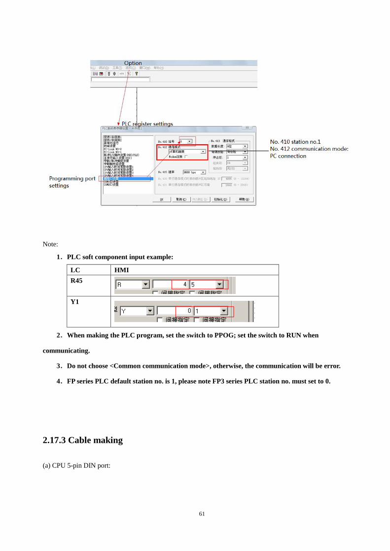
61
Note:
1.PLC soft component input example:
LC HMI
R45
Y1
2.When making the PLC program, set the switch to PPOG; set the switch to RUN when
communicating.
3.Do not choose <Common communication mode>, otherwise, the communication will be error.
4.FP series PLC default station no. is 1, please note FP3 series PLC station no. must set to 0.
2.17.3 Cable making
(a) CPU 5-pin DIN port:
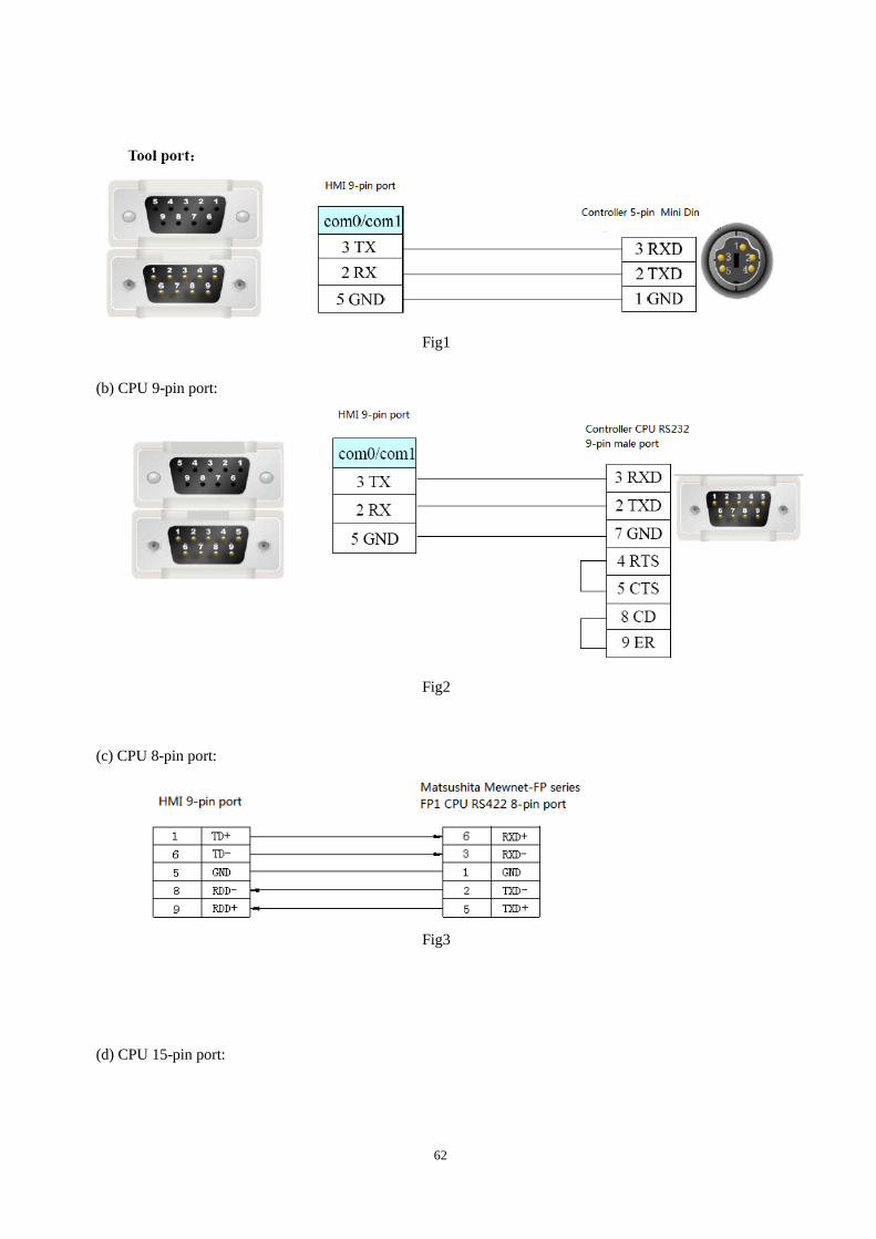
62
Fig1
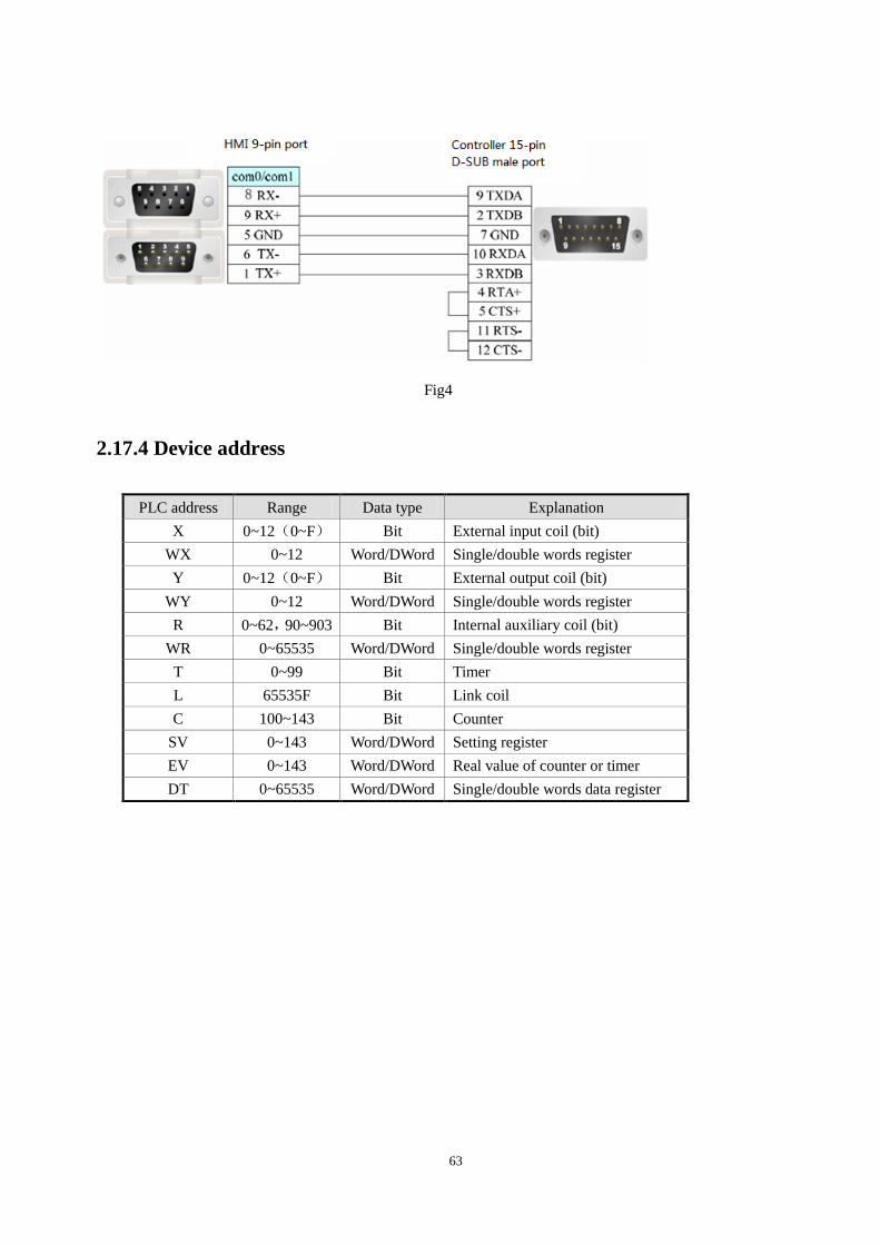
(b) CPU 9-pin port:
Fig2
(c) CPU 8-pin port:
Fig3
(d) CPU 15-pin port:
63
Fig4
2.17.4 Device address
PLC address Range Data type Explanation
X 0~12(0~F) Bit External input coil (bit)
WX 0~12 Word/DWord Single/double words register
Y 0~12(0~F) Bit External output coil (bit)
WY 0~12 Word/DWord Single/double words register
R 0~62,90~903 Bit Internal auxiliary coil (bit)
WR 0~65535 Word/DWord Single/double words register
T 0~99 Bit Timer
L 65535F Bit Link coil
C 100~143 Bit Counter
SV 0~143 Word/DWord Setting register
EV 0~143 Word/DWord Real value of counter or timer
DT 0~65535 Word/DWord Single/double words data register
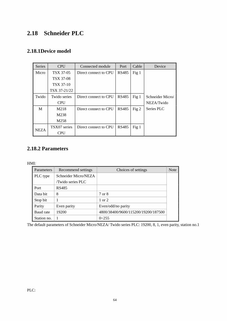
64
2.18 Schneider PLC
2.18.1Device model
Series CPU Connected module Port Cable Device
Micro TSX 37-05
TSX 37-08
TSX 37-10
TSX 37-21/22
Direct connect to CPU RS485 Fig 1
Schneider Micro/
NEZA/Twido
Series PLC
Twido Twido series
CPU
Direct connect to CPU RS485 Fig 1
M M218
M238
M258
Direct connect to CPU RS485 Fig 2
NEZA TSX07 series
CPU
Direct connect to CPU RS485 Fig 1
2.18.2 Parameters
HMI:
Parameters Recommend settings Choices of settings Note
PLC type Schneider Micro/NEZA
/Twido series PLC
Port RS485
Data bit 8 7 or 8
Stop bit 1 1 or 2
Parity Even parity Even/odd/no parity
Baud rate 19200 4800/38400/9600/115200/19200/187500
Station no. 1 0~255
The default parameters of Schneider Micro/NEZA/ Twido series PLC: 19200, 8, 1, even parity, station no.1
PLC:
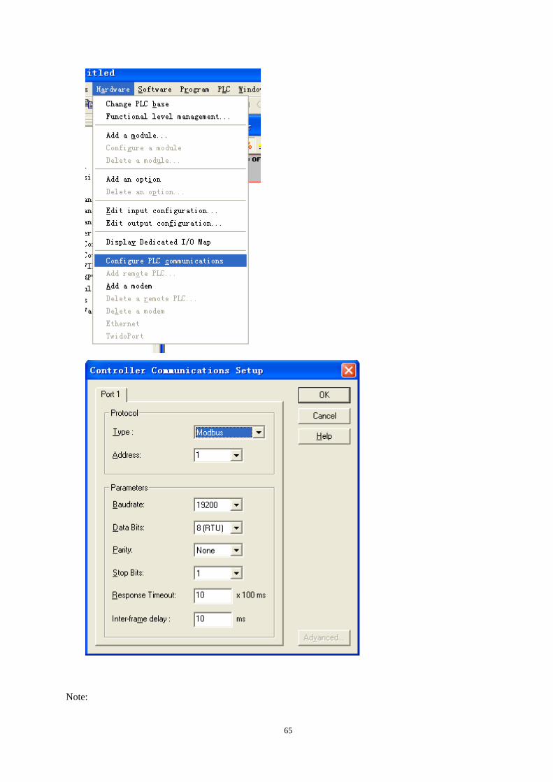
65
Note:
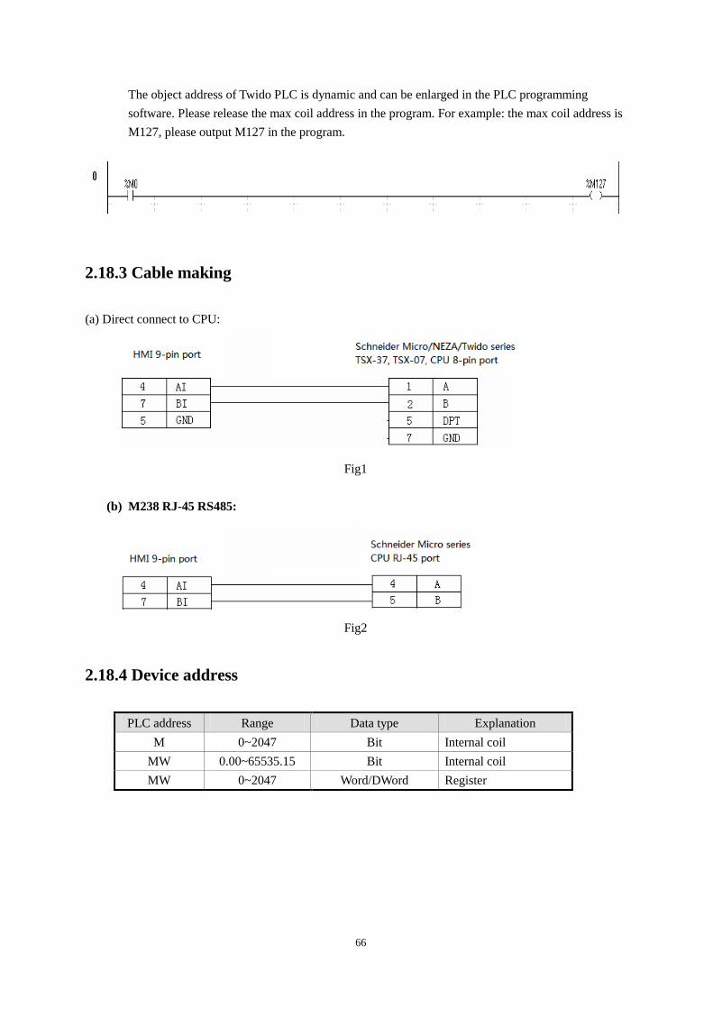
66
The object address of Twido PLC is dynamic and can be enlarged in the PLC programming
software. Please release the max coil address in the program. For example: the max coil address is
M127, please output M127 in the program.
2.18.3 Cable making
(a) Direct connect to CPU:
Fig1
(b) M238 RJ-45 RS485:
Fig2
2.18.4 Device address
PLC address Range Data type Explanation
M 0~2047 Bit Internal coil
MW 0.00~65535.15 Bit Internal coil
MW 0~2047 Word/DWord Register
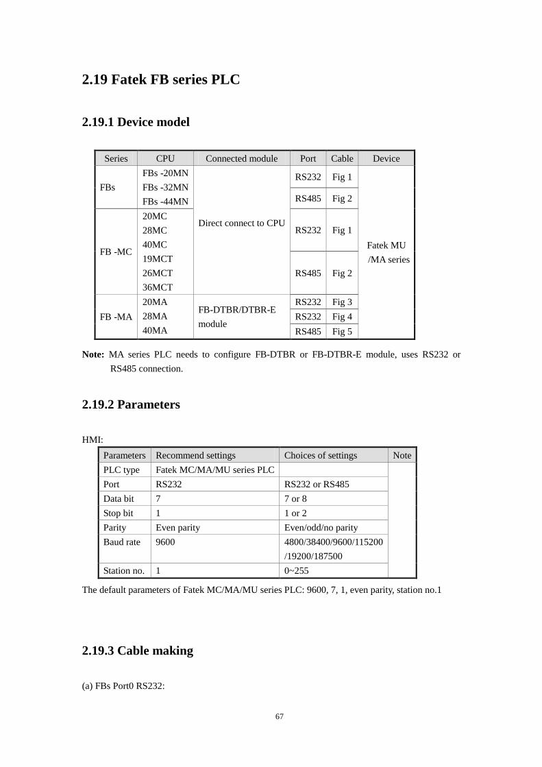
67
2.19 Fatek FB series PLC
2.19.1 Device model
Series CPU Connected module Port Cable Device
FBs
FBs -20MN
FBs -32MN
FBs -44MN
Direct connect to CPU
RS232 Fig 1
Fatek MU
/MA series
RS485 Fig 2
FB -MC
20MC
28MC
40MC
19MCT
26MCT
36MCT
RS232 Fig 1
RS485 Fig 2
FB -MA
20MA
28MA
40MA
FB-DTBR/DTBR-E
module
RS232 Fig 3
RS232 Fig 4
RS485 Fig 5
Note: MA series PLC needs to configure FB-DTBR or FB-DTBR-E module, uses RS232 or
RS485 connection.
2.19.2 Parameters
HMI:
Parameters Recommend settings Choices of settings Note
PLC type Fatek MC/MA/MU series PLC
Port RS232 RS232 or RS485
Data bit 7 7 or 8
Stop bit 1 1 or 2
Parity Even parity Even/odd/no parity
Baud rate 9600 4800/38400/9600/115200
/19200/187500
Station no. 1 0~255
The default parameters of Fatek MC/MA/MU series PLC: 9600, 7, 1, even parity, station no.1
2.19.3 Cable making
(a) FBs Port0 RS232:
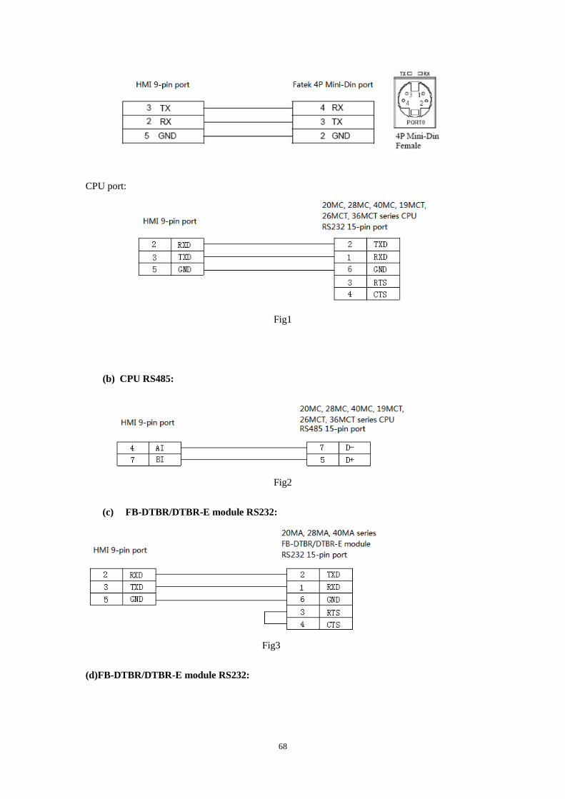
68
CPU port:
Fig1
(b) CPU RS485:
Fig2
(c) FB-DTBR/DTBR-E module RS232:
Fig3
(d)FB-DTBR/DTBR-E module RS232:
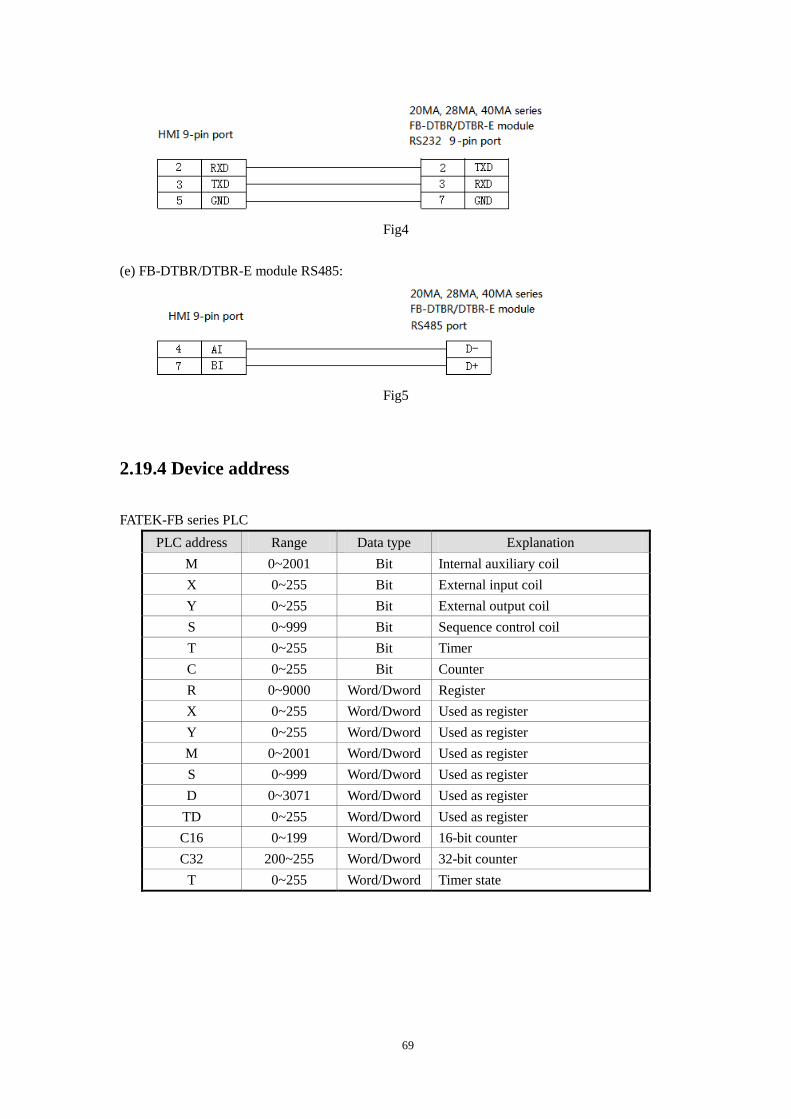
69
Fig4
(e) FB-DTBR/DTBR-E module RS485:
Fig5
2.19.4 Device address
FATEK-FB series PLC
PLC address Range Data type Explanation
M 0~2001 Bit Internal auxiliary coil
X 0~255 Bit External input coil
Y 0~255 Bit External output coil
S 0~999 Bit Sequence control coil
T 0~255 Bit Timer
C 0~255 Bit Counter
R 0~9000 Word/Dword Register
X 0~255 Word/Dword Used as register
Y 0~255 Word/Dword Used as register
M 0~2001 Word/Dword Used as register
S 0~999 Word/Dword Used as register
D 0~3071 Word/Dword Used as register
TD 0~255 Word/Dword Used as register
C16 0~199 Word/Dword 16-bit counter
C32 200~255 Word/Dword 32-bit counter
T 0~255 Word/Dword Timer state
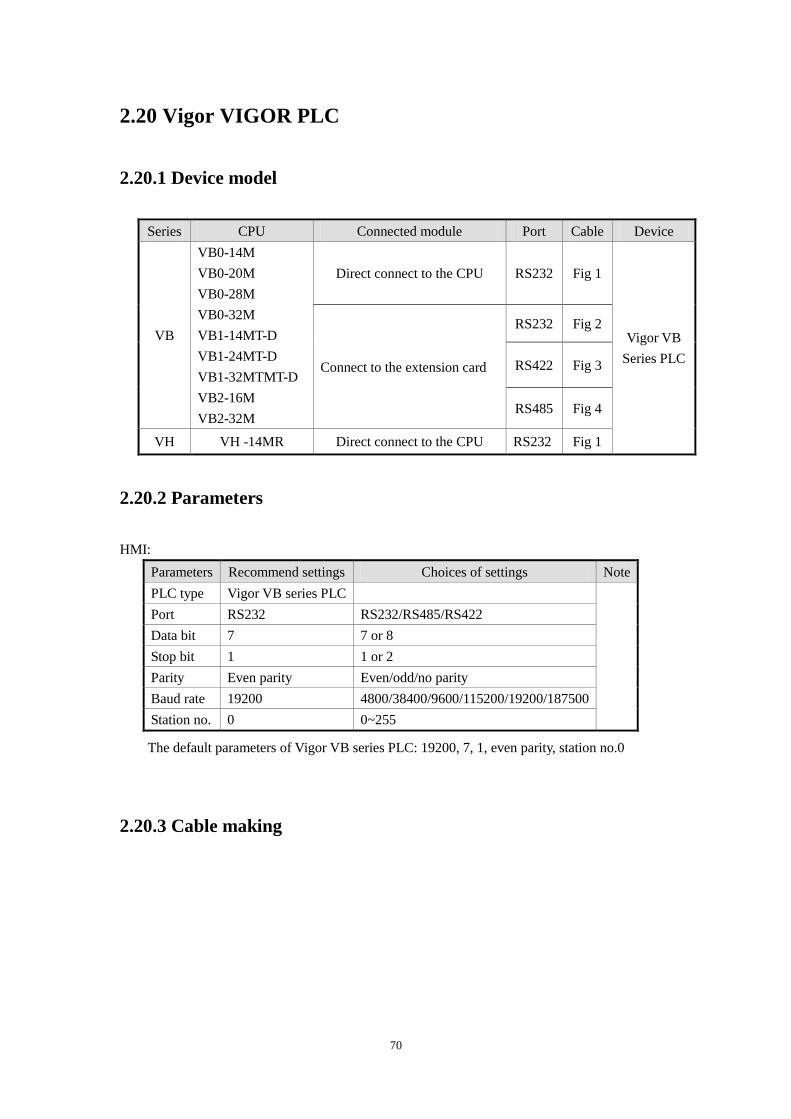
70
2.20 Vigor VIGOR PLC
2.20.1 Device model
Series CPU Connected module Port Cable Device
VB
VB0-14M
VB0-20M
VB0-28M
VB0-32M
VB1-14MT-D
VB1-24MT-D
VB1-32MTMT-D
VB2-16M
VB2-32M
Direct connect to the CPU RS232 Fig 1
Vigor VB
Series PLC Connect to the extension card
RS232 Fig 2
RS422 Fig 3
RS485 Fig 4
VH VH -14MR Direct connect to the CPU RS232 Fig 1
2.20.2 Parameters
HMI:
Parameters Recommend settings Choices of settings Note
PLC type Vigor VB series PLC
Port RS232 RS232/RS485/RS422
Data bit 7 7 or 8
Stop bit 1 1 or 2
Parity Even parity Even/odd/no parity
Baud rate 19200 4800/38400/9600/115200/19200/187500
Station no. 0 0~255
The default parameters of Vigor VB series PLC: 19200, 7, 1, even parity, station no.0
2.20.3 Cable making
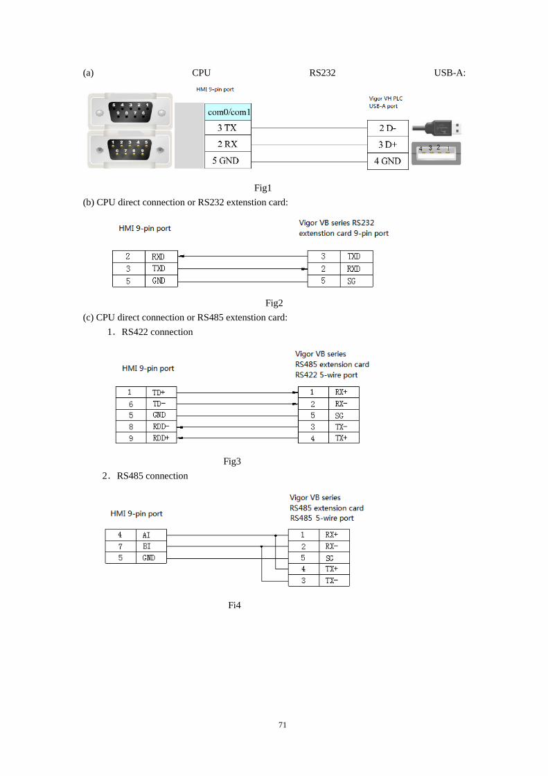
71
(a) CPU RS232 USB-A:
Fig1
(b) CPU direct connection or RS232 extenstion card:
Fig2
(c) CPU direct connection or RS485 extenstion card:
1.RS422 connection
Fig3
2.RS485 connection
Fi4
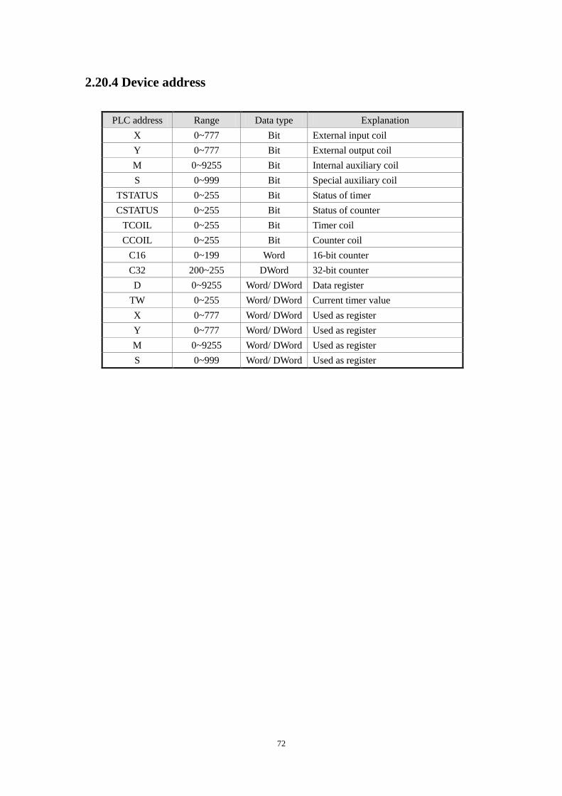
72
2.20.4 Device address
PLC address Range Data type Explanation
X 0~777 Bit External input coil
Y 0~777 Bit External output coil
M 0~9255 Bit Internal auxiliary coil
S 0~999 Bit Special auxiliary coil
TSTATUS 0~255 Bit Status of timer
CSTATUS 0~255 Bit Status of counter
TCOIL 0~255 Bit Timer coil
CCOIL 0~255 Bit Counter coil
C16 0~199 Word 16-bit counter
C32 200~255 DWord 32-bit counter
D 0~9255 Word/ DWord Data register
TW 0~255 Word/ DWord Current timer value
X 0~777 Word/ DWord Used as register
Y 0~777 Word/ DWord Used as register
M 0~9255 Word/ DWord Used as register
S 0~999 Word/ DWord Used as register
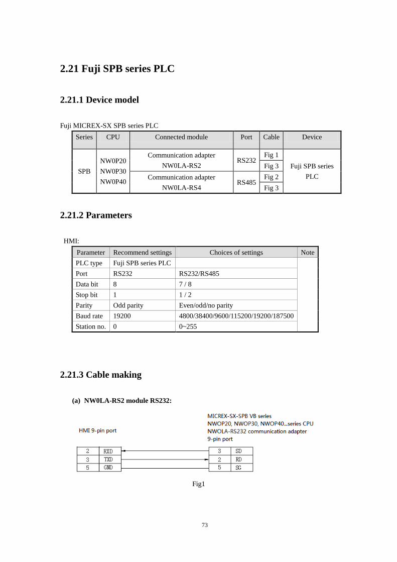
73
2.21 Fuji SPB series PLC
2.21.1 Device model
Fuji MICREX-SX SPB series PLC
Series CPU Connected module Port Cable Device
SPB
NW0P20
NW0P30
NW0P40
Communication adapter
NW0LA-RS2 RS232
Fig 1
Fuji SPB series
PLC
Fig 3
Communication adapter
NW0LA-RS4 RS485
Fig 2
Fig 3
2.21.2 Parameters
HMI:
Parameter Recommend settings Choices of settings Note
PLC type Fuji SPB series PLC
Port RS232 RS232/RS485
Data bit 8 7 / 8
Stop bit 1 1 / 2
Parity Odd parity Even/odd/no parity
Baud rate 19200 4800/38400/9600/115200/19200/187500
Station no. 0 0~255
2.21.3 Cable making
(a) NW0LA-RS2 module RS232:
Fig1
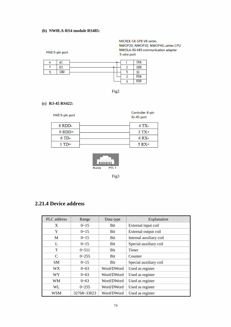
74
(b) NW0LA-RS4 module RS485:
Fig2
(c) RJ-45 RS422:
Fig3
2.21.4 Device address
PLC address Range Data type Explanation
X 0~15 Bit External input coil
Y 0~15 Bit External output coil
M 0~15 Bit Internal auxiliary coil
L 0~15 Bit Special auxiliary coil
T 0~511 Bit Timer
C 0~255 Bit Counter
SM 0~15 Bit Special auxiliary coil
WX 0~63 Word/DWord Used as register
WY 0~63 Word/DWord Used as register
WM 0~63 Word/DWord Used as register
WL 0~255 Word/DWord Used as register
WSM 32768~33023 Word/DWord Used as register
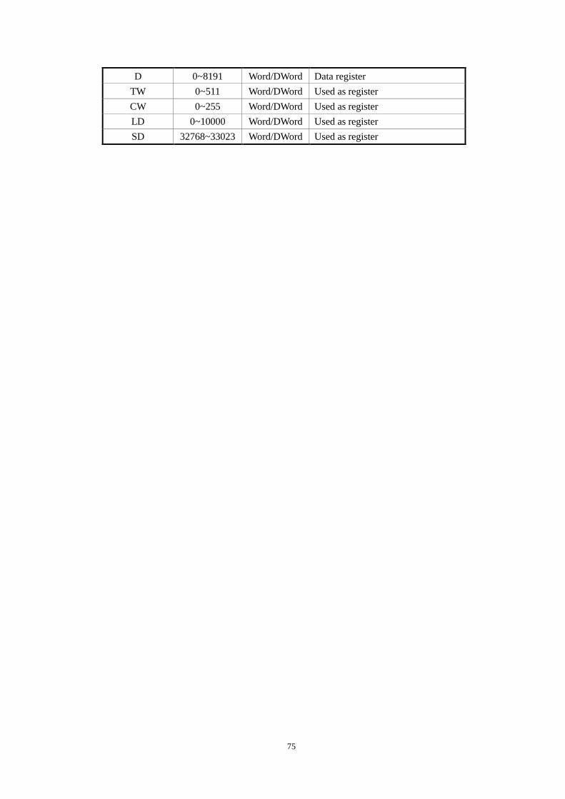
75
D 0~8191 Word/DWord Data register
TW 0~511 Word/DWord Used as register
CW 0~255 Word/DWord Used as register
LD 0~10000 Word/DWord Used as register
SD 32768~33023 Word/DWord Used as register
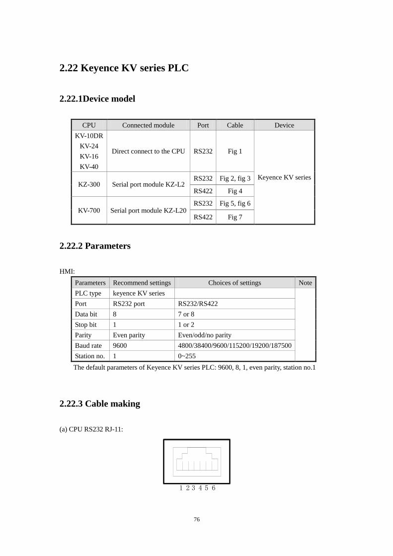
76
2.22 Keyence KV series PLC
2.22.1Device model
CPU Connected module Port Cable Device
KV-10DR
KV-24
KV-16
KV-40
Direct connect to the CPU RS232 Fig 1
Keyence KV series KZ-300 Serial port module KZ-L2
RS232 Fig 2, fig 3
RS422 Fig 4
KV-700 Serial port module KZ-L20 RS232 Fig 5, fig 6
RS422 Fig 7
2.22.2 Parameters
HMI:
Parameters Recommend settings Choices of settings Note
PLC type keyence KV series
Port RS232 port RS232/RS422
Data bit 8 7 or 8
Stop bit 1 1 or 2
Parity Even parity Even/odd/no parity
Baud rate 9600 4800/38400/9600/115200/19200/187500
Station no. 1 0~255
The default parameters of Keyence KV series PLC: 9600, 8, 1, even parity, station no.1
2.22.3 Cable making
(a) CPU RS232 RJ-11:
1 2 3 4 5 6
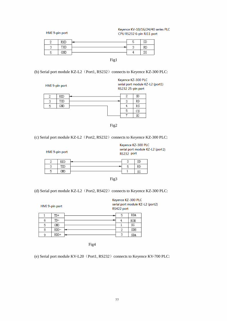
77
Fig1
(b) Serial port module KZ-L2(Port1, RS232)connects to Keyence KZ-300 PLC:
Fig2
(c) Serial port module KZ-L2(Port2, RS232)connects to Keyence KZ-300 PLC:
Fig3
(d) Serial port module KZ-L2(Port2, RS422)connects to Keyence KZ-300 PLC:
Fig4
(e) Serial port module KV-L20(Port1, RS232)connects to Keyence KV-700 PLC:
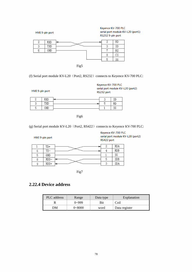
78
Fig5
(f) Serial port module KV-L20(Port2, RS232)connects to Keyence KV-700 PLC:
Fig6
(g) Serial port module KV-L20(Port2, RS422)connects to Keyence KV-700 PLC:
Fig7
2.22.4 Device address
PLC address Range Data type Explanation
R 0~999 Bit Coil
DM 0~8000 word Data register
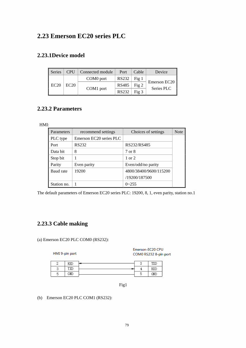
79
2.23 Emerson EC20 series PLC
2.23.1Device model
Series CPU Connected module Port Cable Device
EC20 EC20
COM0 port RS232 Fig 1 Emerson EC20
Series PLC COM1 port RS485 Fig 2
RS232 Fig 3
2.23.2 Parameters
HMI:
Parameters recommend settings Choices of settings Note
PLC type Emerson EC20 series PLC
Port RS232 RS232/RS485
Data bit 8 7 or 8
Stop bit 1 1 or 2
Parity Even parity Even/odd/no parity
Baud rate 19200 4800/38400/9600/115200
/19200/187500
Station no. 1 0~255
The default parameters of Emerson EC20 series PLC: 19200, 8, 1, even parity, station no.1
2.23.3 Cable making
(a) Emerson EC20 PLC COM0 (RS232):
Fig1
(b) Emerson EC20 PLC COM1 (RS232):
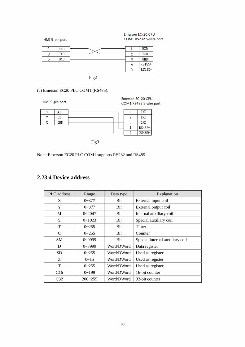
80
Fig2
(c) Emerson EC20 PLC COM1 (RS485):
Fig3
Note: Emerson EC20 PLC COM1 supports RS232 and RS485.
2.23.4 Device address
PLC address Range Data type Explanation
X 0~377 Bit External input coil
Y 0~377 Bit External output coil
M 0~2047 Bit Internal auxiliary coil
S 0~1023 Bit Special auxiliary coil
T 0~255 Bit Timer
C 0~255 Bit Counter
SM 0~9999 Bit Special internal auxiliary coil
D 0~7999 Word/DWord Data register
SD 0~255 Word/DWord Used as register
Z 0~15 Word/DWord Used as register
T 0~255 Word/DWord Used as register
C16 0~199 Word/DWord 16-bit counter
C32 200~255 Word/DWord 32-bit counter
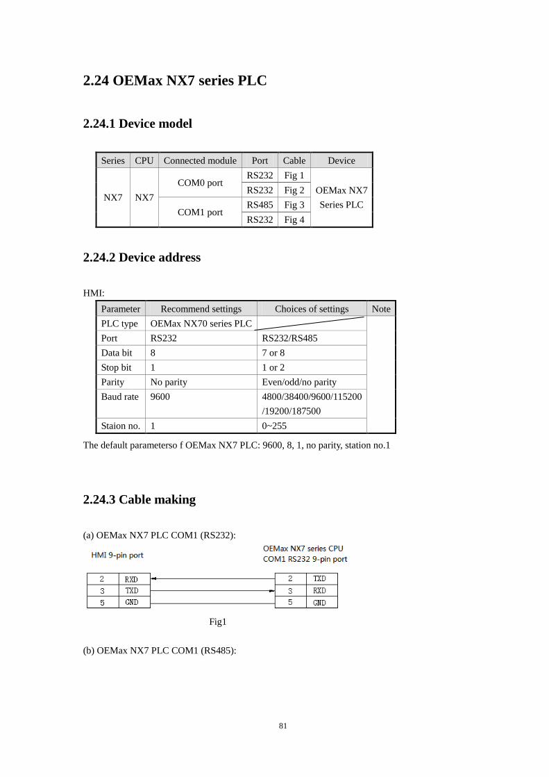
81
2.24 OEMax NX7 series PLC
2.24.1 Device model
Series CPU Connected module Port Cable Device
NX7 NX7
COM0 port RS232 Fig 1
OEMax NX7
Series PLC
RS232 Fig 2
COM1 port RS485 Fig 3
RS232 Fig 4
2.24.2 Device address
HMI:
Parameter Recommend settings Choices of settings Note
PLC type OEMax NX70 series PLC
Port RS232 RS232/RS485
Data bit 8 7 or 8
Stop bit 1 1 or 2
Parity No parity Even/odd/no parity
Baud rate 9600 4800/38400/9600/115200
/19200/187500
Staion no. 1 0~255
The default parameterso f OEMax NX7 PLC: 9600, 8, 1, no parity, station no.1
2.24.3 Cable making
(a) OEMax NX7 PLC COM1 (RS232):
Fig1
(b) OEMax NX7 PLC COM1 (RS485):
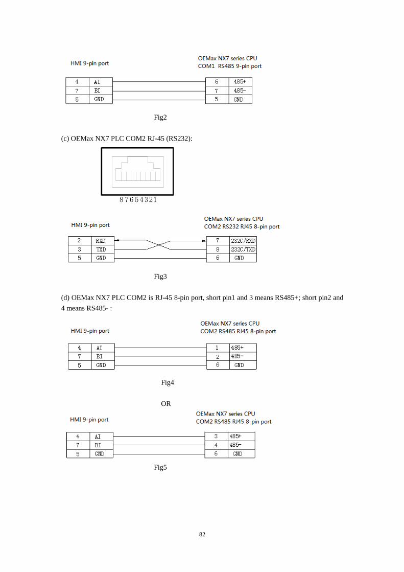
82
Fig2
(c) OEMax NX7 PLC COM2 RJ-45 (RS232):
12345678
Fig3
(d) OEMax NX7 PLC COM2 is RJ-45 8-pin port, short pin1 and 3 means RS485+; short pin2 and
4 means RS485- :
Fig4
OR
Fig5
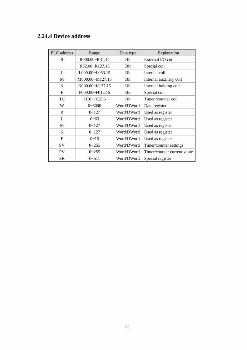
83
2.24.4 Device address
PLC address Range Data type Explanation
R R000.00~R31.15 Bit External I/O coil
R32.00~R127.15 Bit Special coil
L L000.00~L063.15 Bit Internal coil
M M000.00~M127.15 Bit Internal auxiliary coil
K K000.00~K127.15 Bit Internal holding coil
F F000.00~F015.15 Bit Special coil
TC TC0~TC255 Bit Timer /counter coil
W 0~6000 Word/DWord Data register
R 0~127 Word/DWord Used as register
L 0~63 Word/DWord Used as register
M 0~127 Word/DWord Used as register
K 0~127 Word/DWord Used as register
F 0~15 Word/DWord Used as register
SV 0~255 Word/DWord Timer/counter settings
PV 0~255 Word/DWord Timer/counter current value
SR 0~511 Word/DWord Special register
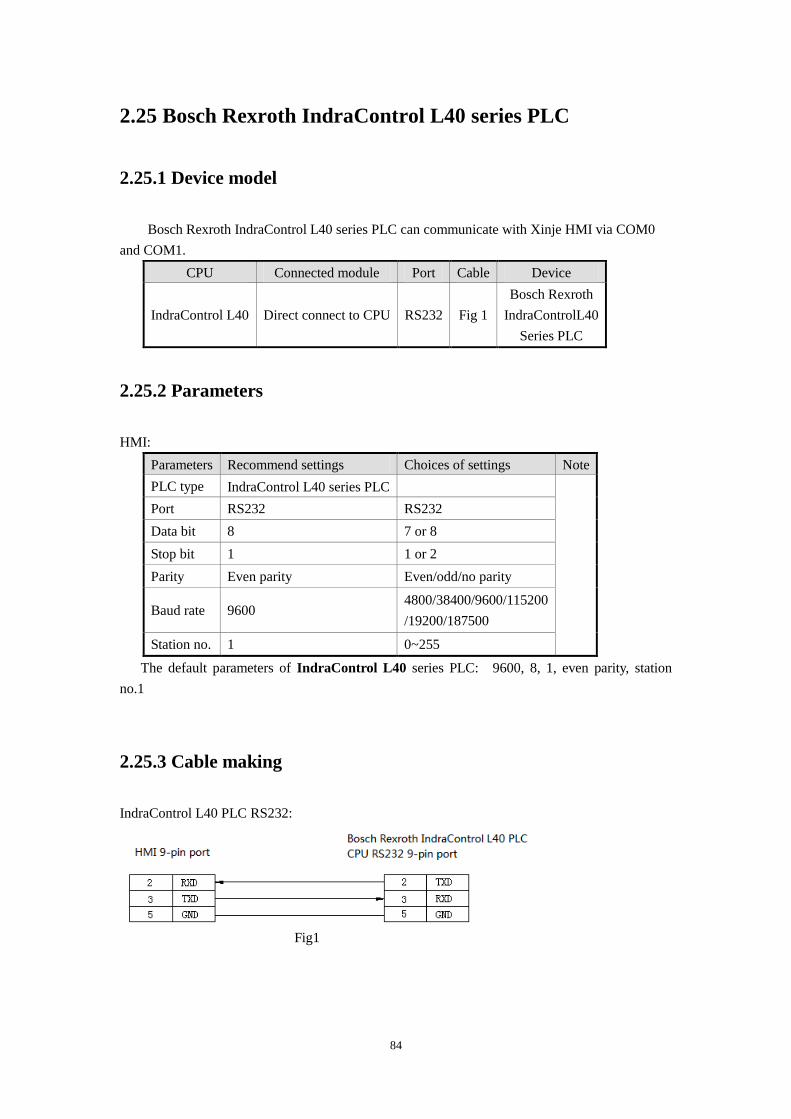
84
2.25 Bosch Rexroth IndraControl L40 series PLC
2.25.1 Device model
Bosch Rexroth IndraControl L40 series PLC can communicate with Xinje HMI via COM0
and COM1.
CPU Connected module Port Cable Device
IndraControl L40 Direct connect to CPU RS232 Fig 1
Bosch Rexroth
IndraControlL40
Series PLC
2.25.2 Parameters
HMI:
Parameters Recommend settings Choices of settings Note
PLC type IndraControl L40 series PLC
Port RS232 RS232
Data bit 8 7 or 8
Stop bit 1 1 or 2
Parity Even parity Even/odd/no parity
Baud rate 9600 4800/38400/9600/115200
/19200/187500
Station no. 1 0~255
The default parameters of IndraControl L40 series PLC: 9600, 8, 1, even parity, station
no.1
2.25.3 Cable making
IndraControl L40 PLC RS232:
Fig1
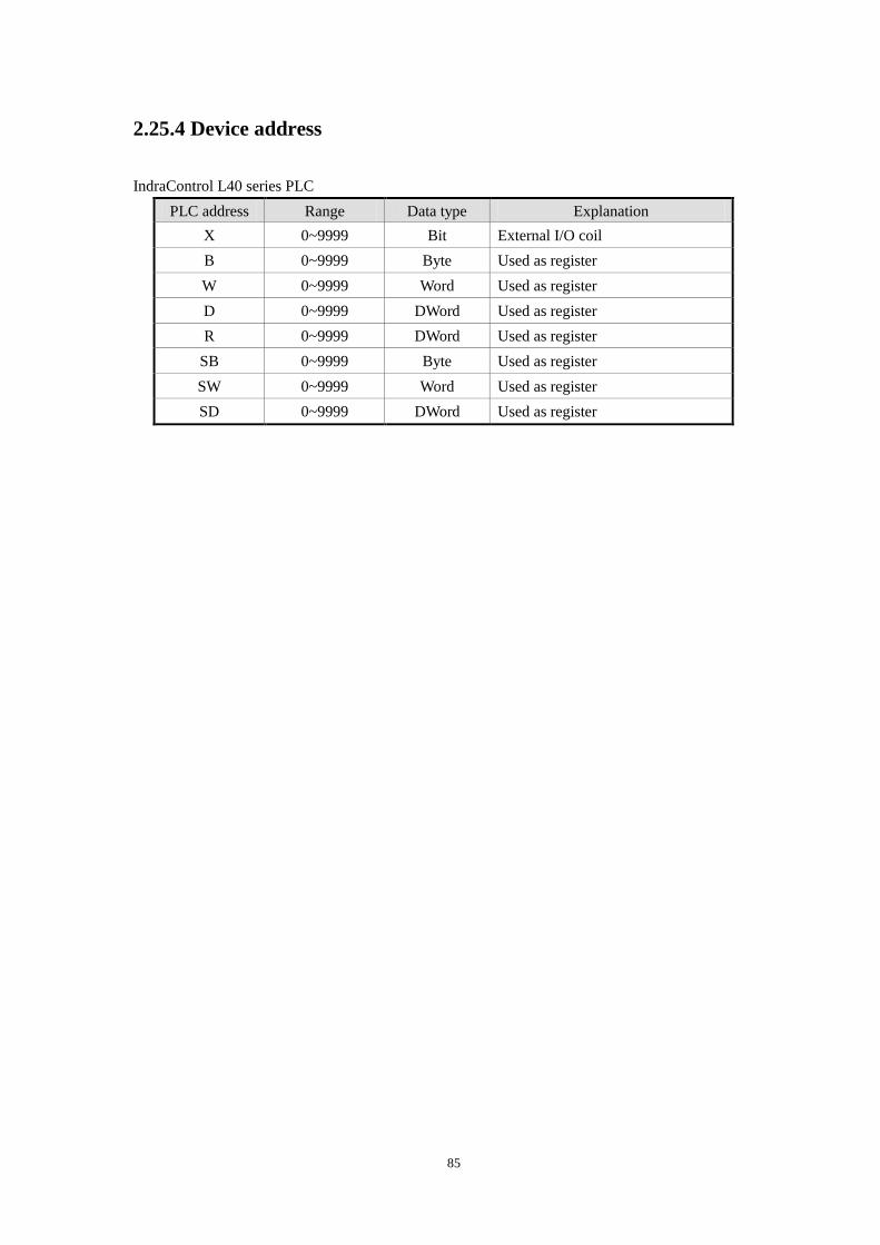
85
2.25.4 Device address
IndraControl L40 series PLC
PLC address Range Data type Explanation
X 0~9999 Bit External I/O coil
B 0~9999 Byte Used as register
W 0~9999 Word Used as register
D 0~9999 DWord Used as register
R 0~9999 DWord Used as register
SB 0~9999 Byte Used as register
SW 0~9999 Word Used as register
SD 0~9999 DWord Used as register
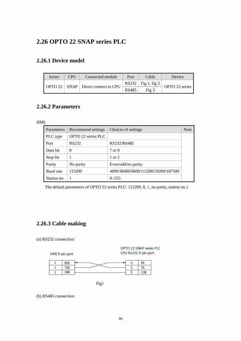
86
2.26 OPTO 22 SNAP series PLC
2.26.1 Device model
Series CPU Connected module Port Cable Device
OPTO 22 SNAP Direct connect to CPU RS232 Fig 1, fig 2
OPTO 22 series RS485 Fig 3
2.26.2 Parameters
HMI:
Parameters Recommend settings Choices of settings Note
PLC type OPTO 22 series PLC
Port RS232 RS232/RS485
Data bit 8 7 or 8
Stop bit 1 1 or 2
Parity No parity Even/odd/no parity
Baud rate 115200 4800/38400/9600/115200/19200/187500
Station no. 1 0~255
The default parameters of OPTO 22 series PLC: 115200, 8, 1, no parity, station no.1
2.26.3 Cable making
(a) RS232 connection:
Fig1
(b) RS485 connection:
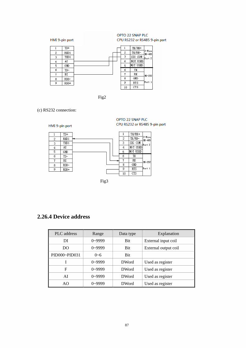
87
Fig2
(c) RS232 connection:
Fig3
2.26.4 Device address
PLC address Range Data type Explanation
DI 0~9999 Bit External input coil
DO 0~9999 Bit External output coil
PID000~PID031 0~6 Bit
I 0~9999 DWord Used as register
F 0~9999 DWord Used as register
AI 0~9999 DWord Used as register
AO 0~9999 DWord Used as register
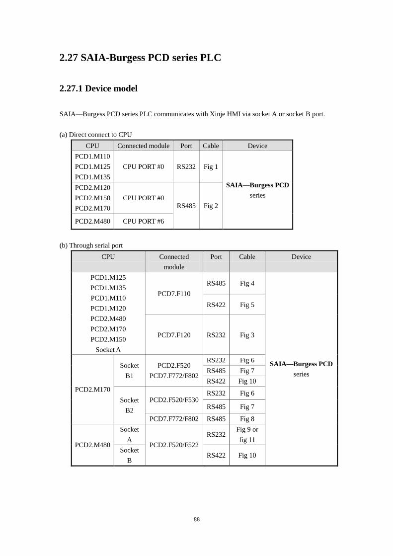
88
2.27 SAIA-Burgess PCD series PLC
2.27.1 Device model
SAIA—Burgess PCD series PLC communicates with Xinje HMI via socket A or socket B port.
(a) Direct connect to CPU
CPU Connected module Port Cable Device
PCD1.M110
PCD1.M125
PCD1.M135
CPU PORT #0 RS232 Fig 1
SAIA—Burgess PCD
series PCD2.M120
PCD2.M150
PCD2.M170
CPU PORT #0 RS485 Fig 2
PCD2.M480 CPU PORT #6
(b) Through serial port
CPU Connected
module
Port Cable Device
PCD1.M125
PCD1.M135
PCD1.M110
PCD1.M120
PCD2.M480
PCD2.M170
PCD2.M150
Socket A
PCD7.F110
RS485 Fig 4
SAIA—Burgess PCD
series
RS422 Fig 5
PCD7.F120 RS232 Fig 3
PCD2.M170
Socket
B1
PCD2.F520
PCD7.F772/F802
RS232 Fig 6
RS485 Fig 7
RS422 Fig 10
Socket
B2
PCD2.F520/F530 RS232 Fig 6
RS485 Fig 7
PCD7.F772/F802 RS485 Fig 8
PCD2.M480
Socket
A PCD2.F520/F522
RS232 Fig 9 or
fig 11
Socket
B RS422 Fig 10
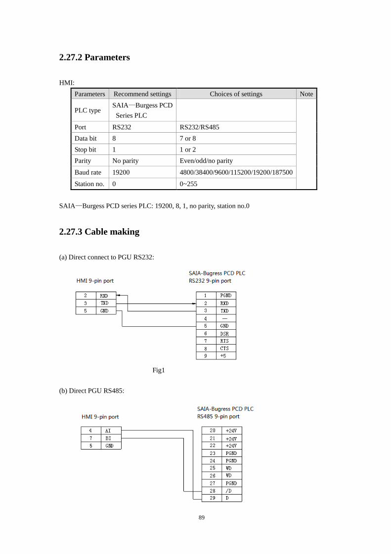
89
2.27.2 Parameters
HMI:
Parameters Recommend settings Choices of settings Note
PLC type SAIA—Burgess PCD
Series PLC
Port RS232 RS232/RS485
Data bit 8 7 or 8
Stop bit 1 1 or 2
Parity No parity Even/odd/no parity
Baud rate 19200 4800/38400/9600/115200/19200/187500
Station no. 0 0~255
SAIA—Burgess PCD series PLC: 19200, 8, 1, no parity, station no.0
2.27.3 Cable making
(a) Direct connect to PGU RS232:
Fig1
(b) Direct PGU RS485:
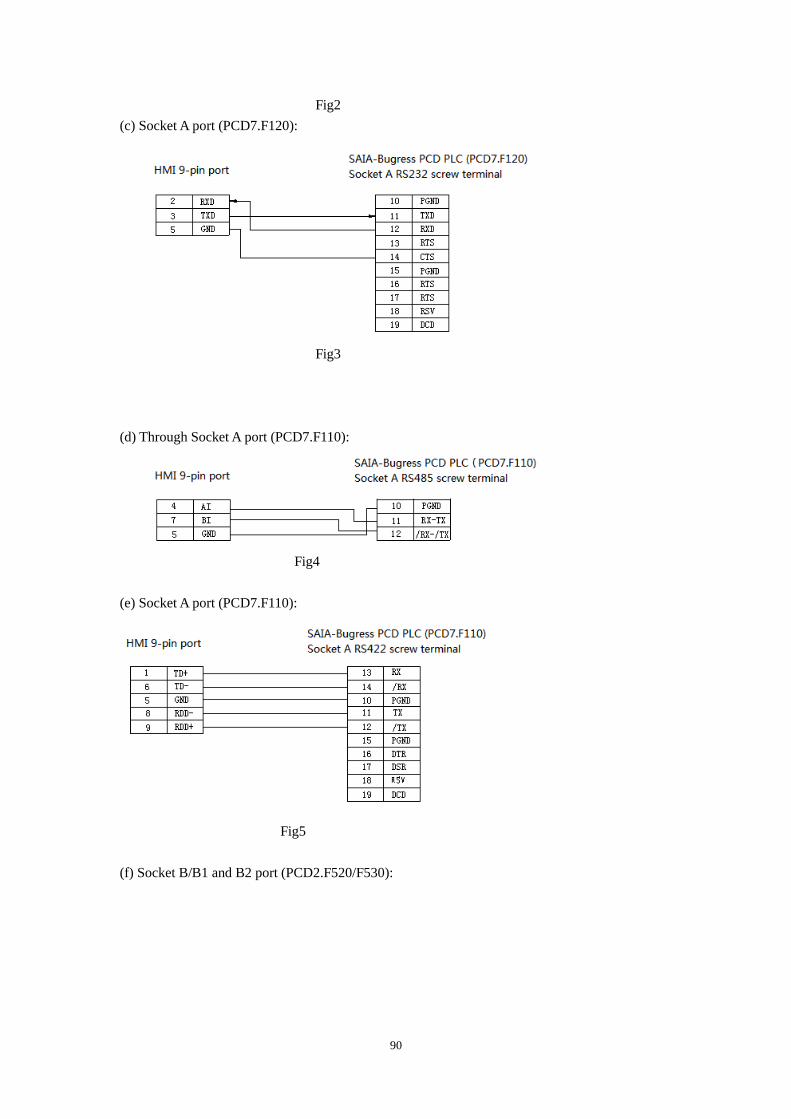
90
Fig2
(c) Socket A port (PCD7.F120):
Fig3
(d) Through Socket A port (PCD7.F110):
Fig4
(e) Socket A port (PCD7.F110):
Fig5
(f) Socket B/B1 and B2 port (PCD2.F520/F530):
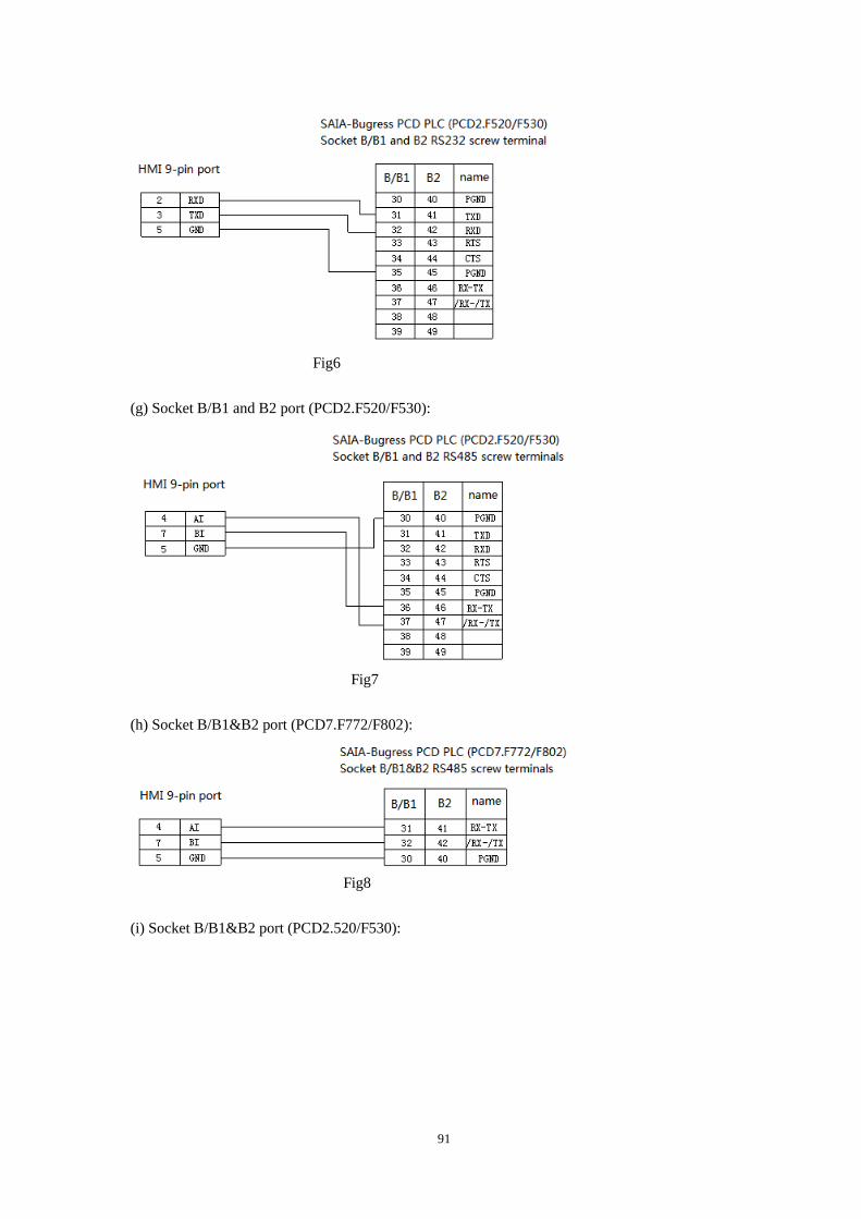
91
Fig6
(g) Socket B/B1 and B2 port (PCD2.F520/F530):
Fig7
(h) Socket B/B1&B2 port (PCD7.F772/F802):
Fig8
(i) Socket B/B1&B2 port (PCD2.520/F530):
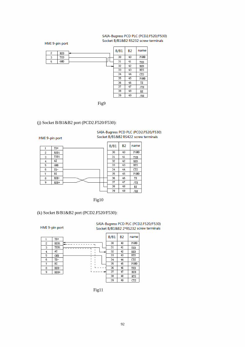
92
Fig9
(j) Socket B/B1&B2 port (PCD2.F520/F530):
Fig10
(k) Socket B/B1&B2 port (PCD2.F520/F530):
Fig11
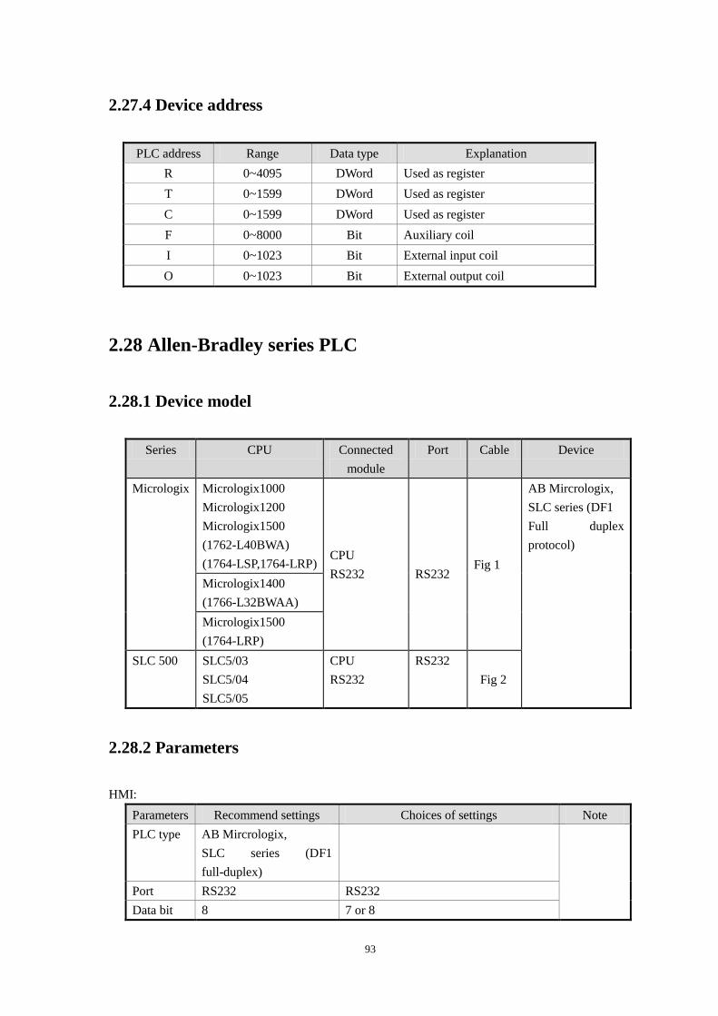
93
2.27.4 Device address
PLC address Range Data type Explanation
R 0~4095 DWord Used as register
T 0~1599 DWord Used as register
C 0~1599 DWord Used as register
F 0~8000 Bit Auxiliary coil
I 0~1023 Bit External input coil
O 0~1023 Bit External output coil
2.28 Allen-Bradley series PLC
2.28.1 Device model
Series CPU Connected
module
Port Cable Device
Micrologix Micrologix1000
Micrologix1200
Micrologix1500
(1762-L40BWA)
(1764-LSP,1764-LRP) CPU
RS232
RS232 Fig 1
AB Mircrologix,
SLC series (DF1
Full duplex
protocol)
Micrologix1400
(1766-L32BWAA)
Micrologix1500
(1764-LRP)
SLC 500 SLC5/03
SLC5/04
SLC5/05
CPU
RS232
RS232
Fig 2
2.28.2 Parameters
HMI:
Parameters Recommend settings Choices of settings Note
PLC type AB Mircrologix,
SLC series (DF1
full-duplex)
Port RS232 RS232
Data bit 8 7 or 8
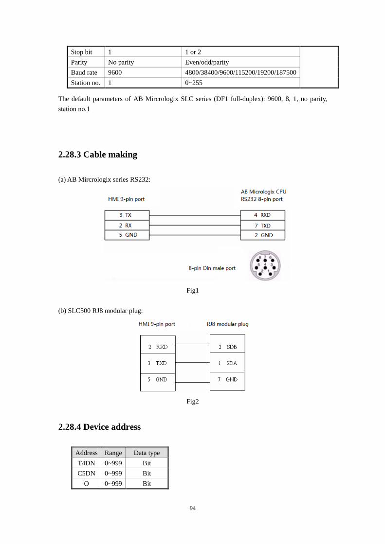
94
Stop bit 1 1 or 2
Parity No parity Even/odd/parity
Baud rate 9600 4800/38400/9600/115200/19200/187500
Station no. 1 0~255
The default parameters of AB Mircrologix SLC series (DF1 full-duplex): 9600, 8, 1, no parity,
station no.1
2.28.3 Cable making
(a) AB Mircrologix series RS232:
Fig1
(b) SLC500 RJ8 modular plug:
Fig2
2.28.4 Device address
Address Range Data type
T4DN 0~999 Bit
C5DN 0~999 Bit
O 0~999 Bit
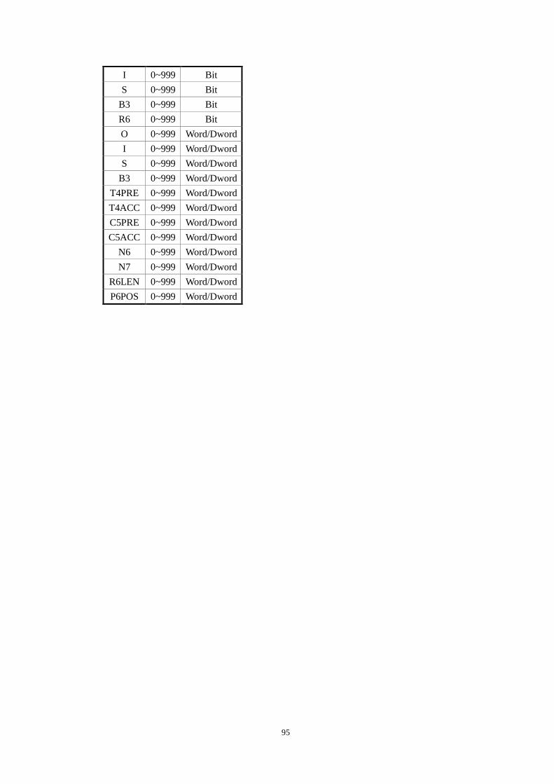
95
I 0~999 Bit
S 0~999 Bit
B3 0~999 Bit
R6 0~999 Bit
O 0~999 Word/Dword
I 0~999 Word/Dword
S 0~999 Word/Dword
B3 0~999 Word/Dword
T4PRE 0~999 Word/Dword
T4ACC 0~999 Word/Dword
C5PRE 0~999 Word/Dword
C5ACC 0~999 Word/Dword
N6 0~999 Word/Dword
N7 0~999 Word/Dword
R6LEN 0~999 Word/Dword
P6POS 0~999 Word/Dword
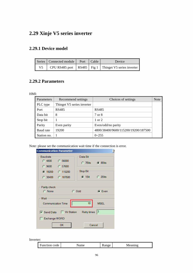
96
2.29 Xinje V5 series inverter
2.29.1 Device model
Series Connected module Port Cable Device
V5 CPU RS485 port RS485 Fig 1 Thinget V5 series inverter
2.29.2 Parameters
HMI:
Parameters Recommend settings Choices of settings Note
PLC type Thinget V5 series inverter
Port RS485 RS485
Data bit 8 7 or 8
Stop bit 1 1 or 2
Parity Even parity Even/odd/no parity
Baud rate 19200 4800/38400/9600/115200/19200/187500
Station no. 1 0~255
Note: please set the communication wait time if the connection is error.
Inverter:
Function code Name Range Meaning
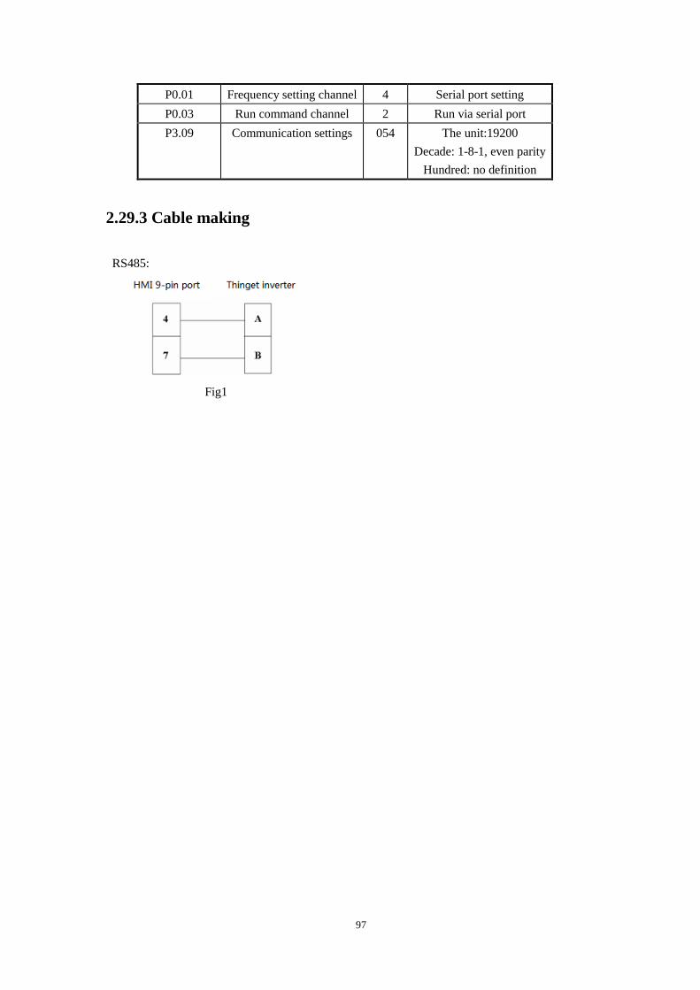
97
P0.01 Frequency setting channel 4 Serial port setting
P0.03 Run command channel 2 Run via serial port
P3.09 Communication settings 054 The unit:19200
Decade: 1-8-1, even parity
Hundred: no definition
2.29.3 Cable making
RS485:
Fig1
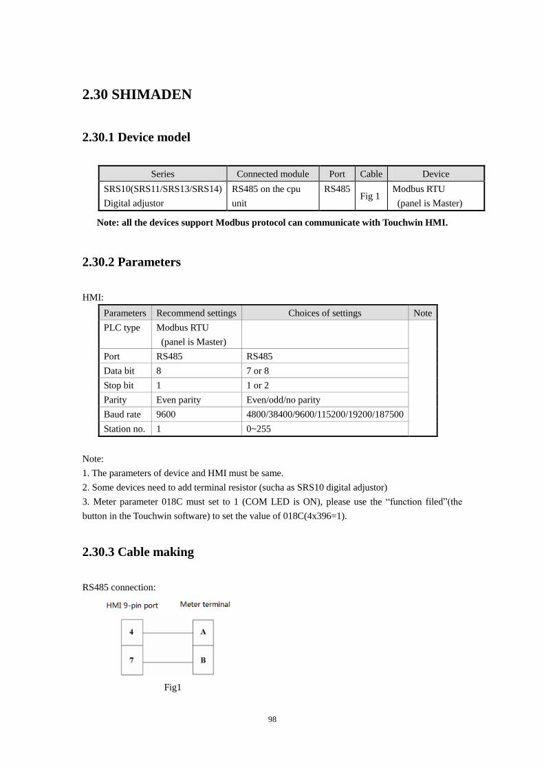
98
2.30 SHIMADEN
2.30.1 Device model
Series Connected module Port Cable Device
SRS10(SRS11/SRS13/SRS14)
Digital adjustor
RS485 on the cpu
unit
RS485 Fig 1
Modbus RTU
(panel is Master)
Note: all the devices support Modbus protocol can communicate with Touchwin HMI.
2.30.2 Parameters
HMI:
Parameters Recommend settings Choices of settings Note
PLC type Modbus RTU
(panel is Master)
Port RS485 RS485
Data bit 8 7 or 8
Stop bit 1 1 or 2
Parity Even parity Even/odd/no parity
Baud rate 9600 4800/38400/9600/115200/19200/187500
Station no. 1 0~255
Note:
1. The parameters of device and HMI must be same.
2. Some devices need to add terminal resistor (sucha as SRS10 digital adjustor)
3. Meter parameter 018C must set to 1 (COM LED is ON), please use the “function filed”(the
button in the Touchwin software) to set the value of 018C(4x396=1).
2.30.3 Cable making
RS485 connection:
Fig1
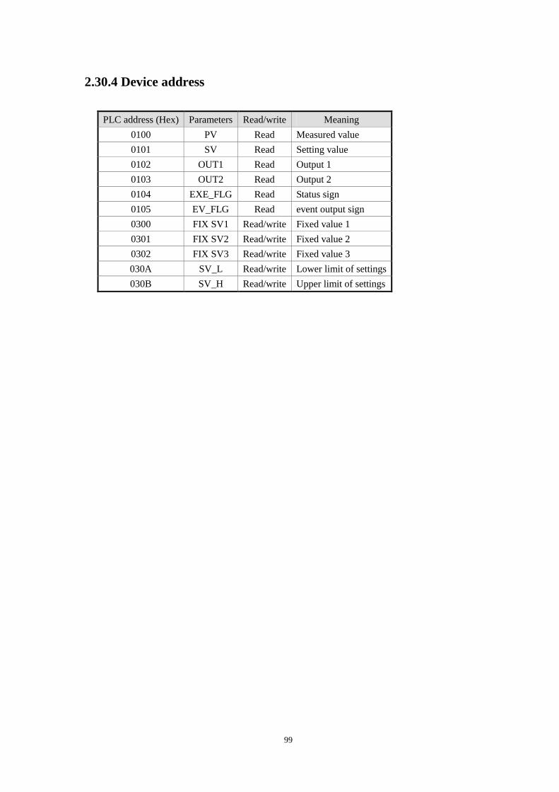
99
2.30.4 Device address
PLC address (Hex) Parameters Read/write Meaning
0100 PV Read Measured value
0101 SV Read Setting value
0102 OUT1 Read Output 1
0103 OUT2 Read Output 2
0104 EXE_FLG Read Status sign
0105 EV_FLG Read event output sign
0300 FIX SV1 Read/write Fixed value 1
0301 FIX SV2 Read/write Fixed value 2
0302 FIX SV3 Read/write Fixed value 3
030A SV_L Read/write Lower limit of settings
030B SV_H Read/write Upper limit of settings
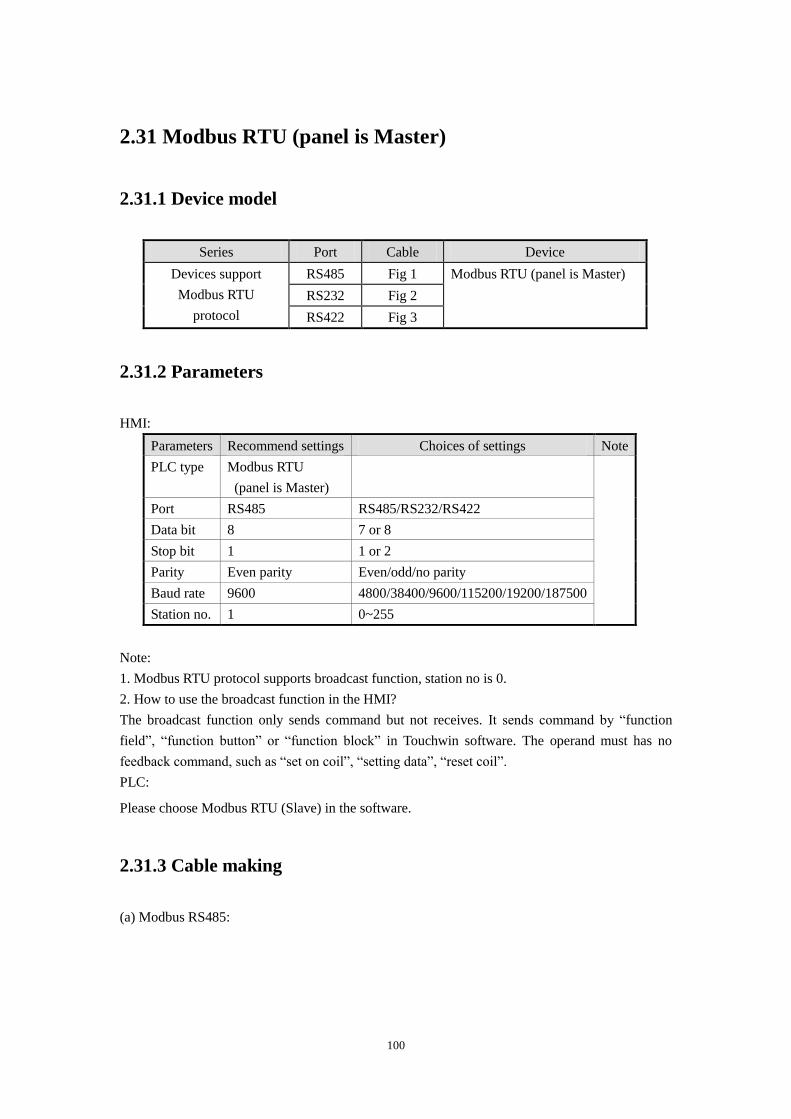
100
2.31 Modbus RTU (panel is Master)
2.31.1 Device model
Series Port Cable Device
Devices support
Modbus RTU
protocol
RS485 Fig 1 Modbus RTU (panel is Master)
RS232 Fig 2
RS422 Fig 3
2.31.2 Parameters
HMI:
Parameters Recommend settings Choices of settings Note
PLC type Modbus RTU
(panel is Master)
Port RS485 RS485/RS232/RS422
Data bit 8 7 or 8
Stop bit 1 1 or 2
Parity Even parity Even/odd/no parity
Baud rate 9600 4800/38400/9600/115200/19200/187500
Station no. 1 0~255
Note:
1. Modbus RTU protocol supports broadcast function, station no is 0.
2. How to use the broadcast function in the HMI?
The broadcast function only sends command but not receives. It sends command by “function
field”, “function button” or “function block” in Touchwin software. The operand must has no
feedback command, such as “set on coil”, “setting data”, “reset coil”.
PLC:
Please choose Modbus RTU (Slave) in the software.
2.31.3 Cable making
(a) Modbus RS485:
101
Fig1
(b) Modbus RS232:
Fig2
(c) Modbus RS422:
Fig3
2.31.4 Device address
Device address Range Data type Feature Explanation
0x 0~65535 Bit R/W External I/O /internal coil
1x 0~65535 Bit R External I/O /internal coil
4x 0~65535(0~15) Bit R/W External I/O /internal coil
4x 0~65535 Word/Dword R/W Used as data register
3x 0~65535 Word/Dword R Used as data register
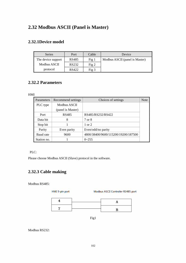
102
2.32 Modbus ASCII (Panel is Master)
2.32.1Device model
Series Port Cable Device
The device support
Modbus ASCII
protocol
RS485 Fig 1 Modbus ASCII (panel is Master)
RS232 Fig 2
RS422 Fig 3
2.32.2 Parameters
HMI
Parameters Recommend settings Choices of settings Note
PLC type Modbus ASCII
(panel is Master)
Port RS485 RS485/RS232/RS422
Data bit 8 7 or 8
Stop bit 1 1 or 2
Parity Even parity Even/odd/no parity
Baud rate 9600 4800/38400/9600/115200/19200/187500
Station no. 1 0~255
PLC:
Please choose Modbus ASCII (Slave) protocol in the software.
2.32.3 Cable making
Modbus RS485:
Fig1
Modbus RS232:
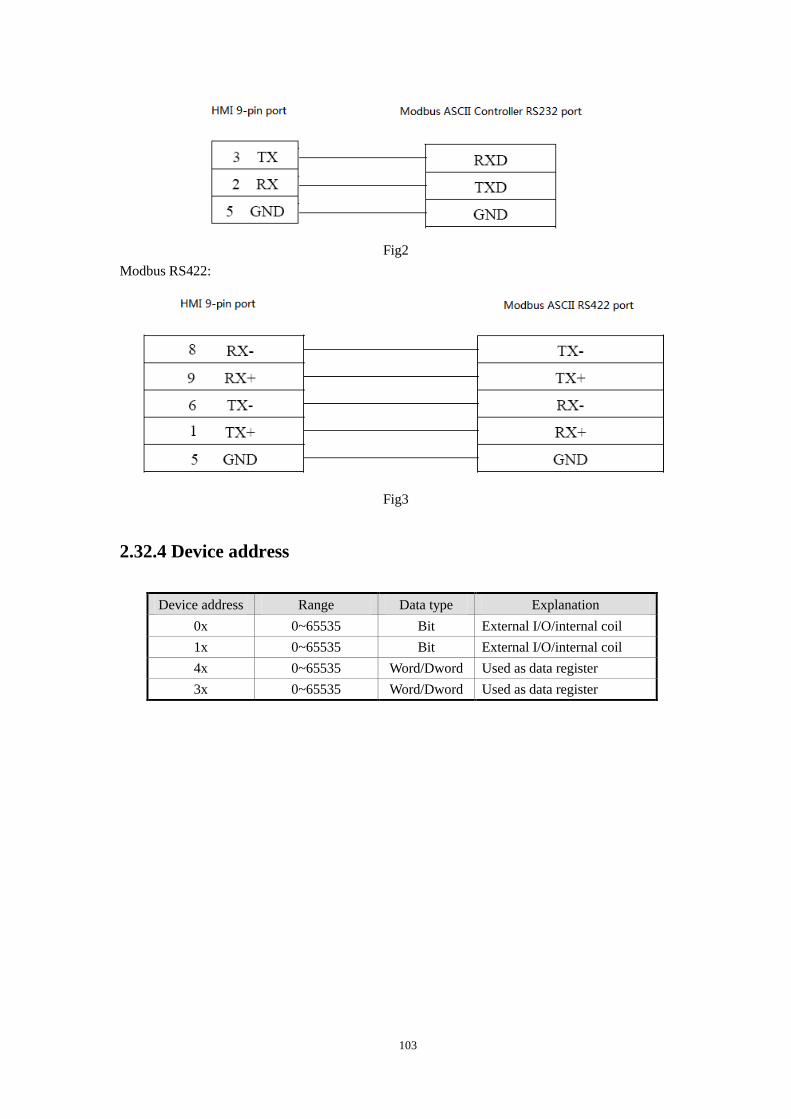
103
Fig2
Modbus RS422:
Fig3
2.32.4 Device address
Device address Range Data type Explanation
0x 0~65535 Bit External I/O/internal coil
1x 0~65535 Bit External I/O/internal coil
4x 0~65535 Word/Dword Used as data register
3x 0~65535 Word/Dword Used as data register
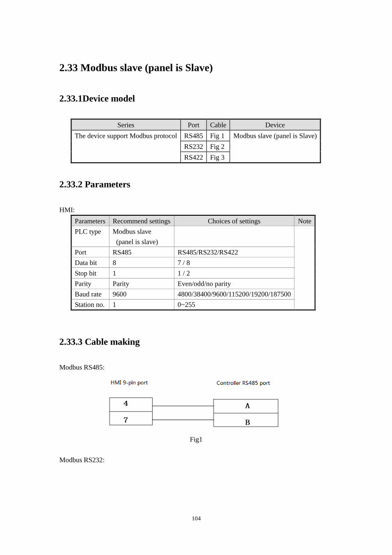
104
2.33 Modbus slave (panel is Slave)
2.33.1Device model
Series Port Cable Device
The device support Modbus protocol RS485 Fig 1 Modbus slave (panel is Slave)
RS232 Fig 2
RS422 Fig 3
2.33.2 Parameters
HMI:
Parameters Recommend settings Choices of settings Note
PLC type Modbus slave
(panel is slave)
Port RS485 RS485/RS232/RS422
Data bit 8 7 / 8
Stop bit 1 1 / 2
Parity Parity Even/odd/no parity
Baud rate 9600 4800/38400/9600/115200/19200/187500
Station no. 1 0~255
2.33.3 Cable making
Modbus RS485:
Fig1
Modbus RS232:
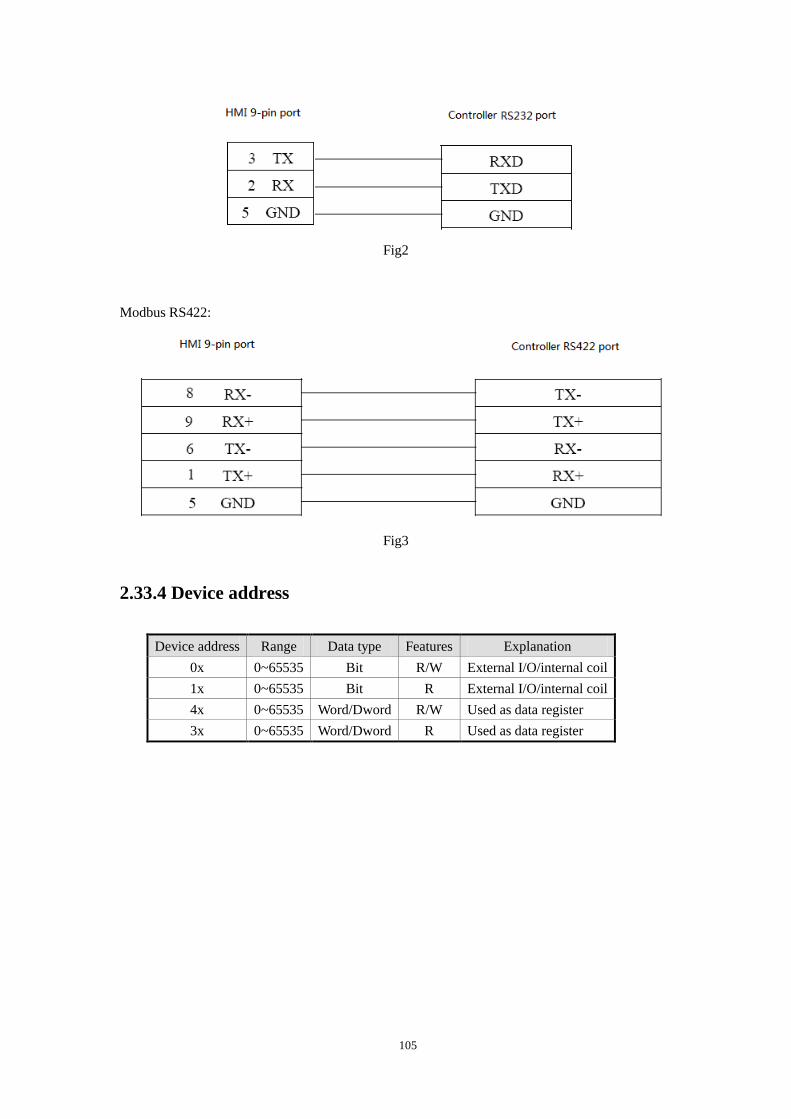
105
Fig2
Modbus RS422:
Fig3
2.33.4 Device address
Device address Range Data type Features Explanation
0x 0~65535 Bit R/W External I/O/internal coil
1x 0~65535 Bit R External I/O/internal coil
4x 0~65535 Word/Dword R/W Used as data register
3x 0~65535 Word/Dword R Used as data register
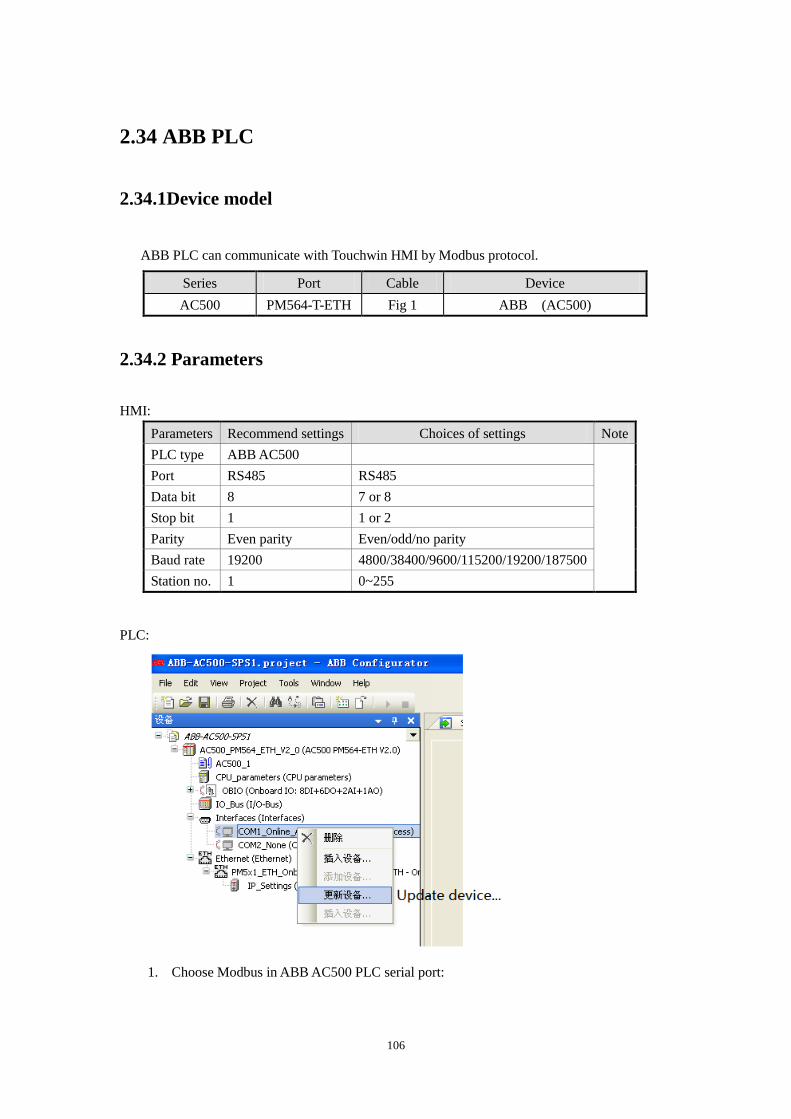
106
2.34 ABB PLC
2.34.1Device model
ABB PLC can communicate with Touchwin HMI by Modbus protocol.
Series Port Cable Device
AC500 PM564-T-ETH Fig 1 ABB (AC500)
2.34.2 Parameters
HMI:
Parameters Recommend settings Choices of settings Note
PLC type ABB AC500
Port RS485 RS485
Data bit 8 7 or 8
Stop bit 1 1 or 2
Parity Even parity Even/odd/no parity
Baud rate 19200 4800/38400/9600/115200/19200/187500
Station no. 1 0~255
PLC:
1. Choose Modbus in ABB AC500 PLC serial port:
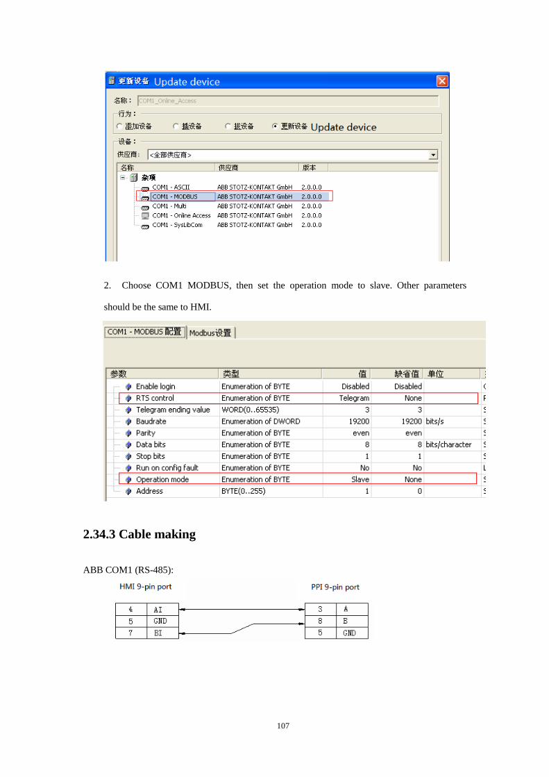
107
2. Choose COM1 MODBUS, then set the operation mode to slave. Other parameters
should be the same to HMI.
2.34.3 Cable making
ABB COM1 (RS-485):
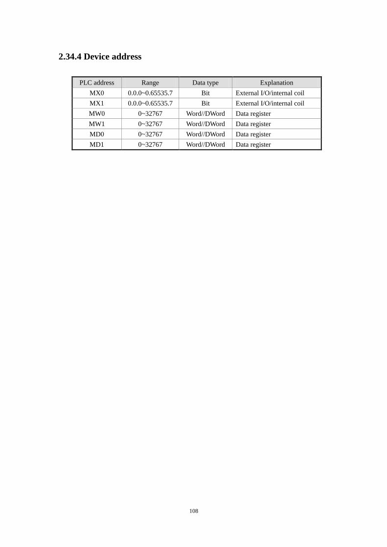
108
2.34.4 Device address
PLC address Range Data type Explanation
MX0 0.0.0~0.65535.7 Bit External I/O/internal coil
MX1 0.0.0~0.65535.7 Bit External I/O/internal coil
MW0 0~32767 Word//DWord Data register
MW1 0~32767 Word//DWord Data register
MD0 0~32767 Word//DWord Data register
MD1 0~32767 Word//DWord Data register
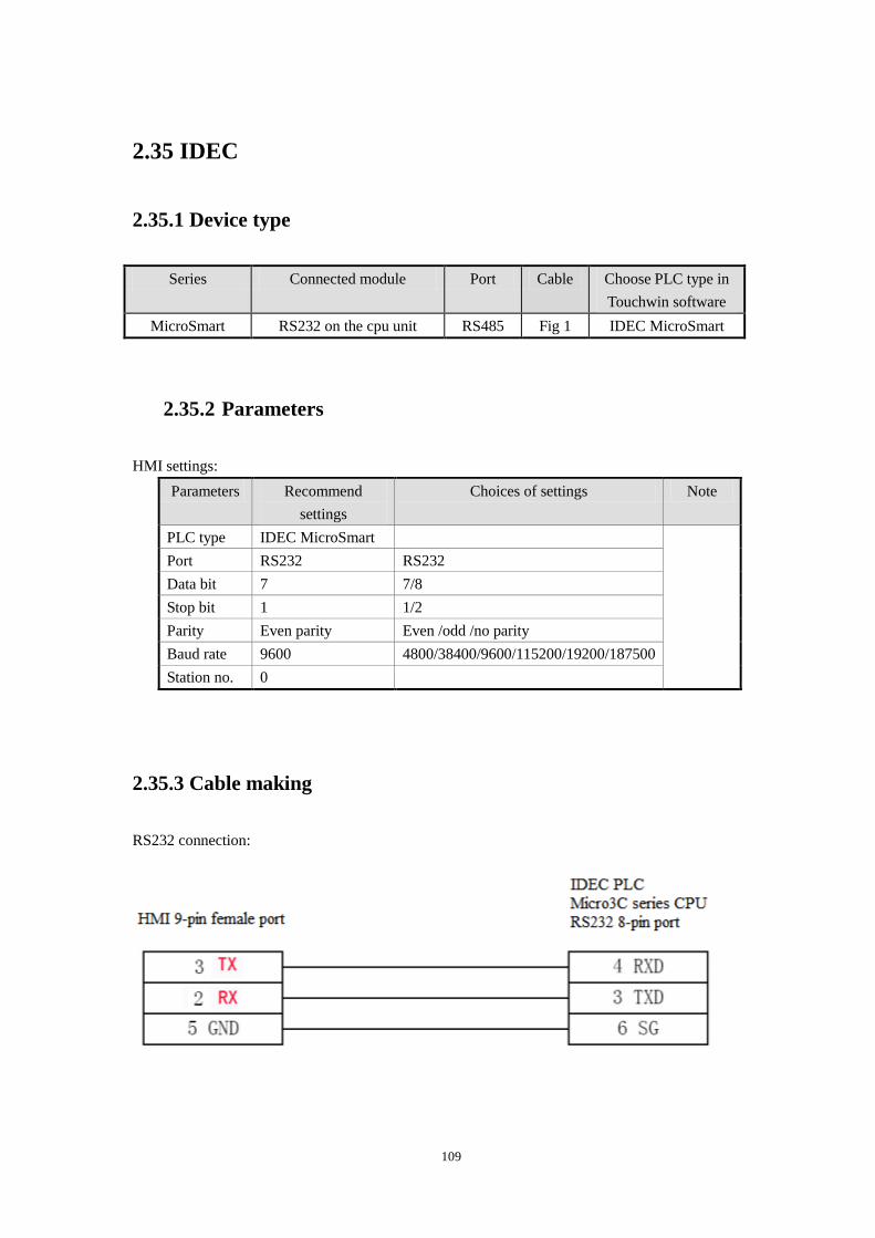
109
2.35 IDEC
2.35.1 Device type
Series Connected module Port Cable Choose PLC type in
Touchwin software
MicroSmart RS232 on the cpu unit RS485 Fig 1 IDEC MicroSmart
2.35.2 Parameters
HMI settings:
Parameters Recommend
settings
Choices of settings Note
PLC type IDEC MicroSmart
Port RS232 RS232
Data bit 7 7/8
Stop bit 1 1/2
Parity Even parity Even /odd /no parity
Baud rate 9600 4800/38400/9600/115200/19200/187500
Station no. 0
2.35.3 Cable making
RS232 connection:
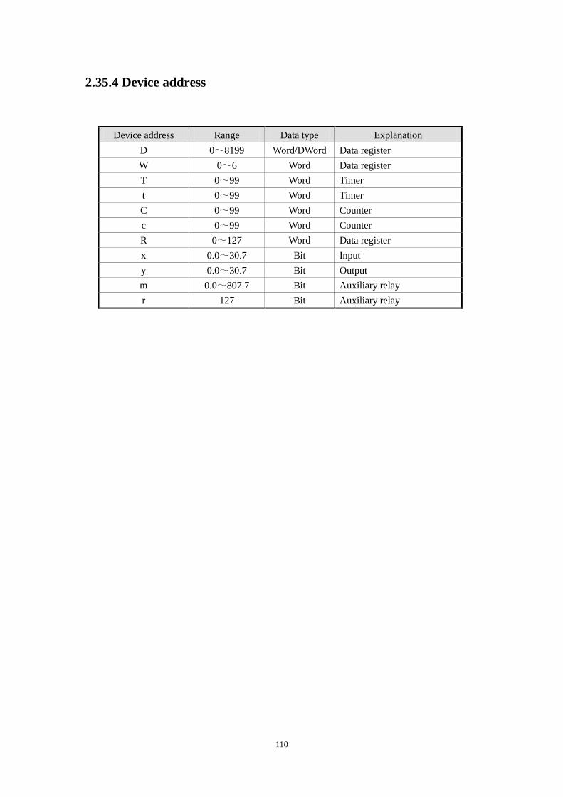
110
2.35.4 Device address
Device address Range Data type Explanation
D 0~8199 Word/DWord Data register
W 0~6 Word Data register
T 0~99 Word Timer
t 0~99 Word Timer
C 0~99 Word Counter
c 0~99 Word Counter
R 0~127 Word Data register
x 0.0~30.7 Bit Input
y 0.0~30.7 Bit Output
m 0.0~807.7 Bit Auxiliary relay
r 127 Bit Auxiliary relay
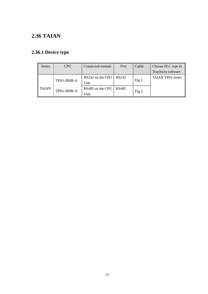
111
2.36 TAIAN
2.36.1 Device type
Series CPU Connected module Port Cable Choose PLC type in
Touchwin software
TAIAN
TP03-20HR-A
TP03-30HR-A
RS232 on the CPU
Unit
RS232 Fig 1
TAIAN TP03 series
RS485 on the CPU
Unit
RS485 Fig 2
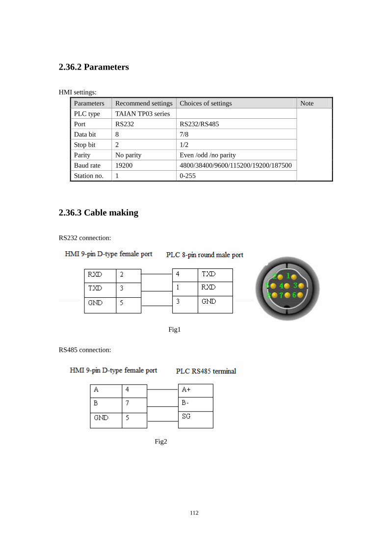
112
2.36.2 Parameters
HMI settings:
Parameters Recommend settings Choices of settings Note
PLC type TAIAN TP03 series
Port RS232 RS232/RS485
Data bit 8 7/8
Stop bit 2 1/2
Parity No parity Even /odd /no parity
Baud rate 19200 4800/38400/9600/115200/19200/187500
Station no. 1 0-255
2.36.3 Cable making
RS232 connection:
Fig1
RS485 connection:
Fig2
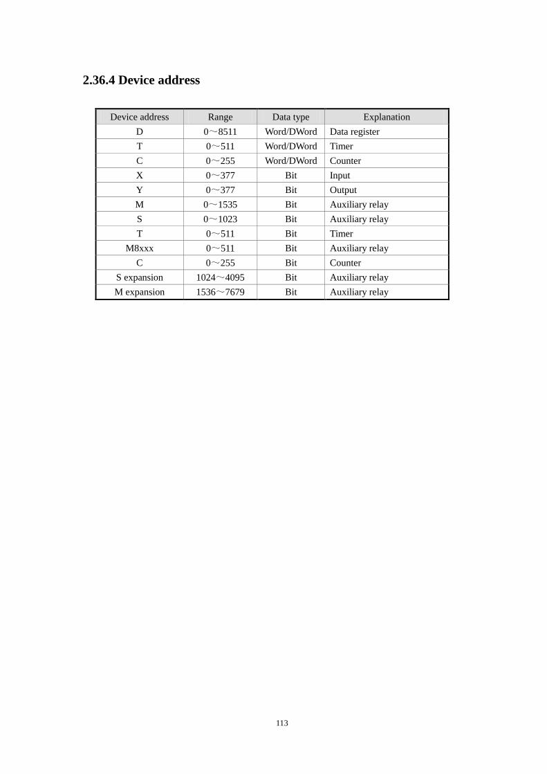
113
2.36.4 Device address
Device address Range Data type Explanation
D 0~8511 Word/DWord Data register
T 0~511 Word/DWord Timer
C 0~255 Word/DWord Counter
X 0~377 Bit Input
Y 0~377 Bit Output
M 0~1535 Bit Auxiliary relay
S 0~1023 Bit Auxiliary relay
T 0~511 Bit Timer
M8xxx 0~511 Bit Auxiliary relay
C 0~255 Bit Counter
S expansion 1024~4095 Bit Auxiliary relay
M expansion 1536~7679 Bit Auxiliary relay
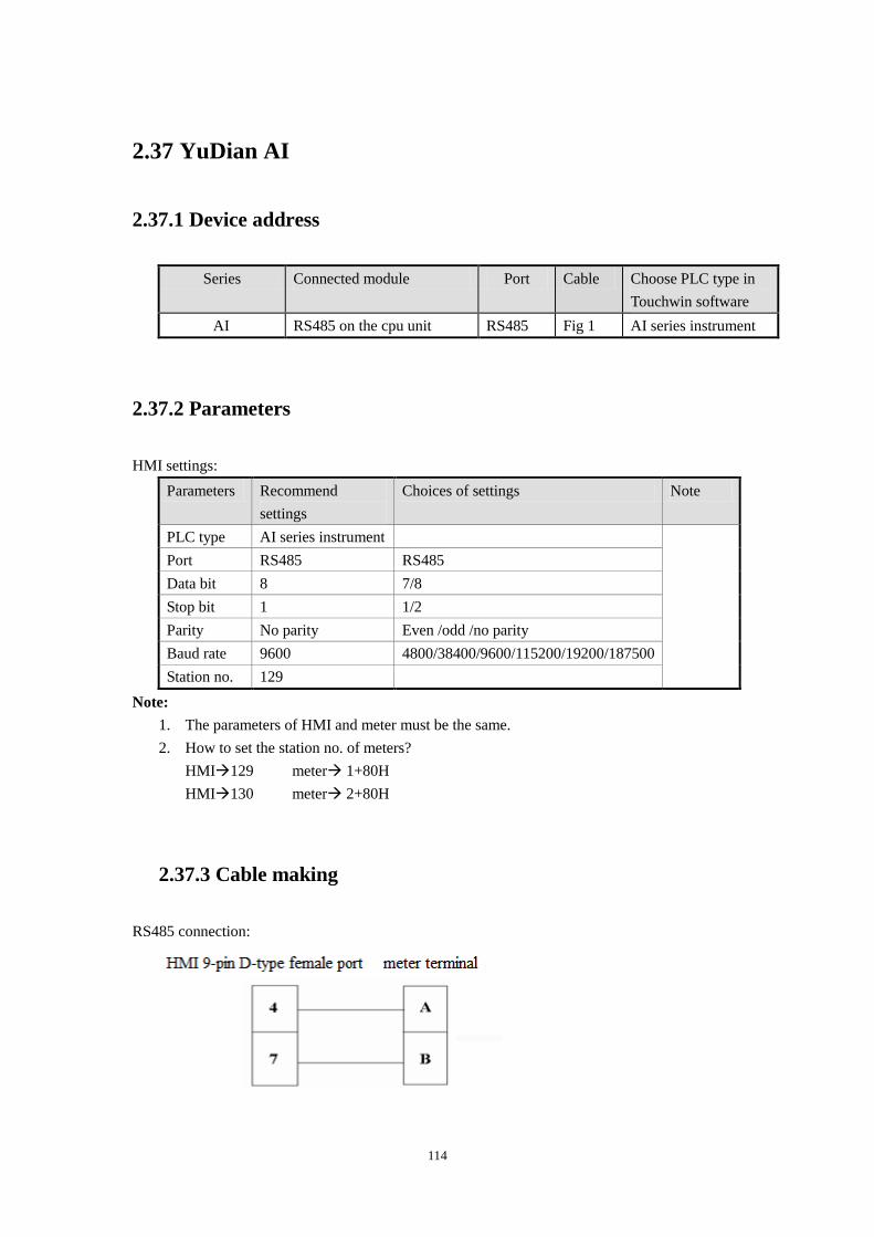
114
2.37 YuDian AI
2.37.1 Device address
Series Connected module Port Cable Choose PLC type in
Touchwin software
AI RS485 on the cpu unit RS485 Fig 1 AI series instrument
2.37.2 Parameters
HMI settings:
Parameters Recommend
settings
Choices of settings Note
PLC type AI series instrument
Port RS485 RS485
Data bit 8 7/8
Stop bit 1 1/2
Parity No parity Even /odd /no parity
Baud rate 9600 4800/38400/9600/115200/19200/187500
Station no. 129
Note:
1. The parameters of HMI and meter must be the same.
2. How to set the station no. of meters?
HMI129 meter 1+80H
HMI130 meter 2+80H
2.37.3 Cable making
RS485 connection:
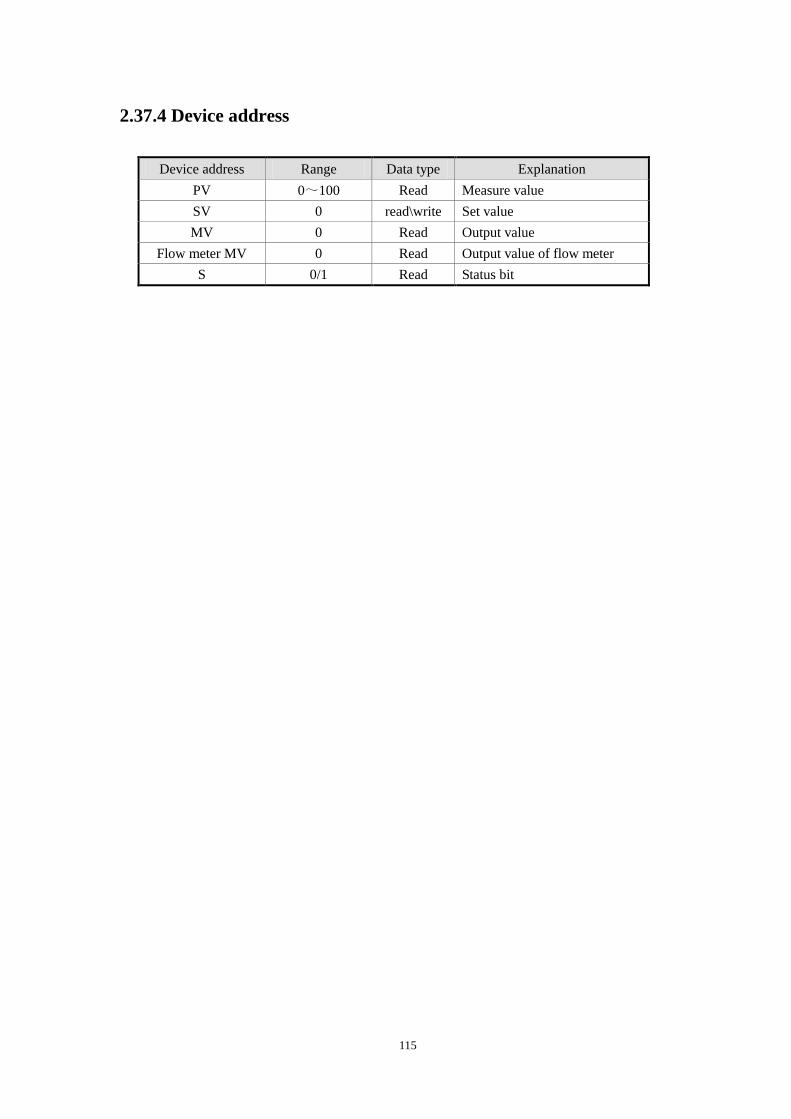
115
2.37.4 Device address
Device address Range Data type Explanation
PV 0~100 Read Measure value
SV 0 read\write Set value
MV 0 Read Output value
Flow meter MV 0 Read Output value of flow meter
S 0/1 Read Status bit
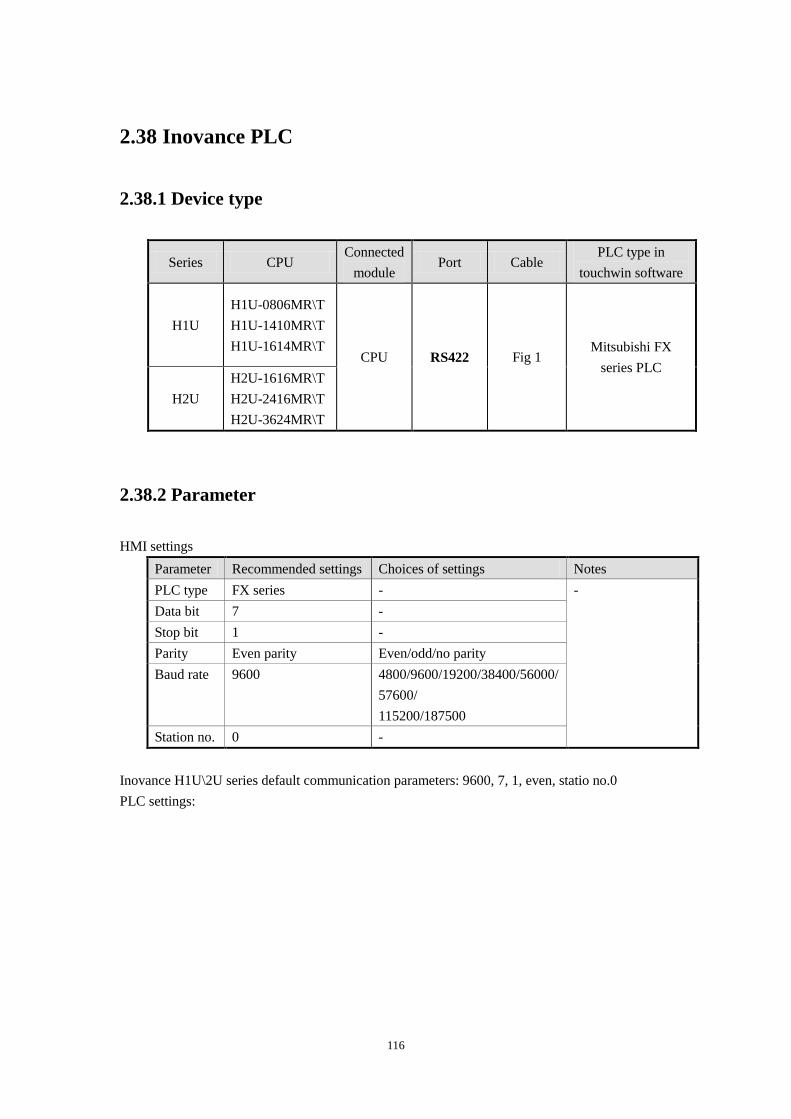
116
2.38 Inovance PLC
2.38.1 Device type
Series CPU Connected
module Port Cable
PLC type in
touchwin software
H1U
H1U-0806MR\T
H1U-1410MR\T
H1U-1614MR\T CPU RS422 Fig 1
Mitsubishi FX
series PLC
H2U
H2U-1616MR\T
H2U-2416MR\T
H2U-3624MR\T
2.38.2 Parameter
HMI settings
Parameter Recommended settings Choices of settings Notes
PLC type FX series - -
Data bit 7 -
Stop bit 1 -
Parity Even parity Even/odd/no parity
Baud rate 9600 4800/9600/19200/38400/56000/
57600/
115200/187500
Station no. 0 -
Inovance H1U\2U series default communication parameters: 9600, 7, 1, even, statio no.0
PLC settings:
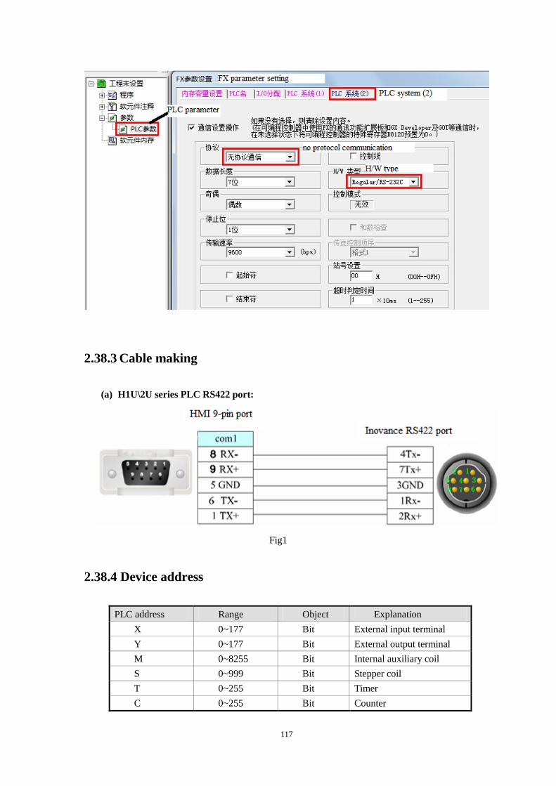
117
2.38.3 Cable making
(a) H1U\2U series PLC RS422 port:
Fig1
2.38.4 Device address
PLC address Range Object Explanation
X 0~177 Bit External input terminal
Y 0~177 Bit External output terminal
M 0~8255 Bit Internal auxiliary coil
S 0~999 Bit Stepper coil
T 0~255 Bit Timer
C 0~255 Bit Counter
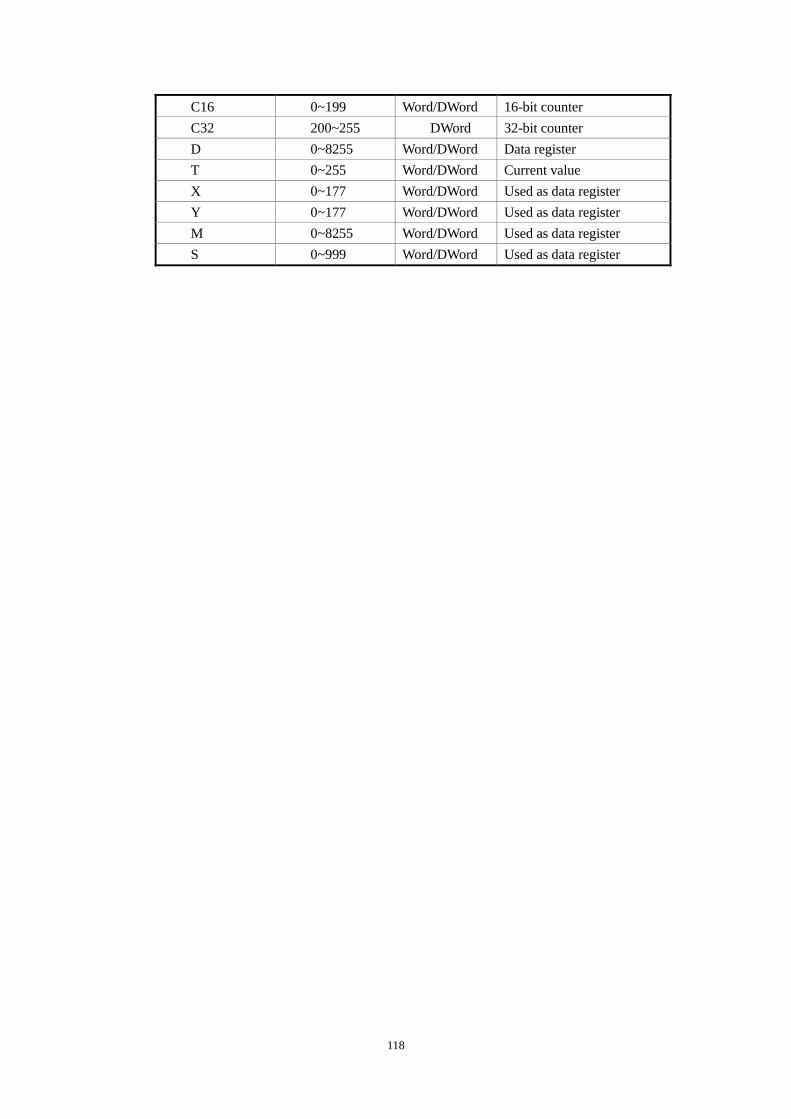
118
C16 0~199 Word/DWord 16-bit counter
C32 200~255 DWord 32-bit counter
D 0~8255 Word/DWord Data register
T 0~255 Word/DWord Current value
X 0~177 Word/DWord Used as data register
Y 0~177 Word/DWord Used as data register
M 0~8255 Word/DWord Used as data register
S 0~999 Word/DWord Used as data register
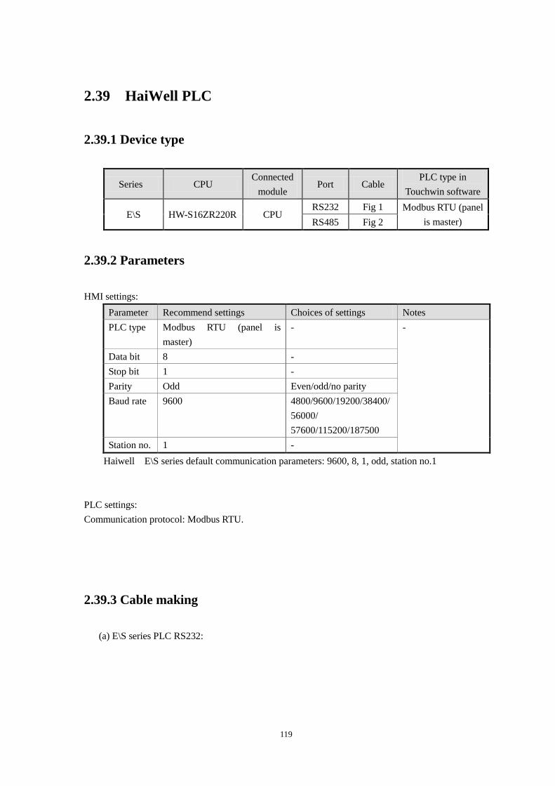
119
2.39 HaiWell PLC
2.39.1 Device type
Series CPU Connected
module Port Cable
PLC type in
Touchwin software
E\S HW-S16ZR220R CPU RS232 Fig 1 Modbus RTU (panel
is master) RS485 Fig 2
2.39.2 Parameters
HMI settings:
Parameter Recommend settings Choices of settings Notes
PLC type Modbus RTU (panel is
master)
- -
Data bit 8 -
Stop bit 1 -
Parity Odd Even/odd/no parity
Baud rate 9600 4800/9600/19200/38400/
56000/
57600/115200/187500
Station no. 1 -
Haiwell E\S series default communication parameters: 9600, 8, 1, odd, station no.1
PLC settings:
Communication protocol: Modbus RTU.
2.39.3 Cable making
(a) E\S series PLC RS232:
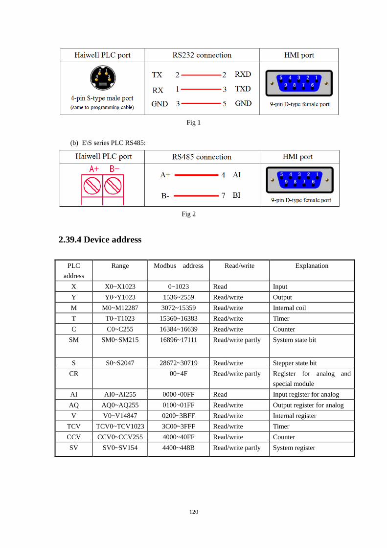
120
Fig 1
(b) E\S series PLC RS485:
Fig 2
2.39.4 Device address
PLC
address
Range Modbus address Read/write Explanation
X X0~X1023 0~1023 Read Input
Y Y0~Y1023 1536~2559 Read/write Output
M M0~M12287 3072~15359 Read/write Internal coil
T T0~T1023 15360~16383 Read/write Timer
C C0~C255 16384~16639 Read/write Counter
SM SM0~SM215 16896~17111 Read/write partly System state bit
S S0~S2047 28672~30719 Read/write Stepper state bit
CR 00~4F Read/write partly Register for analog and
special module
AI AI0~AI255 0000~00FF Read Input register for analog
AQ AQ0~AQ255 0100~01FF Read/write Output register for analog
V V0~V14847 0200~3BFF Read/write Internal register
TCV TCV0~TCV1023 3C00~3FFF Read/write Timer
CCV CCV0~CCV255 4000~40FF Read/write Counter
SV SV0~SV154 4400~448B Read/write partly System register
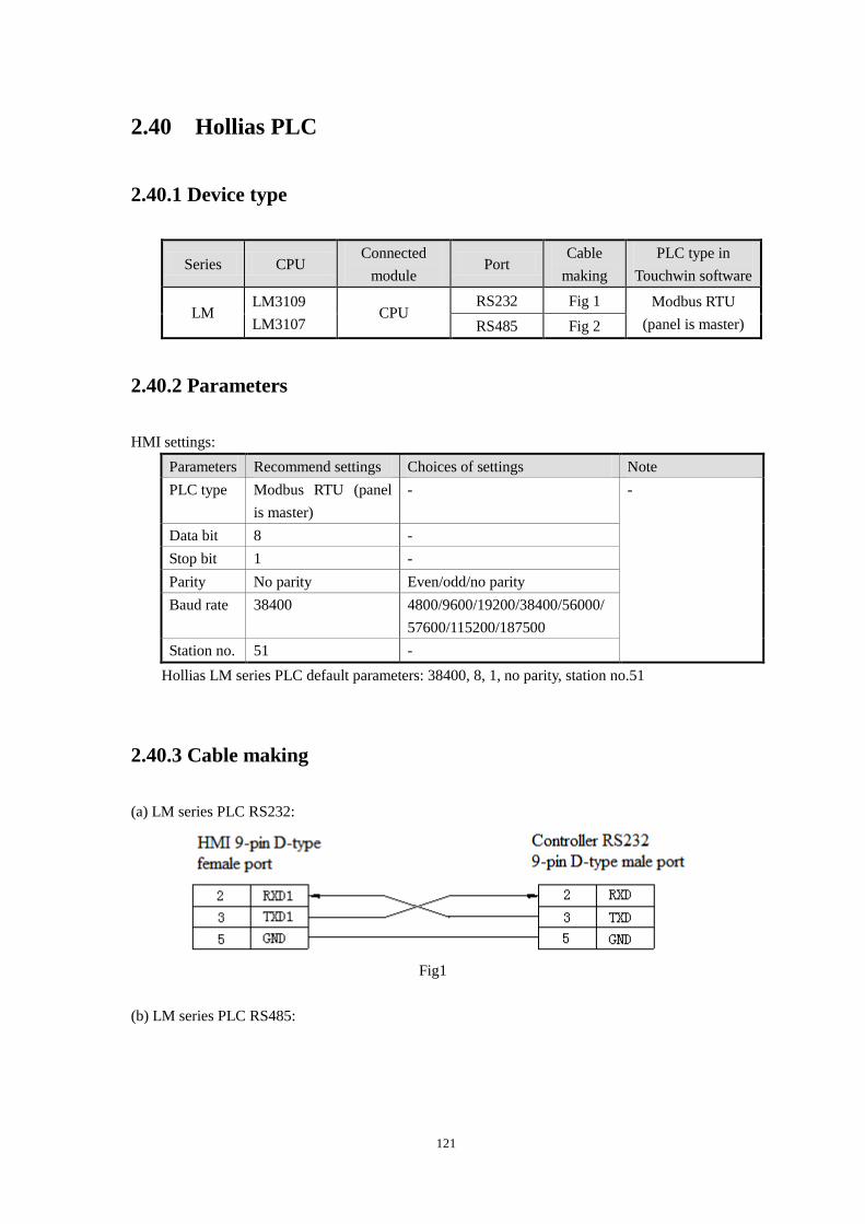
121
2.40 Hollias PLC
2.40.1 Device type
Series CPU Connected
module Port
Cable
making
PLC type in
Touchwin software
LM LM3109
LM3107 CPU
RS232 Fig 1 Modbus RTU
(panel is master) RS485 Fig 2
2.40.2 Parameters
HMI settings:
Parameters Recommend settings Choices of settings Note
PLC type Modbus RTU (panel
is master)
- -
Data bit 8 -
Stop bit 1 -
Parity No parity Even/odd/no parity
Baud rate 38400 4800/9600/19200/38400/56000/
57600/115200/187500
Station no. 51 -
Hollias LM series PLC default parameters: 38400, 8, 1, no parity, station no.51
2.40.3 Cable making
(a) LM series PLC RS232:
Fig1
(b) LM series PLC RS485:
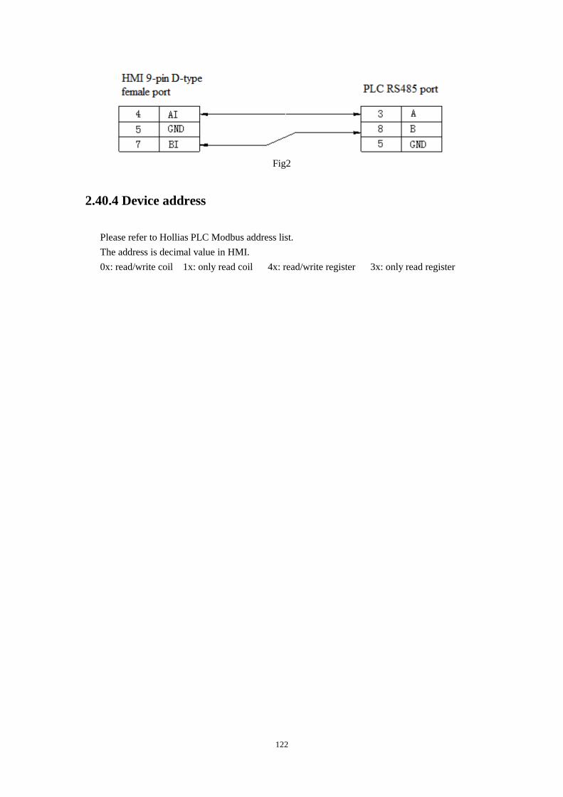
122
Fig2
2.40.4 Device address
Please refer to Hollias PLC Modbus address list.
The address is decimal value in HMI.
0x: read/write coil 1x: only read coil 4x: read/write register 3x: only read register
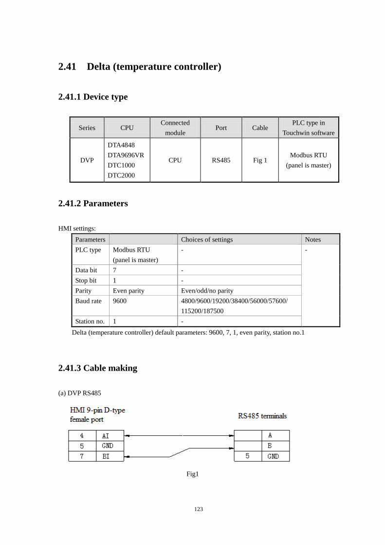
123
2.41 Delta (temperature controller)
2.41.1 Device type
Series CPU Connected
module Port Cable
PLC type in
Touchwin software
DVP
DTA4848
DTA9696VR
DTC1000
DTC2000
CPU RS485 Fig 1 Modbus RTU
(panel is master)
2.41.2 Parameters
HMI settings:
Parameters Choices of settings Notes
PLC type Modbus RTU
(panel is master)
- -
Data bit 7 -
Stop bit 1 -
Parity Even parity Even/odd/no parity
Baud rate 9600 4800/9600/19200/38400/56000/57600/
115200/187500
Station no. 1 -
Delta (temperature controller) default parameters: 9600, 7, 1, even parity, station no.1
2.41.3 Cable making
(a) DVP RS485
Fig1

124
2.41.4 Device address
Please refer to Delta temperature controller Modbus address list.
The address is decimal in HMI.
0x: read/write coil 1x: only read coil 4x: read/write register 3x: only read register
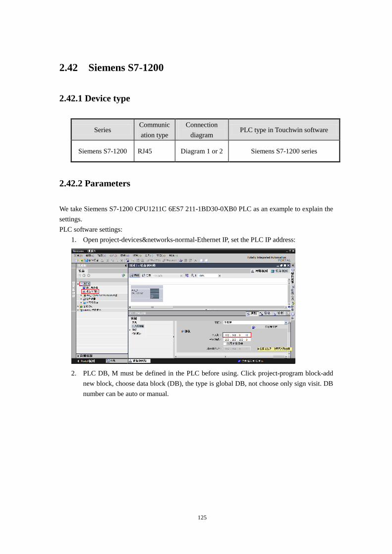
125
2.42 Siemens S7-1200
2.42.1 Device type
Series Communic
ation type
Connection
diagram PLC type in Touchwin software
Siemens S7-1200 RJ45 Diagram 1 or 2 Siemens S7-1200 series
2.42.2 Parameters
We take Siemens S7-1200 CPU1211C 6ES7 211-1BD30-0XB0 PLC as an example to explain the
settings.
PLC software settings:
1. Open project-devices&networks-normal-Ethernet IP, set the PLC IP address:
2. PLC DB, M must be defined in the PLC before using. Click project-program block-add
new block, choose data block (DB), the type is global DB, not choose only sign visit. DB
number can be auto or manual.
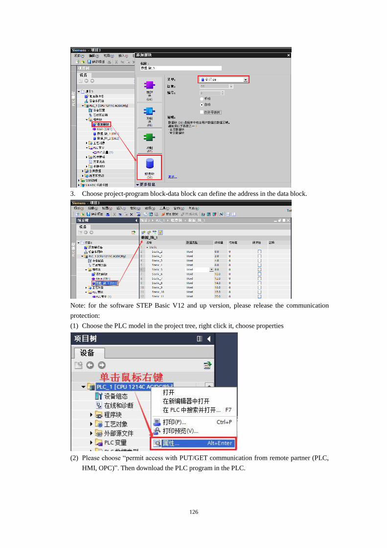
126
3. Choose project-program block-data block can define the address in the data block.
Note: for the software STEP Basic V12 and up version, please release the communication
protection:
(1) Choose the PLC model in the project tree, right click it, choose properties
(2) Please choose “permit access with PUT/GET communication from remote partner (PLC,
HMI, OPC)”. Then download the PLC program in the PLC.
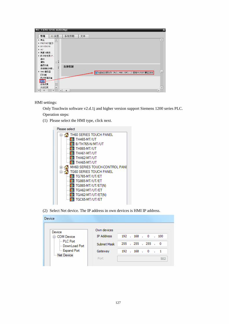
127
HMI settings:
Only Touchwin software v2.d.1j and higher version support Siemens 1200 series PLC.
Operation steps:
(1) Please select the HMI type, click next.
(2) Select Net device. The IP address in own devices is HMI IP address.
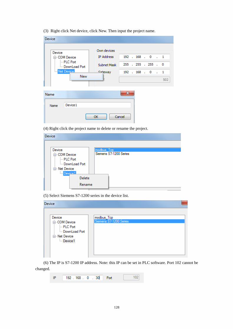
128
(3) Right click Net device, click New. Then input the project name.
(4) Right click the project name to delete or rename the project.
(5) Select Siemens S7-1200 series in the device list.
(6) The IP is S7-1200 IP address. Note: this IP can be set in PLC software. Port 102 cannot be
changed.
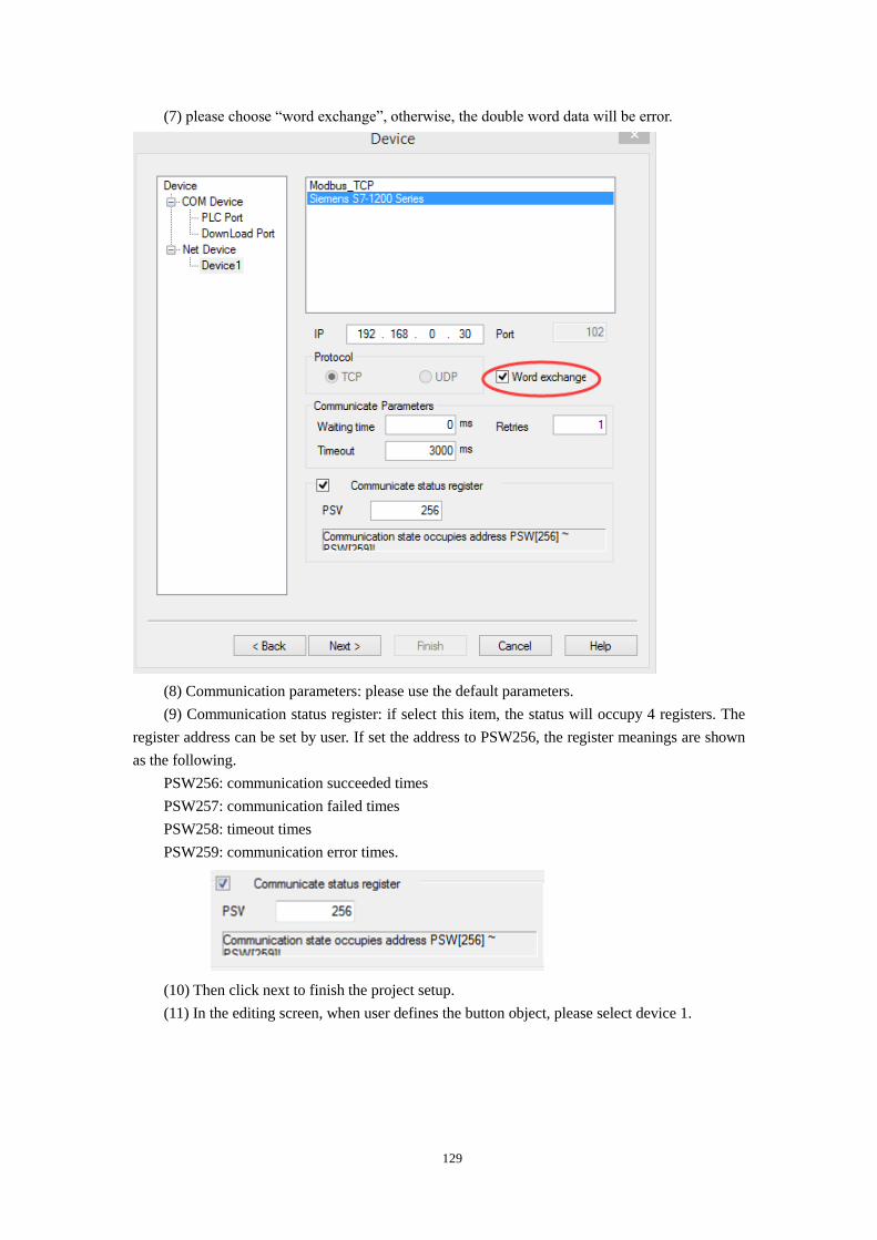
129
(7) please choose “word exchange”, otherwise, the double word data will be error.
(8) Communication parameters: please use the default parameters.
(9) Communication status register: if select this item, the status will occupy 4 registers. The
register address can be set by user. If set the address to PSW256, the register meanings are shown
as the following.
PSW256: communication succeeded times
PSW257: communication failed times
PSW258: timeout times
PSW259: communication error times.
(10) Then click next to finish the project setup.
(11) In the editing screen, when user defines the button object, please select device 1.
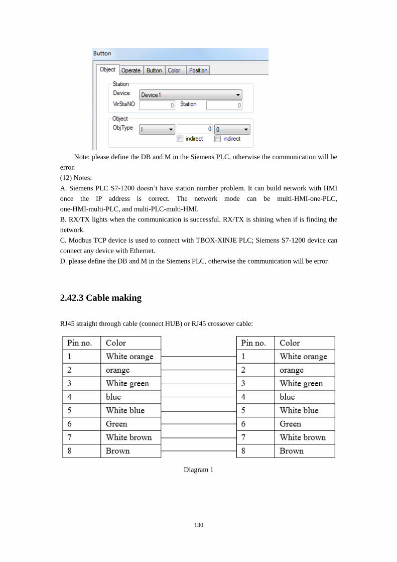
130
Note: please define the DB and M in the Siemens PLC, otherwise the communication will be
error.
(12) Notes:
A. Siemens PLC S7-1200 doesn’t have station number problem. It can build network with HMI
once the IP address is correct. The network mode can be multi-HMI-one-PLC,
one-HMI-multi-PLC, and multi-PLC-multi-HMI.
B. RX/TX lights when the communication is successful. RX/TX is shining when if is finding the
network.
C. Modbus TCP device is used to connect with TBOX-XINJE PLC; Siemens S7-1200 device can
connect any device with Ethernet.
D. please define the DB and M in the Siemens PLC, otherwise the communication will be error.
2.42.3 Cable making
RJ45 straight through cable (connect HUB) or RJ45 crossover cable:
Diagram 1
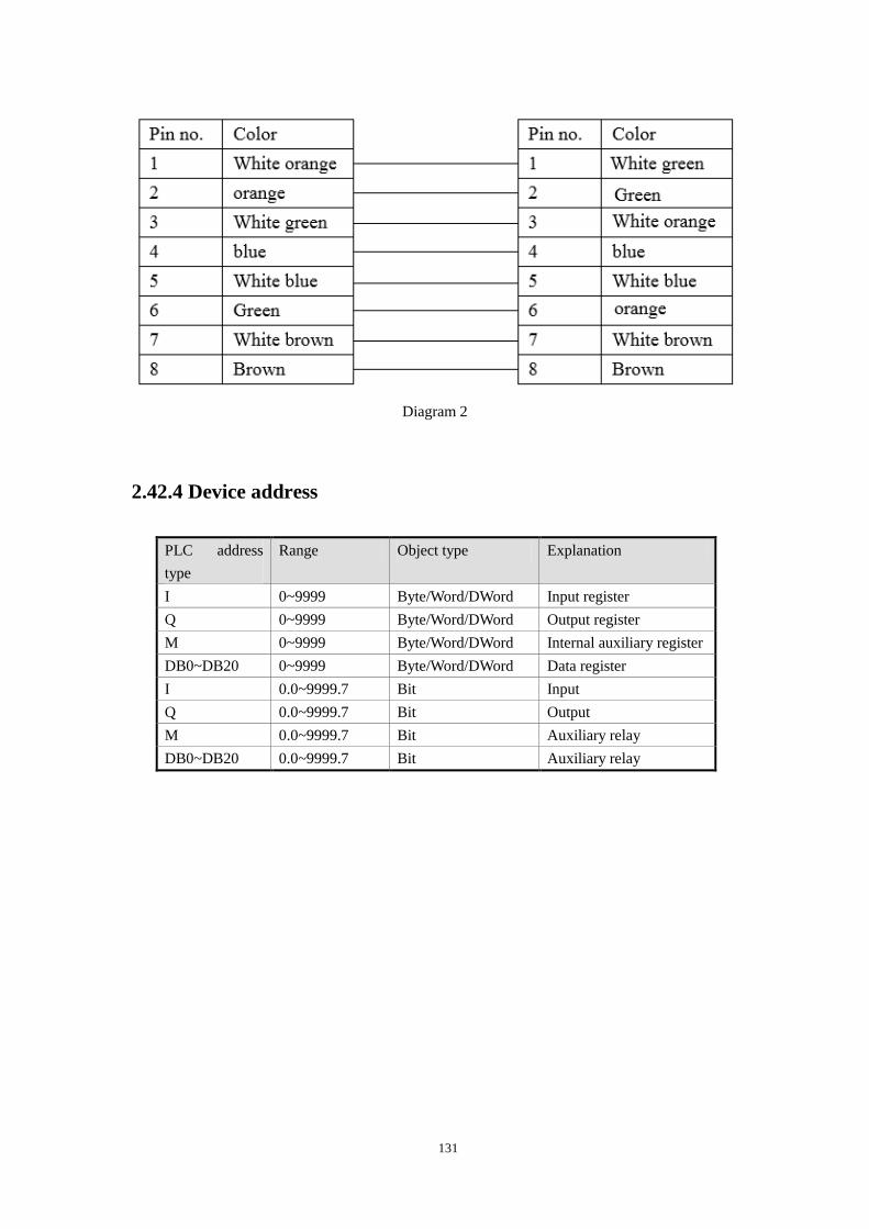
131
Diagram 2
2.42.4 Device address
PLC address
type
Range Object type Explanation
I 0~9999 Byte/Word/DWord Input register
Q 0~9999 Byte/Word/DWord Output register
M 0~9999 Byte/Word/DWord Internal auxiliary register
DB0~DB20 0~9999 Byte/Word/DWord Data register
I 0.0~9999.7 Bit Input
Q 0.0~9999.7 Bit Output
M 0.0~9999.7 Bit Auxiliary relay
DB0~DB20 0.0~9999.7 Bit Auxiliary relay
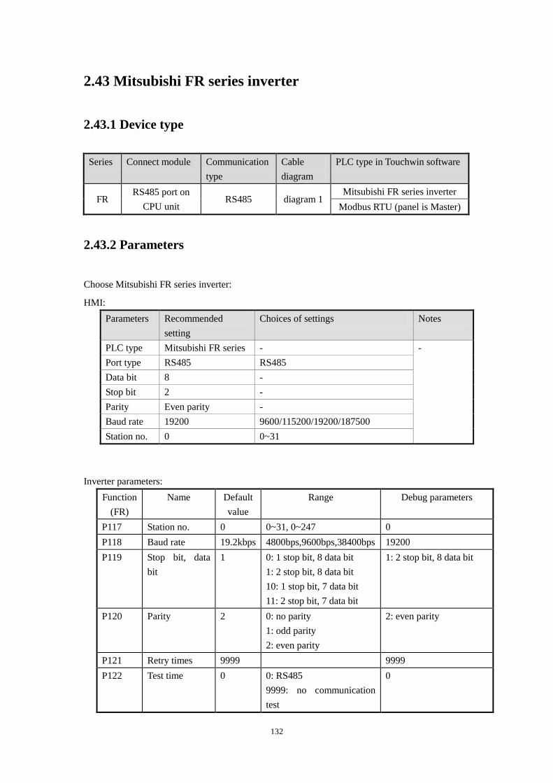
132
2.43 Mitsubishi FR series inverter
2.43.1 Device type
Series Connect module Communication
type
Cable
diagram
PLC type in Touchwin software
FR RS485 port on
CPU unit RS485 diagram 1
Mitsubishi FR series inverter
Modbus RTU (panel is Master)
2.43.2 Parameters
Choose Mitsubishi FR series inverter:
HMI:
Parameters Recommended
setting
Choices of settings Notes
PLC type Mitsubishi FR series - -
Port type RS485 RS485
Data bit 8 -
Stop bit 2 -
Parity Even parity -
Baud rate 19200 9600/115200/19200/187500
Station no. 0 0~31
Inverter parameters:
Function
(FR)
Name Default
value
Range Debug parameters
P117 Station no. 0 0~31, 0~247 0
P118 Baud rate 19.2kbps 4800bps,9600bps,38400bps 19200
P119 Stop bit, data
bit
1 0: 1 stop bit, 8 data bit
1: 2 stop bit, 8 data bit
10: 1 stop bit, 7 data bit
11: 2 stop bit, 7 data bit
1: 2 stop bit, 8 data bit
P120 Parity 2 0: no parity
1: odd parity
2: even parity
2: even parity
P121 Retry times 9999 9999
P122 Test time 0 0: RS485
9999: no communication
test
0
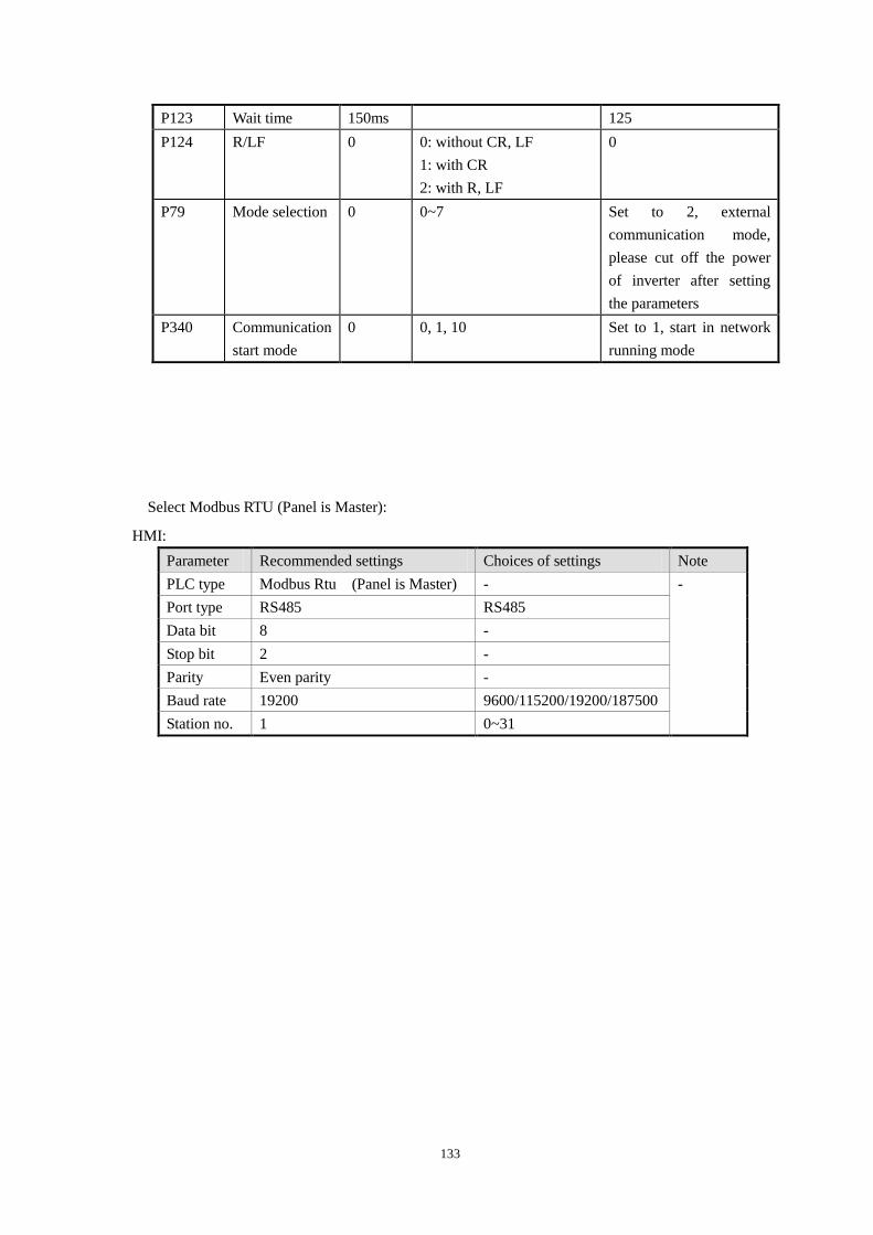
133
P123 Wait time 150ms 125
P124 R/LF
0 0: without CR, LF
1: with CR
2: with R, LF
0
P79 Mode selection 0 0~7 Set to 2, external
communication mode,
please cut off the power
of inverter after setting
the parameters
P340 Communication
start mode
0 0, 1, 10 Set to 1, start in network
running mode
Select Modbus RTU (Panel is Master):
HMI:
Parameter Recommended settings Choices of settings Note
PLC type Modbus Rtu (Panel is Master) - -
Port type RS485 RS485
Data bit 8 -
Stop bit 2 -
Parity Even parity -
Baud rate 19200 9600/115200/19200/187500
Station no. 1 0~31
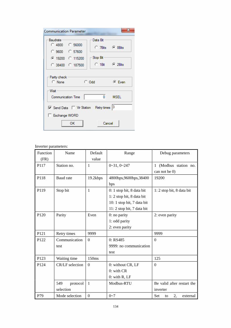
134
Inverter parameters:
Function
(FR)
Name Default
value
Range Debug parameters
P117 Station no. 1 0~31, 0~247 1 (Modbus station no.
can not be 0)
P118 Baud rate 19.2kbps 4800bps,9600bps,38400
bps
19200
P119 Stop bit 1 0: 1 stop bit, 8 data bit
1: 2 stop bit, 8 data bit
10: 1 stop bit, 7 data bit
11: 2 stop bit, 7 data bit
1: 2 stop bit, 8 data bit
P120 Parity Even 0: no parity
1: odd parity
2: even parity
2: even parity
P121 Retry times 9999 9999
P122 Communication
test
0 0: RS485
9999: no communication
test
0
P123 Waiting time 150ms 125
P124 CR/LF selection 0 0: without CR, LF
0: with CR
0: with R, LF
0
549 protocol
selection
1 Modbus-RTU Be valid after restart the
inverter
P79 Mode selection 0 0~7 Set to 2, external
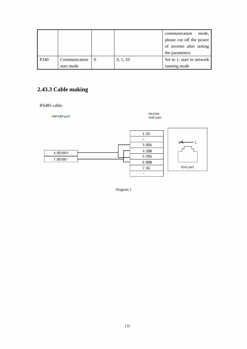
135
communication mode,
please cut off the power
of inverter after setting
the parameters
P340 Communication
start mode
0 0, 1, 10 Set to 1, start in network
running mode
2.43.3 Cable making
RS485 cable:
Diagram 1
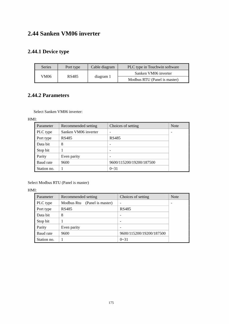
175
2.44 Sanken VM06 inverter
2.44.1 Device type
Series Port type Cable diagram PLC type in Touchwin software
VM06 RS485 diagram 1 Sanken VM06 inverter
Modbus RTU (Panel is master)
2.44.2 Parameters
Select Sanken VM06 inverter:
HMI:
Parameter Recommended setting Choices of setting Note
PLC type Sanken VM06 inverter - -
Port type RS485 RS485
Data bit 8 -
Stop bit 1 -
Parity Even parity -
Baud rate 9600 9600/115200/19200/187500
Station no. 1 0~31
Select Modbus RTU (Panel is master)
HMI:
Parameter Recommended setting Choices of setting Note
PLC type Modbus Rtu (Panel is master) - -
Port type RS485 RS485
Data bit 8 -
Stop bit 1 -
Parity Even parity -
Baud rate 9600 9600/115200/19200/187500
Station no. 1 0~31
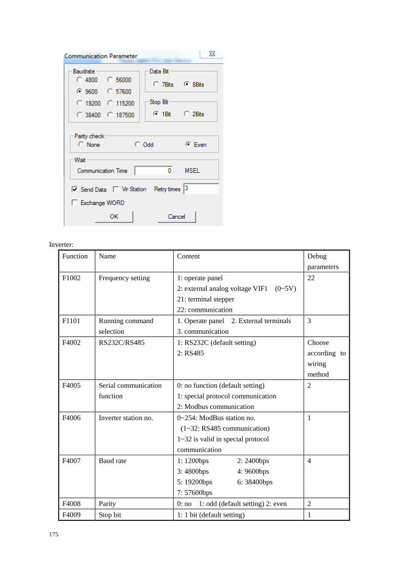
175
Inverter:
Function Name Content Debug
parameters
F1002 Frequency setting 1: operate panel
2: external analog voltage VIF1 (0~5V)
21: terminal stepper
22: communication
22
F1101 Running command
selection
1. Operate panel 2. External terminals
3. communication
3
F4002 RS232C/RS485
1: RS232C (default setting)
2: RS485
Choose
according to
wiring
method
F4005 Serial communication
function
0: no function (default setting)
1: special protocol communication
2: Modbus communication
2
F4006 Inverter station no.
0~254: ModBus station no.
(1~32: RS485 communication)
1~32 is valid in special protocol
communication
1
F4007 Baud rate 1: 1200bps 2: 2400bps
3: 4800bps 4: 9600bps
5: 19200bps 6: 38400bps
7: 57600bps
4
F4008 Parity 0: no 1: odd (default setting) 2: even 2
F4009 Stop bit 1: 1 bit (default setting) 1
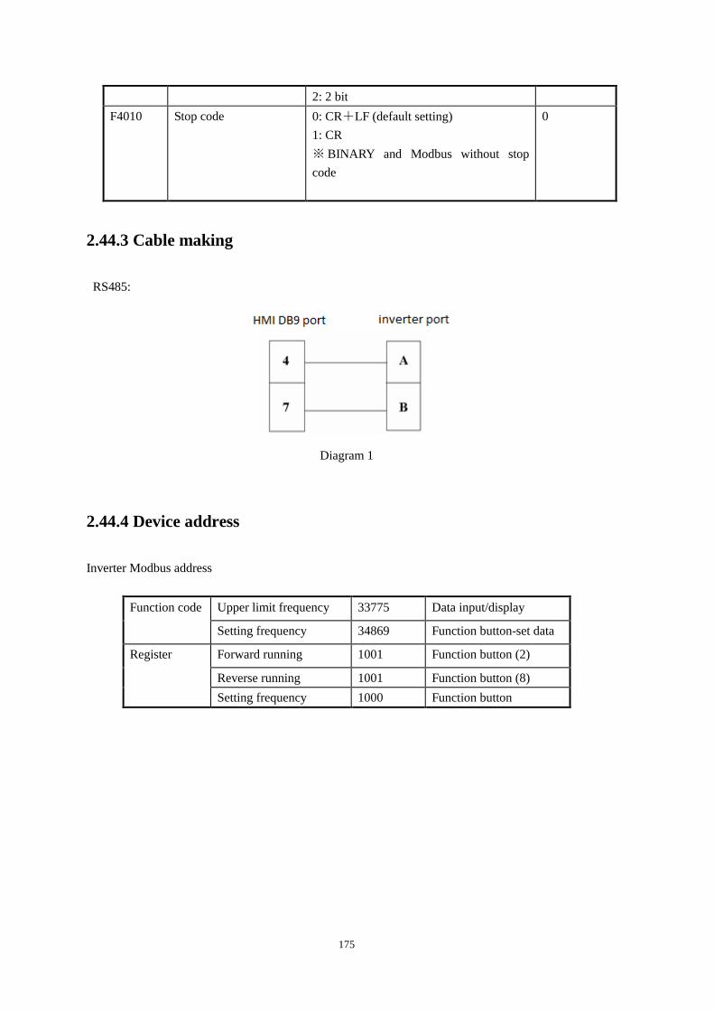
175
2: 2 bit
F4010 Stop code
0: CR+LF (default setting)
1: CR
※ BINARY and Modbus without stop
code
0
2.44.3 Cable making
RS485:
Diagram 1
2.44.4 Device address
Inverter Modbus address
Function code Upper limit frequency 33775 Data input/display
Setting frequency 34869 Function button-set data
Register Forward running 1001 Function button (2)
Reverse running 1001 Function button (8)
Setting frequency 1000 Function button
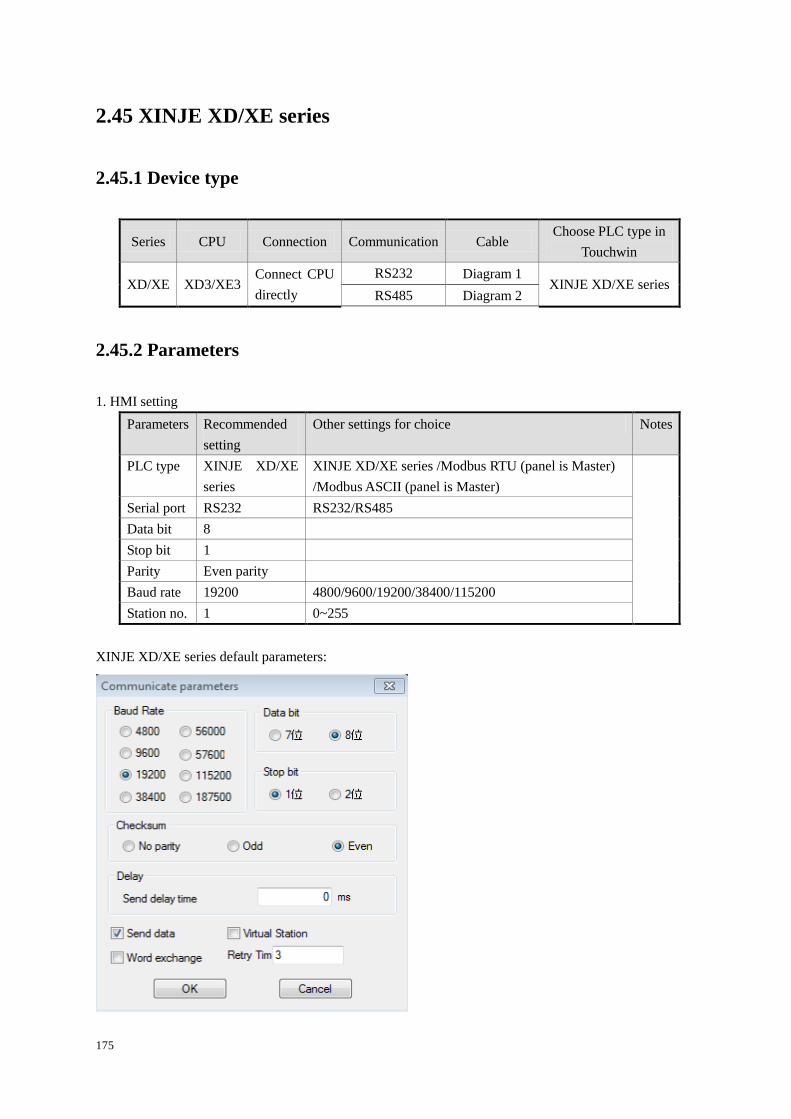
175
2.45 XINJE XD/XE series
2.45.1 Device type
Series CPU Connection Communication Cable Choose PLC type in
Touchwin
XD/XE XD3/XE3 Connect CPU
directly
RS232 Diagram 1 XINJE XD/XE series
RS485 Diagram 2
2.45.2 Parameters
1. HMI setting
Parameters Recommended
setting
Other settings for choice Notes
PLC type XINJE XD/XE
series
XINJE XD/XE series /Modbus RTU (panel is Master)
/Modbus ASCII (panel is Master)
Serial port RS232 RS232/RS485
Data bit 8
Stop bit 1
Parity Even parity
Baud rate 19200 4800/9600/19200/38400/115200
Station no. 1 0~255
XINJE XD/XE series default parameters:
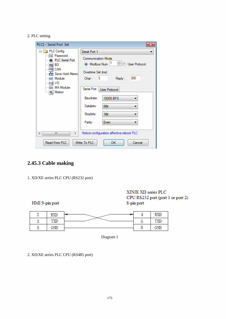
175
2. PLC setting
2.45.3 Cable making
1. XD/XE series PLC CPU (RS232 port)
Diagram 1
2. XD/XE series PLC CPU (RS485 port)
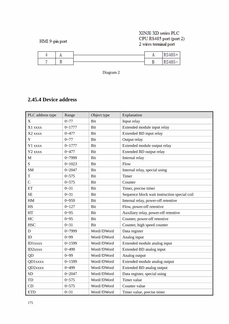
175
Diagram 2
2.45.4 Device address
PLC address type Range Object type Explanation
X 0~77 Bit Input relay
X1 xxxx 0~1777 Bit Extended module input relay
X2 xxxx 0~477 Bit Extended BD input relay
Y 0~77 Bit Output relay
Y1 xxxx 0~1777 Bit Extended module output relay
Y2 xxxx 0~477 Bit Extended BD output relay
M 0~7999 Bit Internal relay
S 0~1023 Bit Flow
SM 0~2047 Bit Internal relay, special using
T 0~575 Bit Timer
C 0~575 Bit Counter
ET 0~31 Bit Timer, precise timer
SE 0~31 Bit Sequence block wait instruction special coil
HM 0~959 Bit Internal relay, power-off retentive
HS 0~127 Bit Flow, power-off retentive
HT 0~95 Bit Auxiliary relay, power-off retentive
HC 0~95 Bit Counter, power-off retentive
HSC 0~31 Bit Counter, high speed counter
D 0~7999 Word//DWord Data register
ID 0~99 Word//DWord Analog input
ID1xxxx 0~1599 Word//DWord Extended module analog input
ID2xxxx 0~499 Word//DWord Extended BD analog input
QD 0~99 Word//DWord Analog output
QD1xxxx 0~1599 Word//DWord Extended module analog output
QD2xxxx 0~499 Word//DWord Extended BD analog output
SD 0~2047 Word//DWord Data register, special using
TD 0~575 Word//DWord Timer value
CD 0~575 Word//DWord Counter value
ETD 0~31 Word//DWord Timer value, precise timer
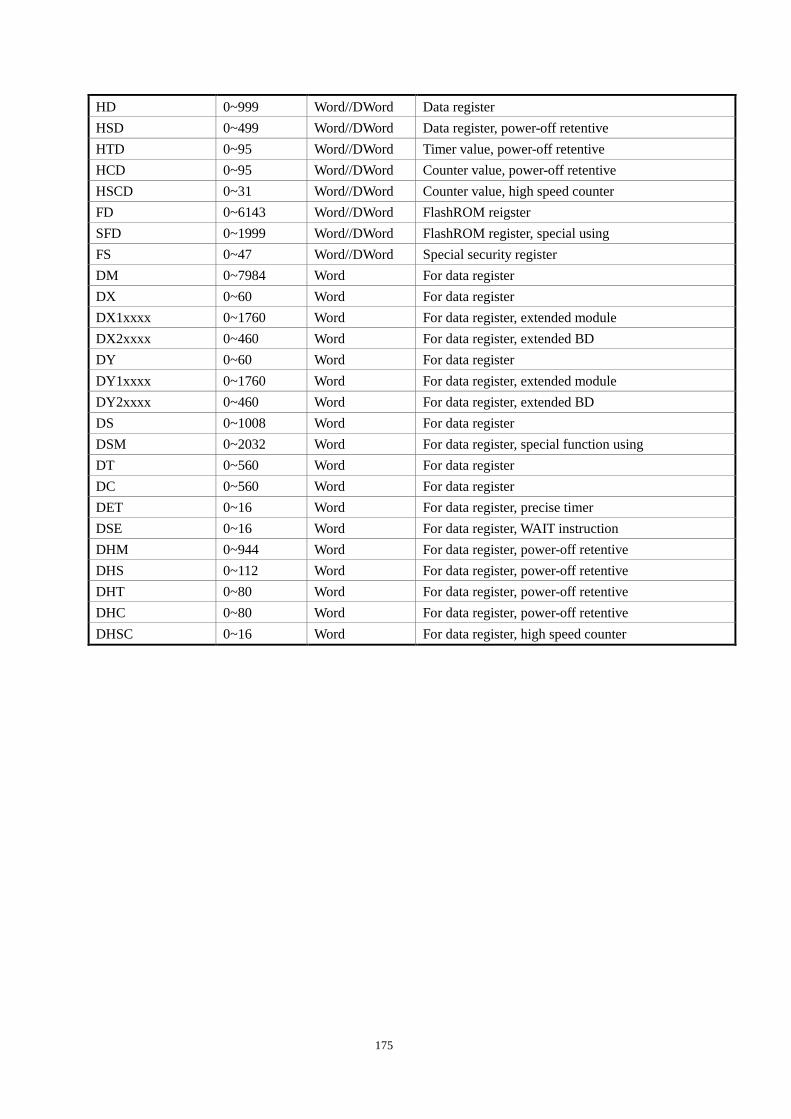
175
HD 0~999 Word//DWord Data register
HSD 0~499 Word//DWord Data register, power-off retentive
HTD 0~95 Word//DWord Timer value, power-off retentive
HCD 0~95 Word//DWord Counter value, power-off retentive
HSCD 0~31 Word//DWord Counter value, high speed counter
FD 0~6143 Word//DWord FlashROM reigster
SFD 0~1999 Word//DWord FlashROM register, special using
FS 0~47 Word//DWord Special security register
DM 0~7984 Word For data register
DX 0~60 Word For data register
DX1xxxx 0~1760 Word For data register, extended module
DX2xxxx 0~460 Word For data register, extended BD
DY 0~60 Word For data register
DY1xxxx 0~1760 Word For data register, extended module
DY2xxxx 0~460 Word For data register, extended BD
DS 0~1008 Word For data register
DSM 0~2032 Word For data register, special function using
DT 0~560 Word For data register
DC 0~560 Word For data register
DET 0~16 Word For data register, precise timer
DSE 0~16 Word For data register, WAIT instruction
DHM 0~944 Word For data register, power-off retentive
DHS 0~112 Word For data register, power-off retentive
DHT 0~80 Word For data register, power-off retentive
DHC 0~80 Word For data register, power-off retentive
DHSC 0~16 Word For data register, high speed counter
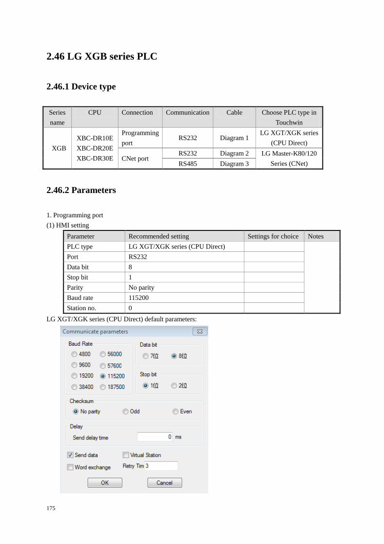
175
2.46 LG XGB series PLC
2.46.1 Device type
Series
name
CPU Connection Communication Cable Choose PLC type in
Touchwin
XGB
XBC-DR10E
XBC-DR20E
XBC-DR30E
Programming
port RS232 Diagram 1
LG XGT/XGK series
(CPU Direct)
CNet port RS232 Diagram 2 LG Master-K80/120
Series (CNet) RS485 Diagram 3
2.46.2 Parameters
1. Programming port
(1) HMI setting
Parameter Recommended setting Settings for choice Notes
PLC type LG XGT/XGK series (CPU Direct)
Port RS232
Data bit 8
Stop bit 1
Parity No parity
Baud rate 115200
Station no. 0
LG XGT/XGK series (CPU Direct) default parameters:
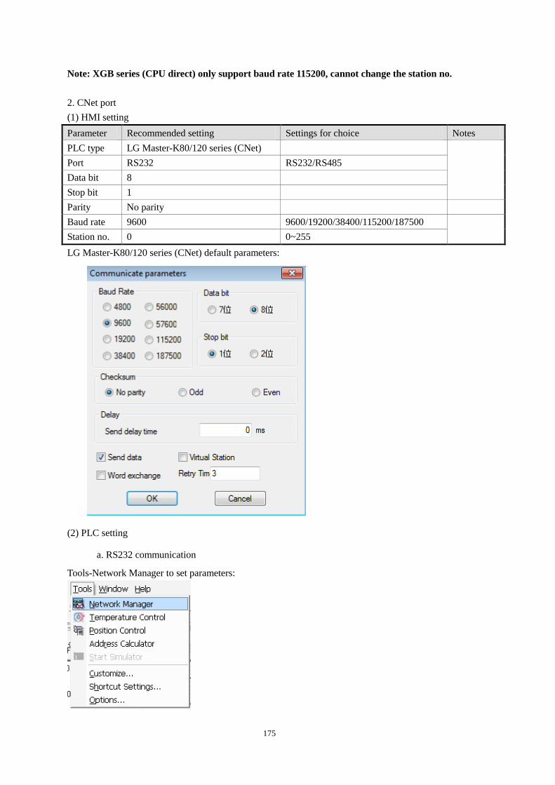
175
Note: XGB series (CPU direct) only support baud rate 115200, cannot change the station no.
2. CNet port
(1) HMI setting
Parameter Recommended setting Settings for choice Notes
PLC type LG Master-K80/120 series (CNet)
Port RS232 RS232/RS485
Data bit 8
Stop bit 1
Parity No parity
Baud rate 9600 9600/19200/38400/115200/187500
Station no. 0 0~255
LG Master-K80/120 series (CNet) default parameters:
(2) PLC setting
a. RS232 communication
Tools-Network Manager to set parameters:
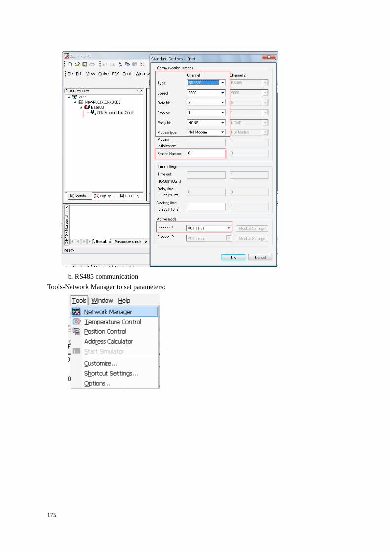
175
b. RS485 communication
Tools-Network Manager to set parameters:
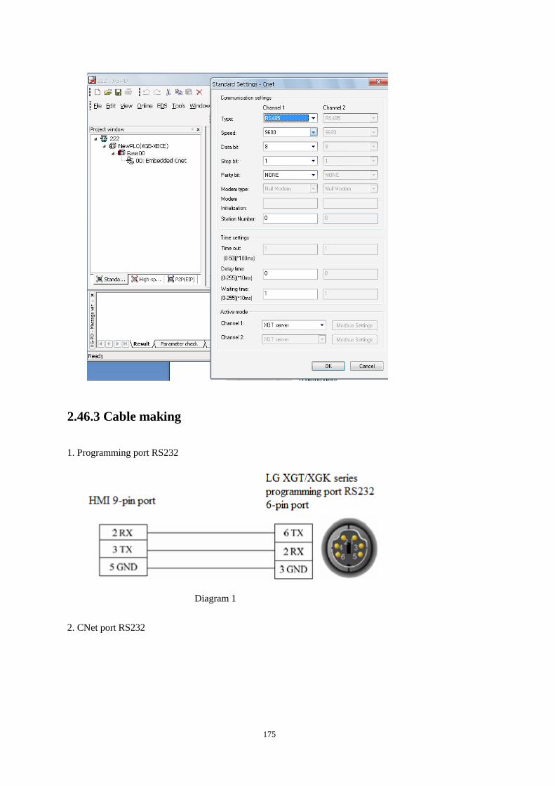
175
2.46.3 Cable making
1. Programming port RS232
Diagram 1
2. CNet port RS232
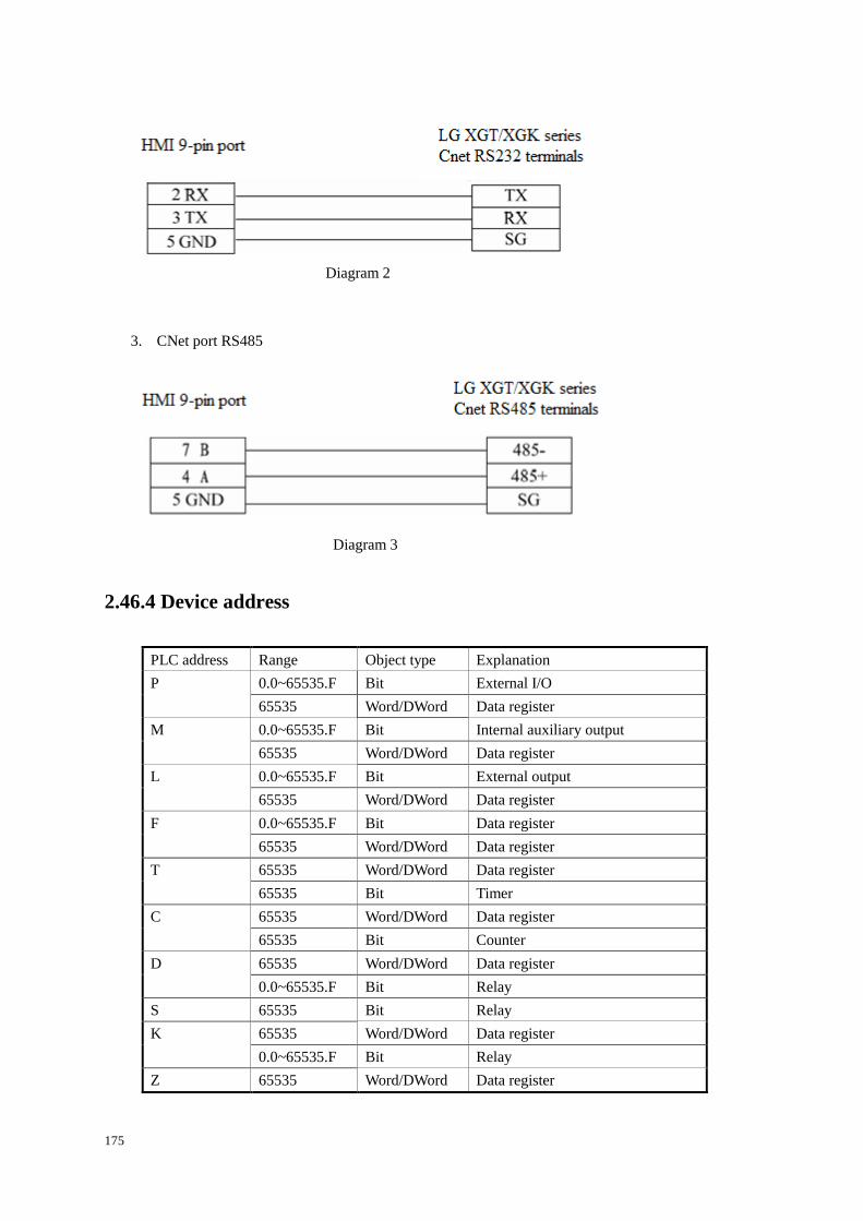
175
Diagram 2
3. CNet port RS485
Diagram 3
2.46.4 Device address
PLC address Range Object type Explanation
P 0.0~65535.F Bit External I/O
65535 Word/DWord Data register
M 0.0~65535.F Bit Internal auxiliary output
65535 Word/DWord Data register
L 0.0~65535.F Bit External output
65535 Word/DWord Data register
F 0.0~65535.F Bit Data register
65535 Word/DWord Data register
T 65535 Word/DWord Data register
65535 Bit Timer
C 65535 Word/DWord Data register
65535 Bit Counter
D 65535 Word/DWord Data register
0.0~65535.F Bit Relay
S 65535 Bit Relay
K 65535 Word/DWord Data register
0.0~65535.F Bit Relay
Z 65535 Word/DWord Data register
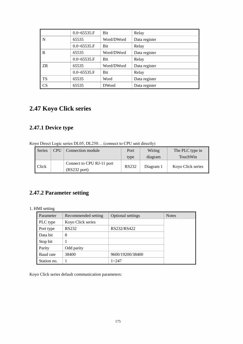
175
0.0~65535.F Bit Relay
N 65535 Word/DWord Data register
0.0~65535.F Bit Relay
R 65535 Word/DWord Data register
0.0~65535.F Bit Relay
ZR 65535 Word/DWord Data register
0.0~65535.F Bit Relay
TS 65535 Word Data register
CS 65535 DWord Data register
2.47 Koyo Click series
2.47.1 Device type
Koyo Direct Logic series DL05, DL250… (connect to CPU unit directly)
Series CPU Connection module Port
type
Wiring
diagram
The PLC type in
TouchWin
Click Connect to CPU RJ-11 port
(RS232 port) RS232 Diagram 1 Koyo Click series
2.47.2 Parameter setting
1. HMI setting
Parameter Recommended setting Optional settings Notes
PLC type Koyo Click series
Port type RS232 RS232/RS422
Data bit 8
Stop bit 1
Parity Odd parity
Baud rate 38400 9600/19200/38400
Station no. 1 1~247
Koyo Click series default communication parameters:
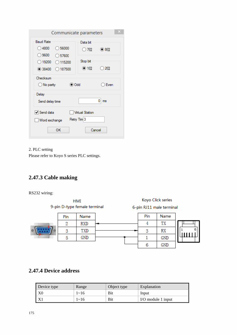
175
2. PLC setting
Please refer to Koyo S series PLC settings.
2.47.3 Cable making
RS232 wiring:
2.47.4 Device address
Device type Range Object type Explanation
X0 1~16 Bit Input
X1 1~16 Bit I/O module 1 input
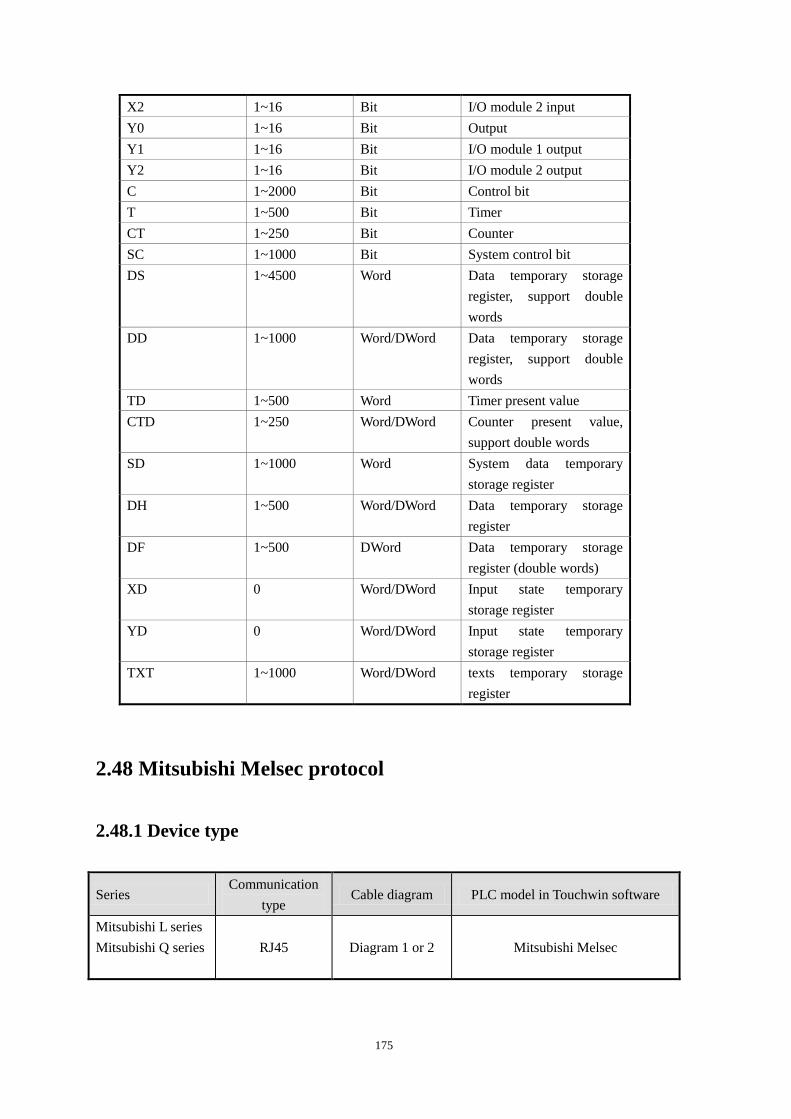
175
X2 1~16 Bit I/O module 2 input
Y0 1~16 Bit Output
Y1 1~16 Bit I/O module 1 output
Y2 1~16 Bit I/O module 2 output
C 1~2000 Bit Control bit
T 1~500 Bit Timer
CT 1~250 Bit Counter
SC 1~1000 Bit System control bit
DS 1~4500 Word Data temporary storage
register, support double
words
DD 1~1000 Word/DWord Data temporary storage
register, support double
words
TD 1~500 Word Timer present value
CTD 1~250 Word/DWord Counter present value,
support double words
SD 1~1000 Word System data temporary
storage register
DH 1~500 Word/DWord Data temporary storage
register
DF 1~500 DWord Data temporary storage
register (double words)
XD 0 Word/DWord Input state temporary
storage register
YD 0 Word/DWord Input state temporary
storage register
TXT 1~1000 Word/DWord texts temporary storage
register
2.48 Mitsubishi Melsec protocol
2.48.1 Device type
Series Communication
type Cable diagram PLC model in Touchwin software
Mitsubishi L series
Mitsubishi Q series
RJ45 Diagram 1 or 2 Mitsubishi Melsec
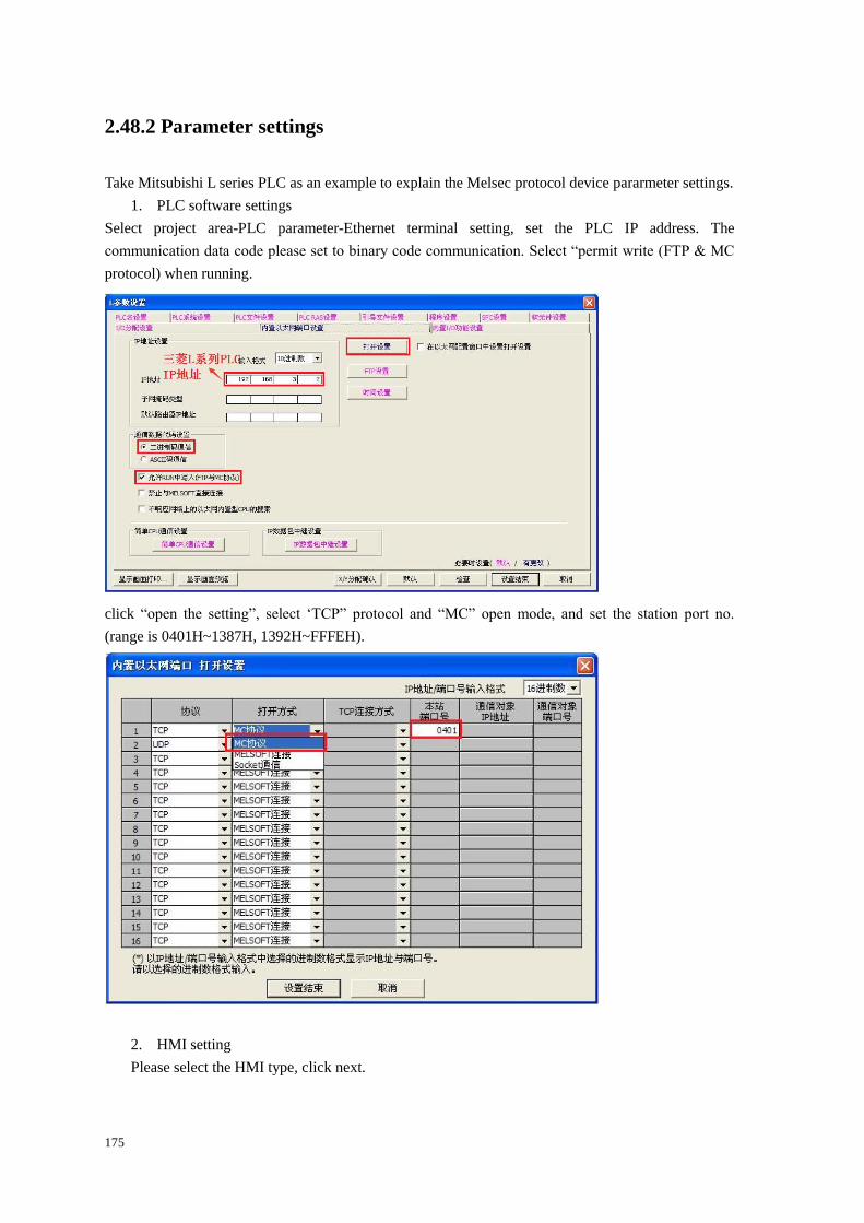
175
2.48.2 Parameter settings
Take Mitsubishi L series PLC as an example to explain the Melsec protocol device pararmeter settings.
1. PLC software settings
Select project area-PLC parameter-Ethernet terminal setting, set the PLC IP address. The
communication data code please set to binary code communication. Select “permit write (FTP & MC
protocol) when running.
click “open the setting”, select ‘TCP” protocol and “MC” open mode, and set the station port no.
(range is 0401H~1387H, 1392H~FFFEH).
2. HMI setting
Please select the HMI type, click next.
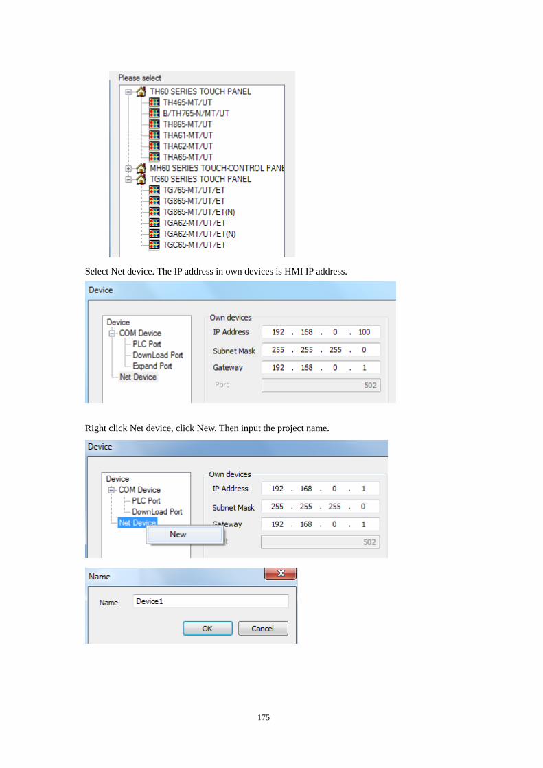
175
Select Net device. The IP address in own devices is HMI IP address.
Right click Net device, click New. Then input the project name.
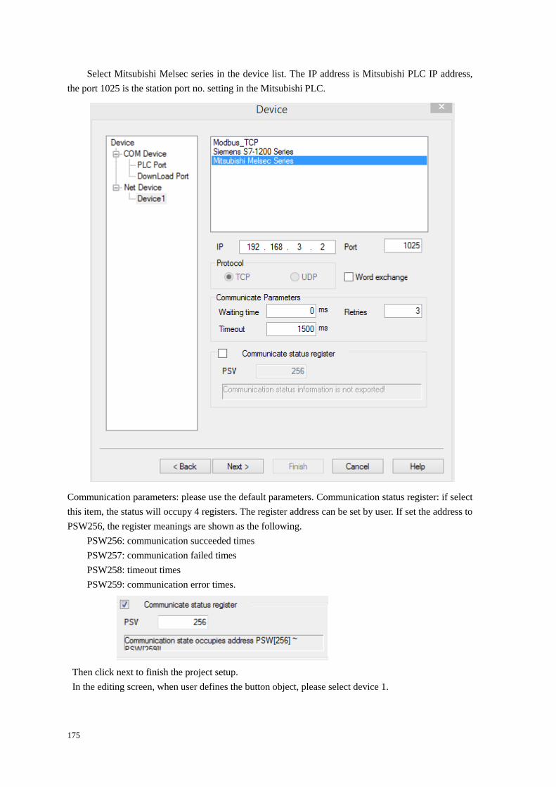
175
Select Mitsubishi Melsec series in the device list. The IP address is Mitsubishi PLC IP address,
the port 1025 is the station port no. setting in the Mitsubishi PLC.
Communication parameters: please use the default parameters. Communication status register: if select
this item, the status will occupy 4 registers. The register address can be set by user. If set the address to
PSW256, the register meanings are shown as the following.
PSW256: communication succeeded times
PSW257: communication failed times
PSW258: timeout times
PSW259: communication error times.
Then click next to finish the project setup.
In the editing screen, when user defines the button object, please select device 1.
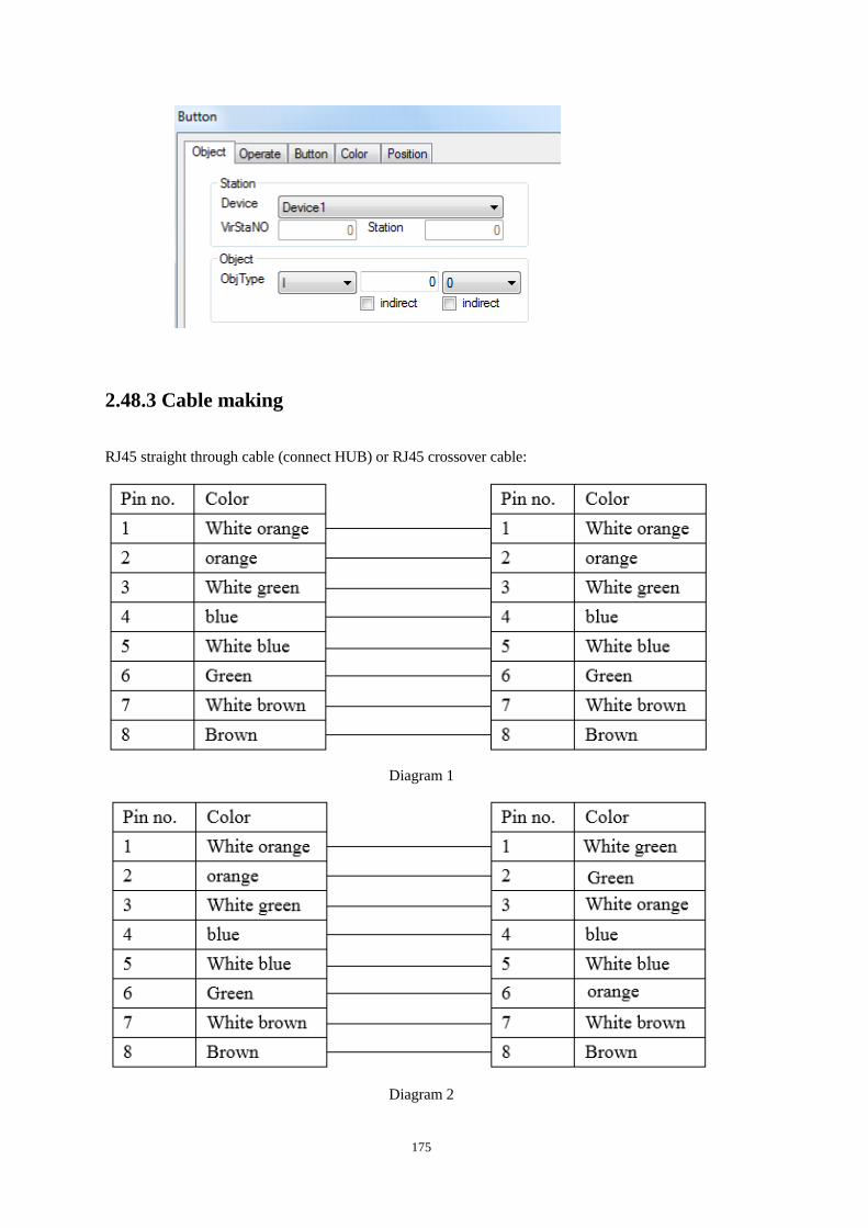
175
2.48.3 Cable making
RJ45 straight through cable (connect HUB) or RJ45 crossover cable:
Diagram 1
Diagram 2
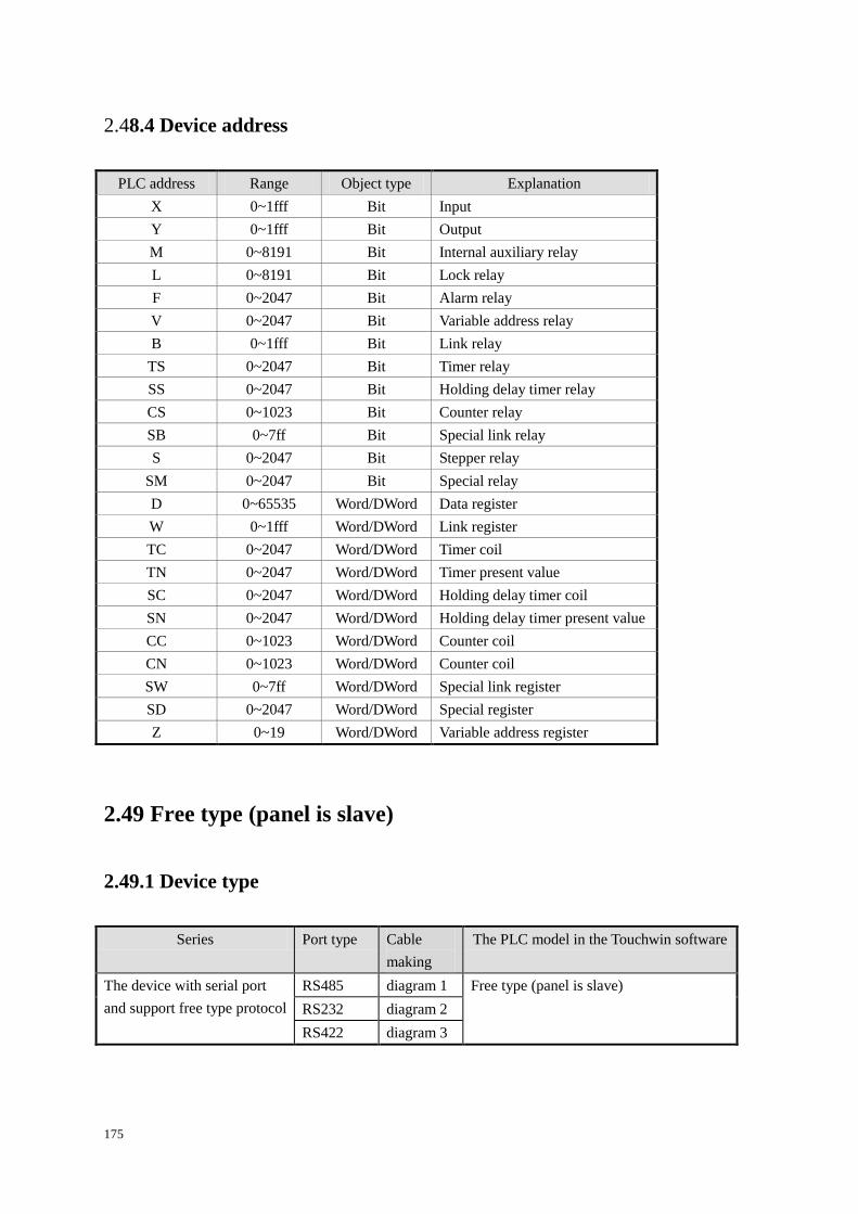
175
2.48.4 Device address
PLC address Range Object type Explanation
X 0~1fff Bit Input
Y 0~1fff Bit Output
M 0~8191 Bit Internal auxiliary relay
L 0~8191 Bit Lock relay
F 0~2047 Bit Alarm relay
V 0~2047 Bit Variable address relay
B 0~1fff Bit Link relay
TS 0~2047 Bit Timer relay
SS 0~2047 Bit Holding delay timer relay
CS 0~1023 Bit Counter relay
SB 0~7ff Bit Special link relay
S 0~2047 Bit Stepper relay
SM 0~2047 Bit Special relay
D 0~65535 Word/DWord Data register
W 0~1fff Word/DWord Link register
TC 0~2047 Word/DWord Timer coil
TN 0~2047 Word/DWord Timer present value
SC 0~2047 Word/DWord Holding delay timer coil
SN 0~2047 Word/DWord Holding delay timer present value
CC 0~1023 Word/DWord Counter coil
CN 0~1023 Word/DWord Counter coil
SW 0~7ff Word/DWord Special link register
SD 0~2047 Word/DWord Special register
Z 0~19 Word/DWord Variable address register
2.49 Free type (panel is slave)
2.49.1 Device type
Series Port type Cable
making
The PLC model in the Touchwin software
The device with serial port
and support free type protocol
RS485 diagram 1 Free type (panel is slave)
RS232 diagram 2
RS422 diagram 3
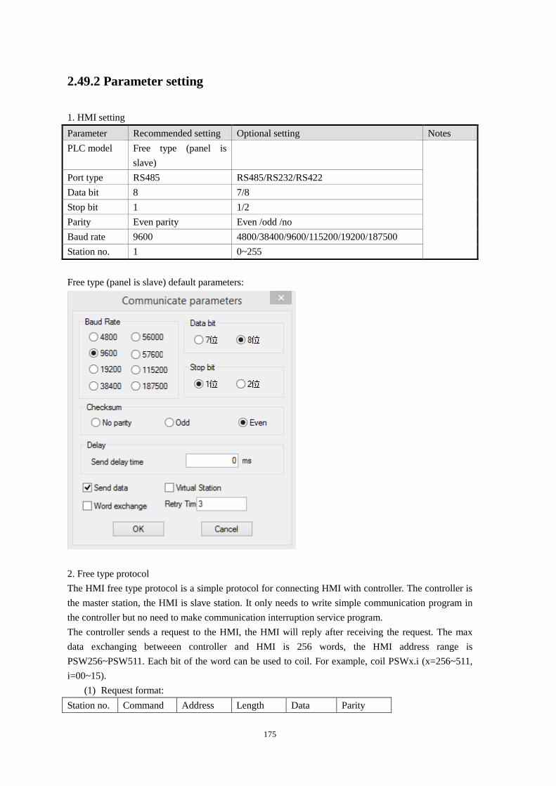
175
2.49.2 Parameter setting
1. HMI setting
Parameter Recommended setting Optional setting Notes
PLC model Free type (panel is
slave)
Port type RS485 RS485/RS232/RS422
Data bit 8 7/8
Stop bit 1 1/2
Parity Even parity Even /odd /no
Baud rate 9600 4800/38400/9600/115200/19200/187500
Station no. 1 0~255
Free type (panel is slave) default parameters:
2. Free type protocol
The HMI free type protocol is a simple protocol for connecting HMI with controller. The controller is
the master station, the HMI is slave station. It only needs to write simple communication program in
the controller but no need to make communication interruption service program.
The controller sends a request to the HMI, the HMI will reply after receiving the request. The max
data exchanging betweeen controller and HMI is 256 words, the HMI address range is
PSW256~PSW511. Each bit of the word can be used to coil. For example, coil PSWx.i (x=256~511,
i=00~15).
(1) Request format:
Station no. Command Address Length Data Parity
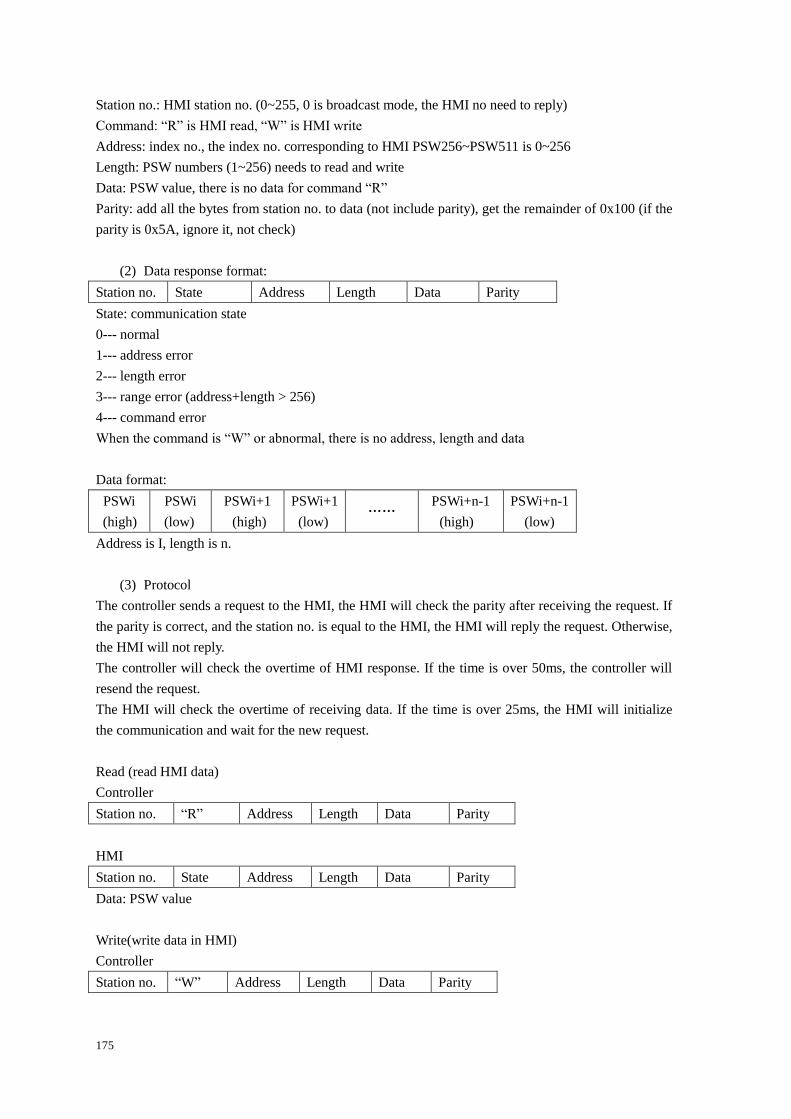
175
Station no.: HMI station no. (0~255, 0 is broadcast mode, the HMI no need to reply)
Command: “R” is HMI read, “W” is HMI write
Address: index no., the index no. corresponding to HMI PSW256~PSW511 is 0~256
Length: PSW numbers (1~256) needs to read and write
Data: PSW value, there is no data for command “R”
Parity: add all the bytes from station no. to data (not include parity), get the remainder of 0x100 (if the
parity is 0x5A, ignore it, not check)
(2) Data response format:
Station no. State Address Length Data Parity
State: communication state
0--- normal
1--- address error
2--- length error
3--- range error (address+length > 256)
4--- command error
When the command is “W” or abnormal, there is no address, length and data
Data format:
PSWi
(high)
PSWi
(low)
PSWi+1
(high)
PSWi+1
(low) ……
PSWi+n-1
(high)
PSWi+n-1
(low)
Address is I, length is n.
(3) Protocol
The controller sends a request to the HMI, the HMI will check the parity after receiving the request. If
the parity is correct, and the station no. is equal to the HMI, the HMI will reply the request. Otherwise,
the HMI will not reply.
The controller will check the overtime of HMI response. If the time is over 50ms, the controller will
resend the request.
The HMI will check the overtime of receiving data. If the time is over 25ms, the HMI will initialize
the communication and wait for the new request.
Read (read HMI data)
Controller
Station no. “R” Address Length Data Parity
HMI
Station no. State Address Length Data Parity
Data: PSW value
Write(write data in HMI)
Controller
Station no. “W” Address Length Data Parity
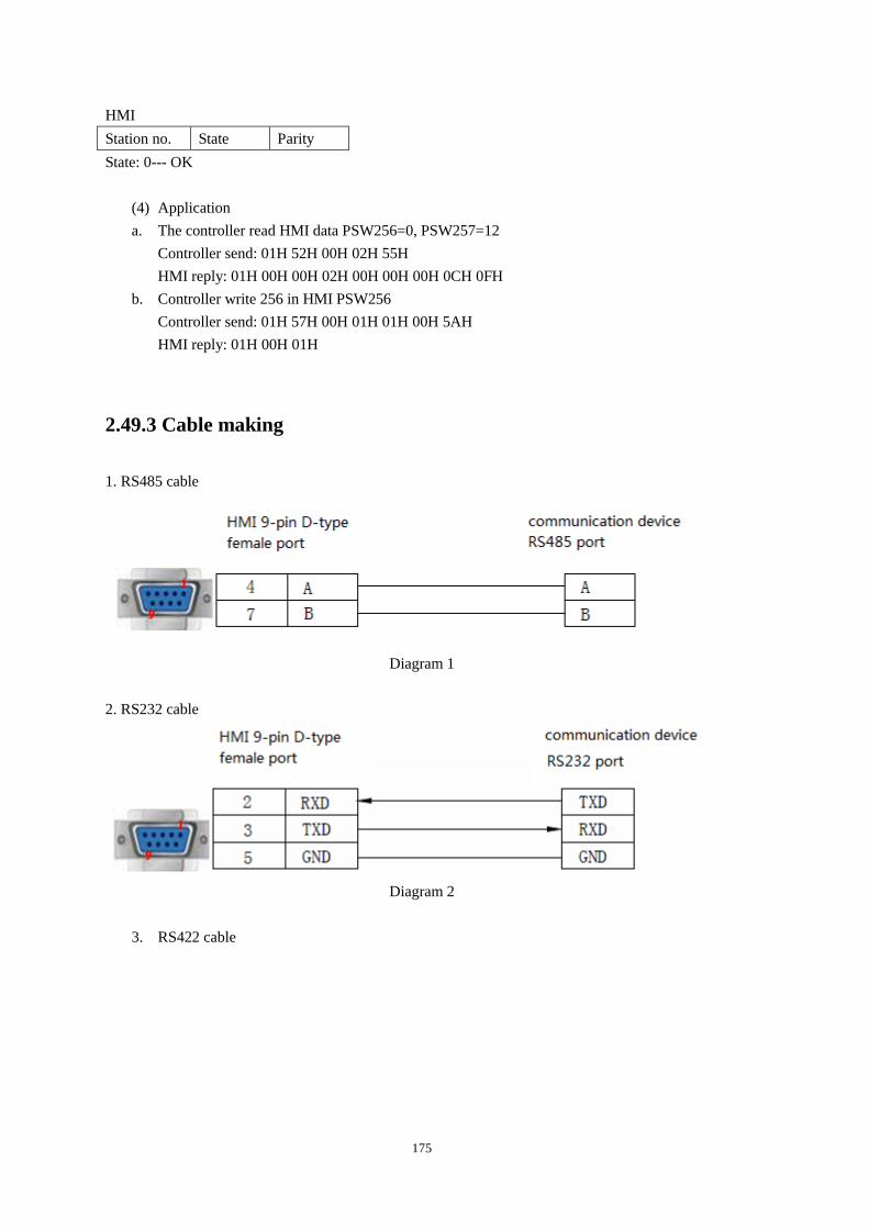
175
HMI
Station no. State Parity
State: 0--- OK
(4) Application
a. The controller read HMI data PSW256=0, PSW257=12
Controller send: 01H 52H 00H 02H 55H
HMI reply: 01H 00H 00H 02H 00H 00H 00H 0CH 0FH
b. Controller write 256 in HMI PSW256
Controller send: 01H 57H 00H 01H 01H 00H 5AH
HMI reply: 01H 00H 01H
2.49.3 Cable making
1. RS485 cable
Diagram 1
2. RS232 cable
Diagram 2
3. RS422 cable
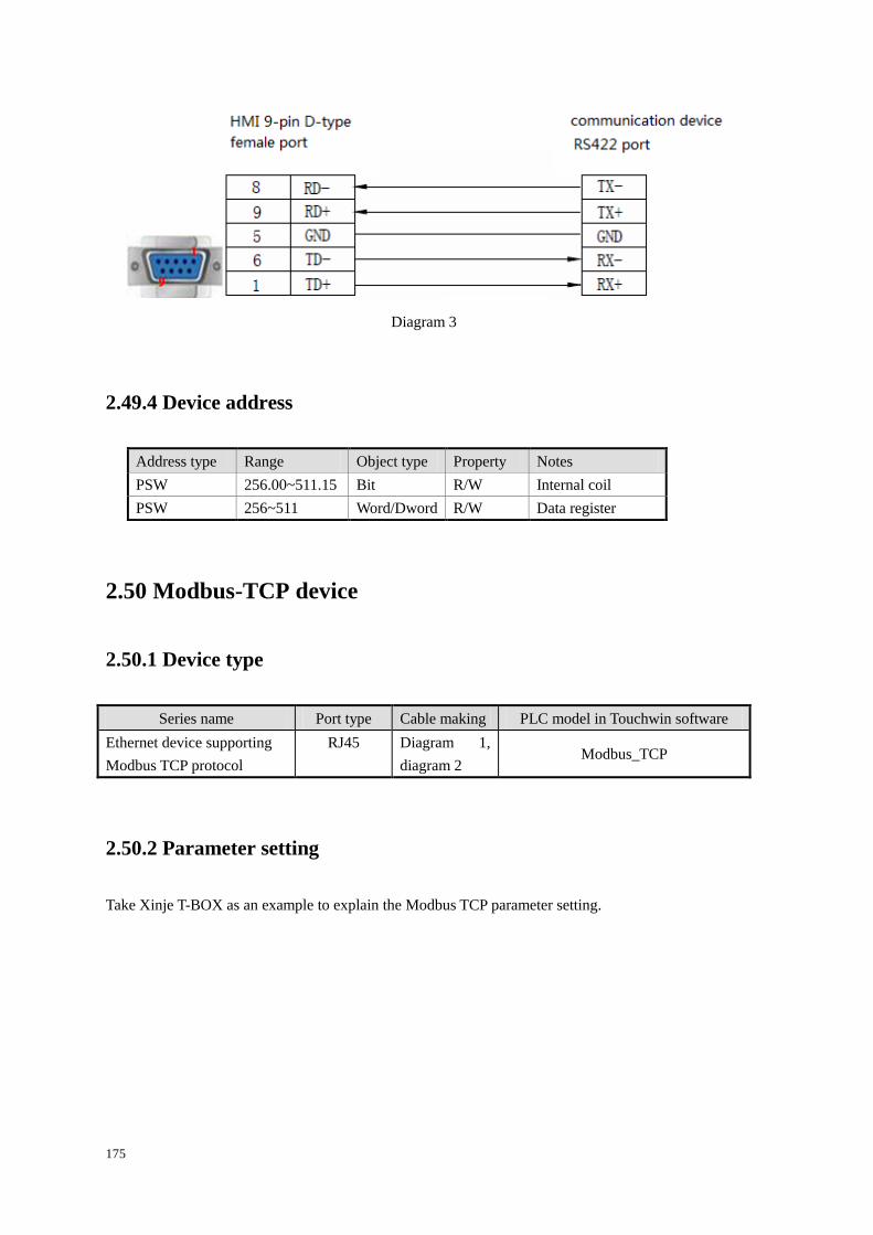
175
Diagram 3
2.49.4 Device address
Address type Range Object type Property Notes
PSW 256.00~511.15 Bit R/W Internal coil
PSW 256~511 Word/Dword R/W Data register
2.50 Modbus-TCP device
2.50.1 Device type
Series name Port type Cable making PLC model in Touchwin software
Ethernet device supporting
Modbus TCP protocol
RJ45 Diagram 1,
diagram 2 Modbus_TCP
2.50.2 Parameter setting
Take Xinje T-BOX as an example to explain the Modbus TCP parameter setting.
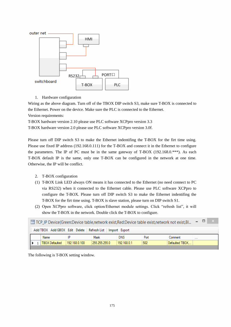
175
1. Hardware configuration
Wiring as the above diagram. Turn off of the TBOX DIP switch S3, make sure T-BOX is connected to
the Ethernet. Power on the device. Make sure the PLC is connected to the Ethernet.
Version requirements:
T-BOX hardware version 2.10 please use PLC software XCPpro version 3.3
T-BOX hardware version 2.0 please use PLC software XCPpro version 3.0f.
Please turn off DIP switch S3 to make the Ethernet indentifing the T-BOX for the firt time using.
Please use fixed IP address (192.168.0.111) for the T-BOX and connect it in the Ethernet to configure
the parameters. The IP of PC must be in the same gateway of T-BOX (192.168.0.***). As each
T-BOX default IP is the same, only one T-BOX can be configured in the network at one time.
Otherwise, the IP will be conflict.
2. T-BOX configuration
(1) T-BOX Link LED always ON means it has connected to the Ethernet (no need connect to PC
via RS232) when it connected to the Ethernet cable. Please use PLC software XCPpro to
configure the T-BOX. Please turn off DIP switch S3 to make the Ethernet indentifing the
T-BOX for the firt time using. T-BOX is slave station, please turn on DIP switch S1.
(2) Open XCPpro software, click option/Ethernet module settings. Click “refresh list”, it will
show the T-BOX in the network. Double click the T-BOX to configure.
The following is T-BOX setting window.
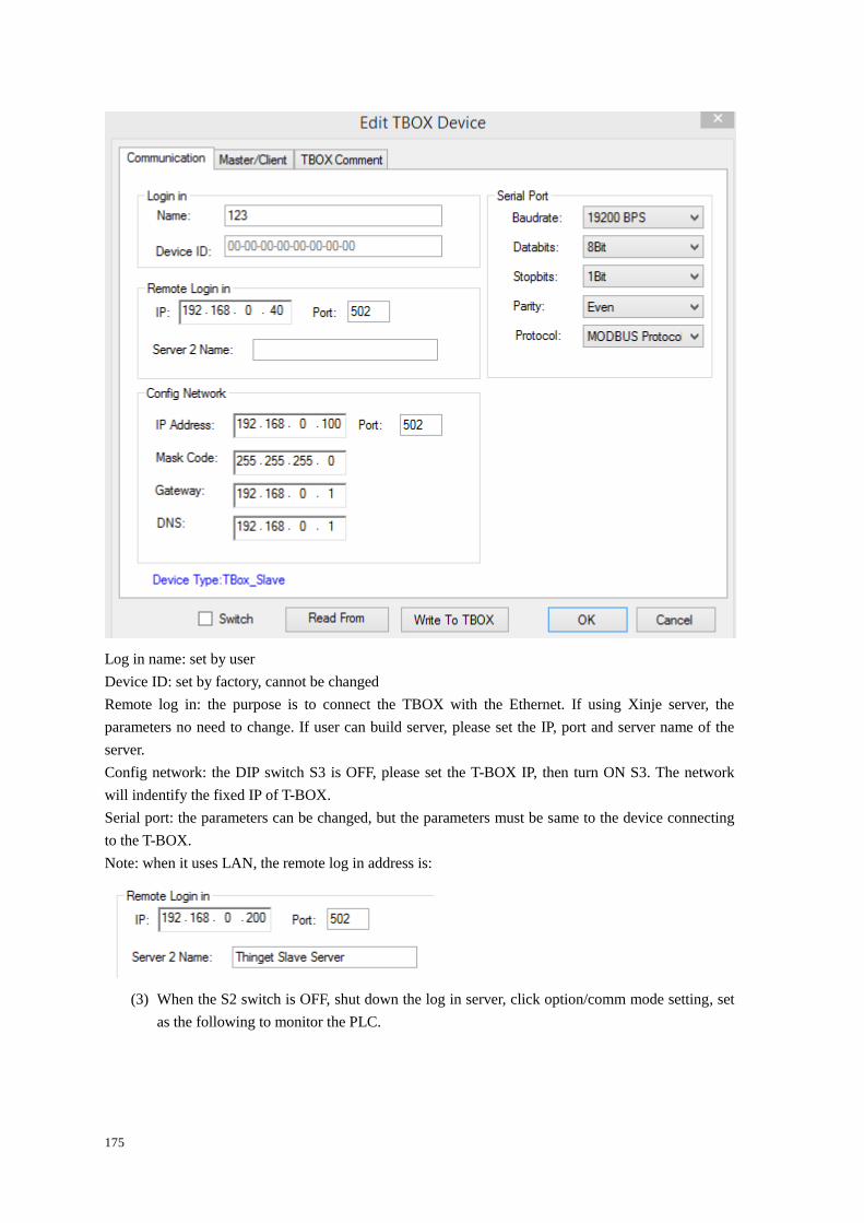
175
Log in name: set by user
Device ID: set by factory, cannot be changed
Remote log in: the purpose is to connect the TBOX with the Ethernet. If using Xinje server, the
parameters no need to change. If user can build server, please set the IP, port and server name of the
server.
Config network: the DIP switch S3 is OFF, please set the T-BOX IP, then turn ON S3. The network
will indentify the fixed IP of T-BOX.
Serial port: the parameters can be changed, but the parameters must be same to the device connecting
to the T-BOX.
Note: when it uses LAN, the remote log in address is:
(3) When the S2 switch is OFF, shut down the log in server, click option/comm mode setting, set
as the following to monitor the PLC.
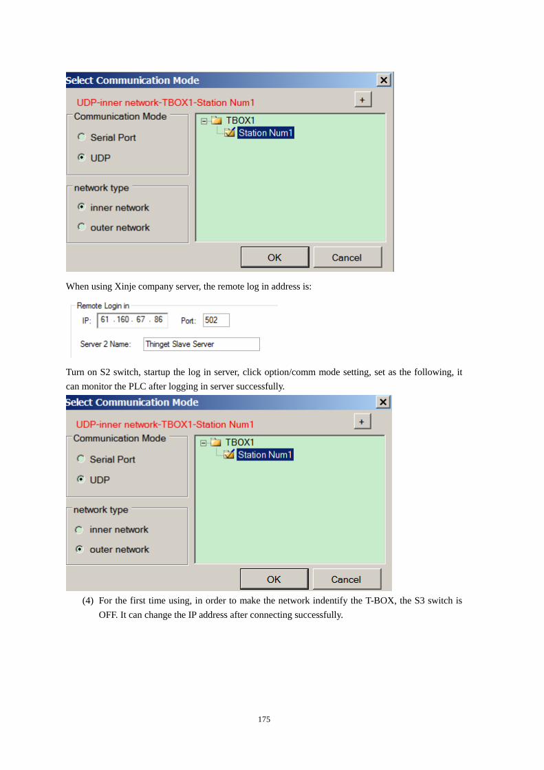
175
When using Xinje company server, the remote log in address is:
Turn on S2 switch, startup the log in server, click option/comm mode setting, set as the following, it
can monitor the PLC after logging in server successfully.
(4) For the first time using, in order to make the network indentify the T-BOX, the S3 switch is
OFF. It can change the IP address after connecting successfully.
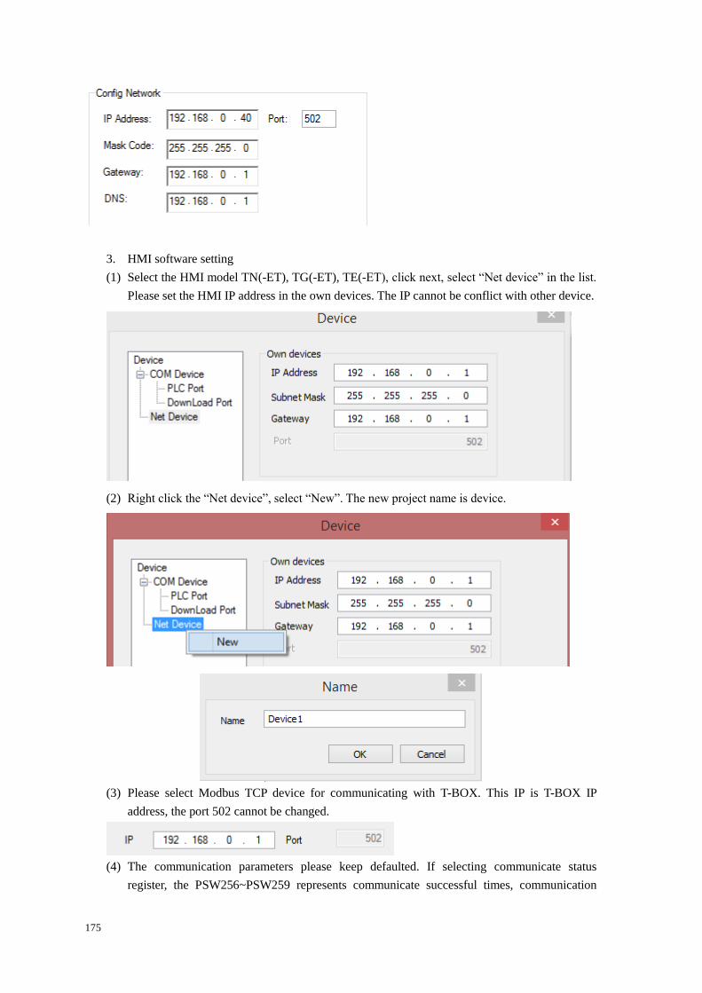
175
3. HMI software setting
(1) Select the HMI model TN(-ET), TG(-ET), TE(-ET), click next, select “Net device” in the list.
Please set the HMI IP address in the own devices. The IP cannot be conflict with other device.
(2) Right click the “Net device”, select “New”. The new project name is device.
(3) Please select Modbus TCP device for communicating with T-BOX. This IP is T-BOX IP
address, the port 502 cannot be changed.
(4) The communication parameters please keep defaulted. If selecting communicate status
register, the PSW256~PSW259 represents communicate successful times, communication
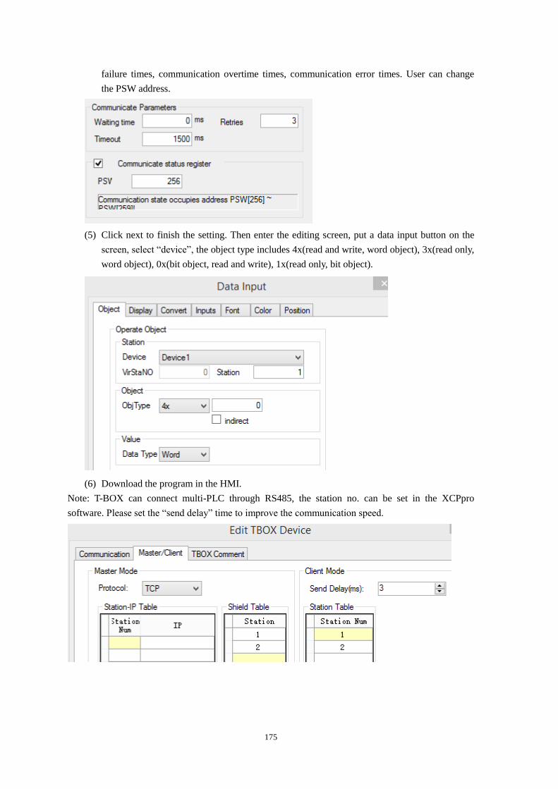
175
failure times, communication overtime times, communication error times. User can change
the PSW address.
(5) Click next to finish the setting. Then enter the editing screen, put a data input button on the
screen, select “device”, the object type includes 4x(read and write, word object), 3x(read only,
word object), 0x(bit object, read and write), 1x(read only, bit object).
(6) Download the program in the HMI.
Note: T-BOX can connect multi-PLC through RS485, the station no. can be set in the XCPpro
software. Please set the “send delay” time to improve the communication speed.
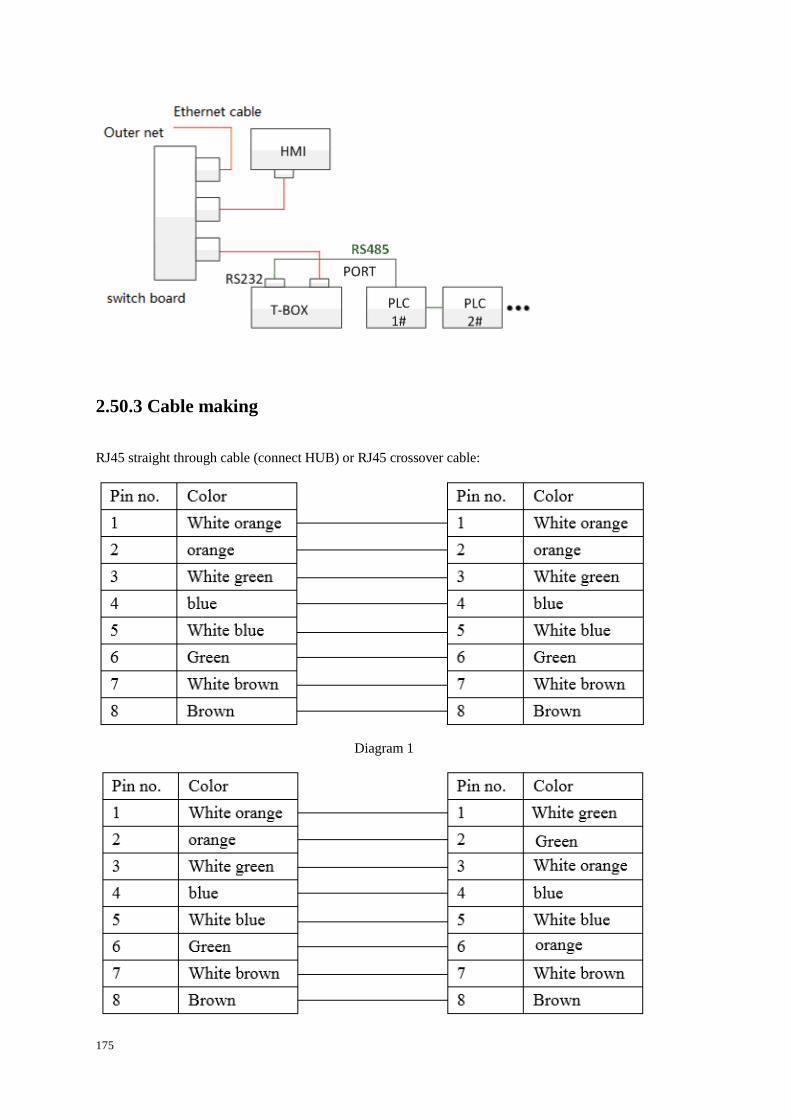
175
2.50.3 Cable making
RJ45 straight through cable (connect HUB) or RJ45 crossover cable:
Diagram 1
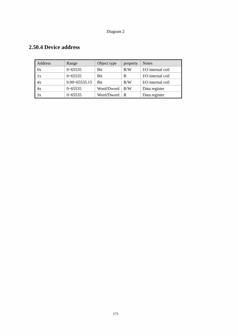
175
Diagram 2
2.50.4 Device address
Address Range Object type property Notes
0x 0~65535 Bit R/W I/O internal coil
1x 0~65535 Bit R I/O internal coil
4x 0.00~65535.15 Bit R/W I/O internal coil
4x 0~65535 Word/Dword R/W Data register
3x 0~65535 Word/Dword R Data register

175
WUXI XINJE ELECTRIC CO., LTD.
4th Floor, Building 7th, No.100 Dicui
Rd, Wuxi, China
Tel: 86-0510-85134139
Fax: 86-0510-85111290
www.xinje.com
Email: [email protected]