HLR-1000E: TECHNICAL SPECIFICATIONS/media/jci/be/united-states/airside... · The HLR 1000E...
16
© York. All rights reserved. 10/7/15 v 1.8 HLR-1000E: TECHNICAL SPECIFICATIONS
Transcript of HLR-1000E: TECHNICAL SPECIFICATIONS/media/jci/be/united-states/airside... · The HLR 1000E...

© York. All rights reserved.
10/7/15 v 1.8
HLR-1000E:
TECHNICAL SPECIFICATIONS

HLR 1000E Technical Specifications
© York. All rights reserved. 2
Table of Contents
Introduction ................................................................................................................................................ 3 The Problem the HLR Addresses ............................................................................................................ 3
HLR Overview: The System, the Module and the Sorbents ...................................................................... 4 The HLR System ...................................................................................................................................... 4 The HLR 1000E Module .......................................................................................................................... 4 The Sorbents ........................................................................................................................................... 5
Functionality and Benefits .......................................................................................................................... 5 Functionality ........................................................................................................................................... 5 Benefits ................................................................................................................................................... 6
Component Location and Description ........................................................................................................ 8 Air Flow Capacity ........................................................................................................................................ 9 Weight and Dimensions ........................................................................................................................... 10 Electrical Panel ......................................................................................................................................... 10
a. Power Requirements .................................................................................................................... 10 b. Communications ........................................................................................................................... 11 c. Fans & Heaters ............................................................................................................................. 11 d. Built-in Connections - Required .................................................................................................... 11 e. Built-in Connections – Additional Available Connections ............................................................ 12 f. Sensors ......................................................................................................................................... 12
Description of HLR 1000E Modes ............................................................................................................. 12 Monitoring and Reporting ........................................................................................................................ 13 Annual Maintenance - Cartridge Set Replacement .................................................................................. 13 Installation Specifications ......................................................................................................................... 13 ASHRAE Standard 62.1 Compliance ......................................................................................................... 16 Support ..................................................................................................................................................... 16
HLR 1000E Technical Specifications
© York. All rights reserved. 3
Introduction
The York HVAC Load Reduction (HLR™) module is a 'smart scrubber' that replaces costly ventilation
control methods with a practical, proven, energy-saving approach using the latest advances in
materials and chemical engineering as well as digital technology. By treating the indoor air, York's innovative HLR solution minimizes the amount of outdoor air required to maintain indoor air quality
(IAQ) and thereby reduces the load on the HVAC system and its energy consumption.
The HLR 1000E offers the benefits of double-digit energy savings while maintaining indoor air quality
(IAQ) and is an ‘all season’ system, automatically managing HVAC cooling and heating loads. The HLR
1000E is a closed-loop design with each module having an integrated heating, mechanical, electrical,
and communication system.
The Problem the HLR Addresses
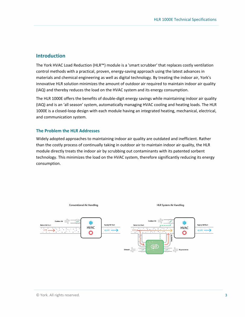
Widely adopted approaches to maintaining indoor air quality are outdated and inefficient. Rather
than the costly process of continually taking in outdoor air to maintain indoor air quality, the HLR
module directly treats the indoor air by scrubbing out contaminants with its patented sorbent
technology. This minimizes the load on the HVAC system, therefore significantly reducing its energy
consumption.

HLR 1000E Technical Specifications
© York. All rights reserved. 4
HLR Overview: The System, the Module and the Sorbents
The HLR System
The system is a group of networked HLR 1000E Modules installed in the mechanical rooms or indoor
air plenums in a building. The HLR 1000E incorporates state-of-the-art wireless technology for peer-to-
peer and cloud connectivity enabling enhanced real-time monitoring, reporting and system results
validation.
The HLR 1000E Module
A fully self-contained mechanical design with easy side-
by-side retrofit to existing HVAC infrastructure.
All season module; heating and cooling
Designed to maximize energy efficiency & savings
Operates using standard single-phase power
Light-weight, easy to install
HLR 1000E Technical Specifications
© York. All rights reserved. 5
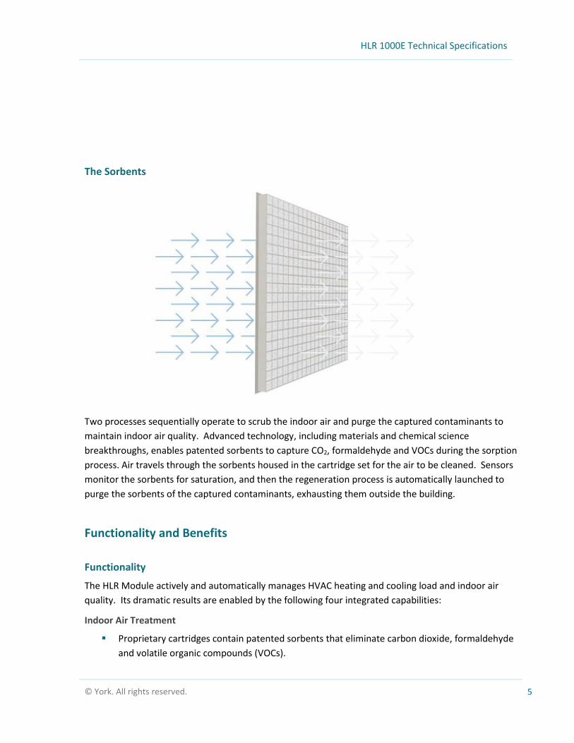
The Sorbents
Two processes sequentially operate to scrub the indoor air and purge the captured contaminants to
maintain indoor air quality. Advanced technology, including materials and chemical science
breakthroughs, enables patented sorbents to capture CO2, formaldehyde and VOCs during the sorption
process. Air travels through the sorbents housed in the cartridge set for the air to be cleaned. Sensors
monitor the sorbents for saturation, and then the regeneration process is automatically launched to
purge the sorbents of the captured contaminants, exhausting them outside the building.
Functionality and Benefits
Functionality
The HLR Module actively and automatically manages HVAC heating and cooling load and indoor air
quality. Its dramatic results are enabled by the following four integrated capabilities:
Indoor Air Treatment
Proprietary cartridges contain patented sorbents that eliminate carbon dioxide, formaldehyde
and volatile organic compounds (VOCs).

HLR 1000E Technical Specifications
© York. All rights reserved. 6
Embedded sensors continually monitor indoor air quality, sorbent performance and system
operating conditions to ensure optimal IAQ management.
Automated Regeneration
Several times a day, cartridges are ‘regenerated’, causing the sorbents to release the captured
contaminants to the outside of the building.
Regeneration is scheduled, managed and timed for automatic performance and minimal
energy use.
Outside Air Management
Electromechanical control of the HVAC system’s outside air damper minimizes the amount of
outside air ventilation based on energy and air quality considerations.
Automatic fail-safe setting in case of fire emergency, power outage or malfunction.
Monitoring and Reporting
Built-in electronics and software, including networking for online internet connectivity,
engineered to control, record and report all aspects of the HLR system operation.
Sophisticated proprietary algorithms designed to maximize energy savings.
Benefits
The HLR 1000E Module delivers significant energy savings while maintaining indoor air quality. The
benefits of the HLR solution include:
Load Reduction and Energy Savings
Over 40% reduction in peak power load
20% average energy cost savings (heating and/or cooling)
Indoor Air Quality
The only commercial solution that effectively addresses CO2, formaldehyde and VOCs
Dramatically reduced intake of outdoor pollutants
Real-time Monitoring, Reporting and Validation
24/7 online access to performance metrics including air quality and real-time, validated energy
savings
Remote control of the system at your fingertips by computer or smart phone
Scalability and Flexibility
HLR 1000E Technical Specifications
© York. All rights reserved. 7
Easy side-by-side retrofit with existing HVAC infrastructure
A network of multiple HLR modules offers a scalable solution for any building
Simple, turn-key installation; vertical or horizontal installation; fits through standard doorway;
lightweight
Requires minimal labor for installation
Reliability
Minimal routine maintenance; cartridge set replacement only once a year
Robust design delivers 20+ year operating life
Compliance and Sustainability
Meets ASHRAE Standard 62.1 for ventilation and indoor air quality
Qualifies for U.S. Green Business Council LEED credits

HLR 1000E Technical Specifications
© York. All rights reserved. 8
Component Location and Description
The HLR 1000E works in all climates. Each HLR 1000E Module is a self-contained cabinet pre-assembled
with the following components:
A. Cartridge Bank – The cartridge bank houses a set of twelve cartridges which contain the
sorbents that collect select contaminants (CO2, formaldehyde and VOCs) during the sorption
(cleansing) cycle and then release the captured contaminants during the regeneration
(outdoor purge) cycle. Cartridges are constructed in polypropylene further reducing total
weight of the unit.
B. Heater – The integrated heater raises the internal temperature of the HLR 1000E to initiate the
process of releasing the captured contaminants. During this time all external dampers are
closed, and air is re-circulated inside the HLR 1000E to accelerate the release process.
B. Heater
A. Cartridge Bank
C. Fans
F. Control Board
D. Inlets and Outlets
G. Sensors(Quad Sensor)
E. Shunt
H. Insulation (shown in green)
HLR 1000E Technical Specifications
© York. All rights reserved. 9
C. Fans – Integrated DC brushless fans control the airflow through the HLR 1000E during the
sorption and regeneration cycles. The controller has speed control and active feedback from
the fans verifying correct operation.
D. Inlets and Outlets – The HLR 1000E Module has 2 circular inlets and two circular outlets
controlled by dampers. The inlets that route the air during sorption are highlighted in green.
The outlets that route the air during the purge portion of the regeneration cycle are
highlighted in red.
E. The internal Shunt that is used during the heating portion of the regeneration cycle is
controlled by a damper that is only open when all other dampers are closed.
F. Control Board – The electronic enclosure contains the HLR 1000E power supply and the
controller board. The power supply converts the incoming AC power to the necessary voltages
to operate all aspects of the unit. The controller contains the systems software, all
controls/relays/sensor interfaces, as well as all wireless and wired communication modules.
G. Sensors – The HLR 1000E unit contains three integrated internal multi-sensor modules used to
measure temperature, humidity, CO2 concentration, formaldehyde and VOC levels during the
sorption and regeneration cycles. The HLR 1000E has two additional temperature and humidity
sensors for monitoring the incoming outside air and the supply air from the air handling unit
(AHU) to the conditioned space.
H. Insulation – The inside walls of the HLR 1000E unit are covered in heat-reflective insulation
material for improved efficiency of the unit and soundproofing.
Air Flow Capacity
The HLR 1000E is designed to handle up to 1000 CFM (cubic feet per minute) of air in a slipstream
configuration drawn from the return air path of the HVAC system. The number of modules required
for any given building is determined by multiple considerations including contaminant sources, floor
space, occupancy, exhaust systems and building pressurization. A typical guideline for office buildings
is to have one HLR 1000E for approximately every 20,000 square feet of floor space, however only a
qualified HLR installation professional can determine the correct number and configuration of units
required.

HLR 1000E Technical Specifications
© York. All rights reserved. 10
Weight and Dimensions
Weight lbs (kg)
Unit Cabinet 200 (90.7)
Unit with Cartridge Set 400 (181.4)
Dimensions Unit Unit with Dampers
& Handles
Length 50” (128 cm) 43”(110 cm)
Width 27 “ (68 cm) 25 “ (63 cm)
Height 74” (187 cm) 68” (172 cm)
Electrical Panel
a. Power Requirements
The HLR is designed to work with single phase AC power and can accommodate a range of
line voltages and frequencies.
Supply Main 208 – 277VAC/50-60Hz/16A

HLR 1000E Technical Specifications
© York. All rights reserved. 11
b. Communications
Each HLR 1000E module includes wireless communication capabilities for ongoing
monitoring and reporting of indoor air quality, sorbent performance and system operating
conditions. This wireless link is a state-of-the art solution with a long-range reach and
ultralow power consumption. The HLR 1000E is able to communicate with all BACnet™
based building management systems.
Communications Cellular Link 2.5G/3G
Wireless Link 915 MHz
BACnet over MSTP ISO-RS485
c. Fans & Heaters
Powerful, light-weight digitally controlled fans combined with an integrated heater deliver
an effective and efficient variable air flow solution.
Voltage/Power
Air Flow Components Fan(s) 24VDC/72W (each)
Heater with PID control 277VAC/6.5kW
d. Built-in Connections - Required
The HLR 1000E interfaces to the AHU (air handling unit) using the required built-in
connections listed below. The minimum number of connections in order to operate the
HLR 1000E with an AHU are as follows:
1. Outside Air Damper Actuator – The HLR 1000E must take control of the Outside
Air Damper actuator. This is the key factor that enables the energy savings and
load management when using the HLR 1000E.
2. Outside Air Damper Reading – The HLR 1000E requires reading the position signal
from the OA damper to ensure that the HLR 1000E is setting the damper to the
correct position.
3. Fire Signal – The fire signal is commonly generated from the fire panel or building
automation system in the event of a fire in the building and is used to put the
outside air damper and the HLR 1000E and other air handling devices in a mode

HLR 1000E Technical Specifications
© York. All rights reserved. 12
that will inhibit smoke/fire from spreading throughout the building through the air
ducts.
4. Air Handler Mode – The HLR 1000E operates in conjunction with the AHU.
Connections OA Damper Control Output from HLR 1000E: 2-10 VDC
OA Damper Position Monitoring
Output from HLR 1000E: 2-10 VDC
Fire Signal Dry Contact Input Input to HLR 1000E
AHU Mode Input Input to HLR 1000E
e. Built-in Connections – Additional Available Connections
Connections AHU Fan Speed Input Input to HLR 1000E
BAS* Open OA Damper Input Input to HLR 1000E
BAS Close OA Damper Input Input to HLR 1000E
Energy Meter D Input Input to HLR 1000E
Available 24 V Relay Output Output from HLR 1000E 24V/1A
Available Dry Contact Output Output from HLR 1000E 1A (max)
Available Dry Contact Input Input to HLR 1000E
*BAS - Building Automation System
f. Sensors
Sensor Function Location Measurement*
Multi Sensor Measures incoming air HLR Interior T,RH, IAQ
TRH Sensor - AHU These sensors measure energy use
SA Duct T,RH
OA Duct T,RH
Pressure Sensor Measures pressure HLR Interior P
Sorbent Temp Measures temperature during regeneration
HLR Interior T
*Legend: T (temperature); RH (relative humidity); IAQ (Air Quality); P (pressure)
Description of HLR 1000E Modes
Sorption Mode – The HLR 1000E forces air to pass through the sorbents, capturing CO2,
formaldehyde and VOCs, and returns the cleansed air back into the airstream.
Regeneration Mode – The HLR 1000E is disconnected from the normal airstream, purging the
sorbents with heated air and exhausting contaminants outside the building.
HLR 1000E Technical Specifications
© York. All rights reserved. 13
Standby Mode – When not in an active mode, the HLR 1000E does not carry air flow, but does
continue to monitor its air quality sensors.
Monitoring and Reporting
Each HLR 1000E Module has built-in electronics and software to record and report all aspects of the
HLR system operation. A custom SCADA (supervisory control and data acquisition) interface
allows users to view real-time and historical data to monitor IAQ and energy savings results.
Authorized users have a login with defined permission levels providing access to a website
where results can be monitored. The data is uploaded via a wireless link.
Annual Maintenance - Cartridge Set Replacement
The HLR 1000E module is designed to require minimal on-site routine maintenance. Annual cartridge
set replacement is the only required standard maintenance. This can be performed by any certified
technician. With ongoing maintenance, the HLR 1000E modules are designed for a long operating life
of 20+ years.
Cartridge storage
HLR cartridge sets should be stored indoors away from direct sunlight in -10 °C to +35 °C (14°F to
95°F). Cartridges should be kept in their plastic wrap to protect them from moisture or damage prior
to installation.
Recycling of cartridges
When cartridges are replaced, the used cartridges should be placed in the packaging from the
replacement cartridges, sealed, and shipped back using the return mailing label provided in the
cartridge packaging.
Installation Specifications
The HLR 1000E is designed for simple, turn-key installation.
Simple Installation - the HLR 1000E is designed for simple installation with physical dimensions
enabling each unit to fit through a standard doorway; its light weight provides for easy
transportation and positioning. Three requirements:

HLR 1000E Technical Specifications
© York. All rights reserved. 14
1. Electrical power
2. A wireless data connection is built-in; for a wired connection, cable must be hooked up
during installation.
3. Air duct connections. The round control dampers ensure quick and cost-effective installation
to ducts without needing transitions.
The HLR 1000E can be installed by one person in approximately 30 minutes.
Indoor installation - durable finish, sturdy construction and reflective insulation make the HLR
1000E compatible with indoor installations. The modules can be located anywhere in the
general vicinity of the Air Handling Unit (AHU), in the building’s mechanical rooms.
Vertical or horizontal installation for easy side-by-side retrofit to existing HVAC infrastructure
Two options for installation:
Case I: Ducted Return
Case II: Plenum Return
Case I: Ducted Return
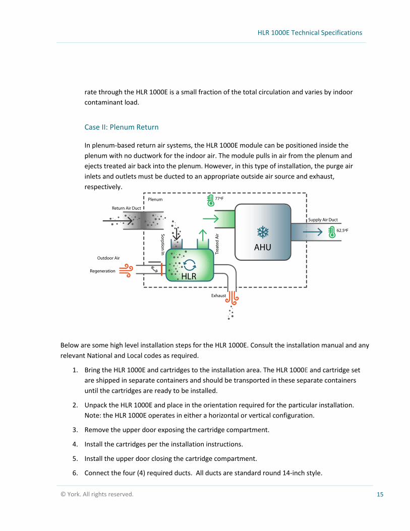
The HLR 1000E module is designed for a slipstream topology, and the air flow through the
module is, by design, a small fraction of the total circulation.
The slipstream topology, as shown in the schematic above, is a unique feature of the HLR
solution. Among other things, it allows the system to go ‘off-line’ for regeneration or for
maintenance without any disruption to the building ventilation systems. The inlet and the
outlet of the HLR 1000E module are independently ducted to the indoor air ducts. The flow
HLR 1000E Technical Specifications
© York. All rights reserved. 15
rate through the HLR 1000E is a small fraction of the total circulation and varies by indoor
contaminant load.
Case II: Plenum Return
In plenum-based return air systems, the HLR 1000E module can be positioned inside the
plenum with no ductwork for the indoor air. The module pulls in air from the plenum and
ejects treated air back into the plenum. However, in this type of installation, the purge air
inlets and outlets must be ducted to an appropriate outside air source and exhaust,
respectively.
Below are some high level installation steps for the HLR 1000E. Consult the installation manual and any
relevant National and Local codes as required.
1. Bring the HLR 1000E and cartridges to the installation area. The HLR 1000E and cartridge set
are shipped in separate containers and should be transported in these separate containers
until the cartridges are ready to be installed.
2. Unpack the HLR 1000E and place in the orientation required for the particular installation.
Note: the HLR 1000E operates in either a horizontal or vertical configuration.
3. Remove the upper door exposing the cartridge compartment.
4. Install the cartridges per the installation instructions.
5. Install the upper door closing the cartridge compartment.
6. Connect the four (4) required ducts. All ducts are standard round 14-inch style.

HLR 1000E Technical Specifications
© York. All rights reserved. 16
7. Connect the two (2) remote sensors to the HLR1000 E unit per the installation instructions.
8. Connect AC power to the HLR 1000E unit per the power requirement instructions.
9. Turn on the HLR 1000E unit using the front panel power switch.
10. Complete the commissioning and testing procedure per the installation instructions.
ASHRAE Standard 62.1 Compliance
The York HLR 1000E guarantees ASHRAE Standard 62.1: Ventilation for Acceptable Indoor Air Quality
IAQP compliance levels. The HLR scrubbing system is formally in compliance with ASHRAE 62.1
Standard requirement and fits within the IAQP. The ASHRAE official document issued on January 25,
2015 publicly states and affirms that the use of air cleaning as a method to remove contaminants of
concern is an acceptable method to decrease outdoor airflow.
Interpretation 62.1-2013-4-January 25, 2015
Support
For additional support required during installation or operation, please contact York Technical Support.
ALL PRODUCTS, PRODUCT SPECIFICATIONS AND DATA ARE SUBJECT TO CHANGE WITHOUT NOTICE TO IMPROVE RELIABILITY, FUNCTION, DESIGN OR OTHERWISE