HITACHI Ultrastar 15K73 SCSI Interface Specification Ultrastar 15K73 SCSI Interface Specification...
273
OEM MANUAL:K6602924 Revision: 1 / Date: 2003.03.06 Page: 1 / 273 HITACHI 3.5 INCH MAGNETIC DISK DRIVE Reference Manual For Ultrastar 15K73 SCSI Interface Specification Document Number : K6602924 SCSI 2/3 SPECIFICATIONS Hitachi, Ltd. Tokyo, Japan
Transcript of HITACHI Ultrastar 15K73 SCSI Interface Specification Ultrastar 15K73 SCSI Interface Specification...

OEM MANUAL:K6602924
Revision: 1 / Date: 2003.03.06
Page: 1 / 273
HITACHI 3.5 INCH MAGNETIC DISK DRIVE
Reference Manual
For Ultrastar 15K73
SCSI Interface SpecificationDocument Number : K6602924
SCSI 2/3 SPECIFICATIONS Hitachi, Ltd. Tokyo, Japan

OEM MANUAL:K6602924
Revision: 1 / Date: 2003.03.06
Page: 2 / 273
NOTICE TO USERS
While every effort has been made to ensure that the information provided herein is correctplease feel free to notify us in the event of an error of inconsistency.
Hitachi makes no representations or warranties with respect to the contents hereof andspecifically disclaims any implied warranties or merchantability or fitness for any purpose.
Further, Hitachi reserves the right to revise this publication and to make changes fromtime to time in the content hereof without obligation to notify any person of such revisionsor changes.
All Right Reserved, Copyright (C) 2002,2003 Hitachi, Ltd.

OEM MANUAL:K6602924
Revision: 1 / Date: 2003.03.06
Page: 3 / 273
REVISION TABLE
Remarks AD : Addition, CH : Change, CR : Correction, DL : DeletionREV Date Signature Page Description Remarks
DWN : ShikamaCHK : Shikama
0 ’02.10.28
APPD : Takayasu
All Initial Release.
1 ’03.03.06 DWN : Shikama 1 Change of model name. CHCHK : Shikama 15 Change of revision number of related CHAPPD : Takayasu document.
15 Change of Product Specificationdocument name.
CH
74 Delete the description about thedefect descriptions in the ascendingorder of address in case of blockformat.
DL
210 Change the description about thedefect descriptions in the ascendingorder of address in case of blockformat.
CH
263 Addition of description about 2480 AD
REVISION

OEM MANUAL:K6602924
Revision: 1 / Date: 2003.03.06
Page: 4 / 273
REV Date Signature Page Description Remarks
REVISION

OEM MANUAL:K6602924
Revision: 1 / Date: 2003.03.06
Page: 5 / 273
REV Date Signature Page Description Remarks
REVISION

OEM MANUAL:K6602924
Revision: 1 / Date: 2003.03.06
Page: 6 / 273
REV Date Signature Page Description Remarks
REVISION

OEM MANUAL:K6602924
Revision: 1 / Date: 2003.03.06
Page: 7 / 273
CONTENTS
1 GENERAL DESCRIPTION .............................................................................................. 151.1 APPLICATION ........................................................................................................... 151.2 RELATED DOCUMENT............................................................................................ 151.3 FUNCTION OUTLINE .............................................................................................. 151.4 GLOSSARY ................................................................................................................. 19
2 PRODUCT SPECIFICATION OUTLINE ........................................................................ 212.1 ADDRESSING ............................................................................................................ 212.2 DISK FORMAT........................................................................................................... 21
2.2.1 CYLINDER ALLOCATION ................................................................................ 212.2.2 FORMAT PROCESSING.................................................................................... 22
2.3 ERROR RETRY .......................................................................................................... 262.3.1 READ ERROR RETRY ....................................................................................... 262.3.2 WRITE ERROR RETRY ..................................................................................... 262.3.3 VERIFY ERROR RETRY.................................................................................... 272.3.4 SEEK ERROR RETRY........................................................................................ 272.3.5 SPINDLE ERROR RETRY ................................................................................. 272.3.6 ERROR RETRY CONTROL ............................................................................... 27
2.4 SUPPORTED SCSI COMMANDS ............................................................................ 283 SCSI BUS ........................................................................................................................... 31
3.1 SCSI BUS FUNCTIONS............................................................................................ 313.1.1 COMMAND RECEPTION.................................................................................. 313.1.2 COMMAND QUEUING...................................................................................... 313.1.3 DISCONNECT / RECONNECT ......................................................................... 323.1.4 UNIT ATTENTION CONDITION...................................................................... 333.1.5 ATTENTION CONDITION ................................................................................ 333.1.6 RESET CONDITION .......................................................................................... 33
3.2 MESSAGES................................................................................................................. 343.2.1 MESSAGE PROTOCOL ..................................................................................... 343.2.2 MESSAGES ......................................................................................................... 353.2.3 EXTENDED MESSAGE..................................................................................... 41
3.3 STATUS....................................................................................................................... 493.4 SCSI BUS ERROR CONDITIONS............................................................................ 51
3.4.1 TARGET MODE ERROR CONDITIONS.......................................................... 513.4.2 INITIATOR MODE ERROR CONDITION ....................................................... 51
3.5 SPI Information Unit ................................................................................................. 523.5.1 SPI Command Information Unit........................................................................ 523.5.2 SPI L_Q Information Unit .................................................................................. 553.5.3 SPI Data Information Unit................................................................................. 583.5.4 SPI Data Stream Information Unit ................................................................... 583.5.5 SPI Status Information Unit .............................................................................. 59
4 SCSI COMMANDS ............................................................................................................ 624.1 COMMAND STRUCTURE ........................................................................................ 62
4.1.1 OPERATION CODE............................................................................................ 64

OEM MANUAL:K6602924
Revision: 1 / Date: 2003.03.06
Page: 8 / 273
4.1.2 LOGICAL UNIT NUMBER................................................................................ 654.1.3 RELATIVE ADDRESS ........................................................................................ 654.1.4 LOGICAL BLOCK ADDRESS............................................................................ 654.1.5 TRANSFER LENGTH ........................................................................................ 664.1.6 CONTROL BYTE ................................................................................................ 674.1.7 RESERVED.......................................................................................................... 674.1.8 VENDOR UNIQUE............................................................................................. 68
5 COMMAND DESCRIPTIONS .......................................................................................... 695.1 FORMAT UNIT:(04H) ................................................................................................. 695.2 INQUIRY:(12H) ........................................................................................................... 785.3 LOG SELECT:(4CH) ................................................................................................... 895.4 LOG SENSE:(4DH).................................................................................................... 1155.5 MODE SELECT:(15H)............................................................................................... 1175.6 MODE SELECT (10):(55H) ....................................................................................... 1625.7 MODE SENSE:(1AH) ................................................................................................ 1645.8 MODE SENSE (10):(5AH)......................................................................................... 1855.9 PERSISTENT RESERVE IN:(5Eh) ........................................................................ 1875.10 PERSISTENT RESERVE OUT:(5Fh)..................................................................... 1945.11 READ:(08H)................................................................................................................ 1995.12 READ (EXTENDED):(28H)....................................................................................... 2005.13 READ BUFFER:(3CH) .............................................................................................. 2025.14 READ CAPACITY:(25H) ........................................................................................... 2065.15 READ DEFECT DATA:(37H) ................................................................................... 2085.16 READ DEFECT DATA(12) :(B7H) ........................................................................... 2115.17 READ LONG:(3EH) ................................................................................................... 2135.18 REASSIGN BLOCKS:(07H) ...................................................................................... 2155.19 RECEIVE DIAGNOSTIC RESULTS:(1CH) ............................................................ 2185.20 RELEASE:(17H) ........................................................................................................ 2195.21 RELEASE(10):(57H) .................................................................................................. 2205.22 REPORT LUNS:(A0h) .............................................................................................. 2215.23 REQUEST SENSE:(03H) .......................................................................................... 2235.24 RESERVE:(16H) ........................................................................................................ 2245.25 RESERVE(10):(56H).................................................................................................. 2265.26 REZERO UNIT:(01H) ................................................................................................ 2275.27 SEEK:(0BH) ............................................................................................................... 2285.28 SEEK (EXTENDED):(2BH) ...................................................................................... 2295.29 SEND DIAGNOSTIC:(1DH) ..................................................................................... 2305.30 START / STOP UNIT:(1BH) ..................................................................................... 2395.31 SYNCHRONIZED CACHE:(35H)............................................................................. 2405.32 TEST UNIT READY:(00H) ....................................................................................... 2415.33 VERIFY:(2FH)............................................................................................................ 2425.34 WRITE:(0AH) ............................................................................................................. 2445.35 WRITE (EXTENDED):(2AH) .................................................................................... 2455.36 WRITE AND VERIFY:(2EH) .................................................................................... 2475.37 WRITE BUFFER:(3BH) ............................................................................................ 249

OEM MANUAL:K6602924
Revision: 1 / Date: 2003.03.06
Page: 9 / 273
5.38 WRITE LONG:(3FH) ................................................................................................. 2525.39 WRITE SAME:(41H).................................................................................................. 253
6 SENSE DATA ................................................................................................................... 2546.1 SENSE DATA FORMAT.......................................................................................... 2546.2 SENSE DATA SET / RESET CONDITIONS ......................................................... 272
6.2.1 SETTING CONDITIONS ................................................................................. 2726.2.2 RESETTING CONDITIONS ............................................................................ 272

OEM MANUAL:K6602924
Revision: 1 / Date: 2003.03.06
Page: 10 / 273
Figures
Figure 2-1 Track Skew (Skew Factor n) ........................................................................ 24Figure 2-2 Cylinder Skew ( Skew Factor n ) ................................................................. 24Figure 2-3 Sector Reallocation ....................................................................................... 25

OEM MANUAL:K6602924
Revision: 1 / Date: 2003.03.06
Page: 11 / 273
Tables
Table 2.1 Commands Supported .................................................................................... 28Table 2.2 Commands Not Supported ............................................................................. 30Table 3.1 Messages.......................................................................................................... 35Table 3.2 SYNCHRONOUS DATA TRANSFER REQUEST........................................ 42Table 3.3 Transfer period................................................................................................ 43Table 3.4 WIDE DATA TRANSFER REQUEST ........................................................... 44Table 3.5 TRANSFER WIDTH EXPONENTS .............................................................. 45Table 3.6 PARALLEL PROTOCOL REQUEST ............................................................ 45Table 3.7 DT Request ...................................................................................................... 47Table 3.8 Transfer period................................................................................................ 48Table 3.9 Status Byte Format ........................................................................................ 49Table 3.10 Status Byte Code........................................................................................... 49Table 3.11 SPI Command Information Unit ................................................................. 52Table 3.12 Task Attribute ............................................................................................... 53Table 3.13 Task Management Flags .............................................................................. 53Table 3.14 SPI L_Q Information Unit ........................................................................... 55Table 3.15 TYPE.............................................................................................................. 56Table 3.16 BIDI Direction............................................................................................... 57Table 3.17 SPI Data Information Unit .......................................................................... 58Table 3.18 SPI Data Stream Information Unit............................................................. 59Table 3.19 SPI Status Information Unit ....................................................................... 60Table 3.20 Packetized Failure field................................................................................ 61Table 3.21 Packetized Failure Code............................................................................... 61Table 4.1 Standard Command Descriptor Block for 6-byte Commands...................... 63Table 4.2 Standard Command Descriptor Block for 10-byte Commands.................... 63Table 4.3 Standard Command Descriptor Block for 12-byte Commands.................... 64Table 4.4 Operation Code ............................................................................................... 64Table 4.5 Control Byte Format....................................................................................... 67Table 5.1 Format Unit Command Variations................................................................ 71Table 5.2 Defect List Header .......................................................................................... 72Table 5.3 Defect List --- Block Format...................................................................... 74Table 5.4 Defect List --- Byte from Index Format.................................................... 74Table 5.5 Defect List --- Physical Sector Format ..................................................... 75Table 5.6 Initialization Pattern Descriptor ................................................................... 75Table 5.7 IP Modifier....................................................................................................... 76Table 5.8 Standard Inquiry Data ................................................................................... 79Table 5.9 Clocking ........................................................................................................... 82Table 5.10 Supported Vital Product Data...................................................................... 83Table 5.11 Unit Serial Number ...................................................................................... 84Table 5.12 Implemented Operating Definition Page.................................................... 85Table 5.13 Operating Definition..................................................................................... 86Table 5.14 Device Identification Page............................................................................ 86Table 5.15 Jumper Information Page ............................................................................ 87Table 5.16 PCR and Parameter List Length Fields...................................................... 89

OEM MANUAL:K6602924
Revision: 1 / Date: 2003.03.06
Page: 12 / 273
Table 5.17 SP and DS Fields .......................................................................................... 90Table 5.18 Page Control Field (PC)................................................................................ 90Table 5.19 Log Page Format........................................................................................... 92Table 5.20 Log Page Codes ............................................................................................. 92Table 5.21 Log Parameter............................................................................................... 93Table 5.22 Threshold Met Criteria................................................................................. 96Table 5.23 Supported Log Pages .................................................................................... 98Table 5.24 Error Counter Read Page (Page Code = 3H)................................................ 99Table 5.25 Parameter Codes for Error Counter Pages ............................................... 100Table 5.26 Non-Medium Error Page (Page Code = 6H) ............................................... 101Table 5.27 Non-Medium Error Event Parameter Codes ............................................ 102Table 5.28 Last n Error Events Page(Page Code = 7H)............................................... 102Table 5.29 Temperature Page(Page Code = DH).......................................................... 104Table 5.30 Start-Stop Cycle Counter Page(Page Code = 0EH) ................................... 105Table 5.31 Application Client Page(Page Code = 0FH) ............................................... 107Table 5.32 General usage application client parameter data .................................... 108Table 5.33 Self-Test Results Page(Page Code = 10H) .................................................. 109Table 5.34 Self-Test Results Log Parameter Format.................................................. 110Table 5.35 Self-Test Results Values ............................................................................. 111Table 5.36 Informational Exceptions Page (Page Code = 2FH) .................................. 112Table 5.37 Factory Log Page (Page Code = 3EH) ...................................................... 113Table 5.38 Mode Select Parameter List....................................................................... 119Table 5.39 Mode Select (Sub_Page Mode) Page Descriptor(s) ................................... 120Table 5.40 Read - Write Error Recovery Page (Page Code = 1H)................................ 123Table 5.41 Error Control Bit Combinations ................................................................ 126Table 5.42 Disconnect - Reconnect Page (Page Code = 2H )........................................ 129Table 5.43 DTDC (Data Transfer Disconnect Control) ............................................ 131Table 5.44 Format Device Page (Page Code = 3H)....................................................... 132Table 5.45 Rigid Disk Geometry Page (Page Code = 4H) ............................................ 135Table 5.46 Verify Error Recovery Page (Page Code = 7H)........................................... 138Table 5.47 Caching Page (Page Code = 8H).................................................................. 139Table 5.48 Control Mode Page (Page Code = AH) ........................................................ 142Table 5.49 Notch and Partition Page (Page Code = CH) ............................................. 145Table 5.50 Logical Unit Control Page (Page Code = 18H)........................................... 147Table 5.51 Port Control Page (Page Code = 19H) ........................................................ 148Table 5.52 Margin Control Sub Page (Page Code = 19H, Sub Page Code = 01H) ...... 149Table 5.53 Saved Training Configuration SubPage (Page Code = 19H, SubPage Code = 02H) ............................................. 151Table 5.54 Negotiated Setting Sub Page (Page Code = 19H, Sub Page Code = 03H) ............................................ 153Table 5.55 Bus Mode ..................................................................................................... 154Table 5.56 Report Transfer Capabilities Sub Page (Page Code = 19H, Sub Page Code = 04H) .......................................... 155Table 5.57 Protocol Options Bits .................................................................................. 156Table 5.58 Power Condition Control Page (Page Code = 1AH) ................................... 157

OEM MANUAL:K6602924
Revision: 1 / Date: 2003.03.06
Page: 13 / 273
Table 5.59 Informational Exceptions Control Page (Page Code = 1CH) .................... 158Table 5.60 Method of Reporting Informational Exceptions field............................... 160Table 5.61 MODE SELECT (10) Header ..................................................................... 163Table 5.62 Mode Sense Data......................................................................................... 166Table 5.63 Page Descriptor(s) (Sub_Page Mode Page Format).................................. 167Table 5.64 Sense Data Length...................................................................................... 168Table 5.65 Mode Page 1H Descriptor Value.................................................................. 170Table 5.66 Mode Page 2H Descriptor Value ................................................................. 171Table 5.67 Mode Page 3H Descriptor Value ................................................................. 172Table 5.68 Mode Page 4H Descriptor Value ................................................................. 173Table 5.69 Mode Page 7H Descriptor Value ................................................................. 174Table 5.70 Mode Page 8H Descriptor Value ................................................................. 175Table 5.71 Mode Page AH Descriptor Value................................................................. 176Table 5.72 Mode Page CH Descriptor Value................................................................. 177Table 5.73 Mode Page 18H Descriptor Value ............................................................... 178Table 5.74 Mode Page 19H Descriptor Value ............................................................... 178Table 5.75 Mode Page 19H , Sub Page 01H Descriptor Value ..................................... 179Table 5.76 Mode Page 19H , Sub Page 02H Descriptor Value ..................................... 180Table 5.77 Mode Page 19H , Sub Page 03H Descriptor Value ..................................... 181Table 5.78 Mode Page 1AH Descriptor Value............................................................... 183Table 5.79 Mode Page 1CH Descriptor Value............................................................... 184Table 5.80 MODE SENSE (10) Header ....................................................................... 186Table 5.81 PERSISTENT RESERVE IN Service Action Code................................... 188Table 5.82 READ KEYS Parameter Data ................................................................... 188Table 5.83 READ RESERVATION Parameter Data................................................... 189Table 5.84 PERSISTENT RESERVE IN reservation descriptor ............................... 190Table 5.85 Persistent reservation scope codes ............................................................ 192Table 5.86 Persistent Reservation Type Code............................................................. 193Table 5.87 PERSISTENT RESERVE OUT Service Action Code............................... 195Table 5.88 PERSISTENT RESERVATION OUT Parameter List.............................. 196Table 5.89 PERSISTENT RESERVE OUT Service Actions and Valid Parameters. 198Table 5.90 Read Buffer Mode ....................................................................................... 202Table 5.91 Read Buffer Header .................................................................................... 204Table 5.92 Read Buffer Descriptor............................................................................... 205Table 5.93 Echo Buffer Descriptor ............................................................................... 205Table 5.94 Read Capacity Data .................................................................................... 207Table 5.95 Defect List Format...................................................................................... 208Table 5.96 Read Defect Header .................................................................................... 209Table 5.97 Read Defect Header .................................................................................... 212Table 5.98 Reassign Blocks Defect List ....................................................................... 216Table 5.99 REPORT LUNS Parameter List Format .................................................. 222Table 5.100 Self-Test Code Field Values...................................................................... 230Table 5.101 Diagnostic Page Format ........................................................................... 233Table 5.102 Supported Diagnostic Page (Code = 00H) ................................................ 234Table 5.103 Translate Address Page (Code = 40H) ...................................................... 235

OEM MANUAL:K6602924
Revision: 1 / Date: 2003.03.06
Page: 14 / 273
Table 5.104 Translation Format................................................................................... 235Table 5.105 Read Alternate Page (Code = 40H) ........................................................... 236Table 5.106 Diagnostic Parameter List ....................................................................... 237Table 5.107 Sub Command Codes................................................................................ 238Table 5.108 Write Buffer Mode .................................................................................... 250Table 5.109 Write Buffer Header ................................................................................. 251Table 6.1 Extended Sense Data Format ...................................................................... 254Table 6.2 Sense Keys..................................................................................................... 256Table 6.3 Additional Sense Codes & Qualifiers .......................................................... 258Table 6.4 Field Pointer.................................................................................................. 271Table 6.5 Actual Retry Count ....................................................................................... 271Table 6.6 Progress Indication....................................................................................... 272

OEM MANUAL:K6602924
1 GENERAL DESCRIPTIONRevision: 1 / Date: 2003.03.06
Page: 15 / 273
Preface
This manual describes the specifications of the Small Computer System Interface (SCSI)functions supported by the HITACHI 3 1/2 model magnetic disk drives.
1 GENERAL DESCRIPTION
1.1 APPLICATION
This manual applies to the SCSI logical interface specification of the magnetic diskdrive.Refer to the individual Product Specifications for the physical specification of theproduct.
1.2 RELATED DOCUMENT
·ANSI SCSI Specification;ANSI X3.301-1997X3T10/995D Rev 11aX3T10/996D Rev 8cX3T10/1142D Rev 20aX3T10/1236-D Rev 20X3T10/1302D Rev 14X3T10/1416-D Rev 5X3T10/1365D Rev 10
·Product Specification;Ultrastar 15K73/36(SCSI Interface) Product Specifications K6602906
1.3 FUNCTION OUTLINE
Interface (SCSI-2).“Controller or “ ” may be substituted for the disk drive
describes only SCSI interface functions which are implemented bythe SCSI controller in the disk It s features are listed below.
(1) ANSI STANDARD COMPLIANCE
conform to the ANSI standard listed in article 1.2.

OEM MANUAL:K6602924
1 GENERAL DESCRIPTIONRevision: 1 / Date: 2003.03.06
Page: 16 / 273
(2) AUTOMATIC ALTERNATE ASSIGNMENT/ACCESSBy the FORMAT UNIT or REASSIGN BLOCKS command, alternate sectors are automatically assigned in place of defective sectors. An alternate sector is
allocated next to the defective sector on FORMAT UNIT, so, extra rotationallatency may be avoided. The access to an alternate sector is done automatically onthe read or write operation.
(3) AUTOMATIC ERROR CORRECTIONThe automatic error correction scheme with ECC is capable for an error correctionof the medium defect. The On the Fly error correction is also capable for themedium defect and does not require the extra rotational delay.Refer to the Product Specifications for details.
(4) AUTOMATIC ERROR RETRYThe error recovery function is automatically initiated in case that an erroroccurred during access to the disk drive.
(5) AUTOMATIC POWER-SAVING CONTROLThe automatic power-saving function is supported to reduce the powerconsumption and increase the life time of the magnetic heads and the electroniccircuits. This is automatically initiated in an idle condition whenever there areno pending process by the host command.
(6) AUTOMATIC READ/WRITE REALLOCATIONThe automatic read/ write reallocation function is supported. When an error isdetected on reading the data(assuming a data field recoverable error) or writingthe data(assuming a servo field error), this function automatically assigns analternate sector in place of the defective sector and stores the data on thealternated sector prior to sending the completion status.
(7) COMMAND LINKThe command link function transits to next COMMAND phase directly fromcurrent MESSAGE IN phase at the successful command termination.
(8) COMMAND QUEUINGOne command per initiator(host computer) is enqueued(Untagged Command
Queuing) and/or maximum 128 commands as total number of commands from allhost computers are enqueued(Tagged Command Queuing).
(9) COMMAND RE-ORDERINGThe disk drive executes the multiple tagged commands with the advancedcommand re-ordering algorithm. It can optimize the execution time of enqueuedcommands and provide the high performance for a random or multi-threadingaccess environment.
(10) COMPACT DRIVE w/EMBEDDED CONTROLLERThe disk drive with fully embedded SCSI controller has the 3 1/2 inch industrial

OEM MANUAL:K6602924
1 GENERAL DESCRIPTIONRevision: 1 / Date: 2003.03.06
Page: 17 / 273
standard form factor.
(11) DEFERRED ERROR REPORTINGThe deferred error function reports an error to the subsequent command receivedfrom the host computer if an error occurs after the completion with the GOODstatus returned.
(12) DOWN-LOADABLE SCSI FIRMWAREThe SCSI firmware can be changed by the multi-WRITE BUFFER commandsthrough the SCSI BUS.
(13) FAST-20/FAST-40/Fast-80(Ultra SCSI/Ultra 2 SCSI/Ultra 3 SCSI)Fast-20(Ultra SCSI), Fast-40(Ultra 2 LVD SCSI), Fast-80(Ultra 3 LVD SCSI),Fast-160 Synchronous Data Transfer Mode and other modes are available asfollows.· Max. 320MB/S (Fast-160 Synchronous w/16-bit bus)· Max. 160MB/S (Fast-80 Synchronous w/16-bit bus)· Max. 80MB/S (Fast-40 Synchronous w/16-bit bus)· Max. 40MB/S (Fast-20 Synchronous w/16-bit bus)· Max. 20MB/S (Fast-10 Synchronous w/16-bit bus)· Max. 10MB/S(Synchronous w/16-bit bus)
(14) MULTI-HOST/MULTI-TARGET CONNECTIONThe disk drive can be connected to up to sixteen(16) host computers andtargets(including itself) in 16-bit Wide SCSI.
(15) MULTI-SEGMENTED BUFFERThe large capacity data buffer is equipped and this is maintained as a multi-segmented buffer. A multi-segmented buffer scheme provides a high performancefor a read/write from the host computer which has the multi-tasking feature.Refer to the Product Specifications for the data buffer size.
(16) READ AHEAD CACHEThe read ahead cache function provides a high performance for a sequential readaccess. Reading data which the host computer has not yet requested into databuffer is done in advance and directly transferring data to the host computer isdone without any latency at sequential access.
(17) SECTOR INTERLEAVEA 1 : 1 interleave is supported.
(18) SELECTABLE BLOCK LENGTHA 512 bytes block length is supported as a default and other block length is alsoavailable after the disk re-format.Refer to the Product Specification for details.
(19) SMART(Self-Monitoring Analysis and Reporting)
OEM MANUAL:K6602924
1 GENERAL DESCRIPTIONRevision: 1 / Date: 2003.03.06
Page: 18 / 273
The SMART(Self-Monitoring Analysis and Reporting) function is supported. Thisfunction enables to perform an analysis, logging and reporting the error to the hostcomputer by the disk drive itself .
(20) TRACK/CYLINDER SKEWIn order to avoid a rotational latency for the seek to the adjacent head or cylinder,Head/ Cylinder Skew function which shifts the sector configuration at the head/cylinder boundary (between the last sector of the head/ cylinder and the first sectorof the next head/ cylinder) is supported, so that the read write head can bepositioned to the first sector of the next head/ cylinder. Therefore, reading/writing of contiguous blocks is done without an extra rotational delay, even if anaccess is done over the physical track/cylinder boundary.
(21) WRITE CACHEThe write cache function provides a high performance for a sequential write access.It may return the completion with the GOOD status for a WRITE command aftersuccessfully receiving the data from the host computer and prior to havingsuccessfully stored the data on the disk medium.
(22) ULTRA3 SCSIThe Parallel Protocol Request Message and READ BUFFER/WRITE BUFFERcommand(echo buffer mode) is supported for ULTRA3 SCSI.
(23) SCSI Bus FairnessThe SCSI bus fairness function is supported. This function guarantee theopportunity of an arbitration to all the hosts connected to same SCSI bus, andtarget.
(24) Information Unit Transfer(IUS)The Information Unit Transfer(IUS) function is supported. This function can raisethe performance of the whole system sharply.Non-data transmission of the status transmitted to a host can be transmitted andreceived at synchronization eggplant data transmission speed from the commandtransmitted to a controller from a host, and controller.More I/O processes can be processed, without disconnectting.
(25) Quick Arbitration(QAS)The Quick Arbitration(QAS) is supported. This function can perform anarbitration through a bus free phase.
OEM MANUAL:K6602924
1 GENERAL DESCRIPTIONRevision: 1 / Date: 2003.03.06
Page: 19 / 273
1.4 GLOSSARY
Bit number A number that represents the weighted position of one byte.Bit n represents a value of 2n.
Command Descriptor Block A command block that is used to communicate requestsfrom
(CDB) : an initiator to a target.
Connect A function used by an initiator to select a target to initiatean operation.
Disconnect A function used by a target to release the SCSI bus control,allowing the SCSI bus to go to the BUS FREE phase.
XXH , XXh A hexadecimal representation of a number (XX with asubscript H/h represents a hexadecimal number).
Initiator A SCSI device (usually a host computer) that requestsanother SCSI device to perform an operation.
INTERMEDIATE status A status code that is sent from a target to an initiator oncompletion of a command in a set of linked commandsexcept the last command in the set.
I/O Process An I/O Process is a command process which is requested byan initiator to a target. An I/O Process, in general, beginsfrom an initial selection, through a receiving the CDB anda disconnecting/ reconnecting from/ to an SCSI BUS, andends by a COMMAND COMPLETE or ABORT/Reset. Aset of Linked commands is treated as a single I/O Process.
Logical unit A physical device that is addressable through a target.
Logical unit number (LUN) An encoded 6 - bit identifier for a logical unit.
Nexus A combination on an SCSI interface to perform an I/OProcess.
I_T Nexus A combination of an initiator and a target.
I_T_L Nexus A combination of an initiator, a target and a logical unit.
I_T_L_Q Nexus A combination of an initiator, a target, a logical unit and a Queue Tag.

OEM MANUAL:K6602924
1 GENERAL DESCRIPTIONRevision: 1 / Date: 2003.03.06
Page: 20 / 273
Reconnect A function used by a target to select an initiator to continuean operation after it has been disconnected.
Reserved (or R) A term used for a bits, bytes, fields, or code values that areset aside for future standardization.
SCSI address A unique address 0 - 7 (8 - bit SCSI bus) or 0 - 15 (16 - bitSCSI bus) assigned to an SCSI device. This address isassigned and set in the SCSI device during systeminstallation.
SCSI device A host computer (w/ SCSI adapter), peripheral controller,or intelligent peripheral that can be attached to the SCSIbus.
SCSI ID The bit significant representation of an SCSI address (thisbit address is associated with a bit number of the data bus).
Status One byte of information sent from a target to an initiatoron completion of each command.
Target An SCSI device (usually a disk drive w/ SCSI controller)that performs an operation that is requested by aninitiator.
Vendor unique (VU) A bit, byte, field, or code value that can be uniquelyspecified by each vendor.

OEM MANUAL:K6602924
2 PRODUCT SPECIFICATION OUTLINERevision: 1 / Date: 2003.03.06
Page: 21 / 273
2 PRODUCT SPECIFICATION OUTLINE
This chapter describes the logical subjects of Product Specification.Refer to the Product Specification for physical information which are not includedherein.
2.1 ADDRESSING
The host computer addresses the target logical unit (controller and drive) using themethods described below.
(1) SCSI ID
The host computer addresses the SCSI controller by setting the SCSI ID bit of thecontroller on the data bus.
SCSI IDs are assigned uniquely to each SCSI device (initiators and targets)connected to the same SCSI bus.
(2) Logical unit number
The host computer can address a logical unit in one of the following ways :
· Specifying the logical unit in the logical unit number field of the IDENTIFYmessage issued after the SELECTION phase.
· Specifying the logical unit in the logical unit number field in the Command
Descriptor Block (CDB).
Note : The controller ignores the CDB logical unit number field if the IDENTIFYmessage was used.
2.2 DISK FORMAT
2.2.1 CYLINDER ALLOCATION
All cylinders on disks are assigned for the system area and the user area. Thesystem area is preserved for the controller’s use and may not be accessible fromthe host computer.
The system area is allocated on both outermost cylinders, and it contains thefollowing types of data ;

OEM MANUAL:K6602924
2 PRODUCT SPECIFICATION OUTLINERevision: 1 / Date: 2003.03.06
Page: 22 / 273
· Control parameters (MODE SELECT, INQUIRY and LOG)· Defect list (manufacture and grown)· Control program (Downloadable Firmware) etc.
The data in system area is duplicated for data integrity.
The user area consists of the diagnostic cylinder, the data area. The user area,except the data area, may not be accessible from the host computer.
The diagnostic cylinder is allocated for the diagnostic use when the SENDDIAGNOSTIC command is executed and is called "CE Cylinder".
The user data is stored in the data area.
2.2.2 FORMAT PROCESSING
The host computer can format the data area by using FORMAT UNIT and MODESELECT command.It can also reallocate each defective block by using REASSIGN BLOCKScommand.
Note : This SCSI controller formats the diagnostic cylinder as well as the dataarea when a Format Unit command is executed.
The outline of the format process is given below. The detail of format processingis shown in the description of ;·FORMAT UNIT command ( Refer to 5.1 ),·REASSIGN BLOCKS command ( Refer to 5.18 )·MODE SELECT command ( Refer to 5.5 ).
(1) Block LengthThe Block Length indicates the byte length which is the minimum unit of datathat can be accessed from the host computer.The default value of block length is 512 bytes.The block length can be changed by specifying the necessary values of MODESELECT command in fields given below.·Block Descriptor Byte 5,6,7 Block Length·Format parameter Byte 12, 13 Data Bytes per physical sector
The value specified in both of these fields should be the same. If the valuesdiffer , the value entered in the Block Descriptor will be used.

OEM MANUAL:K6602924
2 PRODUCT SPECIFICATION OUTLINERevision: 1 / Date: 2003.03.06
Page: 23 / 273
(2) Alternate Spare AreaThe controller allocates 10 local alternate cylinders per notch as an AlternateSpare Area for the defective sector.
(3) Defect ManagementDefect management is the assignment of alternate spare sectors for defectivesectors caused by media flaws.The host computer may access the data block as defect-free media by the defectmanagement.The defect management consists of four schemes based on four defect sources asshown below.
P scheme --- Defects identified by manufacturing process.These defects are recorded in the system area as P list.( Primary Defect list )
C scheme --- Defects detected by medium verification.
D scheme --- Defects specified by defect list of FORMAT UNIT command from thehost computer.
G scheme --- Defects grown after manufactured.
These defects are detected by previous C and D scheme, and recordedin the system area as G list. ( Grown Defect list )
The host computer may specify any combination of defect management schemeswith CDB ( Command Descriptor Block ) of FORMAT UNIT command and defectlist.
The controller uses P, C and G schemes as a default mode if the defectmanagement scheme is not specified ( i.e., CDB byte 1, Bit 4, FmtData = 0).
(4) Sector InterleaveIn order to facilitate speed matching between host bus transfer rate and the diskdrive transfer rate, the sector interleave function allows formatting " PhysicalBlock ( sector ) " and "Logical Block " with a specified interval.The Interleave value is specified by the CDB of the FORMAT UNIT command,this controller supports sector Interleave factor (n=1) only.
(5) Track SkewIn order to avoid a rotational latency on the head switching, the controllerimplements Track Skew which shifts the sector arrangement from each otheramong tracks in the same cylinder.

OEM MANUAL:K6602924
2 PRODUCT SPECIFICATION OUTLINERevision: 1 / Date: 2003.03.06
Page: 24 / 273
Figure 2-1 explains the details of Track Skew.
Sector Sector Number
Head 0
Head 1 n sectors
Figure 2-1 Track Skew (Skew Factor n)
(6) Cylinder SkewThe controller implements Cylinder Skew which shifts the sector array betweencylinders ( i.e., between the last track of a cylinder and the first track of the nextcylinder) to avoid a rotational latency when a 1 track seek is performed.
Cyl mLast Head
Cyl (m+1)Head 0
n sectors
Figure 2-2 Cylinder Skew ( Skew Factor n )
When the skew factor n (the physical sector number between the last logicalblock of a certain cylinder and the first logical block of the next cylinder)corresponds to the 1 track seeking time, the continuous blocks over two cylinderscan be accessed with minimum rotational latency.
(7) Format ProcessingThe controller formats all data area and makes logical blocks accessible from thehost computer by FORMAT UNIT command in accordance with specified blocklength, alternate spare area, defect management, sector interleave and skewfactor(s).All data in the Data Area is deleted by executing the FORMAT UNIT command.The controller identifies a sector which was specified by defect schemes ( P, D andG schemes ) as defective, and assigns an alternate spare sector for the defectivesector.
0 1 2 N-1 N
2 3 4 0 1
0 - -N
- 0 1-

OEM MANUAL:K6602924
2 PRODUCT SPECIFICATION OUTLINERevision: 1 / Date: 2003.03.06
Page: 25 / 273
The replacement sector is assigned to the next defective sector, to reducerotational latency.
The controller executes a verification after formatting if C scheme is specified. Ifan error is found, the controller identifies the error sector as defective andreformats the track and the cylinder.The controller adds defects identified by D and C schemes to the current G listand saves the new G list in the system area.
(8) Block ReassignmentUnrecoverable error blocks caused by growing defects may be reassigned by theREASSIGN BLOCKS command.By REASSIGN BLOCKS command, the controller identifies one or more sectorsof the specified logical block as defective, and reassigns them as alternate sparesectors.The error block address ( logical block address ) is informed to the host computerby information bytes of sense data.An example of reallocating an alternate spare sector is shown in Figure 2-3.
Error sector Sector number
Before
Defective sector (Bad Sector)
After
Reallocated (with sector skipping)
Figure 2-3 Sector Reallocation
(9) Suggestion for Format Processing· It is required to reformat medium by the FORMAT UNIT command if the
block length and/or the number of alternate spare area was changed by theMODE SELECT command.
A command to access the medium is reported the CHECK CONDITIONstatus with the NOT READY sense key and Medium Format Corruptedsense code if the FORMAT UNIT command is not executed after the changewith the related Mode parameter.
· This sense key is also reported when the Format command is terminatedduring a format.
0 1 2 3 N AlternateSpare Sector
(ReservedSector)
0 2 3 N 1

OEM MANUAL:K6602924
2 PRODUCT SPECIFICATION OUTLINERevision: 1 / Date: 2003.03.06
Page: 26 / 273
· It is suggested to specify P, G and C schemes ( i.e., to use Primary and Grownlists, and to execute verify processing ) when specifying defectmanagement.
· The D scheme of defect management is not necessary for normal operation.Since the controller automatically reads P and G lists in system area andformats medium, the host computer does not need to specify the defect.The D scheme is convenient for simulating defective sectors for evaluationpurpose.
· It is suggested to set TB(Transfer Block) bit in Error Recovery Parameter ofthe MODE SELECT command and to issue the READ command for an errorblock if error data is needed for the data recovery of the block which theREASSIGN BLOCKS command is applied to.The controller transfers the error block data to the host computer.
2.3 ERROR RETRY
The controller performs the following retry procedures when an error is detected.The following explanation describes only typical retry method.
The controller may use the retry method which is not described in this manualwhen an actual retry procedure is taken.
2.3.1 READ ERROR RETRY
The controller retries up to 255 times for read error while utilizing Track offsetand/or Slice Level function etc. An error count is made per each sector.The host computer can change the error management of the controller with theread-write error recovery parameter (Page Code 1H) of the MODE SELECTcommand.
2.3.2 WRITE ERROR RETRY
The controller retries up to 255 times with the Slice Level etc.The host computer can change the error management of the controller with theread-write error recovery parameter (Page Code 1H) of the MODE SELECTcommand.

OEM MANUAL:K6602924
2 PRODUCT SPECIFICATION OUTLINERevision: 1 / Date: 2003.03.06
Page: 27 / 273
2.3.3 VERIFY ERROR RETRY
The controller performs the same retry as the read error retry mentioned insection 2.3.1 READ ERROR RETRY for the verify error during the verifyoperation.The host computer can change the error management of the controller with theverify error recovery parameter (Page Code 7H) of the MODE SELECT command.
2.3.4 SEEK ERROR RETRY
The controller performs the same retry as the read error retry or write error retrymentioned in section 2.3.1 READ ERROR RETRY and 2.3.2 WRITE ERRORRETRY for seek error during the seek action.
2.3.5 SPINDLE ERROR RETRY
The controller retries the spin up operation 4 times when a start spindle erroroccurs during execution of the Start Unit command or the Auto Start operation.The controller also retries the spin up operation once when an unexpected spindown error occurs during execution of the medium access command.
2.3.6 ERROR RETRY CONTROL
The host computer can change the number of retries of the controller with theerror recovery parameter of MODE SELECT command.The error recovery parameter may be specified to the controller by each hostcomputer independently.
The summary of error control is explained below.Refer to the description of 5.5 MODE SELECT command.
(1) Default ModeThe controller specifies the processing given below as Default Mode.
·Executing the following number of retries until error is recovered.Read Error 128 retriesWrite Error 128 retries

OEM MANUAL:K6602924
2 PRODUCT SPECIFICATION OUTLINERevision: 1 / Date: 2003.03.06
Page: 28 / 273
·However, if the error in the data field is correctable by ECC the controllercorrects the error using ECC, and terminates the recovery procedure (this isapplicable when EER=1).
(2) Retry CountThe host computer can select the retry count by specifying the counts to the retrycount field of the error recovery parameter.
Notes for Retry Count·It is recommended to specify the retry count value at more than 128 times innormal operation.·The controller performs the internal retry before the execution of retriesspecified by the host computer. If an error is correctable, the controller correctsthe error using ECC during the internal retry. When the error is recovered by theinternal retry, the controller may not report the recovered error to the hostcomputer even if the PER of MODE Parameter page 01H is set.
2.4 SUPPORTED SCSI COMMANDS
This SCSI controller supports the group 0,1,2 and 5 commands listed in Table 2.1based on SCSI-2 command set and additionally some SCSI-3 command set.
Table 2.1 Commands Supported
OperationCode
Group 0 Command Name Reference
00H TEST UNIT READY 5.3201H REZERO UNIT 5.2603H REQUEST SENSE 5.2304H FORMAT UNIT 5.107H REASSIGN BLOCKS 5.1808H READ 5.110AH WRITE 5.340BH SEEK 5.2712H INQUIRY 5.215H MODE SELECT 5.516H RESERVE 5.2417H RELEASE 5.201AH MODE SENSE 5.71BH START/STOP UNIT 5.301CH RECEIVE DIAGNOSTIC RESULTS 5.191DH SEND DIAGNOSTIC 5.29
(cont’d)

OEM MANUAL:K6602924
2 PRODUCT SPECIFICATION OUTLINERevision: 1 / Date: 2003.03.06
Page: 29 / 273
Table 2.1 Commands Supported (cont’d)
OperationCode
Group 1 Command Name Reference
25H READ CAPACITY 5.1428H READ (EXTENDED) 5.122AH WRITE (EXTENDED) 5.352BH SEEK (EXTENDED) 5.282EH WRITE AND VERIFY 5.362FH VERIFY 5.3335H SYNCHRONIZED CACHE 5.3137H READ DEFECT DATA 5.153BH WRITE BUFFER 5.373CH READ BUFFER 5.133EH READ LONG 5.173FH WRITE LONG 5.38
OperationCode
Group 2 Command Name Reference
41H WRITE SAME 5.394CH LOG SELECT 5.34DH LOG SENSE 5.455H MODE SELECT (10) 5.656H RESERVE(10) 5.2557H RELEASE(10) 5.215AH MODE SENSE (10) 5.85EH PERSISTENT RESERVE IN 5.95FH PERSISTENT RESERVE OUT 5.10
OperationCode
Group 5 Command Name Reference
A0H REPORT LUNS 5.22B7H READ DEFECT DATA(12) 5.16
This SCSI controller does not support the group 0, 1 and 2 commands listed in Table2.2 based on SCSI-2 command set.

OEM MANUAL:K6602924
2 PRODUCT SPECIFICATION OUTLINERevision: 1 / Date: 2003.03.06
Page: 30 / 273
Table 2.2 Commands Not Supported
Operation Code Group 0 Command Name18H COPY1EH PREVENT/ALLOW MEDIUM
REMOVALOperation Code Group 1 Command Name
30H SEARCH DATA HIGH31H SEARCH DATA EQUAL32H SEARCH DATA LOW33H SET LIMITS34H PRE-FETCH36H LOCK/UNLOCK CACHE39H COMPARE3AH COPY AND VERIFY
Operation Code Group 2 Command Name40H CHANGE DEFINITION

OEM MANUAL:K6602924
3 SCSI BUSRevision: 1 / Date: 2003.03.06
Page: 31 / 273
3 SCSI BUS
This chapter describes the SCSI bus interface that is common to all SCSI controllercommands. Refer to the appropriate specifications or documents for the physicalspecifications, SCSI bus signal definitions, bus phases, and bus signal timings of theSCSI bus.
3.1 SCSI BUS FUNCTIONS
3.1.1 COMMAND RECEPTION
This SCSI controller can receive commands from a maximum of 7 (15 for WideSCSI ) host computers (initiators).
When the controller receives a new command while executing or enqueuing aprevious command from the same host computer, it informs the ''Busy'' status tothe new command, except during Tagged Queuing.
3.1.2 COMMAND QUEUING
(1) Untagged QueuingThe controller can enqueue one command for each host computer when it cannotexecute the received command immediately (there is already an enqueued orexecuting command).
The controller, however, does not enqueue the received command and reports theBusy status in the following cases:
· The controller cannot disconnect from the SCSI bus after receiving the CDB,that is, bit 6 of the Identify message is set to 0 (the host computer does notsupport disconnect or reconnect function) or the Disconnect message from thecontroller is rejected.
The controller executes the queued commands with the FCFS (First Come FirstServed) algorithm.

OEM MANUAL:K6602924
3 SCSI BUSRevision: 1 / Date: 2003.03.06
Page: 32 / 273
(2) Tagged QueuingThe host computer can issue plural commands for a logical unit by using theQueue Tag message. The controller contains a single queue slot which canenqueue SCSI commands from a single or multiple hosts up to 128 commands.The controller selects a queued command and executes it based on the commandtype of the Queue Tag message specified by the host computer.The host computer can not issue a tagged command and an untagged commandat a same time, nor issue a duplicated tagged command ( Same tag Number ) at asame time.
3.1.3 DISCONNECT / RECONNECT
This SCSI controller disconnects from and reconnects to the SCSI bus duringcommand execution to make up the SCSI bus available to other SCSI devices.
For the controller to disconnect, the host computer must take the followingactions :
· Sets the host computer ID bit for the SCSI ID bit in the SELECTION phase.
· Sets bit 6 (Disconnection/Reconnection Available) of the Identify message to 1after the SELECTION phase.
· Receives the Save Data Pointer and Disconnect messages from the controller.
(1) DisconnectThe controller disconnects from the SCSI bus when :
· It enqueues a command and cannot execute it immediately.
· It is occurred one of the following conditions and the SCSI Bus is held inactivewithout handshaking :
(2) ReconnectThe controller, once it disconnects from the SCSI bus, reconnects to the SCSI buswhenever it becomes necessary to continue the current operation (normallytransfer data or report status).
For reconnect operation, the controller waits until SCSI Bus is free, and after itgains control of the Bus by ARBITRATION and reselects the host computer.This operation is repeated until the controller gains control of the Bus.

OEM MANUAL:K6602924
3 SCSI BUSRevision: 1 / Date: 2003.03.06
Page: 33 / 273
3.1.4 UNIT ATTENTION CONDITION
A unit attention condition occurs whenever the Mode Select parameter or the LogSelect parameter for the logical unit is updated or when the controller is reset (bythe Bus Device Reset message, hardware reset, or power-on reset).
The unit attention condition is informed for the host computers other than thatwhich updated the Mode Select parameter or for all the host computers when thecontroller is reset.The unit attention state is maintained for each host computer.
Once the controller is put into the unit attention condition, it reports the CHECKCONDITION status for commands other than the Request Sense and Inquirycommands. In this case, the controller sets the Unit Attention Sense Key as sensedata. After sending the Check Condition status, the controller enters in the usualsense data pending state.
When the controller receives an Inquiry command from a host computer in theunit attention state, it executes the Inquiry command and remains in the unitattention state.
When the controller receives a Request Sense command from a host computer inthe unit attention state, it sends the pending sense data to the host computer andremains in the unit attention state.If there is no pending sense data for the host computer, the controller returns thesense data containing the Unit Attention Sense Key without reporting the CHECKCONDITION status. In this case, the unit attention state is cleared.
3.1.5 ATTENTION CONDITION
The host computer informs the controller that it is ready to send a message to thecontroller by using an attention condition.Except in the Arbitration and Bus Free phases, the host computer can generateattention conditions asynchronously by asserting ATN signal.
3.1.6 RESET CONDITION
Reset conditions are used to clear all SCSI data on the SCSI bus immediately.The reset condition takes precedence over any other phases and conditions.
The host computer can generate reset conditions asynchronously by asserting andholding on RST signal for the minimum reset hold period.
This SCSI controller cannot generate the RST signal.

OEM MANUAL:K6602924
3 SCSI BUSRevision: 1 / Date: 2003.03.06
Page: 34 / 273
Once a reset condition occurs, the controller takes the following actions using ahardware reset option :
· Clears all uncompleted commands.
· Releases all SCSI device reservations.
· Clears the negotiation of synchronous data transfer and goes to theAsynchronous data transfer mode.
· Clears the negotiation of 16 bit-wide data transfer and goes to the 8 bit datatransfer mode.
After the reset condition, the controller enters the Bus Free phase.
3.2 MESSAGES
The message system allows the communications between the host computers(initiators) and controllers (targets) for physical path management.
3.2.1 MESSAGE PROTOCOL
The SCSI device indicates that it can respond to messages other than theCommand Complete message by sending or responding to the ATN signal. Thehost computer indicates this capability in the Selection phase by asserting an ATNsignal before the SEL signal asserting and the BSY signal negating. The controllerindicates to the host computer that it can respond to messages other thanCommand Complete by responding to the attention condition in the Message Outphase following the Selection phase.
If the host computer does not send the ATN signal in the Selection phase, thecontroller uses only the Command Complete message.
The first message that the host computer sends after the Selection phase must bethe Identify message. This message sets up a physical path for the logical unitspecified by the host computer.The Identify message is also issued by the controller for the first time after theReselection phase. This message sets up again a physical path for the logical unitspecified by the controller. Under exceptional conditions, the host computer cansend the Abort or Bus Device Reset message as the first message instead of theIdentify message.

OEM MANUAL:K6602924
3 SCSI BUSRevision: 1 / Date: 2003.03.06
Page: 35 / 273
3.2.2 MESSAGES
The Table 3.1 lists the message supported by the controller.
Table 3.1 Messages
Code Description Direction Remarks00H COMMAND COMPLETE In01H EXTENDED MESSAGE In Out Refer to 3.2.302H SAVE DATA POINTER In03H RESTORE POINTERS In04H DISCONNECT In05H INITIATOR DETECTED
ERROROut
06H ABORT(or ABORT TASK SET) Out07H MESSAGE REJECT In Out08H NO OPERATION Out09H MESSAGE PARITY ERROR Out0AH LINKED COMMAND
COMPLETEIn
0BH LINKED COMMAND COMPLETE (WITH FLAG)
In
0CH BUS DEVICE RESET (or TARGET RESET)
Out
0DH ABORT TAG(or ABORT TASK) Out0EH CLEAR QUEUE Out12H CONTINUE I/O PROCESS Out13H TARGET TRANSFER DISABLE Out20H SIMPLE QUEUE TAG In Out 2-byte message21H HEAD OF QUEUE TAG Out 2-byte message22H ORDERED QUEUE TAG Out 2-byte message23H IGNORE WIDE RESIDUE In 2-byte message55 H QAS REQUEST In
80H - FFH IDENTIFY In OutIn : Controller ( Target ) to Host ( Initiator )Out : Host ( Initiator ) to Controller ( Target )
Command Complete (00H)This message is sent from the controller to the host computer to indicate thatthe execution of a command is complete and that a valid status has been sent tothe host computer. After sending this message, the controller releases the BSYsignal and enters the Bus Free phase.

OEM MANUAL:K6602924
3 SCSI BUSRevision: 1 / Date: 2003.03.06
Page: 36 / 273
Extended Message (01H)This message is sent from either the host computer or the controller as the firstbyte of a multiple-byte message. ( see 3.2.3 for description of extendedmessages.)
Save Data Pointer (02H)This message is issued by the controller to direct the host computer to save thecopy of the current active data pointer of the currently connected logical unit.The data to be transferred after this message will be the following part to thedata alreadytransferred, that is, the already transferred data won't be transferred againafter this message.
Restore Pointers (03H)This message is issued by the controller to direct the host computer to restorethe last saved pointers (for the currently connected logical unit) to the activestate. This message is used to restore the pointers in case of other than areconnection after a disconnection.
Precautions to observe on the host computer side;The pointers to the command to the logical unit, data, and status must berestored to the active pointer.The pointers to the command and status must be restored at the beginning ofthe current command and status areas.The data pointer shall be restored at the beginning of the data area if no SaveData Pointer message has been issued and otherwise in the pointer areaindicated in the last Save Data Pointer message for the current logical unit.
Disconnect (04H)This message is sent from the controller to the host computer to indicate thatthe current physical path is being disconnected (the controller is about todisconnect from the SCSI bus by releasing the BSY signal) but that a laterreconnection is required to complete the current operation.
Note : To split a long sequence of transfer data into two or more shorter blocksof transfer data with the Disconnect message (include the cases causedby error retries), the controller sends a Save Data Pointer messageprior to the Disconnect message.

OEM MANUAL
3 Revision: 1 3. .06
37 / 2
Initiator Detected Error (05H)This message is sent from the host computer to the controller to indicate that aretriable error (e.g., parity error with the SCSI bus) has occurred.
Abort(or Abort Task Set) (06H)The controller will go to the BUS FREE phase following successful receipt ofthis message. The controller will clear the active I/O process plus any queuedI/O process for the I_T_x nexus.The pending data, status and queued I/O processes for any other I_T_x nexuswill not be cleared.
Note : If only I_T nexus has been established, no IDENTIFY message isavailable, the controller will go to the BUS FREE phase. No pendingdata, status and no other I/O process will be affected.
Message Reject (07H)This message is sent from the host computer or controller to indicate that thelast received message is invalid or not supported. To indicate an intention tosend this message, the host computer must assert the ATN signal beforereleasing the ACK signal of the REQ/ACK handshake for the message to berejected.
The controller switches into the message in phase before sending this message.
No Operation (08H)This message is sent from the host computer in response to the message requestfrom the controller to indicate that it has no valid message to be sent to the hostcomputer.
Message Party Error (09H)This message is sent from the host computer to the controller to indicate that aparity error is found in one or more bytes of the last received message. Toindicate an intention to send this message, the host computer must assert theATN signal before releasing the ACK signal of the REQ/ACK handshake for themessage in parity error.
Linked Command Complete (0AH)This message is sent from the controller to the host computer to indicate thatthe execution of a linked command ( with the flag bit set to zero ) has completedand that status has been sent.The controller goes to the Command phase after sending this message.

OEM MANUAL:K6602924
3 SCSI BUSRevision: 1 / Date: 2003.03.06
Page: 38 / 273
Linked Command Complete (with Flag) (0BH)This message is sent from the controller to the host computer to indicate thatthe execution of a linked command ( with the flag bit set to one ) has completedand that status has been sent. The controller goes to the Command phase aftersending this message. This message can be used to cause an interrupt in thehost computer between two linked commands.
Bus Device Reset(or Target ResetT (0CH)This message is issued by the host computer to direct the controller to cancel allof the current commands issued on the drive. This message forces the SCSIdevice into the initial state (no pending state) for all host computers. Onrecognize this message, the controller enters the
Abort Tag(or Abort Task) (0DH)The controller will go to the BUS FREE phase following successful receipt ofthis message.
This message is sent from the host computer to the controller to clear thecurrent I/O process and any pending status or data for this I/O process. If theexecution of the I/O process has already been started by the controller, theexecution will be halted.The pending data, status and queued I/O process for any other I_T_x nexus willnot be cleared.
Clear Queue(or Clear Task Set) (0EH)The controller will go to the BUS FREE phase following successful receipt ofthis message. The controller will perform an action equivalent to receiving aseries of ABORT message from each initiator. All I/O processes, from allinitiators, in the queue will be cleared. All pending status and data for all theinitiators will be cleared.A Unit Attention with the additional sense code of COMMANDS CLEARED BYANOTHER INFORMATION will be generated to all other initiators with I/Oprocesses that either were active or queued.

:K6602924
3 SCSI BUSRevision: / Date: 2003 03.
Page: 39 73
Continue I/O Process (12H)This message is sent from the host computer to the controller to reconnect and
Out phase as the Identify message. Thus, the host computer must sent theIdentify, Queue Tag (if any) and Continue I/O Process in order at the Message
The controller can go to Bus Free phase again by sending Disconnect message ifthe conspicuous delay occurs until restarting the reconnected I/O process. The
Message Reject message.If there is no I/O process for the nexus which sent this message, the controller
The host computer can know whether or not the controller supports thismessage by checking TranDis bit in the Standard Inquiry data (See 5.2) .
Target Transfer Disable (13H)
computer to do the reconnections for data transfer on the I/O process. Thecontroller reconnects to the host computer only for the other purpose of
This message must be sent as the last message on the Message Out phase of theinitial selection sequence. The controller will continue the I/O process,
message. Once the disconnect occurs, the controller will not reconnect totransfer data. The controller will not enter a Data In phase on the initial
message ) .
When the controller is ready to transfer data for a disconnected I/O process for
Reselection phase.
The controller sends the Identify, Queue Tag (if any) and Disconnect in order at
If the host computer rejects the disconnect message with the Message Rejectmessage, the controller will enter a Data phase to transfer data. If the host
message, the controller will go to Bus Free phase.When data is ready to be transferred, the host computer can reconnect the
message) .The host computer can know whether or not the controller supports this
Queue Tag Message (20H H)

OEM MANUAL:K6602924
SCSI BUS1 / Date: 200 .03 06
Page: / 273
Description0 H, 21 or 22H
1 Queue Tag (00 - FFH
Simple Queue Tag (20H)This message specifies that the I/O process will be placed in the logical unit'scommand queue. The order of execution is defined by the controller.
Head Of Queue Tag (21H)
unit's command queue. An I/O process already being executed by the controllerwill not be preempted. A subsequent I/O process received with this message will
order.
Ordered Queue Tag (22H)This message specifies that the I/O process will be placed in the logical unit's
the logical unit received prior to this I/O process will be executed before this I/Oprocess is executed. All queued I/O processes received after this I/O process will
Head Of Queue Tag message.
Ignore Wide Residue (23H)
Byte0 Message Code (23 )1 H, 02 , 03H
This message is sent from the controller to the host computer(initiator) toindicate that the number of valid bytes sent during the last REQ/ACK
message will be sent immediately following the DATA IN phase and prior to anyother message. The ignore field is defined as follows.
Ignore field of 16-bits transfer00 Reserved01 DB (15-8)02 Reserved03 Reserved
04 -FFH

OEM MANUAL:K6602924
3 SCSI BUSRevision: 1 / Date: 2003.03.06
Page: 41 / 273
QAS Request (55H)The controller set this message to at the time of theQuick Arbitration phase start after information until transmission and
Identify (80H through FFH)
physical path between the host computer and the controller for a specifiedlogical unit.
This bit is always set to 1 to distinguish this message from the othermessages.
This bit can be set to 1 only by the host computers. When set to l, bit 6indicates that the host computer has the ability to accommodate
Bits 5-0 (Logical Unit Number = 0H
These bits represent the logical unit number in the controller.
Only one logical unit number can be identified during one selection sequence.
specifying a new logical unit number before the bus is freed (Bus Freephase).When this message is sent from the controller to the host computer
Pointers message before the completion of this message.
3.2.3 EXTENDED MESSAGE
The extended message is indicated by (01) in the first byte of a message andconsists of multiple-bytes.
TRANSFER REQUEST message, the WIDE DATA TRANSFER REQUESTmessage and PARALLEL PROTOCOL REQUEST message.

OEM MANUAL:K6602924
3 SCSI BUSRevision: 1 / Date: 2003.03.06
Page: 42 / 273
Synchronous Data Transfer Request (010301mmXXH)
Table 3.2 SYNCHRONOUS DATA TRANSFER REQUEST
Byte Value Description0 01H Extended message1 03H Extended message length2 01H SYNCHRONOUS DATA TRANSFER REQUEST code3 mmH Transfer period (mmH times 4 nanoseconds)4 XXH REQ / ACK offset
The SYNCHRONOUS DATA TRANSFER REQUEST message negotiates thesynchronous data transfer-rate between the host computer and the controller.
If the host computer requests the synchronous data transfer, it shall negotiatewith the controller by SYNCHRONOUS DATA TRANSFER REQUEST messagesince the default transfer mode of the controller is asynchronous data transfer.
The controller may negotiate with each host computer by SYNCHRONOUS DATATRANSFER REQUEST message released by host computers, it does not requestthe negotiation by sending this message from the controller.This negotiation is valid until RESET condition is occurred ( receipt of BUSDEVICE RESET message, '' hard " RESET or POWER ON RESET) or therenegotiation is executed.
Note : In order to keep better performance, it is suggested for user not tonegotiate at each SELECTION.
The SYNCHRONOUS DATA TRANSFER REQUEST message is received afterreceipt of IDENTIFY message of SELECTION phase ( includes SCSI ID for boththe host computer and the controller ).
In accordance with SYNCHRONOUS DATA TRANSFER REQUEST message fromthe host computer, the controller respond with either SYNCHRONOUS DATATRANSFER REQUEST or MESSAGE REJECT message.
Table 3.2 shows SYNCHRONOUS DATA TRANSFER REQUEST message whichis used for both the request from the host computer and the response from thecontroller.
The extended message length specifies the length in bytes of the following bytes(03H). The extended message length does not include itself.

OEM MANUAL:K6602924
SCSI BUS1 / Date: 200 .03 06
Page: / 273
H in byte 2 indicates SYNCHRONOUS DATA TRANSFER REQUEST
The transfer period(mmH
allowed between leading edges of successive REQ signals and successive ACKsignals (period of REQ signal and ACK signal).
H) is the maximum number of REQ signals allowed to be
A REQ / ACK offset value of zero indicates asynchronous mode , a value of FFH
Table 3 3 Transfer period
InitiatorRequest
TargetResponse Maximum Burst
Rate TransferPeriod
0 H - A H A H 40.00 MB/s 25 ns B H - C H C H 20.00 MB/s 50 ns D H - 19 H 19 H 10.00 MB/s 100 ns1A H - 32 H 32 H 5.00 MB/s 200 ns33 H - FF H Request
valueN/A (Async.Mode)
If the established data transfer width is 16 bits, the controllerexecutes data transfer with two times Maximum Burst Rate.
The negotiation between the host computer and the controller is shown in thefollowing way ;
Controller’s Response Implied Agreement
(1) Transfer period equal to or Transfer period and REQ / ACK greater than requested value, offset equal to the controller's value. and REQ / ACK offset equal to or less than requested value.
(2) REQ / ACK offset equal to 0H Asynchronous transfer.
(3) MESSAGE REJECT Asynchronous transfer.

OEM MANUAL:K6602924
3 SCSI BUSRevision: 1 / Date: 2003.03.06
Page: 44 / 273
When the host computer responds with MESSAGE REJECT message toSYNCHRONOUS DATA TRANSFER REQUEST message from the controller orwhen the host computer can not receive the message successfully ( messageparity error ), the negotiation is canceled and the controller goes to Asynchronousdata transfer mode.
Note : The negotiation is agreed if the host computer responded with ABORTmessage .
Precautions on the host computer sideThe transfer period of synchronous data transfer is based on the transfercapability of SCSI bus and it is not limited by transfer capability of DMA.The shortage of DMA transfer capability is accommodated by REQ / ACK offset( Max. No. of REQ pulses that may be sent prior to receipt of corresponding ACKpulses.).After REQ / ACK offset value reaches to the maximum, it is avoided to transmitthe next REQ signals until ACK signals are received.
Wide Data Transfer Request (010203XXH) (Only for wide SCSI drive)
Table 3.4 WIDE DATA TRANSFER REQUEST
Byte Value Description0 01H Extended message1 02H Extended message length2 03H WIDE DATA TRANSFER REQUEST
code3 XXH Transfer width exponent
The WIDE DATA TRANSFER REQUEST message is sent from the hostcomputer to the controller to establish the width of the data path to be used forDATA transfer phases ( applicable to DATA IN and DATA OUT phases only ).
Table 3.4 shows wide data transfer request. Extended message length isspecified the number of bytes transferred following this length (It does notinclude itself).The code 03H in byte 2 indicates WIDE DATA TRANSFER REQUEST message.
The value responded by the controller corresponding to the TRANSFERWIDTH EXPONENTS(XXH) specified from the host computer is shown in Table3.5.

OEM MANUAL:K6602924
3 SCSI BUSRevision: 1 / Date: 2003.03.06
Page: 45 / 273
Table 3.5 TRANSFER WIDTH EXPONENTS
RequestValue
Response Value Bus Width
00H n = 00H 8 Bits01H n = 01H 16 Bits02H n = 01H 16 Bits
03H -FFH n = 01H 16 Bits
Note : The agreement may become invalid after any condition which may leavethe data transfer agreement in a indeterminate state as follows :
·after a Hard Reset condition·after a BUS DEVICE RESET message·after a Power on Reset condition.
Note : If a synchronous data transfer agreement is in effect, the controller thataccepts a WIDE DATA TRANSFER REQUEST message resets thesynchronous agreement to asynchronous mode.
Parallel Protocol Request (010604XX00XXXXXXH)
Table 3.6 PARALLEL PROTOCOL REQUEST
Byte Bit Value Description0 7-0 01H Extended message1 7-0 06H Extended message length2 7-0 04H PARALLEL PROTOCOL REQUEST code3 7-0 mmH Transfer period (mmH times 4 nanoseconds)4 7-0 00 H Reserved5 7-0 XX H REQ / ACK offset6 7-0 XX H Transfer Width Exponent7 7 X PCOMP_EN(Precompensation Enable)
6 X RTI(Retain Training Information)5 X RD_STRM(Read Streaming and Read Flow
Control Enable)4 X WR_FLOW(Write Flow Control Enable)3 X HOLD_MCS(Hold Margin Control Settings)2 X QAS Request(0:Disable, 1:Enable)1 X DT Request(0:ST mode, 1:DT mode)0 X IU Request(0:Disable, 1:Enable)
Byte7 bit6-0 of a PARALLEL PROTOCOL REQUEST is called Protocol OptionBits.

OEM MANUAL:K6602924
3 SCSI BUSRevision: 1 / Date: 2003.03.06
Page: 46 / 273
The PARALLEL PROTOCOL REQUEST message negotiates the synchronousdata transfer agreement, the wide data transfer agreement, and set the protocoloptions between the host computer and the controller.
If the host computer requests the synchronous data transfer, the wide datatransfer, it shall negotiate with the controller by PARALLEL PROTOCOLREQUEST message since the default transfer mode of the controller isasynchronous data transfer and data transfer width 8 bits.
The controller may negotiate with each host computer by PARALLEL PROTOCOLREQUEST message released by host computers, it does not request thenegotiation by sending this message from the controller.This negotiation is valid until RESET condition is occurred ( receipt of BUSDEVICE RESET message, “ hard “ RESET or POWER ON RESET ) or therenegotiation is executed.
Note : In order to keep better performance, it is suggested for user not tonegotiate at each SELECTION.
The PARALLEL PROTOCOL REQUEST message is received after receipt ofIDENTIFY message of SELECTION phase ( includes SCSI ID for both the hostcomputer and the controller ).
In accordance with PARALLEL PROTOCOL REQUEST message from the hostcomputer, the controller respond with either PARALLEL PROTOCOL REQUESTor MESSAGE REJECT message.
Table 3.6 shows PARALLEL PROTOCOL REQUEST message which is used forboth the request from the host computer and the response from the controller.
The extended message length specifies the length in bytes of the followingbytes(06H)). The extended message length does not include itself.
The code 04 H in byte 2 indicates PARALLEL PROTOCOL REQUEST message.
The Transfer period(mm H) specifies the minimum time ( 4 ns as increment )allowed between leading edges of successive REQ signals and successive ACKsignals ( period of REQ signal and ACK signal ).
The REQ / ACK offset(XX H) is the maximum number of REQ signals allowed to beoutstanding before its corresponding ACK signal is received at the controller.
A REQ / ACK offset value of zero indicates asynchronous mode, a value of FF H
indicates unlimit offset.

OEM MANUAL:K6602924
3 SCSI BUSRevision: 1 / Date: 2003.03.06
Page: 47 / 273
The Transfer width exponent value responded by the controller corresponding totransfer width exponents(XX) specified from the host computer is shown in Table3.5.
The PCOMP_EN specifies the select Precompensation enable or disable.
The RTI specifies the select Retain Training Information enable or disable.
The RD_STRM specifies the select Read Streaming and Read Flow Control enableor disable.
The WR_FLOW specifies the select Write Flow Control enable or disable.
The HOLD_MCS specifies the select Hold Margin Control Settings enable ordisable.
The QAS Request specifies the negotiate of QAS.
A QAS Request value of zero indicates disable QAS, a value of 1 indicates enableQAS.
The DT Request specifies the select ST data phase or DT data phase..
The value responded by the controller corresponding to the DT Request specifiedfrom host computer is shown in Table 3.7.
Table 3.7 DT Request
Request Value Response Value DATA phase0 0 ST Data phase1 0 ST Data phase1 1 DT Data phase
The IU Request specifies the negotiate of IUS.
A IU Request value of zero indicates disable IUS, a value of 1 indicates enable IUS.

OEM MANUAL:K6602924
3 SCSI BUSRevision: 1 / Date: 2003.03.06
Page: 48 / 273
Table 3.8 Transfer period
Initiator Request Target Response Controller ExecutionTransfer
Period(HEX)DT
RequestTransfer
Period(HEX)DT
RequestMaximumBurst Rate
Target TransferPeriod
0 H - 8 H 1 8 H 1 160.00MB/s
6.25 ns
9 H 1 9 H 1 80.00 MB/s 12.5 nsA H 1 A H 1 40.00 MB/s 25 ns
0 H - A H 1/0 A H 0 40.00 MB/s 25 nsB H - C H 1 C H 1 20.00 MB/s 50 nsB H - C H 0 C H 0 20.00 MB/s 50 ns
D H – 19 H 1 19 H 1 10.00 MB/s 100 nsD H – 19 H 0 19 H 0 10.00 MB/s 100 ns1A H - 32 H 1/0 32 H 0 5.00 MB/s 200 ns33 H - FF H 1/0 Request
value0 N/A (Async.Mode)
If the established data transfer width is 16 bits, the controller executes data transferwith two times Maximum Burst Rate.
The negotiation between the host computer and the controller is shown in thefollowing way ;
Controller’s Response Implied Agreement
(1) Transfer period equal to or Transfer period and REQ / ACK greater than requested value, offset equal to the controller's value. and REQ / ACK offset equal to or less than requested value.
(2) REQ / ACK offset equal to 0H Asynchronous transfer.
(3) MESSAGE REJECT Asynchronous transfer.
When the host computer responds with MESSAGE REJECT message toPARALLEL PROTOCOL REQUEST message from the controller or when thehost computer can not receive the message successfully ( message parity error ),the negotiation is canceled and the controller goes to Asynchronous data transfermode.Note : The negotiation is agreed if the host computer responded with ABORT
message .
Precautions on the host computer sideThe transfer period of synchronous data transfer is based on the transfercapability of SCSI bus and it is not limited by transfer capability of DMA.

OEM MANUAL:K6602924
3 SCSI BUSRevision: 1 / Date: 2003.03.06
Page: 49 / 273
The shortage of DMA transfer capability is accommodated by REQ / ACK offset( Max. No. of REQ pulses that may be sent prior to receipt of corresponding ACKpulses.).After REQ / ACK offset value reaches to the maximum, it is avoided to transmitthe next REQ signals until ACK signals are received.
3.3 STATUS
The status byte is defined as summarized in Table 3.9 and Table 3.10. It is sent fromthe controller to the host computer in the Status phase at the end of a command,except in case the command is canceled by a Abort message, Abort Tag message,Clear Queue message, Bus Device Reset message, or one of reset conditions(including Power On Reset).
Table 3.9 Status Byte Format
BitByte
7 6 5 4 3 2 1 0
0 Reserved0
Reserved0
Status Byte Code Reserved0
Table 3.10 Status Byte Code
Bits of Status Byte Status5 4 3 2 10 0 0 0 0 GOOD0 0 0 0 1 CHECK CONDITION0 0 1 0 0 BUSY0 1 0 0 0 INTERMEDIATE / GOOD0 1 1 0 0 RESERVATION CONFLICT1 0 1 0 0 QUEUE FULL
The status byte codes are described below.
GOOD :This status indicates that the controller has completed a command normally.

OEM MANUAL:K6602924
3 SCSI BUSRevision: 1 / Date: 2003.03.06
Page: 50 / 273
CHECK CONDITION :This status indicates that the command has been terminated abnormally dueto an error that causes sense data to be loaded, exception, or abnormalcondition.The host must issue an untagged REQUEST SENSE command on receipt aCHECK CONDITION status. Valid sense data may not be reported on atagged REQUEST SENSE command. After reporting a CHECK CONDITIONstatus, the controller may report a BUSY status for the command fromanother host until the sense data is retrieved.Therefore the host must always issue a REQUEST SENSE command for theCHECK CONDITION status.
BUSY :This status indicates that the controller is busy. The controller reports thisstatus when it cannot receive a command from any host computer.
INTERMEDIATE / GOOD :This status indicates that each command in a series of linked commands( except the last command ) has completed successfully.If this status is not returned, the chain of linked commands is broken.
RESERVATION CONFLICT :This status is reported when the host computer attempts to access a logicalunit that has been reserved by another host computer. This status is notreported, however, during the execution of the Release command (thecontroller executes the Release command).
QUEUE FULL :This status is reported when the controller can not accept any command fromthe host computer because command queue is full.
Note : This is not applicable when Tagged command queuing is not used.

OEM MANUAL:K6602924
3 SCSI BUSRevision: 1 / Date: 2003.03.06
Page: 51 / 273
3.4 SCSI BUS ERROR CONDITIONS
3.4.1 TARGET MODE ERROR CONDITIONS
Under several error conditions, the controller may change the phase to Bus Freewithout correctly terminating the command (i.e., No Disconnect nor CommandComplete messages sent to the host computer). The controller then clears allinformation regarding the command, to the exception of Sense Data (if any), anddoes not attempt to reconnect to the host computer.This host computer must consider this as a catastrophic error.For the following descriptions, the Parity error is applied to this controllercommunicating on the bus that are configured with parity enabled.
(1) Message Out Phase parity Error
(2) Command Phase Parity Error
(3) Data Out Phase Parity Error
(4) Initiator Detected Error Message
(5) Rejected Message
(6) Initiator Message Parity Error
(7) Reselection Time-out
(8) Internal Controller Error 3.4.2 INITIATOR MODE ERROR CONDITION
This controller does not create the initiator mode error condition, since it does notsupport COPY, COMPARE and COPY AND VERIFY commands.
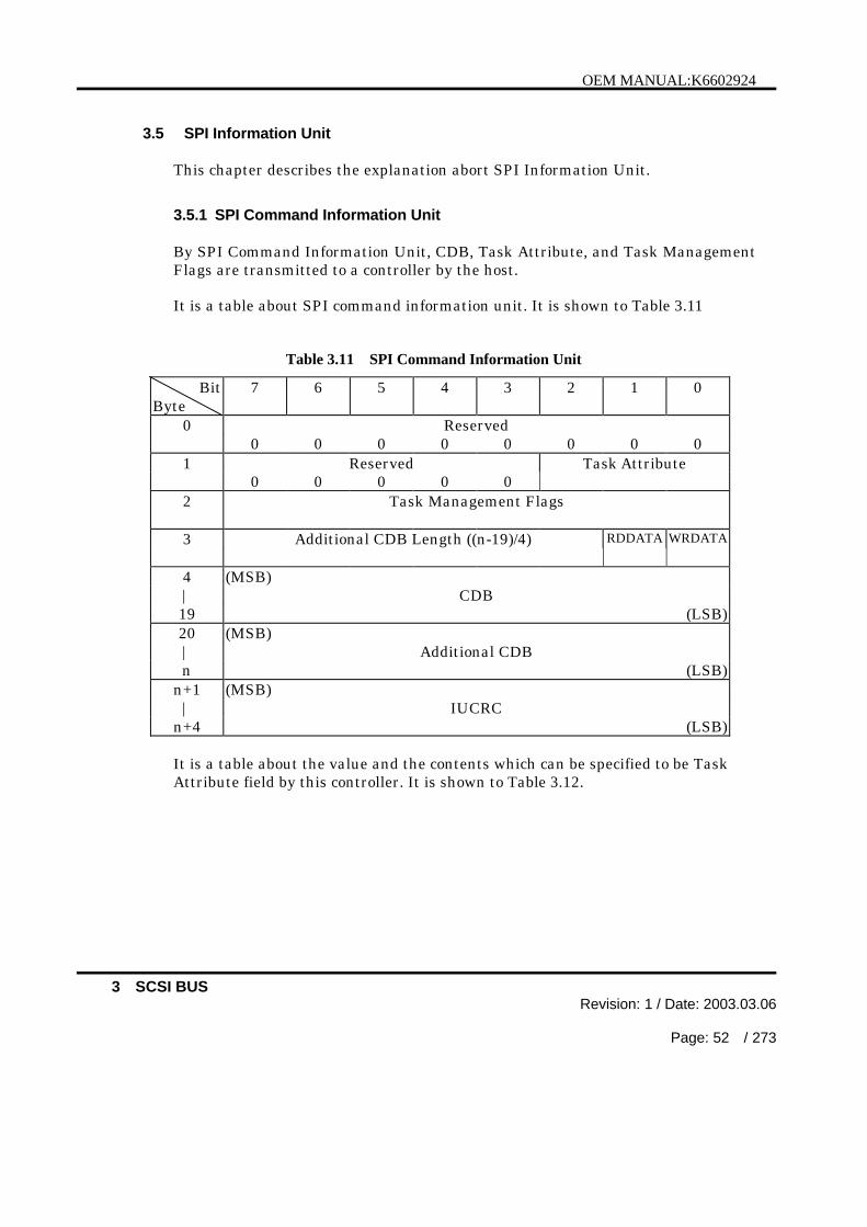
OEM MANUAL:K6602924
3 SCSI BUSRevision: 1 / Date: 2003.03.06
Page: 52 / 273
3.5 SPI Information Unit
This chapter describes the explanation abort SPI Information Unit.
3.5.1 SPI Command Information Unit
By SPI Command Information Unit, CDB, Task Attribute, and Task ManagementFlags are transmitted to a controller by the host.
It is a table about SPI command information unit. It is shown to Table 3.11
Table 3.11 SPI Command Information Unit
BitByte
7 6 5 4 3 2 1 0
0 Reserved0 0 0 0 0 0 0 0
1 Reserved Task Attribute0 0 0 0 0
2 Task Management Flags
3 Additional CDB Length ((n-19)/4) RDDATA WRDATA
4 (MSB)| CDB19 (LSB)20 (MSB)| Additional CDBn (LSB)
n+1 (MSB)| IUCRC
n+4 (LSB)
It is a table about the value and the contents which can be specified to be TaskAttribute field by this controller. It is shown to Table 3.12.

OEM MANUAL:K6602924
3 SCSI BUSRevision: 1 / Date: 2003.03.06
Page: 53 / 273
Table 3.12 Task Attribute
Code Description000b Simple Queue Task001b Head of Queue Task010b Ordered Queue Task011b Reserved100b ACA(Automatic Contingent Allegiance) Task(not support)
101b-111b Reserved
The controller does not support ACA (Automatic Contingent Allegiance).
If a non supported task attribute or task attribute of reserve is specified to be TaskAttribute of SPI Command Information Unit, the controller sets SPI COMMANDINFORMATION UNIT FIELD INVALID as Packetized Failure Code of SPI StatusInformation Unit.
The Task Management Function of current I_T_L_Q Nexus is specified to be theTask Management Flags field.It is a table about the value and the contents which can be specified to be TaskManagement Flags field by this controller. It is shown to Table 3.13.
Table 3.13 Task Management Flags
Code Description00 H Indicates no task management requests for the current task.01 H The task manager shall abort the task as defined in the ABORT
TASK message.02 H The task manager shall abort the task set as defined in the ABORT
TASK SET message.04 H The task manager shall clear the task set as defined in the CLEAR
TASK SET message.08 H The task manager shall perform a logical unit reset of the selected
logical unit as defined in the LOGICAL UNIT RESET message.(nonsupport)
20 H The task manager shall perform a target reset as defined in theTARGET RESET message.
40 H The task manager shall perform a clear ACA as defined in theCLEAR ACA message.(non support)
Others The task manager shall terminate the task with a GOOD status.Thepacketized failure code shall be set to TASK MANAGEMENTFUNCTION NOT SUPPORTED.

OEM MANUAL:K6602924
3 SCSI BUSRevision: 1 / Date: 2003.03.06
Page: 54 / 273
The controller does not support a LOGICAL UNIT RESET message and CLEARACA message.
When specified Task Management Function goes wrong, the controller sets GOODas Status field of SPI Status Information Unit, and sets TASK MANAGEMENTFUNCTION FAILED as a setup and Packetized Failure Code.
The WRDATA(Write Data)bit and RDDATA(Read Data) bit are ignore by thecontroller.
The CDB field contains the actual CDB to be interpreted by the addressed logicalunit. The CDB field and the Task Attribute field is not valid and is ignored if theTask Management Flags field is not zero. Any bytes between the end of a 6 byteCDB, 10 byte CDB, or 12 byte CDB and the end of the CDB field shall be reserved.
The Additional CDB field contains any CDB bytes beyond those contained withinthe standard 16b byte CDB field.
The CDB field, Additional CDB field, and Task Attribute field are not valid and areignore if the Task Management Flags field is not zero.
The contents of the CDB and Additional CDB fields shall be as defined in the SCSIcommand standards.
IUCRC(Information Unit CRC) is specified to be IUCRC field.
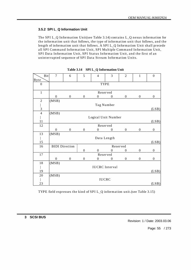
OEM MANUAL:K6602924
3 SCSI BUSRevision: 1 / Date: 2003.03.06
Page: 55 / 273
3.5.2 SPI L_Q Information Unit
The SPI L_Q Information Unit(see Table 3.14) contains L_Q nexus information forthe information unit that follows, the type of information unit that follows, and thelength of information unit that follows. A SPI L_Q Information Unit shall precedeall SPI Command Information Unit, SPI Multiple Command Information Unit,SPI Data Information Unit, SPI Status Information Unit, and the first of anuninterrupted sequence of SPI Data Stream Information Units.
Table 3.14 SPI L_Q Information Unit
BitByte
7 6 5 4 3 2 1 0
0 TYPE
1 Reserved0 0 0 0 0 0 0 0
2 (MSB)| Tag Number3 (LSB)4 (MSB)| Logical Unit Number11 (LSB)12 Reserved
0 0 0 0 0 0 0 013 (MSB)| Data Length15 (LSB)16 BIDI Direction Reserved
0 0 0 0 0 017 Reserved
0 0 0 0 0 0 0 018 (MSB)| IUCRC Interval19 (LSB)20 (MSB)| IUCRC23 (LSB)
TYPE field expresses the kind of SPI L_Q information unit.(see Table 3.15)
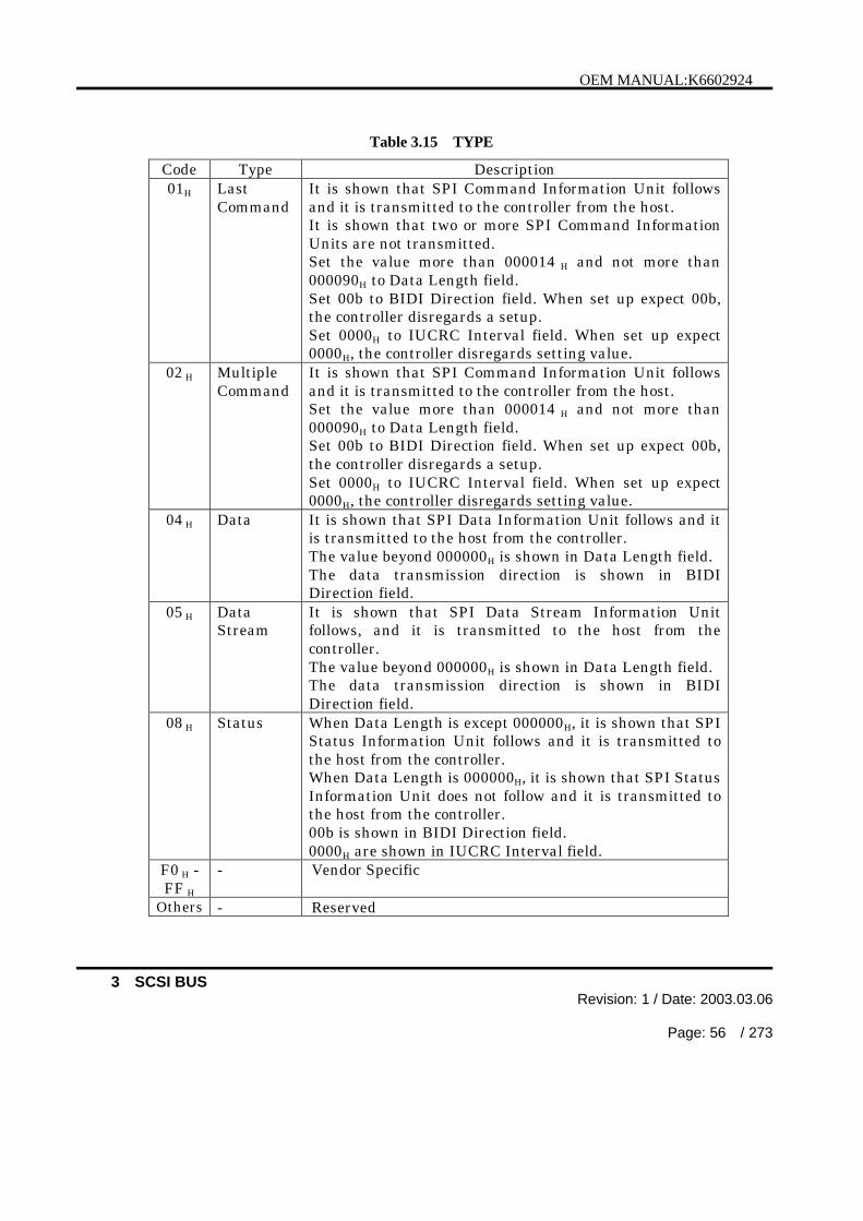
OEM MANUAL:K6602924
3 SCSI BUSRevision: 1 / Date: 2003.03.06
Page: 56 / 273
Table 3.15 TYPE
Code Type Description01H Last
CommandIt is shown that SPI Command Information Unit followsand it is transmitted to the controller from the host.It is shown that two or more SPI Command InformationUnits are not transmitted.Set the value more than 000014 H and not more than000090H to Data Length field.Set 00b to BIDI Direction field. When set up expect 00b,the controller disregards a setup.Set 0000H to IUCRC Interval field. When set up expect0000H, the controller disregards setting value.
02 H MultipleCommand
It is shown that SPI Command Information Unit followsand it is transmitted to the controller from the host.Set the value more than 000014 H and not more than000090H to Data Length field.Set 00b to BIDI Direction field. When set up expect 00b,the controller disregards a setup.Set 0000H to IUCRC Interval field. When set up expect0000H, the controller disregards setting value.
04 H Data It is shown that SPI Data Information Unit follows and itis transmitted to the host from the controller.The value beyond 000000H is shown in Data Length field.The data transmission direction is shown in BIDIDirection field.
05 H DataStream
It is shown that SPI Data Stream Information Unitfollows, and it is transmitted to the host from thecontroller.The value beyond 000000H is shown in Data Length field.The data transmission direction is shown in BIDIDirection field.
08 H Status When Data Length is except 000000H, it is shown that SPIStatus Information Unit follows and it is transmitted tothe host from the controller.When Data Length is 000000H, it is shown that SPI StatusInformation Unit does not follow and it is transmitted tothe host from the controller.00b is shown in BIDI Direction field.0000H are shown in IUCRC Interval field.
F0 H -FF H
- Vendor Specific
Others - Reserved
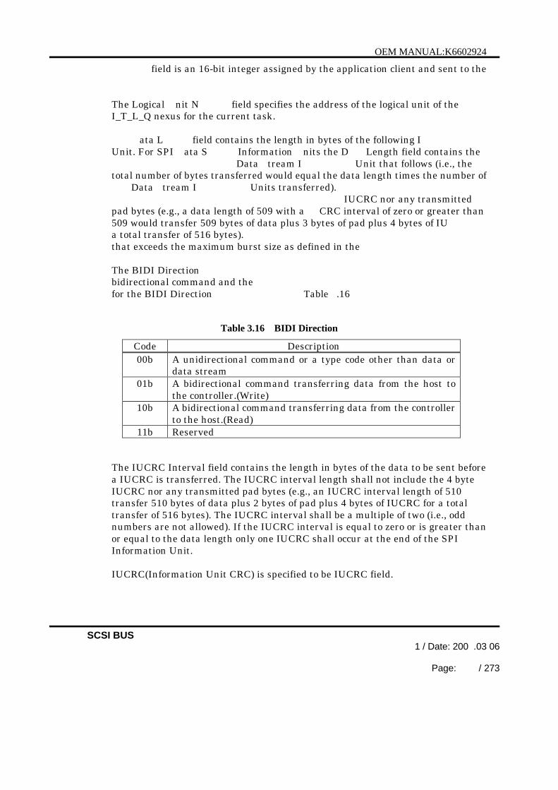
OEM MANUAL:K6602924
SCSI BUS1 / Date: 200 .03 06
Page: / 273
field is an 16-bit integer assigned by the application client and sent to the
The Logical nit N field specifies the address of the logical unit of theI_T_L_Q nexus for the current task.
ata L field contains the length in bytes of the following IUnit. For SPI ata S Information nits the D Length field contains the
Data tream I Unit that follows (i.e., thetotal number of bytes transferred would equal the data length times the number of
Data tream I Units transferred).IUCRC nor any transmitted
pad bytes (e.g., a data length of 509 with a CRC interval of zero or greater than509 would transfer 509 bytes of data plus 3 bytes of pad plus 4 bytes of IUa total transfer of 516 bytes). that exceeds the maximum burst size as defined in the
The BIDI Directionbidirectional command and the for the BIDI Direction Table .16
Table 3.16 BIDI Direction
Code Description00b A unidirectional command or a type code other than data or
data stream01b A bidirectional command transferring data from the host to
the controller.(Write)10b A bidirectional command transferring data from the controller
to the host.(Read)11b Reserved
The IUCRC Interval field contains the length in bytes of the data to be sent beforea IUCRC is transferred. The IUCRC interval length shall not include the 4 byteIUCRC nor any transmitted pad bytes (e.g., an IUCRC interval length of 510transfer 510 bytes of data plus 2 bytes of pad plus 4 bytes of IUCRC for a totaltransfer of 516 bytes). The IUCRC interval shall be a multiple of two (i.e., oddnumbers are not allowed). If the IUCRC interval is equal to zero or is greater thanor equal to the data length only one IUCRC shall occur at the end of the SPIInformation Unit.
IUCRC(Information Unit CRC) is specified to be IUCRC field.

OEM MANUAL:K6602924
3 SCSI BUSRevision: 1 / Date: 2003.03.06
Page: 58 / 273
3.5.3 SPI Data Information Unit
The SPI data information unit (see Table 3.17) contains data.
The detection of a BUS FREE phase following a SPI data information unit by aninitiator shall be equivalent to the initiator receiving a DISCONNECT message.
The detection of a QAS REQUEST message following a SPI data information unitby an initiator shall be equivalent to the initiator receiving a DISCONNECTmessage.
Table 3.17 SPI Data Information Unit
BitByte
7 6 5 4 3 2 1 0
0 (MSB)| Datan (LSB)
n+1 (MSB)| IUCRC
n+4 (LSB)
The Data field may contain any type of information (e.g., parameter lists, modepages, user data, etc.).
IUCRC(Information Unit CRC) is specified to be IUCRC field.
3.5.4 SPI Data Stream Information Unit
The SPI data stream information unit (see Table 3.18) contains data.
All the SPI data stream information units transferred after a SPI L_Q informationunit with a type of data stream shall be the size indicated in the DATA LENGTHfield of the SPI L_Q information unit.
If the data transfer size is not a multiple of the data length, the target shall endthe stream at a data length boundary and shall send a new SPI L_Q with a smallerdata length to finish the data transfer. The new SPI L_Q may or may not be sentduring the current physical connection.

OEM MANUAL:K6602924
3 SCSI BUSRevision: 1 / Date: 2003.03.06
Page: 59 / 273
Table 3.18 SPI Data Stream Information Unit
BitByte
7 6 5 4 3 2 1 0
0 (MSB)| Datan (LSB)
n+1 (MSB)| IUCRC
n+4 (LSB)
The DATA field may contain any type of information (e.g., parameter lists, modepages, user data, etc.).
IUCRC(Information Unit CRC) is specified to be IUCRC field.
3.5.5 SPI Status Information Unit
The SPI status information unit (see Table 3.19) contains the completion status ofthe task indicated by the preceding SPI L_Q information unit. The target shallconsider the SPI status information unit transmission to be successful when thereis no attention condition on the transfer of the information unit.
If a task completes with a GOOD status, a SNSVALID bit of zero, and aRSPVALID bit of zero then the target shall set the DATA LENGTH field in the SPIL_Q Information Unit (see 3.5.2) to zero.

OEM MANUAL:K6602924
3 SCSI BUSRevision: 1 / Date: 2003.03.06
Page: 60 / 273
Table 3.19 SPI Status Information Unit
BitByte
7 6 5 4 3 2 1 0
0 Reserved0 0 0 0 0 0 0 0
1 Reserved0 0 0 0 0 0 0 0
2 Reserved SNS RSP0 0 0 0 0 0 Valid Valid
3 Status
4 (MSB)| Sense Data List Length(n-m)7 (LSB)8 (MSB)| Packetized Failures List Length(m-11)11 (LSB)12 (MSB)| Packetized Failuresm (LSB)
m+1 (MSB)| Sense Datan (LSB)
n+1 (MSB)| IUCRC
n+4 (LSB)
A SNS Valid (Sense Data Valid) bit of zero indicates the sense data list length shallbe ignored and no sense data is provided. A SNS Valid bit of one indicates theSense Data List Length field specifies the number of bytes in the Sense Data field.If the STATUS field contains a CHECK CONDITION status the SNS Valid bitshall be set to one.
If sense data is provided, the SNS Valid bit shall be set to one and the Sense DataList Length field shall specify the number of bytes in the Sense Data field. TheSense Data List Length field shall only contain even lengths greater than zero andshall not be set to a value greater than 252.
If no sense data is provided, the SNS Valid bit shall be set to zero. The host shallignore the Sense Data List Length field and shall assume a length of zero.
If packetized failure data is provided, the RSP Valid (Packetized Failures Valid)bit shall be set to one and the Packetized Failures List Length field shall specify

OEM MANUAL
3 Revision: 1 3. .06
61 / 2
the number of bytes in the Packetized ailures field. The Packetized ailures LLengthstandardization.
If no packetized failure data is provided, the bit shall be set to zero.The initiator shall ignore the P Failures ist L field and shallassume a length of zero.
tatus field contains the status of a task that completes. See STATUS for alist of status codes.
the packetized failures FAILURES field shall contain valid information if the conditions described by the packetized failure code (see Table .20
Table 3 20 Packetized Failure field
Byte7 5 4 2 1
0 Reserved0 0 0 0 0
10 0 0 0 0 0
Reserved0 0 0 0 0
3 Packetized Failure Code
acketized F field is defined in Table .21
Table 3 21 Packetized Failure Code
Description00 NO FAILURE or TASK MANAGEMENT FUNCTION COMPLETE.01 Reserved02 SPI COMMAND INFORMATION UNIT FIELDS INVALID03 Reserved04 TASK MANAGEMENT FUNCTION NOT SUPPORTED05 TASK MANAGEMENT FUNCTION FAILED06 INVALID TYPE CODE RECEIVED IN SPI L_Q INFORMATION
UNITH ILLEGAL REQUEST RECEIVED IN SPI L_Q INFORMATION UNIT
H -FF Reserved

OEM MANUAL:K6602924
4 SCSI COMMANDSRevision: 1 / Date: 2003.03.06
Page: 62 / 273
4 SCSI COMMANDS
The SCSI commands are defined as the data structure viewed through the SCSIinterface.
A single command may transfer one or more logical blocks of data.The controller may disconnect from the SCSI bus while making preparations for datatransfer to make the SCSI bus available to other SCSI devices.
Whenever a command is completed (normally or abnormally), the controller returns thestatus byte to the host computer.
4.1 COMMAND STRUCTURE
A request to the controller is generated by the host computer sending a commanddescriptor block (CDB). For some commands, the request is accompanied by aParameter List that are transferred in the Data Out phase to give a detaileddefinition of the request.
The CDB consists of the operation code, the logical unit number, the commandparameters and the control byte. Its length varies depending on the value of thegroup code in the operation code.
If an invalid parameter is found in the CDB, the controller terminates the commandwithout accessing the disk medium.
In the rest of this section, only the items that are common to the SCSI commands aredescribed. Specifications that are unique to the individual commands are found inChapter 5.
Table 4.1 shows the format of the standard CDB (for 6-byte commands), Table 4.2shows that of the standard CDB (for 10-byte commands) and Table 4.3 shows that ofthe standard CDB (for 12-byte commands).

:K6602924
4 SCSI COMMANDSRevision: / Date: 2003 03.
Page: 63 73
Table .1
BitByte
6 5 3 2 0
0 Operation Code
1 Logical Unit Number Logical Block Address (MSB)
2 Logical Block Address
3 Logical Block Address (LSB)
4 Transfer Length
5 Control Byte
Table 4.2 Standard Command Descriptor Block for 10-byte Commands
BitByte
7 6 5 4 3 2 1 0
0 Operation Code
1 Logical Unit Number Reserved RelAdr
2 Logical Block Address (MSB)
3 Logical Block Address
4 Logical Block Address
5 Logical Block Address (LSB)
6 Reserved
7 Transfer Length (MSB)
8 Transfer Length (LSB)
9 Control Byte

OEM MANUAL
4 Revision: 1 3. .06
64 / 2
Table 4 3 Standard Command Descriptor Block for 12-byte Commands
Byte7 5 4 2 1
0 Operation Code
1 Logical Unit Number Reserved RelAdr
2 Logical Block Address (MSB)
3 Logical Block Address
4 Logical Block Address
5 Logical Block Address (LSB)
6 Transfer Length (MSB)
7 Transfer Length
8 Transfer Length
9 Transfer Length (LSB)
10 Reserved
11 Control Byte
4.1.1 OPERATION CODE
Table 4.4 shows the format of the operation code.
Table 4.4 Operation Code
BitByte
7 6 5 4 3 2 1 0
0 Group Code Command Code
The Operation Code consists of the group code and the command code.

:K6602924
4 SCSI COMMANDSRevision: / Date: 2003 03.
Page: 65 73
This controller supports group 0 (6-byte commands) and group 1 and 2 (10-byte
receives an unsupported or undefined command, it creates the CHECKCONDITION status with ILLEGAL REQUEST sense key. See Chapter 5 for the
4.1.2
The Logical Unit Number (LUN) identifies a logical unit attached to the controller.The controller supports a LUN of 0.
(except the INQUIRY and REQUEST SENSE commands) with a CHECK
controller ignores this field when it received an IDENTIFY message.
RELATIVE ADDRESS
4.1.4
The Logical Block Address on a logical unit begins with block 0 and is contiguousup to the last logical block on that logical unit.
5 CDBs contain a 32-bit Logical Block Address area.
If a logical block address beyond the logical block address (this address is reported
block on a logical unit is specified, the controller creates the CHECK CONDITIONstatus with ILLEGAL REQUEST sense key.
(explained later) to access a block beyond the last block on the logical unit, thecontroller specifies the address as an invalid logical block address and creates the
The number of data bytes per logical block is reported to the host computerthrough the READ CAPACITY or MODE SENSE command.

OEM MANUAL:K6602924
4 SCSI COMMANDSRevision: 1 / Date: 2003.03.06
Page: 66 / 273
4.1.5 TRANSFER LENGTH
The Transfer Length specifies the amount of data to be transferred (normally inlogical blocks).
In some commands, the transfer length represents the number of requested bytesas explained in their command descriptions.In such cases, this field is referred to as the byte transfer length field.
Commands (6-byte commands) that allocates one byte to the transfer length fieldcan transfer a maximum of 256 blocks of data. Transfer lengths of 1 to 255represent the number of blocks to be transferred and transfer length of 0represents 256 blocks.
Commands (10-byte commands) that allocates two bytes to the transfer lengthfield can transfer a maximum of 65, 535 blocks of data. A transfer length of 0indicates that no block is to be transferred.Transfer lengths of 1 to 65, 535 represent the number of blocks to be transferred.
Commands (12-byte commands) that allocates four bytes to the transfer lengthfield can transfer a maximum of 4,294,967,295 blocks of data. A transfer lengthof 0 indicates that no block is to be transferred.Transfer lengths of 1 to 4,294,967,295 represent the number of blocks to betransferred.
The transfer length of commands that transfer a parameter list to the controller iscalled the parameter list length. The parameter list length is used to specify thenumber of bytes to be transferred during the Data Out phase.
The transfer length of commands that return sense data to the host computer (e.g.,REQUEST SENSE, INQUIRY, and MODE SENSE commands) is called theAllocation Length. The allocation length is used to specify the number of bytesthat are allocated by the host computer for the data to be transferred.
The controller terminates the Data In phase when the number of bytes specified inthe Allocation Length field have been transferred or when all available sense datahave been transferred to the host computer, whichever is less.
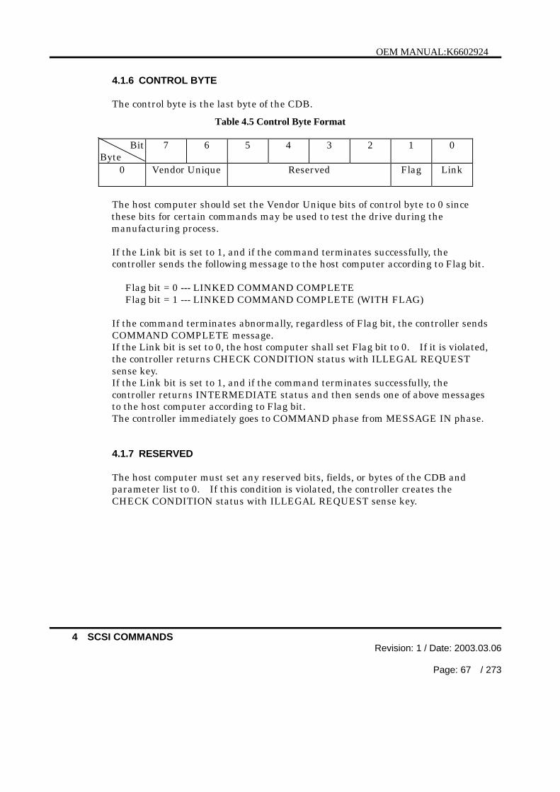
OEM MANUAL:K6602924
4 SCSI COMMANDSRevision: 1 / Date: 2003.03.06
Page: 67 / 273
4.1.6 CONTROL BYTE
The control byte is the last byte of the CDB.
Table 4.5 Control Byte Format
BitByte
7 6 5 4 3 2 1 0
0 Vendor Unique Reserved Flag Link
The host computer should set the Vendor Unique bits of control byte to 0 sincethese bits for certain commands may be used to test the drive during themanufacturing process.
If the Link bit is set to 1, and if the command terminates successfully, thecontroller sends the following message to the host computer according to Flag bit.
Flag bit = 0 --- LINKED COMMAND COMPLETEFlag bit = 1 --- LINKED COMMAND COMPLETE (WITH FLAG)
If the command terminates abnormally, regardless of Flag bit, the controller sendsCOMMAND COMPLETE message.If the Link bit is set to 0, the host computer shall set Flag bit to 0. If it is violated,the controller returns CHECK CONDITION status with ILLEGAL REQUESTsense key.If the Link bit is set to 1, and if the command terminates successfully, thecontroller returns INTERMEDIATE status and then sends one of above messagesto the host computer according to Flag bit.The controller immediately goes to COMMAND phase from MESSAGE IN phase.
4.1.7 RESERVED
The host computer must set any reserved bits, fields, or bytes of the CDB andparameter list to 0. If this condition is violated, the controller creates theCHECK CONDITION status with ILLEGAL REQUEST sense key.
:K6602924
4 SCSI COMMANDSRevision: / Date: 2003 03.
Page: 68 73
4.1.8 VENDOR UNIQUE
The host computer must set any vendor unique bits, fields, or bytes of the CDB
(normally to 0). The controller checks the vendor unique bits, fields, or bytes. Ifthis condition is violated, the controller will create the CHECK CONDITION

OEM MANUAL:K6602924
5 COMMAND DESCRIPTIONSRevision: 1 / Date: 2003.03.06
Page: 69 / 273
5 COMMAND DESCRIPTIONS
5.1 FORMAT UNIT:(04H)
BitByte
7 6 5 4 3 2 1 0
0 Operation Code (04H)0 0 0 0 0 1 0 0
1 Logical Unit Number FmtData CmpLst Defect List Format
2 Certification Pattern
3 Interleave (MSB)
4 Interleave (LSB)
5 Vendor Unique Reserved Flag Link0 0 0 0 0 0
The FORMAT UNIT command formats the medium so that all of the addressabledata blocks can be accessed by the host. Any existing data on the medium is lostafter the FORMAT UNIT command is initiated by the controller.
The controller formats the media in accordance with the current value of MODESELECT parameter (see 5.5 MODE SELECT) established and the media defectmanagement schemes specified from the host computer by this command.
It is recommended that the MODE SELECT parameters should be set properly priorto the issuance of FORMAT UNIT command.A FORMAT UNIT command must be sent if the block length or the number ofalternate spare areas are changed.
If FORMAT UNIT command is completed abnormally after formatting is started, thecommand accesses to medium after FORMAT UNIT command is terminated withCHECK CONDITION status, then the controller sets the sense key to NOT READYwith the additional sense code of FORMAT COMMAND FAILED.
There are four defect management schemes, namely, P, C, D and G.
< P = Primary Defect List >This list refers to the list of defects that are considered as permanent flaws.This list is recorded in a specific location on the device by the manufacturer ofthe device.
FORMAT UNIT:(04h)

OEM MANUAL:K6602924
5 COMMAND DESCRIPTIONSRevision: 1 / Date: 2003.03.06
Page: 70 / 273
< C = Target Certification >Includes defects that are detected by the controller during an optional verifyprocess executed during the FORMAT UNIT command. The controllerincludes the list into the G list and records it in a specific location on the device.
< D = Data Defect List >This list is supplied to the controller by the host computer in the Data Out phaseof the FORMAT UNIT or REASSIGN BLOCKS command (see 5.15, “ReassignBlocks”). The controller includes the list into the G list and records it in aspecific location on the device.The host needs to specify the defect of user area within the limits.
< G = Grown Defect List>This list includes the defects from the C and D lists that are added as the resultof the normal termination of the proceeding FORMAT UNIT or REASSIGNBLOCKS command. This list is distinguished from the P list and its defectsare classified as grown after the manufacture of the medium.
The FmtData (Format Data) bit = 1 indicates that the defect list header and defectdata (defect descriptors) are transferred from the host computer during the Data Outphase of the command.The format of the defect data is determined by the Defect List Format field in bits 0-2.The FmtData bit = 0 indicates that the Data Out phase must not occur, that is,neither defect list header nor defect data must be supplied from the host computer.The controller executes the formatting with the default mode of the controller andCmpLst must be set to 0.
Note : The default mode is DPRY, DCRT, STPF, IP and DSP set to 0. (These functionare explained in the Defect List Header section.)
The CmpLst (Complete List) bit = 1 indicates that the data supplied by the hostcomputer during the Data Out phase of this command is the complete list of knowndefects. The controller deletes the old G list and creates a new list.The CmpLst bit = 0 indicates that the data supplied by the host computer duringthe Data Out phase of the command is to be added to the existing defect data.
Note : If FmtData bit is set to 0, CmpLst bit is ignored. The controller uses the default value (CmpLst bit off).
The Defect List format field specifies additional information related to the defect list(see Table 5.1 for further information).
The Certification Pattern field specifies the data pattern to be written in data blocks.
FORMAT UNIT:(04h)

OEM MANUAL:K6602924
5 COMMAND DESCRIPTIONSRevision: 1 / Date: 2003.03.06
Page: 71 / 273
The Interleave field requests that the logical blocks are related in a specific mannerto physical blocks to facilitate speed matching between the host bus data transferrate and the block data transfer rate of the device.This controller supports the Interleave value one only but ignores the Interleave field.
The host computer can specify the format for the defect management schemes anddefect list according to the definition of CDB byte 1, bits 0-4, as summarized in Table5.1.
Table 5.1 Format Unit Command Variations
4FmtData
3CmpLst
2 1 0Defect List Format
DefectList
Length
DefectManagement
DefectList
Format0 X X X X - P + C + G -1 0 0 X X =0 (P) + (C) + G -1 1 0 X X =0 (P) + (C) -1 0 0 X X >0 (P) + (C) + D + G Block1 1 0 X X >0 (P) + (C) + D (Note 3)1 0 1 0 0 >0 or =0 (P) + (C) + D + G Byte from1 1 1 0 0 >0 or =0 (P) + (C) + D index format1 0 1 0 1 >0 or =0 (P) + (C) + D + G Physical1 1 1 0 1 >0 or =0 (P) + (C) + D sectorNote 1 : X denotes a don't care condition.Note 2 : Defect management schemes enclosed in parentheses depend on the
defect list header specification.Note 3 : When CmpLst bit = 0, the defect list data needs to be transferred in the
format of logical block address.when CmpLst bit = 1. the defect list data needs to be transferred in theformat of physical block address. Physical block address is defined assequential number, starting from zero, of physical sectors which locatein the user cylinder area.
The controller allocates alternate sectors for defect blocks according to the specifieddefect management scheme.
The defect list comprises the defect list header shown Table 5.2 followed by defectdescriptors (see Table 5.3, Table 5.4 and Table 5.5).
FORMAT UNIT:(04h)

OEM MANUAL:K6602924
5 COMMAND DESCRIPTIONSRevision: 1 / Date: 2003.03.06
Page: 72 / 273
Table 5.2 Defect List Header
BitByte
7 6 5 4 3 2 1 0
0 Reserved0 0 0 0 0 0 0 0
1 FOV DPRY DCRT STPF IP DSP Immed VU0
2 Defect List Length (MSB)
3 Defect List Length (LSB)
The host computer can control the following format processing by defining byte 1,bits 2-7 of the defect list header.
Bit 7 : The FOV (Format Options Valid) bit, when set to 0, specifies that the defaultvalues of the controller are used for the functions defined in bits 2-6.The default values of the controller are all zeros for bits 2 through 6. Whenthe FOV bit is set to 0, the host computer must set bits 2 through 6 to allzeros.If this conditions is violated, the controller creates the CHECK CONDITIONstatus with ILLEGAL REQUEST sense key.When the FOV bit is specified to 1, the controller is to take action asspecified by the host computer in bits 2-6.
Bit 6 : The DPRY (Disable Primary) bit, when set to 0, specifies that the controlleris to format the medium using the primary defect list. When this bit is set to1, the controller does not use the primary defect list.
Bit 5 : The DCRT (Disable Certification) bit, when set to 0, specifies that thecontroller executes target certification (verify) processing during formatting.When this bit is set to 1, the controller suppresses target certificationprocessing.
FORMAT UNIT:(04h)

OEM MANUAL:K6602924
5 COMMAND DESCRIPTIONSRevision: 1 / Date: 2003.03.06
Page: 73 / 273
Bit 4 : The STPF (Stop Format) bit, when set to 0, specifies that the controller is toexecute the formatting even if an unrecoverable error occurs while accessingeither list of defects P or G recorded on the device. In this case, if no erroroccurred except during the access to the defect list, the controller creates theCHECK CONDITION status with RECOVERED ERROR sense key aftercompletion of the format process.When the STPF bit is set to 1 and an unrecoverable error occurs during theaccess to the defect list, the controller stops the format process andterminates the command with a CHECK CONDITION status and set thesense key to “MEDIUM ERROR”.
Bit 3 : The IP (Initialization Pattern) bit of 1 indicates that initialization patterndescriptor is included in the Format Unit parameter list immediatelyfollowing the defect list header and is used to initialize the data blocks. AnIP bit of 0 indicates that an initialization pattern descriptor is not includedand the controller shall use the certification pattern in the commanddescriptor block for the data block initialization.
Bit 2 : The DSP (Disable Saving Parameters) bit, when set to 1, specifies that thecontroller shall not save the MODE SELECT savable parameters to non-volatile memory during the format operation.A DSP bit of 0 specifies that the controller shall save all the MODE SELECTsavable parameters for all initiators to non-volatile memory after the formatprocess completed normally.
Bit 1 : If the Immed (Immediate) bit is set to 0, a status is not returned until theactual completion of the command.If the Immed (Immediate) bit is set to 1, a status is returned as soon as thecommand descriptor block has been validated, and the entire defect list hasbeen transferred.
The defect list length specifies the total length in bytes of the subsequent defectdescriptors following either the defect list header (if IP bit = 0) or the initializationpattern descriptor. This value may be zero. In this case, no defect descriptor istransferred from the host computer.
The defect list length value must be four times the number of defect descriptors forthe block format (Table 5.3) and eight times the number of defect descriptors for thebyte from index format (Table 5.4) or the physical sector format (Table 5.5).
FORMAT UNIT:(04h)

OEM MANUAL:K6602924
5 COMMAND DESCRIPTIONSRevision: 1 / Date: 2003.03.06
Page: 74 / 273
When no 4-byte header is transferred or when an invalid defect list length is specified,the controller creates the CHECK CONDITION status with ILLEGAL REQUESTsense key.
Table 5.3 Defect List --- Block Format
Byte Defect Descriptor (s)0 Defect Block Address (MSB)1 Defect Block Address2 Defect Block Address3 Defect Block Address (LSB)
Each defect descriptor specifies the 4-byte defect block address of the blockcontaining a defect.
If a block address exceeding the maximum address allowed for the drive is specified,the controller creates the CHECK CONDITION status with ILLEGAL REQUESTsense key.
When the CmpLst bit (CDB byte 1, bit 3) is set to 0, the defect block address specifiesthe logical block address related to block length of the block that is currently beingformatted.When the CmpLst bit is set to 1, the defect block address specifies the physical blockaddress related to the new block length.
Table 5.4 Defect List --- Byte from Index Format
Byte Defect Descriptor (s)0 Cylinder Number of Defect (MSB)1 Cylinder Number of Defect2 Cylinder Number of Defect (LSB)3 Head Number of Defect4 Defect Bytes from Index (MSB)5 Defect Bytes from Index6 Defect Bytes from Index7 Defect Bytes from Index (LSB)
Each defect descriptor specifies the Cylinder Number, Head Number and Bytes fromIndex. The host computer must send the defect descriptors in the ascending order ofaddress. The most significant address is the Cylinder Number and the least one isthe Bytes from Index.It is not possible to specify the value of FFFFFFFFH (as a bad track) to the DefectBytes from Index field.
FORMAT UNIT:(04h)

OEM MANUAL:K6602924
5 COMMAND DESCRIPTIONSRevision: 1 / Date: 2003.03.06
Page: 75 / 273
If the defect location is identified as invalid or the defect descriptors are not in theascending order of address, the controller returns CHECK CONDITION status withILLEGAL REQUEST sense key.
Note 1 : When the G list is read by the READ DEFECT DATA command, theobtained Defect Bytes from Index value appears with respect to only thefirst defect in the same sector.
Table 5.5 Defect List --- Physical Sector Format
Byte Defect Descriptor (s)0 Cylinder Number of Defect (MSB)1 Cylinder Number of Defect2 Cylinder Number of Defect (LSB)3 Head Number of Defect4 Defect Sector Number (MSB)5 Defect Sector Number6 Defect Sector Number7 Defect Sector Number (LSB)
Each defect descriptor specifies the Cylinder Number, Head Number and SectorNumber. The host computer must send the defect descriptors in the ascending orderof address. The most significant address is the Cylinder Number and the least oneis the Sector Number field.
It is not possible to specify the value of FFFFFFFFH (as a bad track) to the DefectSector Number field.
If the defect location is identified as invalid or the defect descriptors are not in theascending order of address, the controller returns CHECK CONDITION status withILLEGAL REQUEST sense key.
Table 5.6 Initialization Pattern Descriptor
BitByte
7 6 5 4 3 2 1 0
0 IP Modifier Reserved0 0 0 0 0 0
1 Pattern Type
2 Initialization Pattern Length (MSB)
3 Initialization Pattern Length (LSB)
(cont’d)
FORMAT UNIT:(04h)
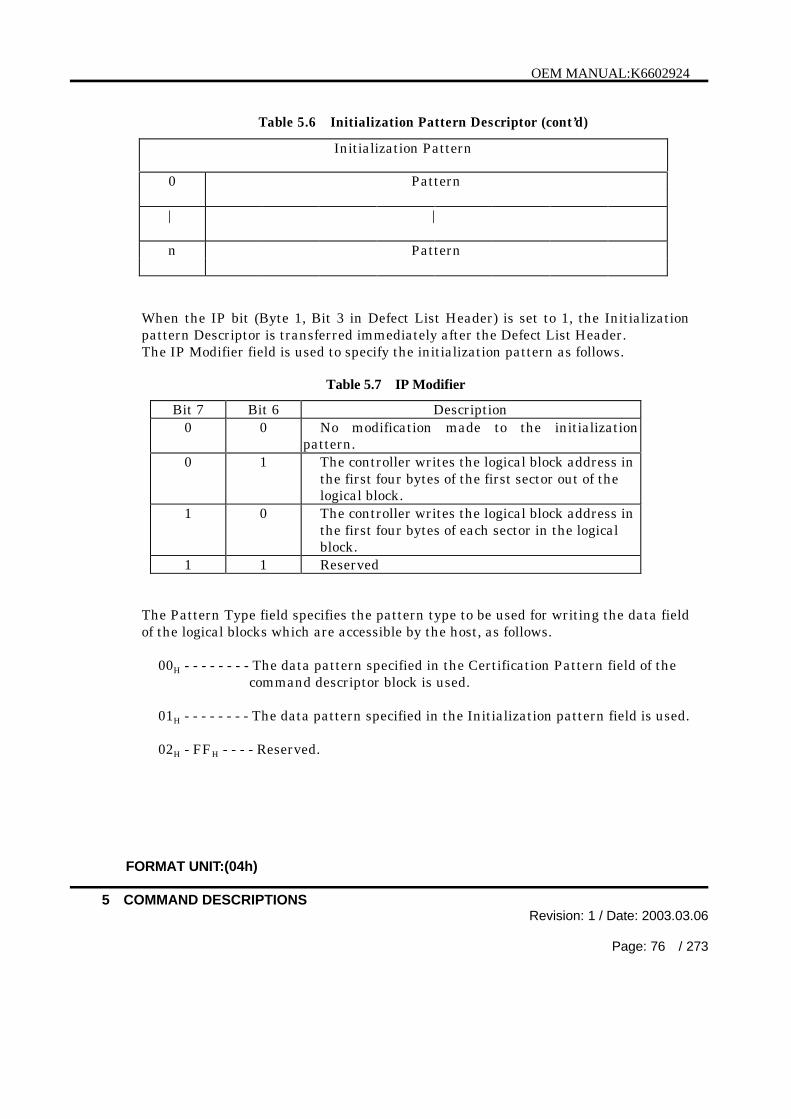
OEM MANUAL:K6602924
5 COMMAND DESCRIPTIONSRevision: 1 / Date: 2003.03.06
Page: 76 / 273
Table 5.6 Initialization Pattern Descriptor (cont’d)
Initialization Pattern
0 Pattern
| |
n Pattern
When the IP bit (Byte 1, Bit 3 in Defect List Header) is set to 1, the Initializationpattern Descriptor is transferred immediately after the Defect List Header.The IP Modifier field is used to specify the initialization pattern as follows.
Table 5.7 IP Modifier
Bit 7 Bit 6 Description0 0 No modification made to the initialization
pattern.0 1 The controller writes the logical block address in
the first four bytes of the first sector out of thelogical block.
1 0 The controller writes the logical block address inthe first four bytes of each sector in the logicalblock.
1 1 Reserved
The Pattern Type field specifies the pattern type to be used for writing the data fieldof the logical blocks which are accessible by the host, as follows.
00H - - - - - - - - The data pattern specified in the Certification Pattern field of the command descriptor block is used.
01H - - - - - - - - The data pattern specified in the Initialization pattern field is used.
02H - FFH - - - - Reserved.
FORMAT UNIT:(04h)

OEM MANUAL:K6602924
5 COMMAND DESCRIPTIONSRevision: 1 / Date: 2003.03.06
Page: 77 / 273
The Initialization pattern Length field specifies the following Initialization Patternlength in bytes. The available value to specifies is n (= 0 to bytes/sector).
00H - - - - - - - - The data pattern specified the Certification Pattern field of the command descriptor block is used.
n H - - - - - - - - Specifying the pattern length that follows.
The Pattern field specifies the writing data pattern in the data field. This fieldcontains the data bytes and it is used repeatedly for the writing.
FORMAT UNIT:(04h)

OEM MANUAL:K6602924
5 COMMAND DESCRIPTIONSRevision: 1 / Date: 2003.03.06
Page: 78 / 273
5.2 INQUIRY:(12H)
BitByte
7 6 5 4 3 2 1 0
0 Operation Code (12H)0 0 0 1 0 0 1 0
1 Logical Unit Number Reserved EVPD0 0 0 0
2 Page Code
3 Reserved0 0 0 0 0 0 0 0
4 Allocation Length
5 Vendor Unique Reserved Flag Link0 0 0 0 0 0
The INQUIRY command transfers the parameter information regarding thecontroller to the host computer.
The EVPD (Enable Vital Product Data) bit of 0 indicates that Standard Inquiry Datais transferred from the controller to the host computer. In this case, the Page Codefield must be set to 00H. Otherwise, the controller reports the CHECK CONDITIONwith ILLEGAL REQUEST sense key.
The EVPD bit of 1 indicates that the controller transfers Vital Product Data asspecified in the Page Code field.The Page Code specifies a page of Vital Product Data to be transferred to the hostcomputer. Supported Pages of Vital Product Data are as follows :
Page Code Description
00H Supported Vital Product Data80H Unit Serial umber81H Implemented Operating Definition83H Device IdentificationC0H Jumper Information
When any page code other than above is specified, the controller returns the CHECKCONDITION with ILLEGAL REQUEST sense key.
The allocation length specifies the number of bytes that are allocated by the hostcomputer for the data to be transferred.
INQUIRY:(12h)

OEM MANUAL:K6602924
5 COMMAND DESCRIPTIONSRevision: 1 / Date: 2003.03.06
Page: 79 / 273
No data is transferred if the Allocation Length is set to 0. This condition, however,is not considered as an error. Other allocation length values specify the maximumnumber of bytes to be transferred. The controller terminates the Data In phasewhen the number of bytes specified in the Allocation Length field have beentransferred or when all available inquiry data have been transferred to the hostcomputer, whichever is less.
The controller reports the CHECK CONDITION status only when it cannot transferthe requested inquiry data. The controller does not report the CHECKCONDITION status for the INQUIRY command even if the UNIT ATTENTIONstatus is held pending.And the Unit Attention status is not cleared by INQUIRY command.
The Standard Inquiry Data is shown in Table 5.8 and the Vital Product Data areshown in Table 5.10 (Supported Vital Product Data) and Table 5.11 (Unit SerialNumber).
Table 5.8 Standard Inquiry Data
BitByte
7 6 5 4 3 2 1 0
0 Peripheral Qualifier Peripheral Device Type
1 RMB Device Type Modifier0 0 0 0 0 0 0 0
2 ISO Version ECMA Version ANSI Version0 0 0 0 0 0 1 1
3 AENC Trm IOP Reserved Response Data Format0 0 0 0 0 0 1 0
4 Additional Length (6BH)0 1 1 0 1 0 1 1
5 Reserved0 0 0 0 0 0 0 0
6 Reserved Addr160 0 0 0 0 0 0
7 RelAdr WBus32 Wbus16 SYNC Linked TranDis CmdQue SftRe0 0 1 1 1 1 0
8-15 Vendor Identification (in ASCII)“HITACHI€”
16-31 Product Identification (in ASCII)
32-35 Product Revision Level (in ASCII)
(cont’d)
INQUIRY:(12h)

OEM MANUAL:K6602924
5 COMMAND DESCRIPTIONSRevision: 1 / Date: 2003.03.06
Page: 80 / 273
Table 5.8 Standard Inquiry Data (cont’d)
Product Information
36-43 Product Serial Number
44-51 Reserved0 0 0 0 0 0 0 0
Drive Jumper Information
52 ID Jumper
53 Vendor Unique Auto Delay VendorStart Start Unique
54 Vendor Unique
55 Vendor Unique WriteProtect
56 Reserved Clocking QAS IUS0 0 0 0 1 1
57-95 Reserved0 0 0 0 0 0 0 0
96-143 Copyright (in ASCII)“Copyright (C) 2002 Hitachi All right reserved”
Note : € denotes a space character (code 20H).
The Standard Inquiry Data (Table 5.8) consists of a 5-byte header, followed by 139bytes of additional parameters.
When the LUN is 0, the Peripheral Qualifier field is loaded with code 0H andindicates that the specified device type is currently connected.
The Peripheral Device Type field is loaded with code 0H and identifies a direct accessdevice. If LUN of 1 or more is specified, it is loaded with code 7FH (Qualifier = 3H,Device Type = 1FH), indicating that specified logical unit is not present (Logical Unitnot Present).
The RMB (Removable) bit is always set to 0 and indicates that the medium cannot beremoved.
The Device Type Modifier field is loaded with 0H and identifies the controller does notuse this field.
INQUIRY:(12h)

OEM MANUAL:K6602924
5 COMMAND DESCRIPTIONSRevision: 1 / Date: 2003.03.06
Page: 81 / 273
The ISO Version (International Standard Organization Version) field is loaded withcode 0H and indicates that the controller does not conform with the ISO versionspecification.
The ECMA Version (European Computer Manufacture Association Version) field isloaded with code 0H and indicates that the controller does not conform with theECMA Version specification.
The ANSI Version field is loaded with code 3H and indicates that the controllerconforms with the SCSI-2 version.
The AENC (Asynchronous Event Notification Capability) bit is set to 0 and indicatesthat the controller does not support the asynchronous event notification function.
The Trm IOP (Terminate I/O Process) bit is set to 0 and indicates that the controllerdoes not support the TERMINATE I/O PROCESS message.
The Response Data Format field is loaded with code 2H and indicates that thecontroller conforms with the ANSI SCSI-2 specifications.
The Additional Length field is loaded with code 6BH and indicates that the additionalparameters is consisted of 107 bytes. This field holds the same value, irrespective ofthe allocation length stored in the CDB.
The Addr16(Wide SCSI Address 16) bit of 0 indicates that the controller does notsupport the 16-bit wide SCSI address. The Addr16 bit of 1 indicates that thecontroller supports the 16-bit wide SCSI address.
The RelAdr (Relative Address) bit is set to 0 and indicates that the controller does notsupport the relative address capability.
The WBus 32 (Wide Bus 32) bit is set to 0 and indicates that the controller does notsupport the 32 bits width data transfer.
The WBus 16 (Wide Bus 16) bit of 0 indicates that the controller does not support the16 bits width data transfer. The WBus 16 bit of 1 indicates that the controllersupports the 16 bits width data transfer.
The Sync (Synchronous Transfer) bit is set to 1 and indicates that the controllersupports the synchronous data transfer.
The Linked (Linked Command ) bit is set to 1 and indicates that the controllersupports the linked command capability.
INQUIRY:(12h)

OEM MANUAL:K6602924
5 COMMAND DESCRIPTIONSRevision: 1 / Date: 2003.03.06
Page: 82 / 273
The TranDis (Transfer Disable) bit of 0 indicates that the controller does not supportthe CONTINUE I/O PROCESS and TARGET TRANSFER DISABLE message. TheTranDis bit of 1 indicates that the controller supports the CONTINUE I/O PROCESSand TARGET TRANSFER DISABLE message.
The CmdQue bit of 1 indicates that the controller supports the tagged commandqueuing.
The SftRe (Soft Reset) bit is set to 0 and indicates that the controller only uses theHard Reset.
The vendor identification field contains ''HITACHI'' in ASCII code.The product identification field contains the product name in ASCII code .The Product Revision Level field contains the revision number of the controllerfirmware in ASCII code. When the drive is not ready state, it indicates only theROM program revision, while the drive is ready it indicates the ROM and RAMprogram revision.
< Drive Jumper Information fields >The Drive Jumper Information fields indicate the jumper pins installed on the drivePCB.Refer to the Product Specification for the specification of the jumpers.
< Product Information fields >The Product Serial Number field indicates the drive serial number with 8 digits.
The Clocking field indicates shall not apply to asynchronous transfers and is definedin Table 5.9.
Table 5.9 Clocking
Code Description00b Indicates the controller supports only ST(Single
Transition)01b Indicates the controller supports only DT(Double
Transition)10b Reserved11b Indicates the controller supports ST and DT
The QAS (Quick Arbitrate Supported) bit is set to 1 and indicates that the controllerdoes support the Quick Arbitrate.
The IUS (Information Unit Supported) bit is set 1 and indicates that the controllerdoes support the Information Unit.
INQUIRY:(12h)

OEM MANUAL:K6602924
5 COMMAND DESCRIPTIONSRevision: 1 / Date: 2003.03.06
Page: 83 / 273
The Copyright field contains ''Copyright (C) 2002 Hitachi All right reserved'' in ASCIIcode.
Note : The ASCII data fields are loaded with data starting at their first byte position.Any remaining byte positions are padded with space characters (code 20H).
[ Page Code:00H(EVPD=1) ]
Table 5.10 Supported Vital Product Data
BitByte
7 6 5 4 3 2 1 0
0 Peripheral Qualifier Peripheral Device Type
1 Page Code(00H)0 0 0 0 0 0 0 0
2 Reserved0 0 0 0 0 0 0 0
3 Page Length(06H)0 0 0 0 0 1 1 0
Supported Page List
4 00H
5 80H
6 81H
7 83H
8 C0H
9 Reserved (00H)
The Peripheral Qualifier and Peripheral Device Type are returned as described in theexplanation following the Table 5.8 (Standard Inquiry Data).
The Page Code of 00H indicates that this is the Supported Vital Product Data page.
The Page Length indicates the data length in bytes of Supported Page List.
The Supported Page List indicates the pages supported by the controller in theascending order of their codes.
INQUIRY:(12h)

OEM MANUAL:K6602924
5 COMMAND DESCRIPTIONSRevision: 1 / Date: 2003.03.06
Page: 84 / 273
[ Page Code:80H(EVPD=1) ]
Table 5.11 Unit Serial Number
BitByte
7 6 5 4 3 2 1 0
0 Peripheral Qualifier Peripheral Device Type
1 Page Code (80H)1 0 0 0 0 0 0 0
2 Reserved0 0 0 0 0 0 0 0
3 Page Length (14H)0 0 0 1 0 1 0 0
4to Product Serial Number1112to Card Serial Number23
The Peripheral Qualifier and Peripheral Device Type are returned as described in theexplanation following the Table 5.8 (Standard Inquiry Data).
The Page Code of 80H indicates that this page indicates the unit serial number.
The Page Length indicates the data length in bytes of Product Serial Number(8bytes) and Card Serial Number (12 bytes).
The Product Serial Number indicates the drive serial number with 8 digits.
The Card Serial Number indicates the card serial number with 12 digits.
INQUIRY:(12h)

OEM MANUAL:K6602924
5 COMMAND DESCRIPTIONSRevision: 1 / Date: 2003.03.06
Page: 85 / 273
[ Page Code:81H(EVPD=1) ]
Table 5.12 Implemented Operating Definition Page
BitByte
7 6 5 4 3 2 1 0
0 Peripheral Qualifier Peripheral Device Type
1 Page Code (81H)1 0 0 0 0 0 0 1
2 Reserved0 0 0 0 0 0 0 0
3 Page Length (04H)0 0 0 0 0 1 0 0
4 RSV0
Current Operating Definition
5 SavImp1
Default Operating Definition
Supported Operating Definition List
6 SavImp1 01H
7 SavImp1
03H
The Peripheral Qualifier and Peripheral Device Type are returned as described in theexplanation following the Table 5.8 (Standard Inquiry Data).
The Page Code of 81H indicates that this page indicates the implemented operatingdefinition page.
The Page Length indicates the data length of the following operating definition.
The SavImp (Associated Save Implemented) bit of 0 indicates that the correspondingoperating definition parameter cannot be saved.
The SavImp bit of 1 indicates that the corresponding operating definition parametercan be saved.
The Current Operating Definition field indicates the present operating definition thecontroller uses.The Default Operating Definition field indicates the default operating definition thecontroller uses.The Supported Operating Definition List field indicates the operating definition thecontroller supports.
INQUIRY:(12h)

OEM MANUAL:K6602924
5 COMMAND DESCRIPTIONSRevision: 1 / Date: 2003.03.06
Page: 86 / 273
Each operating definition is defined in Table 5.13.The host computer , however , cannot change the operating definition since thiscontroller does not support CHANGE DEFINITION command.
Table 5.13 Operating Definition
Operating definition value
Operating definition
00H
01H
02H
03H
04H
CurrentSCSI-1
CCSSCSI-2SCSI-3
05H - 7FH Reserved
[ Page Code:83H(EVPD=1) ]
Table 5.14 Device Identification Page
BitByte
7 6 5 4 3 2 1 0
0 Peripheral Qualifier Peripheral Device Type
1 Page Code (83H)1 0 0 0 0 0 1 1
2 Reserved0 0 0 0 0 0 0 0
3 Page Length (24 H)0 0 1 0 0 1 0 0
Identification Descriptor List
4 Reserved Code Set0 0 0 0 0 0 1 0
5 Reserved Association Identifier Type0 0 0 0 0 0 0 1
6 Reserved0 0 0 0 0 0 0 0
7 Identifier Length (20 H)0 0 1 0 0 0 0 0
8 - 15 Vendor Identification (in ASCII)“HITACHI€”
16 - 31 Product Identification (in ASCII)
32 - 39 Product Serial Number
INQUIRY:(12h)

OEM MANUAL:K6602924
5 COMMAND DESCRIPTIONSRevision: 1 / Date: 2003.03.06
Page: 87 / 273
The Peripheral Qualifier and Peripheral Device Type are returned as described in theexplanation following the Table 5.8(Standard Inquiry Data).
The Page Code 83H indicates that this page indicates the device identification page.
The Page Length indicates the data length in bytes of the Identification DescriptorList.
The Code Set “02H ” indicates that the Identification Descriptor List is set in a ASCIICode.
The Association “00b” indicates that the controller is physical device or logical device.
The Identifier Type “01H ” indicates that the T10 vendor identification.
The Identifier Length indicates the that the length in bytes of identifier field.
The vendor identification field contains ''HITACHI'' in ASCII code.
The product identification field contains the product name in ASCII code.
The Product Serial Number indicates the drive serial number with 8 digits.
[ Page Code:C0H(EVPD=1) ]
Table 5.15 Jumper Information Page
BitByte
7 6 5 4 3 2 1 0
0 Peripheral Qualifier Peripheral Device Type
1 Page Code (C0H)1 1 0 0 0 0 0 0
2 Reserved0 0 0 0 0 0 0 0
3 Page Length0 0 0 1 0 1 0 0
Drive Firmware/Hardware Information
4 Firmware/Hardware Information
(cont’d)
INQUIRY:(12h)

:K6602924
5 COMMAND DESCRIPTIONSRevision: / Date: 2003 03.
Page: 88 73
Table 5.15 Jumper Information Page(cont’d)
| |
16
Drive Jumper Information
17 Code Set0 0 0 0 0
18 Reserved0 0 0 0 0
190 0 0 0 0 0
ID Jumper
21 Auto DelayStart Start
22 Vendor Unique
Vendor Unique Write
The Peripheral Qualifier and Peripheral Device Type are returned as described in theexplanation following the 5. (Standard Inquiry Data).
The Page Code C0 indicates that this page indicates the jumper information page.
The Page Length indicates the data length in bytes of the following jumper
The Drive Firmware/Hardware Information indicates the drive revision level.
The Drive Jumper Information indicates the jumper pins installed on the drive PCB.
The Code Set “01H ” indicates that the Drive Jumper Information is set in a binary
The Data Length indicates the following Drive jumper information length in bytes.
INQUIRY:(12h)

OEM MANUAL:K6602924
5 COMMAND DESCRIPTIONSRevision: 1 / Date: 2003.03.06
Page: 89 / 273
5.3 LOG SELECT:(4CH)
BitByte
7 6 5 4 3 2 1 0
0 Operation Code (4CH)0 1 0 0 1 1 0 0
1 Logical Unit Number Reserved PCR SP0 0 0
2 PC Reserved0 0 0 0 0 0
3 Reserved0 0 0 0 0 0 0 0
4 Reserved0 0 0 0 0 0 0 0
5 Reserved0 0 0 0 0 0 0 0
6 Reserved0 0 0 0 0 0 0 0
7 Parameter List Length (MSB)
8 Parameter List Length (LSB)
9 Vendor Unique Reserved Flag Link0 0 0 0 0 0
The LOG SELECT command provides a means for the initiator to manage statisticalinformation supported by the drive. The command descriptor block of LOGSELECT provides for sending zero or more log pages during a DATA OUT phase.
The initiator can reset all the implemented log parameters to the drive-defineddefault values by setting the PCR (parameter code reset) bit to one and theparameter list length to zero. If PCR bit is one and the parameter list length isgreater than zero, the LOG SELECT command will be terminated with CHECKCONDITION status. The sense key will be set to ILLEGAL REQUEST and thesense code will be INVALID FIELD IN CDB. Table 5.16 shows all the settingconditions.
Table 5.16 PCR and Parameter List Length Fields
PCR Parameter List Length Controller’s Action1 Equal to 0 Reset all the implemented log parameters
to drive-defined default values1 Greater than 0 Terminates with CHECK CONDITION
status0 Don’t care Log parameters will not be reset
LOG SELECT:(4Ch)

OEM MANUAL
5 Revision: 1 3. .06
90 / 2
A save parameter (SP) bit of one directs the drive to save all log parameters to thedisk which are identified as savable by the DS (disable save) bit of their own
Table 5 17) after performing the specified LOG SELECT
bit specifies they are savable.
Table .17
SP DS11
01
Log Parameter SavedLog Parameter Not Saved
X - Don t care
The type of parameter value is defined by the PC (page control) field.Table 5 18.
5. Page Control Field (PC)
Bit 7 Type of Parameter ValuesLOG SENSE
00
1
0
01
Current Cumulative ValuesDefault Threshold Values
Threshold ValuesCumulative Values
Default Cumulative Values
The current threshold value can only be modified by the initiator via the LOGB and putting the new threshold value in
log parameter is ignored by the drive in this case.
The current cumulative values may be updated by the drive or by the initiator using
by the drive. This is done by the combination of PC field (01B
update) bit in the parameter control byte.
The initiator can request the drive to set the current threshold parameters to the
10B
The drive will set all cumulative parameters to their default values in response to aLOG SELECT command with the PC field set to 11 and the parameter list lengthfield set to zero.

OEM MANUAL:K6602924
5 COMMAND DESCRIPTIONSRevision: 1 / Date: 2003.03.06
Page: 91 / 273
The parameter list length field designates the length in bytes of the log parameterlist (log pages) to be transferred from the initiator to the drive in the phase of DATAOUT. A parameter list of zero indicates no log pages will be sent out from theinitiator. This condition will not be treated as an error.
If page codes or parameter codes within the parameter list sent out by the initiatorare reserved or not implemented by the drive, the drive will terminate the LOGSELECT command with CHECK CONDITION status. The sense key will be set toILLEGAL REQUEST and the additional sense code will be INVALID FIELD INPARAMETER LIST.
If a parameter list length results in the truncation of any log parameter the drive willterminate the command with CHECK CONDITION status. The sense key will beILLEGAL REQUEST and the sense code will be INVALID FIELD IN PARAMETERLIST.
The log pages should be sent in ascending order by page code value if multiple pagesare sent by the initiator. The log parameters also have to be sent in ascending orderby parameter code value if multiple log parameters within a page are sent. Thedrive will return CHECK CONDITION status if the initiator sends or parametersout of order. In this case, the sense key will be ILLEGAL REQUEST and the sensecode will be INVALID FIELD IN PARAMETER LIST.
Initiators shall issue LOG SENSE commands to determine supported pages and pagelengths before issuing LOG SELECT commands.
The drive supports only one set of log parameters for all the initiators. Therefore, ifone initiator modifies a log parameter that will affect other initiators, the drive willgenerate an UNIT ATTENTION condition for all initiators except the one that issuesthe LOG SELECT command to change it. This UNIT ATTENTION condition isreturned with an additional sense code of LOG PARAMETERS CHANGED.
[ Log Pages ]
Following a LOG SELECT command, zero or more log pages can be sent out by theinitiator in a DATA OUT phase. Only one log page will be returned by the drivein a DATA IN phase after received a LOG SENSE command. A log page startswith four-byte page header followed by zero or more variable-length logparameters for that page. The log page format is shown as Table 5.19.
LOG SELECT:(4Ch)

OEM MANUAL:K6602924
COMMAND DESCRIPTIONS1 / Date: 200 .03 06
Page: / 273
5. Log Page Format
Bit 7 6 4 3 1 0
0 Reserved Page Code
1 Reserved
2 (MSB)Page Length (n)
3(LSB)
Log Parameter (s)
4
• Log Parameter (First)(Length x)
x+3
• •
n+4-y
• Log Parameter (Last)(Length y)
n+3
The page code field specified which log page is transferred. The page codeassignments for the log pages are listed in Table 5.20.
Table 5.20 Log Page Codes
Page Code Description00H Supported Log Pages01H Not Supported02H Error Counter Page (Write) Page03H Error Counter Page (Read) Page04H Reserved05H Error Counter Page (Verify) Page06H Non-Medium Error Page
(cont ’d)
LOG SELECT:(4Ch)

OEM MANUAL:K6602924
5 COMMAND DESCRIPTIONSRevision: 1 / Date: 2003.03.06
Page: 93 / 273
Table 5.20 Log Page Codes (cont’d)
07H Last n Error Events Page08H- 0CH Reserved
0DH Temperature Page0EH Start-Stop Cycle Counter Page0FH Application Client Page10H Self-Test Results Page
11H – 2EH Reserved2FH Informational Exceptions Page
30H – 3DH Vendor Specific3EH Factory Log Page3FH Reserved
The page length field specifies the length in bytes of the following log parametersthat will be transferred between the initiator and the drive.During a LOG SELECT command, if the initiator sends a page length that resultsin the truncation of any parameter, the drive will terminate the command withCHECK CONDITION status. The sense key will be set to ILLEGAL REQUESTwith the additional sense code set to INVALID FIELD IN PARAMETER LIST.If the Log Page Code is set to 01H, 04H, or 08H-3FH, the controller creates theCHECK CONDITION status with ILLEGAL REQUEST sense key.
[ Log Parameters ]
A log page may contain one or more log parameters (Table 5.21). Log parametersmay be data counters which record a count of a particular event(s) thatexperienced by the drive or list parameters (strings) which contain a description ofa particular event.Each log parameter (Table 5.21) begins with a four-byte parameter headerfollowed by one or more bytes of parameter value data.
Table 5.21 Log Parameter
BitByte
7 6 5 4 3 2 1 0
0 (MSB)Parameter Code
1(LSB)
(cont ’d)
LOG SELECT:(4Ch)

OEM MANUAL:K6602924
5 COMMAND DESCRIPTIONSRevision: 1 / Date: 2003.03.06
Page: 94 / 273
Table 5.21 Log Parameter (cont’d)
2 DU DS TSD ETC TMC LBIN LP
3 Parameter Length (n-3)
4 (MSB)Parameter Value
n(LSB)
The Parameter Code field specifies which log parameter, data counter or listparameter, is being transferred for that log page.
The DU, DS, TSD, ETC, TMC, and LP fields are together referred to as theparameter control byte.
Bit 7 : DU (Disable Update) bitThe DU bit indicates the status of log parameter updating.The updating is done in the internal memory of the embedded controller.Therefore, if the updating is not yet saved to the disk, requested by the initiatoror done by the drive automatically, the updated parameter values will be lostduring a power failure.
-- LOG SELECT usage -- :For cumulative log parameter values the DU bit is defined as follows :
A zero value of DU bit indicates that the drive will increment the cumulative logparameter value whenever an event should be noted by that parameter.
A one value of DU bit indicates that the drive will not update the log parametervalue except in response to a LOG SELECT command that specifies a new valuefor the parameter.
The DU bit is not defined for threshold values nor for list parameters.The drive will ignore the value of any DU bits in a LOG SELECT command.To update the current threshold values , just pass the new value in theparameter value field and specify the PC field to 00B.
LOG SELECT:(4Ch)

OEM MANUAL:K6602924
5 COMMAND DESCRIPTIONSRevision: 1 / Date: 2003.03.06
Page: 95 / 273
-- LOG SENSE usage -- :A zero value of DU bit of a cumulative log parameter means the updating of thatparameter is enabled. The drive will increment the cumulative log parametervalue whenever an event should be noted by that parameter. A one value of DUbit for a cumulative log parameter means the updating of that parameter isdisabled.
The value of DU bit is a “don’t care” for the threshold values and listparameters.
Bit 6 : DS (Disable Save) bitThe DS bit in conjunction with the SP bit in the CDB is utilized to define if thedrive should save the specified log parameter cumulative or threshold value tothe disk after it performs a LOG SELECT or LOG SENSE command. Table5.15 shows all the conditions.
The value of DS bit is a "don't care" for the list parameter because the savefunction of list parameter is not supported.
Bit 5 : TSD (Target Save Disable) bitA TSD bit indicates the capability of the drive-defined log parameters saving.If TSD bit is enabled, the drive will automatically save the cumulativeparameter values every hour to insure they retain statistical significance (i.e.,across power cycles).
The TSD bit of a list parameter is “don’t care”. The controller willautomatically save all the list parameters onto the drive every hour if any of theTSD bits of data counters of any other pages (01H-06H) is set to zero.
-- LOG SELECT usage -- :A zero value of TSD bit indicates the initiator requests the drive to turn on thedrive-defined saving operation. A one value of TSD bit is used by the initiatorto disable the saving operation.
If the initiator sets both the DS and the TSD bits to one, the drive will terminatethe LOG SELECT command with CHECK CONDITION status. The sense keywill be set to ILLEGAL REQUEST with the additional sense code set toINVALID FIELD IN PARAMETER LIST.
-- LOG SENSE usage -- :A zero value of TSD bit means the drive-defined saving operation is supportedand enabled. On the other hand, one means it is disabled.
LOG SELECT:(4Ch)
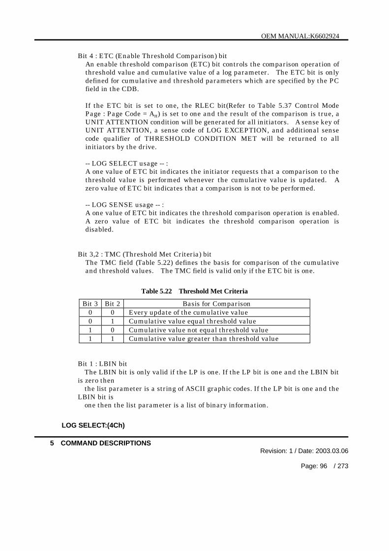
OEM MANUAL:K6602924
5 COMMAND DESCRIPTIONSRevision: 1 / Date: 2003.03.06
Page: 96 / 273
Bit 4 : ETC (Enable Threshold Comparison) bitAn enable threshold comparison (ETC) bit controls the comparison operation ofthreshold value and cumulative value of a log parameter. The ETC bit is onlydefined for cumulative and threshold parameters which are specified by the PCfield in the CDB.
If the ETC bit is set to one, the RLEC bit(Refer to Table 5.37 Control ModePage : Page Code = AH) is set to one and the result of the comparison is true, aUNIT ATTENTION condition will be generated for all initiators. A sense key ofUNIT ATTENTION, a sense code of LOG EXCEPTION, and additional sensecode qualifier of THRESHOLD CONDITION MET will be returned to allinitiators by the drive.
-- LOG SELECT usage -- :A one value of ETC bit indicates the initiator requests that a comparison to thethreshold value is performed whenever the cumulative value is updated. Azero value of ETC bit indicates that a comparison is not to be performed.
-- LOG SENSE usage -- :A one value of ETC bit indicates the threshold comparison operation is enabled.A zero value of ETC bit indicates the threshold comparison operation isdisabled.
Bit 3,2 : TMC (Threshold Met Criteria) bitThe TMC field (Table 5.22) defines the basis for comparison of the cumulativeand threshold values. The TMC field is valid only if the ETC bit is one.
Table 5.22 Threshold Met Criteria
Bit 3 Bit 2 Basis for Comparison0 0 Every update of the cumulative value0 1 Cumulative value equal threshold value1 0 Cumulative value not equal threshold value1 1 Cumulative value greater than threshold value
Bit 1 : LBIN bitThe LBIN bit is only valid if the LP is one. If the LP bit is one and the LBIN bit
is zero thenthe list parameter is a string of ASCII graphic codes. If the LP bit is one and the
LBIN bit isone then the list parameter is a list of binary information.
LOG SELECT:(4Ch)

OEM MANUAL:K6602924
5 COMMAND DESCRIPTIONSRevision: 1 / Date: 2003.03.06
Page: 97 / 273
Bit 0 : LP (List Parameter) bitThe LP bit indicates the type of the log parameter, data counter or listparameter.
If an initiator attempts to set the value of the LP bit to a value other than theone returned for the same parameter in the LOG SENSE command, the drivewill terminate the command with CHECK CONDITION status. The sense keywill be set to ILLEGAL REQUEST and the additional sense code will beINVALID FIELD IN PARAMETER LIST.
An LP bit of zero indicates that the parameter is a data counter. Data countersare associated with one or more events. Its cumulative parameter value will beincremented whenever one of those associated events occurs and the DU bit iszero. Each data counter has its own drive-defined maximum value. Uponreaching this maximum value, the drive will set the data counter associated DUbit to one to prevent further updating of this counter. And incrementing of allcounters in the same log page will be ceased until re- initialized by the initiatorvia a LOG SELECT command. If the data counter is at or reaches its maximumvalue during the execution of a command, the drive will complete the command.If the command completes correctly (except the data counter being at itsmaximum value) and if RLEC (Report Log Exception Condition) bit of thecontrol mode page is set to one, then the drive will terminate the command withCHECK CONDITION status and set the sense key to RECOVERED ERRORwith the additional sense code set to LOG COUNTER AT MAXIMUM.An LP bit of one indicates that the parameter is a list parameter. Listparameters are not counters and thus the ETC and TMC fields shall be set tozero by the initiator.
If more than one list parameter is defined in a single log page, the followingrules apply to assigning parameter codes :
1. The list parameter updated last will have a higher parameter code than theprevious list parameter, except as described in rule 2.
2. When the maximum parameter code value supported by the drive,determined by the available memory size, the drive will assign the lowestparameter code value to the next list parameter (i.e., wraparound parametercodes). If the associated command completes correctly (except for theparameter code being at its maximum value) and if the RLEC bit of the controlmode page is set to one, then the drive will terminate the command withCHECK CONDITION status and set the sense key to RECOVERED ERRORwith the additional sense code set to LOG LIST CODES EXHAUSTED.
LOG SELECT:(4Ch)

OEM MANUAL:K6602924
5 COMMAND DESCRIPTIONSRevision: 1 / Date: 2003.03.06
Page: 98 / 273
The Parameter Length field specifies the length in bytes of the followingParameter Value field. If the initiator sends a parameter length value thatresults in the truncation of the parameter value, the drive will terminate thecommand with CHECK CONDITION status. The sense key will be set toILLEGAL REQUEST with the additional sense code set to INVALID FIELD INPARAMETER LIST.
If the initiator sends a log parameter value that is not supported by the drive, thedrive will terminate the command with CHECK CONDITION status with a sensekey of ILLEGAL REQUEST and an additional sense code of INVALID FIELD INPARAMETER LIST.
Supported Log Pages (Page Code = 00H)
The supported log page is only defined for LOG SENSE command.It returns the list of log pages implemented by the drive.
Table 5.23 Supported Log Pages
BitByte
7 6 5 4 3 2 1 0
0 Reserved Page Code(00H)0 0 0 0 0 0 0 0
1 Reserved0 0 0 0 0 0 0 0
2 (MSB)Page Length (000AH)
3(LSB)
4 00H (Supported Log Page)
5 02H (Error Counter Write Page)
6 03H (Error Counter Read Page)
7 05H (Error Counter Verify Page)
8 06H (Non-Medium Error Page)
9 07H (Last n Error Events Page)
10 0DH (Temperature Page)
(cont’d)
LOG SELECT:(4Ch)

OEM MANUAL:K6602924
5 COMMAND DESCRIPTIONSRevision: 1 / Date: 2003.03.06
Page: 99 / 273
Table 5.23 Supported Log Pages (cont’d)
11 0EH (Start-Stop cycle counter Page)
12 0FH (Application client Page)
13 10H (Self-Test Results Page)
14 2FH (Informational Exceptions Page)
15 3EH (Factory Log Page)
The page length field specifies the length in bytes of the following supported pagelist. There is one byte for one page code ; therefore, the page length also indicatesthe total number of log pages supported by the drive.
The supported page list field will contain a list of all log page codes implementedby the drive in ascending order beginning with page code 00H.
Error Counter Log Pages (Page Code = 02H, 03H, 05H)
The formats of three supported error counter pages, read (page code 3H), write(page 2H), and verify (page 5H), are the same. The error counter page for readoperation is defined in Table 5.24 to represent all three pages. A page can returnone or more error counters which record events defined by the parameter codes(Table 5.25).
Table 5.24 Error Counter Read Page (Page Code = 3H)
BitByte
7 6 5 4 3 2 1 0
0 Reserved Page Code0 0 0 0 0 0 1 1
1 Reserved0 0 0 0 0 0 0 0
2 (MSB)Page Length (n)
3(LSB)
(cont’d)
LOG SELECT:(4Ch)

OEM MANUAL:K6602924
5 COMMAND DESCRIPTIONSRevision: 1 / Date: 2003.03.06
Page: 100 / 273
Table 5.24 Error Counter Read Page (Page Code = 3H) (cont’d)
Error Counter (s)
4 (MSB)Parameter Code
5(LSB)
6 DU DS TSD ETC TMC LBIN LP0 0
7 Parameter Length (8)
8 (MSB)• Parameter Value•15 (LSB)
||
n-8• Error Counter (Last)• (Length 12)
n+3
Table 5.25 Parameter Codes for Error Counter Pages
Parameter Code Description0000H
0001H
0002H
0003H
0004H
0005H
0006H
0007H -7FFFH
8000H -FFFFH
Error sectors corrected on the fly ECCError sectors corrected by ECC with possible delays (Note 1)Error sectors recovered with re-writes or re-readsTotal error sectors recoveredTotal times tried to recoverTotal bytes processed in block sizeTotal unrecovered error sectorsReservedVendor Unique
Note 1 : In case of error counter write page, a zero value will be returned on LOGSENSE command. A GOOD status will be returned on LOG SELECTcommand but no other actions will be performed.
Note 2 : The contents of error counter are vendor unique.
LOG SELECT:(4Ch)

OEM MANUAL:K6602924
5 COMMAND DESCRIPTIONSRevision: 1 / Date: 2003.03.06
Page: 101 / 273
Non-Medium Error Page (Page Code = 06H)
This page records the occurrences of recoverable error events other than write,read, or verify failures. This controller provide two vender specific errorcounters : track following error and positioning error (Table 5.27). Both of thesevendor specific error counts are included in the non-medium error count.
Table 5.26 Non-Medium Error Page (Page Code = 6H)
BitByte
7 6 5 4 3 2 1 0
0 Reserved Page Code0 0 0 0 0 1 1 0
1 Reserved0 0 0 0 0 0 0 0
2 (MSB)Page Length (n)
3(LSB)
Error Counter (s)
4 (MSB)Parameter Code
5(LSB)
6 DU DS TSD ETC TMC LBIN LP0 0
7 Parameter Length (8)
8 (MSB)• Parameter Value•15 (LSB)
||
n-8• Error Counter (Last)• (Length 12)
n+3
LOG SELECT:(4Ch)

OEM MANUAL:K6602924
5 COMMAND DESCRIPTIONSRevision: 1 / Date: 2003.03.06
Page: 102 / 273
Table 5.27 Non-Medium Error Event Parameter Codes
Parameter Code Description0000H
0001H-7FFFH
8000H-FFFFH
8009H
8015H
Non-Medium Error CountReservedVendor-Specific Error CountsTrack Following ErrorPositioning Error
Last n Error Events Page (Page Code = 07H)
Log page 7H is a list parameter page. Each list parameter is an error-event recordwhich contains drive-specific diagnostic information for a single error encounteredby the drive. There are 23 of these error-event records supported by thiscontroller. The length of a list parameter and the kinds of error-events will besupported are defined in the following Table 5.28. The content of the parametervalue field of each log PARAMETER is an ASCII character string which maydescribe the error event. The exact contents of the character string is also in thesame table.
Table 5.28 Last n Error Events Page(Page Code = 7H)
BitByte
7 6 5 4 3 2 1 0
0 Reserved Page Code0 0 0 0 0 1 1 1
1 Reserved0 0 0 0 0 0 0 0
2 (MSB)Page Length (n)
3(LSB)
Error Counter (s)
4 (MSB)Parameter Code
5(LSB)
6 DU DS TSD ETC TMC LBIN LP0 0 0 0 1
(cont’d)
LOG SELECT:(4Ch)

OEM MANUAL:K6602924
5 COMMAND DESCRIPTIONSRevision: 1 / Date: 2003.03.06
Page: 103 / 273
Table 5.28 Last n Error Events Page(Page Code = 7H) (cont’d)
7 Parameter Length (x)
8 (MSB)• Event Description
x+7 (LSB)||
n-y+4• Error Event (Last)
n+3 (Length y)
The parameter code in an error-event record indicates the relative time at whichthe error occurred. The higher the parameter code indicates the later an errorevent occurred. The valid parameter codes supported by this controller are from0000H to FFFFH.
When the drive reaches beyond the last supported parameter code (FFFFH) for anerror-event record, then a parameter code of (000H) is to be taken as wraparoundcodes.
Temperature Page (Page Code = 0DH)
This clause defines the optional temperature log page(page code 0DH).The temperature sensed in the device at the time the LOG SENSE command isperformed shall be returned in the parameter field defined by parameter code0000H.
Temperature equal to or less than zero Degrees Celsius shall be indicated by avalue of zero. If a valid temperature cannot be detected because of a sensor failureor other condition, the value returned shall be FFH.
The temperature should be reported with an accuracy of plus or minus threeCelsius Degrees while the device is operating at a steady state within theenvironmental limits specified for the device.
A reference temperature for the device provided by the device using parametercode 0001H.The one byte binary value should reflect the maximum reported sensortemperature in degrees Celsius at which the device is capable of operatingcontinuously without degrading the device’s operation or reliability beyondmanufacture accepted limit.
LOG SELECT:(4Ch)

OEM MANUAL:K6602924
5 COMMAND DESCRIPTIONSRevision: 1 / Date: 2003.03.06
Page: 104 / 273
Table 5.29 Temperature Page(Page Code = DH)
BitByte
7 6 5 4 3 2 1 0
0 Reserved Page Code0 0 0 0 1 1 0 1
1 Reserved0 0 0 0 0 0 0 0
2 (MSB)Page Length (12)
3(LSB)
4 Parameter Code (MSB)0 0 0 0 0 0 0 0
5 Parameter Code (LSB)0 0 0 0 0 0 0 0
6 DU DS TSD ETC TMC LBIN LP1 1 1
7 Parameter Length (2)
8 Reserved0 0 0 0 0 0 0 0
9 Temperature (Degrees Celsius)
10 Parameter Code (MSB)0 0 0 0 0 0 0 0
11 Parameter Code (LSB)0 0 0 0 0 0 0 1
12 DU DS TSD ETC TMC LBIN LP1 1 1
13 Parameter Length (2)
14 Reserved0 0 0 0 0 0 0 0
15 Reference Temperature (Degrees Celsius)
Start-Stop Cycle Counter Page (Page Code = 0EH)
This clause defines the optional start-stop cycle counter page(page code 0E.H).A device that implements the start-stop cycle counter page shall implement one ormore of the defined parameters. Table 5.30 shows the start-stop cycle counter pagewith all parameters present.
LOG SELECT:(4Ch)

OEM MANUAL:K6602924
5 COMMAND DESCRIPTIONSRevision: 1 / Date: 2003.03.06
Page: 105 / 273
Table 5.30 Start-Stop Cycle Counter Page(Page Code = 0EH)
BitByte
7 6 5 4 3 2 1 0
0 Reserved Page Code0 0 0 0 1 1 1 0
1 Reserved0 0 0 0 0 0 0 0
2 (MSB)Page Length (24H)
3(LSB)
4 (MSB)Parameter Code (0001H)
5 Date of Manufacture(LSB)
6 DU DS TSD ETC TMC LBIN LP
7 Parameter Length (06H)
8 (MSB)• Year of Manufacture• (4 ASCII Characters)11 (LSB)12 (MSB)
Week of Manufacture13 (2 ASCII Characters)
(LSB)14 (MSB)
Parameter Code (0002H)15 Accounting Date
(LSB)16 DU DS TSD ETC TMC LBIN LP
17 Parameter Length (06H)
18 (MSB)• Accounting Date Year• (4 ASCII Characters)21 (LSB)
(cont’d)
LOG SELECT:(4Ch)

OEM MANUAL:K6602924
5 COMMAND DESCRIPTIONSRevision: 1 / Date: 2003.03.06
Page: 106 / 273
Table 5.30 Start-Stop Cycle Counter Page(Page Code = 0EH) (cont’d)
22 (MSB)Accounting Date Week
23 (2 ASCII Characters)(LSB)
24 (MSB)Parameter Code (0003H)
25 Specified Cycle Count Over Device Lifetime(LSB)
26 DU DS TSD ETC TMC LBIN LP
27 Parameter Length (04H)
28 (MSB)• Specified Cycle Count Over Device Lifetime• (4 Byte Binary Number)31 (LSB)32 (MSB)
Parameter Code (0004H)33 Accumulated Start-Stop Cycles
(LSB)34 DU DS TSD ETC TMC LBIN LP
35 Parameter Length (04H)
36 (MSB)• Accumulated Start-Stop Cycles• (4 Byte Binary Number)39 (LSB)
The year and week in the year that the device was manufactured shall be set inthe parameter field defined by parameter code 0001H. The date of manufactureshall not be savable by the initiator via the LOG SELECT command. The date isexpressed in numeric ASCII characters (30H - 39H) in the form YYYYWW, as shownin Table 5.30.
The accounting date specified by parameter code 0002H is a parameter that mayoptionally be savable via the LOG SELECT command to indicate when the devicewas placed in service.
LOG SELECT:(4Ch)

OEM MANUAL:K6602924
5 COMMAND DESCRIPTIONSRevision: 1 / Date: 2003.03.06
Page: 107 / 273
If the parameter is not yet set or is not settable, the default value placed in theparameter field shall be 6 ASCII blank characters(20H). The field shall not bechecked for validity by this controller.
The Specified cycle count over device lifetime (parameter code 0003H) is aparameter provided by this controller. The specified cycle count over devicelifetime parameter shall not be savable by initiator via the LOG SELECTcommand. The parameter value is a 4 byte binary number.
The value indicates how many stop-start cycle may typically be executed over thelifetime of the device without degrading the device’s operation or reliabilityoutside the limits specified by the manufacture of the device.
The accumulated start-stop cycles (parameter code 0004h) is a parameter providedby this controller. The accumulated start-stop cycles parameter shall not besavable by initiator via the LOG SELECT command. The parameter value is a 4-byte binary number. The value indicates how many start-stop cycles the device hasdetected since its date of manufacture.
Application Client Page (Page Code = 0FH)
The application client page (see Table 5.31) provides a place for application clientsto store system information. The page code for the application client page is 0Fh.
Table 5.31 Application Client Page(Page Code = 0FH)
BitByte
7 6 5 4 3 2 1 0
0 Reserved Page Code0 0 0 0 1 1 1 1
1 Reserved0 0 0 0 0 0 0 0
2 (MSB)Page Length (4000H)
3(LSB)
(cont’d)

OEM MANUAL:K6602924
5 COMMAND DESCRIPTIONSRevision: 1 / Date: 2003.03.06
Page: 108 / 273
Table 5.31 Application Client Page(Page Code = 0FH) (cont’d)
Application Client Log Parameters
4• First Application Client Log Parameter•
259||
16132• 64th Application Client Log Parameters•
16387
Parameter codes 0000h through 003Fh are for general usage application clientdata. The intended use for this information is to aid in describing the systemconfiguration and system problems, but the exact definition of the data isapplication client specific. The general usage application client data parametersall have the format shown in Table 5.32.
Table 5.32 General usage application client parameter data
BitByte
7 6 5 4 3 2 1 0
0 (MSB)Parameter Code (0000H to 003FH)
1(LSB)
2 DU DS TSD ETC TMC LBIN LP1 0 0 0 1 1
3 Parameter Length (FCH)
4• General Usage Parameter Bytes•
255
For general usage application client data, the value in the Parameter Code fieldshall be between 0000h and 003Fh. The first supported general usage applicationclient parameter code shall be 0000h and additional supported parameters shallbe sequentially numbered.
LOG SELECT:(4Ch)

OEM MANUAL:K6602924
5 COMMAND DESCRIPTIONSRevision: 1 / Date: 2003.03.06
Page: 109 / 273
The general usage parameter is savable by initiator via the LOG SELECTCommand.
If the parameter is not yet set, the default value placed in the parameter field shallbe all zero data.
If the parameter control field(byte2) is not satisfied in Table 5.32, the CHECKCONDITION Status with the ILLEGAL REQUEST Sense key is reported.
Self-Test Results Page (Page Code = 10H)
The Self-Test Results log page provides the results from the twenty most recentself-tests.Results from the most recent self-test or the self-test currently in progress shall bereported in the first self-test log parameter; results from the second most recentself-test shall be reported in the second self-test log parameter; etc. If fewer thantwenty self-tests have occurred, the unused self-test log parameter entries shall bezero filled.
Table 5.33 Self-Test Results Page(Page Code = 10H)
BitByte
7 6 5 4 3 2 1 0
0 Reserved Page Code0 0 0 1 0 0 0 0
1 Reserved0 0 0 0 0 0 0 0
2 (MSB)Page Length (190H)
3(LSB)
Self-Test Results Log Parameters
4• First Self-Test Results Log Parameters•23
||
384• Twentieth Self-Test Results Log Parameters•
403LOG SELECT:(4Ch)
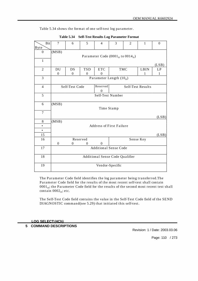
OEM MANUAL:K6602924
5 COMMAND DESCRIPTIONSRevision: 1 / Date: 2003.03.06
Page: 110 / 273
Table 5.34 shows the format of one self-test log parameter.
Table 5.34 Self-Test Results Log Parameter Format
BitByte
7 6 5 4 3 2 1 0
0 (MSB)Parameter Code (0001H to 0014H)
1(LSB)
2 DU DS TSD ETC TMC LBIN LP0 0 0 0 1 1
3 Parameter Length (10H)
4 Self-Test Code Reserved Self-Test Results0
5 Self-Test Number
6 (MSB)Time Stamp
7(LSB)
8 (MSB)• Address of First Failure•15 (LSB)16 Reserved Sense Key
0 0 0 017 Additional Sense Code
18 Additional Sense Code Qualifier
19 Vendor-Specific
The Parameter Code field identifies the log parameter being transferred.TheParameter Code field for the results of the most recent self-test shall contain0001H; the Parameter Code field for the results of the second most recent test shallcontain 0002H; etc.
The Self-Test Code field contains the value in the Self-Test Code field of the SENDDIAGNOSTIC command(see 5.29) that initiated this self-test.
LOG SELECT:(4Ch)

OEM MANUAL:K6602924
5 COMMAND DESCRIPTIONSRevision: 1 / Date: 2003.03.06
Page: 111 / 273
Table 5.35 Self-Test Results Values
Self-TestResultsValue
Description
0H The self-test completed without error.1H The background self-test was aborted by the application client
using a SEND DIAGNOSTIC command(see 5.29) with the Self-Test Code field set to (100)b (Abort background self-test).
2H The self-test routine was aborted by an application client using amethod other than a SEND DIAGNOSTIC command(see 5.29)with the Self-Test Code field set to (100)b.
3H An unknown error occurred while the device server was executingthe self-test and the device server was unable to complete theself-test.
4H The self-test completed with a failure in a test segment, and thetest segment that failed is not known.
5H The first segment of the self-test failed.6H The second segment of the self-test failed.7H Another segment of the self-test failed (see the Self-Test Segment
Number field).8H-EH Reserved
FH The self-test is in progress.
The Self-Test Number field identifies the self-test that failed and consists of either:
1) the number of the segment that failed during the set-test; or2) the number of the test that failed and the number of the segment in which the
test was run, using a vendor specific method for placing the two values in theone field.
When the segment in which the failure occurred cannot or need not be identified,the Self-Test Number field shall contain 00H.
The Time Stamp field contains the total accumulated power-on hours for thedevice server at the time the self-test was completed. If the test is still in progress,the content of the Time Stamp field shall be zero. If the power-on hours for thedevice at the time the self-test was completed is greater than FFFFH then thecontent of the Time Stamp field be FFFFH.
LOG SELECT:(4Ch)
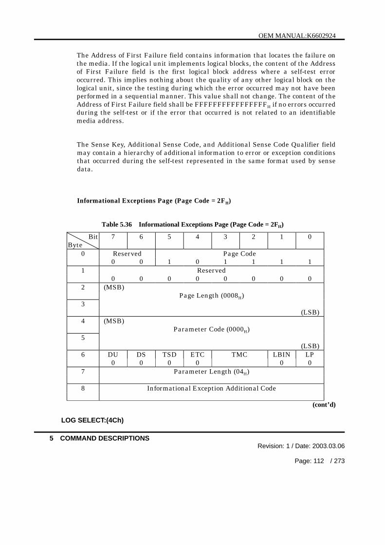
OEM MANUAL:K6602924
5 COMMAND DESCRIPTIONSRevision: 1 / Date: 2003.03.06
Page: 112 / 273
The Address of First Failure field contains information that locates the failure onthe media. If the logical unit implements logical blocks, the content of the Addressof First Failure field is the first logical block address where a self-test erroroccurred. This implies nothing about the quality of any other logical block on thelogical unit, since the testing during which the error occurred may not have beenperformed in a sequential manner. This value shall not change. The content of theAddress of First Failure field shall be FFFFFFFFFFFFFFFFH if no errors occurredduring the self-test or if the error that occurred is not related to an identifiablemedia address.
The Sense Key, Additional Sense Code, and Additional Sense Code Qualifier fieldmay contain a hierarchy of additional information to error or exception conditionsthat occurred during the self-test represented in the same format used by sensedata.
Informational Exceptions Page (Page Code = 2FH)
Table 5.36 Informational Exceptions Page (Page Code = 2FH)
BitByte
7 6 5 4 3 2 1 0
0 Reserved Page Code0 0 1 0 1 1 1 1
1 Reserved0 0 0 0 0 0 0 0
2 (MSB)Page Length (0008H)
3(LSB)
4 (MSB)Parameter Code (0000H)
5(LSB)
6 DU DS TSD ETC TMC LBIN LP0 0 0 0 0 0
7 Parameter Length (04H)
8 Informational Exception Additional Code
(cont’d)
LOG SELECT:(4Ch)

OEM MANUAL:K6602924
5 COMMAND DESCRIPTIONSRevision: 1 / Date: 2003.03.06
Page: 113 / 273
Table 5.36 Informational Exceptions Page (Page Code = 2FH) (cont’d)
9 Informational Exception Additional Sense Code Qualifier
10 Current Measured Temperature(Degrees Celsius)
11 Maximum Temperature Threshold(Degrees Celsius)
If the informational exception additional sense code field contains zero, noinformational exception condition is pending and contents of the informationalexception additional sense code qualifier field are unspecified. If theinformational exception additional sense code field contains any value other thanzero, an informational exception condition exists that has an additional sense codeindicated by informational exception additional sense code field and an additionalsense code qualifier indicated by the informational exception additional sense codequalifier field.
The current measured temperature field reports temperature of the device.Temperature equal to or less than zero Degrees Celsius shall be indicated by avalue of zero. If a valid temperature cannot be detected because of a sensor failureor other condition, the value returned shall be FFH.
The temperature should be reported with an accuracy of plus or minus threeCelsius Degrees while the device is operating at a steady state within theenvironmental limits specified for the device
The maximum temperature threshold field reports maximum temperaturethreshold of the device.
Factory Log Page (Page Code = 3EH)
Table 5.37 Factory Log Page (Page Code = 3EH)
BitByte
7 6 5 4 3 2 1 0
0 Reserved Page Code0 0 1 1 1 1 1 0
1 Reserved0 0 0 0 0 0 0 0
(cont’d)LOG SELECT:(4Ch)

OEM MANUAL:K6602924
5 COMMAND DESCRIPTIONSRevision: 1 / Date: 2003.03.06
Page: 114 / 273
Table 5.37 Factory Log Page (Page Code = 3EH) (cont’d)
2 (MSB)Page Length (0008H)
3(LSB)
4 (MSB)Parameter Code (0000H)
5(LSB)
6 DU DS TSD ETC TMC LBIN LP0 0 0 0 0 0
7 Parameter Length (04H)
8 (MSB)| Power On Time11 (LSB)12 (MSB)
Parameter Code (0008H)13
(LSB)14 DU DS TSD ETC TMC LBIN LP
0 0 0 0 0 015 Parameter Length (04 H)
16 (MSB)| Next S.M.A.R.T. Measurement Time19 (LSB)
The parameter code 0000H is Power On Time. This parameter code representsthe number of the controller power on minutes.
The parameter code 0008H is Next S.M.A.R.T. Measurement Time. Thisparameter reports the time, in minutes, to the next scheduled interrupt for aS.M.A.R.T. measurement.
LOG SELECT:(4Ch)

OEM MANUAL:K6602924
5 COMMAND DESCRIPTIONSRevision: 1 / Date: 2003.03.06
Page: 115 / 273
5.4 H)
Byte7 5 4 2 1
0 Operation Code (4D )0 0 0 1 0
1 Logical Unit Number PPC SP0 0
2 PC
3 Reserved0 0 0 0 0
40 0 0 0 0 0
(MSB)Parameter Pointer
(LSB)7
Allocation Length8
9 Vendor Unique Flag Link0 0 0 0
statistical information maintained by the drive. This command allows the initiatorto request only one log page from the drive at a time.
specified log page of parameter code values (16-bit unsigned integers) which has beenupdated since the last LOG SELECT or SENSE command. And only those
A PPC bit of zero will cause the drive to return the number of bytes specified by theallocation length field in ascending order of parameter codes beginning with the
parameter pointer field of zero will cause the drive to return all available logparameters for the specified log page to the initiator subject to the allocation length.
PPC = 0 only.
LOG SENSE:(4Dh)

OEM MANUAL:K6602924
5 COMMAND DESCRIPTIONSRevision: 1 / Date: 2003.03.06
Page: 116 / 273
The SP bit works as it does in the LOG SELECT command. It provides the optionfor the initiator to save all log parameters, identified as savable by the DS bit, of thespecified log page to the disk after the LOG SENSE operation has been performed.
The PC (page control) field defines the type of parameter values to be selected (seeTable 5.18). The parameter values returned by a LOG SENSE command aredetermined as the following priority list :
1. The last updated parameter values.2. The saved values are returned if an update has not occurred since the last
power-on, hard RESET condition, or BUS DEVICE RESET message.3. The default values are returned if an update has not occurred since the last
power-on, hard RESET condition, or BUS DEVICE RESET message andsaved values are not available.
The Page code field specifies which log page is requested from the drive.A reserved or not implemented page code requested by the initiator will cause thedrive to terminate the command with CHECK CONDITION status. The sense keywill be set to ILLEGAL REQUEST and the additional sense code will be INVALIDFIELD IN CDB.
The parameter pointer field is used by the initiator to request log parametersbeginning from a specific parameter code to the maximum allocation length or themaximum parameter code supported by the drive, whichever is less. If the value ofthe parameter pointer field is larger than the largest supported parameter code ofthe specified log page, the drive will terminate the command with CHECKCONDITION status. The sense key will be set to ILLEGAL REQUEST and theadditional sense code will be INVALID FIELD IN CDB.
Log parameters within the specified log page will be returned in ascendingparameter code order.
The Log Sense page format is as described in the LOG SELECT command (section5.3).
LOG SENSE:(4Dh)

OEM MANUAL:K6602924
5 COMMAND DESCRIPTIONSRevision: 1 / Date: 2003.03.06
Page: 117 / 273
5.5 MODE SELECT:(15H)
BitByte
7 6 5 4 3 2 1 0
0 Operation Code (15H)0 0 0 1 0 1 0 1
1 Logical Unit Number PF Reserved SP0 0 0
2 Reserved0 0 0 0 0 0 0 0
3 Reserved0 0 0 0 0 0 0 0
4 Parameter List Length
5 Vendor Unique Reserved Flag Link0 0 0 0 0 0
The MODE SELECT command provides a means for the host computer to specify orchange medium, logical unit, controller, or peripheral device parameters to thecontroller. There are some parameters which cannot be changed by the hostcomputer.With this command the host computer can control error recovery, disconnection /reconnection, medium formatting, and caching.
The MODE SELECT command is used with the MODE SENSE command (see 5.7).The MODE SENSE command is used to request the controller to transfer parametersto the host computer.
The controller manages the following three types of values as MODE SELECT data :
· Default values: The default values are stored in the system area written withinthe drive.
· Current values: The current values are used by the controller during operationsand stored in controller RAM.
· Saved values: The saved values are stored in the system area of the drive.The controller saves the current values on the drive as specifiedby the host computer with the MODE SELECT or FORMATUNIT command.
These values become the latest saved values.
MODE SELECT:(15h)

OEM MANUAL:K6602924
5 COMMAND DESCRIPTIONSRevision: 1 / Date: 2003.03.06
Page: 118 / 273
By making use of the save function, the host computer can eliminate the reissuing ofthe MODE SELECT command each time the controller is powered on; that is, thecontroller can automatically restore the current values from the saved values.
The PF (Page Format) bit is ignored. All data must comply to the pages as describedin this manual.
The SP (Save Parameters) bit, when set to 1, indicates that the controller saves thisspecified page and parameters (current values) into the system area of the drive afterupdating the parameters in the specified page. The following pages are savable:
• Read-write error recovery page (page code 1H)• Disconnect-reconnect page (page code 2H)• Verify error recovery page (page code 7H)• Caching page (page code 8H)• Control mode page (page code AH)• Informational Exceptions Condition page (page code 1CH)
When the SP bit is set to 0, the controller only updates the parameters and does notsave them.
The Parameter List Length specifies the length in bytes of the MODE SELECTparameter list to be transferred in the Data Out phase. A parameter list length of 0specifies that no data is to be transferred. This condition, however, is not consideredan error.
The Mode Select Parameter List (Table 5.38) consists of a 4-byte header, followed byzero or one block descriptors, followed by zero or more page descriptors.
The 4-byte Mode Select header must always be transferred whenever the ModeSelect parameter list is transferred. If this is not satisfied, the CHECKCONDITION status with ILLEGAL REQUEST sense key is reported.
The controller will create the CHECK CONDITION status with ILLEGALREQUEST sense key if an invalid field or bit value is specified as follows:
If the controller cannot implement the exact value of parameter requested by thehost computer and the parameter rounding is permitted, the controller rounds thevalue to its nearest value within its supporting range. In this case, the controllercreates CHECK CONDITION status with RECOVERED ERROR sense key afterexecuting the command and the additional sense code (Sense data byte 12) set to 37H
(ROUNDED PARAMETER).The host computer can also check the rounded value using a MODE SENSEcommand requesting the current value.
MODE SELECT:(15h)
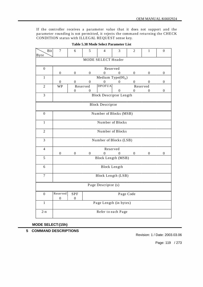
OEM MANUAL:K6602924
5 COMMAND DESCRIPTIONSRevision: 1 / Date: 2003.03.06
Page: 119 / 273
If the controller receives a parameter value that it does not support and theparameter rounding is not permitted, it rejects the command returning the CHECKCONDITION status with ILLEGAL REQUEST sense key.
Table 5.38 Mode Select Parameter List
BitByte
7 6 5 4 3 2 1 0
MODE SELECT Header
0 Reserved0 0 0 0 0 0 0 0
1 Medium Type(00H)0 0 0 0 0 0 0 0
2 WP Reserved DPOFUA Reserved0 0 0 0 0 0
3 Block Descriptor Length
Block Descriptor
0 Number of Blocks (MSB)
1 Number of Blocks
2 Number of Blocks
3 Number of Blocks (LSB)
4 Reserved0 0 0 0 0 0 0 0
5 Block Length (MSB)
6 Block Length
7 Block Length (LSB)
Page Descriptor (s)
0 Reserved SPF Page Code0 0
1 Page Length (in bytes)
2-n Refer to each Page
MODE SELECT:(15h)

OEM MANUAL:K6602924
5 COMMAND DESCRIPTIONSRevision: 1 / Date: 2003.03.06
Page: 120 / 273
The page descriptor(s) case of page_0 mode page format is defined in Table 5.38.
The page descriptor(s) case of sub_page mode page format is defined in Table 5.39.
Table 5.39 Mode Select (Sub_Page Mode) Page Descriptor(s)
BitByte
7 6 5 4 3 2 1 0
Page Descriptor (s)
0 Reserved SPF Page Code0 1
1 Sub Page Code
2-3 Page Length (in bytes)
4-n Refer to each Page
The Medium Type field must always be loaded with code 00H and identify the defaultmedium type.
The controller ignores WP and DPOFUA bit in MODE SELECT command.
The Block Descriptor Length field specifies the total length in bytes of the blockdescriptors. The eligible length values are 0 and 8. This means that at most oneblock descriptor can be specified.
The Block Descriptor field specifies the area on the medium that is accessible to thehost computer.
The Number of Blocks field specifies the number of logical blocks on the medium thatsatisfy the block length in the block descriptor. The number of blocks field = 0indicates that the number of blocks value is not changed from the current value if theblock length of the Block Descriptor remains the same as the current value. And ifthe block length of the Block Descriptor is different from the current value, thecontroller uses the default maximum number of blocks as the number of blocks value.
The block length field specifies the length in bytes of the logical block.
Please refer to “Product Specifications” for the information of the eligible block lengthvalues.
MODE SELECT:(15h)

OEM MANUAL:K6602924
5 COMMAND DESCRIPTIONSRevision: 1 / Date: 2003.03.06
Page: 121 / 273
Each page is preceded by a 2-byte or 4-byte page header that defines the SPF(SubPage Format) and page code and page length.
The Page Code field specifies the meaning of the bytes following the page length field.The Page Code field must be loaded with a page code that is supported by thecontroller. The page codes supported by the SCSI controller are listed below.
Page Code Meaning1H Read-write error recovery page2H Disconnect-reconnect page3H Format device page4H Rigid disk geometry page7H Verify error recovery page8H Caching pageAH Control mode pageCH Notch and partition page
18H Logical unit control page19H Port control page1AH Power condition page1CH Informational exceptions control page
The Page Length field specifies the number of bytes that follow the page length field.The Page Length field must be loaded with a page length value that is supported bythe controller. This value is reported by the controller to the host computer bychecking it in the page length field of the Mode Sense data.
The controller assumes and reports a contiguous page area even if the page containsunsupported fields.
The host computer can transfer all pages supported by the controller includingunchanged pages. The page codes may be specified in any order.
The controller manages the current and saved values on page 19H for each hostcomputer (initiator) . Consequently, the host computers that are connected to thecontroller can control the functions specified on pages 19H independently.
The block descriptors and page code 19H sub page code 03H are managed on acontroller unit basis.When value in these areas are changed, the controller reports the CHECKCONDITION status with UNIT ATTENTION sense key to the first command sent byany initiator other than the one that changed these value. The host computer mustload 0’s into the corresponding fields and bits that are flagged as unchangeable inthe Mode Sense data.
MODE SELECT:(15h)

OEM MANUAL:K6602924
5 COMMAND DESCRIPTIONSRevision: 1 / Date: 2003.03.06
Page: 122 / 273
Precautions to be observe on the host computer side
It is recommended that the host computer issue a MODE SENSE commandrequesting the controller to return all changeable values prior to issuing anyMODE SELECT commands, in order to find out the pages supported by thecontroller, page lengths, and changeable fields or bits.
It is recommended that the host computer issues the RESERVE UNIT commandprior to executing the MODE SELECT command which intends to change the page3H (Format parameter) and/or page 4H (Geometry parameter), and issues theRELEASE UNIT command after the completion of the FORMAT UNIT command.This procedure will prevent another host computer from issuing different ModeSelect parameters to the same unit prior to the execution of the FORMAT UNITcommand.
MODE SELECT:(15h)

OEM MANUAL:K6602924
5 COMMAND DESCRIPTIONSRevision: 1 / Date: 2003.03.06
Page: 123 / 273
[ Mode Page 1H ]
Table 5.40 Read - Write Error Recovery Page (Page Code = 1H)
BitByte
7 6 5 4 3 2 1 0
0 Reserved SPF Page Code(01H)0 0 0 0 0 0 0 1
1 Page Length(0AH)0 0 0 0 1 0 1 0
2 AWRE ARRE TB RC EER PER DTE DCR
3 Read Retry Count
4 Correction Span
5 Head Offset Count
6 Data Strobe Offset Count
7 Reserved0 0 0 0 0 0 0 0
8 Write Retry Count
9 Reserved0 0 0 0 0 0 0 0
10 Recovery Time Limit (MSB)
11 Recovery Time Limit (LSB)
ARRE, TB, RC and DCR bits in error recovery flag (byte 2) are applied to the dataarea of the blocks during Read operation. AWRE is applied to the data area of theblocks during Write operation. PER and DTE are applied to errors occurredduring read, write or seek operation. EER is ignored.
Bit 7 : AWRE (Automatic Write Reallocation for defective data blocksEnabled)When set to one , allows the controller to automatically relocate badblocks detected during write operations.This function is applied to WRITE, WRITE EXTENDED command butnot applied to FORMAT UNIT command.
MODE SELECT:(15h)

OEM MANUAL:K6602924
5 COMMAND DESCRIPTIONSRevision: 1 / Date: 2003.03.06
Page: 124 / 273
The drive performs automatic reallocation upon the abnormaltermination of write operation after the drive proceeds error recoveryprocess which is specified by mode select.The drive shall create CHECK CONDITION status with sense key ofMEDIUM ERROR when the drive fails to do automatic reallocation.When set to 0, this bit indicates that the controller does not performautomatic reallocation of defective data blocks during write operations.
Bit 6 : ARRE (Automatic Read Reallocation for defective data blocks Enabled)When set to one, allows the controller to automatically relocate badblocks detected during read operations.This function is applied to READ, READ EXTENDED command.The drive performs automatic reallocation if the data recovery hasbeen done normally after the drive proceeds error recovery processwhich is specified by mode select.The drive shall create CHECK CONDITION status with sense key ofMEDIUM ERROR when the drive fails to do automatic reallocation.When set to 0, this bit indicates that the controller does not performautomatic reallocation of defective data blocks during read operations.
Bit 5 : TB (Transfer Block)When set to 1, this bit specifies that the data in the error block(recoverable or unrecoverable) is to be transferred to the hostcomputer.When this bit is set to 0, it specifies that the error block data is not tobe transferred to the host computer.
Note : In either case, the information byte area of the sensedata is loaded with the error block address.
Bit 4 : RC (Read Continuous)When set to 1, this bit specifies that the controller is to transfer theentire requested length of data without attempting an error recoveryprocedure. The controller may send data which may be fabricated(e.g., garbage data in the buffer) to maintain a continuous flow of data.This bit is given precedence over the other bits in this byte.When this bit is set to 0, it indicates that error recovery operationswhich cause reasonable delays are acceptable during the data transfer.
MODE SELECT:(15h)

OEM MANUAL:K6602924
5 COMMAND DESCRIPTIONSRevision: 1 / Date: 2003.03.06
Page: 125 / 273
Bit 3 : EER (Enable Early Recovery)When set to 1, this bit specifies that the controller is to attempt errorcorrection, if possible, before applying retries.When this bit is set to 0, it specifies that the controller is to carry outthe predetermined number of retries before attempting errorcorrection.
Bit 2 : PER (Post Error)When set to 1, this bit specifies that the controller is to enable thereporting of the CHECK CONDITION status with the RECOVEREDERROR sense key.When this bit is set to 0, it specifies that the controller does not set theCHECK CONDITION status for RECOVERED ERROR.
Bit 1 : DTE (Disable Transfer on Error)When set to 1, this bit specifies that the controller is to create theCHECK CONDITION status upon detection of the first error block,irrespective of whether the error is recoverable or not.When this bit is set to 0, it indicates that the controller can continuetransferring the recovered data to the host computer until anunrecoverable error occurs or the specified length of data bytes to betransferred have exhausted.
Bit 0 : DCR (Disable Correction)When set to 1, this bit specifies that the controller must not attempterror correction during the error recovery procedure.When this bit is set to 0, it indicates that the controller can attempterror correction during the error recovery procedure.
Combinations of error control bits (bits 0-3) are summarized in Table 5.41.There are some bit combinations that are not allowed.
MODE SELECT:(15h)

OEM MANUAL:K6602924
5 COMMAND DESCRIPTIONSRevision: 1 / Date: 2003.03.06
Page: 126 / 273
Table 5.41 Error Control Bit Combinations3
EER2
PER1
DTE0
DCRDescription
0 0 0 0 - Retries then correction are attempted (EER &DCR off).
- Recovered data are transferred to the hostcomputer with no CHECK CONDITION status(PER off). Data transfer stops only when anunrecoverable error is encountered, in which casethe CHECK CONDITION status is created.
- The transfer of unrecoverable data block dependson the setting of the TB bit.
0 0 0 1 - Same as (0000) above but no correction applied(DCR on).
0 0 1 0 - Invalid request (DTE on, PER off)0 0 1 1 - Invalid request (DTE on, PER off)0 1 0 0 - Same as (0000) above except that the last
recovered block is reported with RECOVEREDERROR sense key (PER on) at the end of the datatransfer if a recoverable error occurs.
0 1 0 1 - Same as (0100) above but no correction applied(DCR on).
0 1 1 0 - Retries then correction are attempted (EER &DCR off) on first error.
Transfer is then stopped (DTE on).- The controller creates the CHECK CONDITION
status with RECOVERED ERROR sense key (PERon) if the error is corrected. The CHECKCONDITION status is also created if the error isunrecoverable.
- Transfer of the recovered or unrecovered blockdepends on the setting of the TB bit.
Note : It is recommended that this mode be usedwith the TB bit set on.
0 1 1 1 - Same as (0110) above but no correction applied(DCR on).
1 0 0 0 - Same as (0000) above except that correction isapplied first (EER on, DCR off).
1 0 0 1 - Invalid request (EER on, DCR on)1 0 1 0 - Invalid request (PER off, DTE on)
(cont’d)
MODE SELECT:(15h)

OEM MANUAL:K6602924
5 COMMAND DESCRIPTIONSRevision: 1 / Date: 2003.03.06
Page: 127 / 273
Table 5.41 Error Control Bit Combinations (cont’d)
1 0 1 1 - Invalid request (EER on, DCR on) (PER off, DTE on)
1 1 0 0 - Same as (0100) above except that correction isapplied first (EER on, DCR off).
1 1 0 1 - Invalid request (EER on, DCR on)1 1 1 0 - Same as (0110) above except that correction is
applied first (EER on, DCR off).1 1 1 1 - Invalid request (EER on, DCR on)
Read Retry Count and Write Retry Count specify the host permissible retry countsfor an error recovery operations executed by the controller.The controller retries within these retry counts specified by the host computer.Retry count 0 indicates that the host permissible error recovery operations are notexecuted, The error correction by ECC and the host impermissible recoveryoperations, however, may be executed if it is permitted.
The correction Span specifies the maximum error bits span to be corrected by thecontroller.The controller corrects an ECC error within the specified maximum error bits span,if the error correction is permitted.
Head Offset Count specifies the offset value of the head position from the center oftrack. (Count value range ; FEH to 02H = -2 to +2, + ; offset toward the innerperiphery.)The controller executes the head offset as the specified count value.The controller will change the offset value depending on the retry count in theerror retry
sequence. (See 2.3.1). After the retry operation, the offset is returned to theCount value. When the write operation is executed, the offset is always returnedto 0.
Data Strobe Offset Count specifies the offset value of the data strobing level fromthe standard level. (Count value range ; FEH to 02H = -2 to +2)The controller will change the offset value depending on the retry count in theerror retry sequence. (See 2.3.1) After the retry operation, the offset is returnedto the Count value. When the write operation is executed, the offset is alwaysreturned to 0.
MODE SELECT:(15h)

OEM MANUAL:K6602924
5 COMMAND DESCRIPTIONSRevision: 1 / Date: 2003.03.06
Page: 128 / 273
Recovery Time Limit specifies the time limit in 1ms increments, in which thecontroller can execute the data error retrials.The controller attempts the error recovery operation per command, within theshorter time either of the Retry Count or the Recovery Time Limit.There is the case that the time out is held pending until one operation finisheseven if the time out is detected after starting error recovery operation. In thiscase, the actual time limit sometimes exceeds the time limit specified by the hostcomputer.If the Recovery Time Limit is set to 0000H, the controller shall use its defaultvalue.If the Recovery Time Limit is set to FFFFH, the controller waits until the recoveryoperation has terminated.
MODE SELECT:(15h)

OEM MANUAL:K6602924
5 COMMAND DESCRIPTIONSRevision: 1 / Date: 2003.03.06
Page: 129 / 273
[ Mode Page 2H ]
Table 5.42 Disconnect - Reconnect Page (Page Code = 2H )
BitByte
7 6 5 4 3 2 1 0
0 Reserved SPF Page Code(02H)0 0 0 0 0 0 1 0
1 Page Length(0EH)0 0 0 0 1 1 1 0
2 Bus Full Ratio
3 Buffer Empty Ratio
4 Bus Inactivity Limit (MSB)
5 Bus Inactivity Limit (LSB)
6 Disconnect Time Limit (MSB)
7 Disconnect Time Limit (LSB)
8 Connect Time Limit (MSB)
9 Connect Time Limit (LSB)
10 Maximum Burst Size (MSB)0 0 0 0 0 0 0 0
11 Maximum Burst Size (LSB)0 0 0 0 0 0 0 0
12 Reserved Fair Arbitration DIMM DTDC0
13 Reserved0 0 0 0 0 0 0 0
14 Reserved0 0 0 0 0 0 0 0
15 Reserved0 0 0 0 0 0 0 0
Buffer Full Ratio and Buffer Empty Ratio parameters are the numerator of afractional multiplier that has 256 as its denominator and these parametersindicate the full or empty ratio of buffer.
MODE SELECT:(15h)
OEM MANUAL:K6602924
5 COMMAND DESCRIPTIONSRevision: 1 / Date: 2003.03.06
Page: 130 / 273
The controller calculates the timing to be considered as Buffer Full / Empty in thenumber of blocks based on the specified ratio, the transfer data size and the buffersize.
Buffer Full Ratio specifies the amount of data considered as Buffer Full during theREAD operation, and the controller uses it as a timing of reconnection for datatransfer to the host computer.The controller uses the value which is rounded down in the number of blocks basedon the ratio.If Buffer Full Ratio is set to 0, the controller considers as Buffer Full when the firstblock to be read is detected.Further, the controller gives priority to the internal algorithm irrespective of thevalue specified in the Buffer Full Ratio.
The Buffer Empty Ratio specifies the amount of written data considered as BufferEmpty during the WRITE operation, and the controller uses it as a timing ofreconnection for data transfer from the host computer.The controller uses the value which is rounded down in the number of blocks basedon the ratio.If Buffer Empty Ratio is set to 0, the controller considers as Buffer Empty whenthe first block to be written is detected.The controller uses this parameter when the reconnection is attempted for datatransfer after the disconnection caused by Buffer Full, then this parameter iseffective when the amount of transfer data exceeds the buffer size. However,when the data transfer from the host computer and the write operation to the diskdrive are overlapped, this parameter may not be used even if the amount oftransfer data exceeds the buffer size.Further, the controller gives priority to the internal algorithm irrespective of thevalue specified in the Buffer Empty Ratio.
Bus Inactivity Limit is specified by the host computer as the maximum time in 100micro seconds increments which the controller is allowed to maintain the bus busywithout handshaking until it shall disconnect.Bus Inactivity Limit of 0 shows that there is no limit in time.The controller supports Bus Inactivity Limit = 0 only.
Disconnect Time Limit is specified by the host computer as the minimum time in100 micro seconds increments which the controller continues disconnection untilreconnection is initiated.Disconnect Time Limit of 0 shows that there is no limit in time.This field needs to be always specified to 0 as the controller does not support thisfield.
MODE SELECT:(15h)

OEM MANUAL:K6602924
5 COMMAND DESCRIPTIONSRevision: 1 / Date: 2003.03.06
Page: 131 / 273
Connect Time Limit is specified by the host computer the maximum time in 100micro seconds increments which the controller continues connection untildisconnection is initiated.Connect Time Limit of 0 shows that there is no limit in time.This field needs to be always specified to 0 as the controller does not support thisfield.
Maximum Burst Size is specified by the host computer the maximum data amountin bytes, in 512 bytes increments, which the controller can transfer per eachconnection. (Note : the count one represents 512 bytes.) When the specified dataamount has transferred, the controller disconnects. This field of zero indicatesthere is no limitation with the transfer size per connection. This field needs to bealways specified to 0 as the controller does not support this field.
Fair Arbitration is specified whether SCSI bus fairness function.Fair Arbitration of 000b indicates the controller does not perform SCSI busfairness function.Fair Arbitration of 001b indicates the controller perform SCSI bus fairnessfunction.When specified expect 000b and 001b as Fair Arbitration, let the controller beCHECK CONDITION status by ILLEGAL REQUEST sense key.
DTDC (Data Transfer Disconnect Control) is specified by the host computer as theconditions that control SCSI bus disconnect.
Table 5.43 DTDC (Data Transfer Disconnect Control)
Bit2 ,1, 0
Disconnect Control
000 Disconnect control is not implemented. Disconnection iscontrolled by the other field in this page.
001 No disconnection is executed for the period starting thecommand transfer over the full data transfer. ConnectTime Limit and Bus Inactivity Limit are ignored during thedata transfer.
010 Reserved011 No disconnection is executed for the period starting the
command transfer, until the command completed.Connect Time Limit and Bus Inactivity Limit are ignoredafter the data transfer started.
1XX ReservedNote: X denotes a don’t care condition.
MODE SELECT:(15h)

OEM MANUAL:K6602924
5 COMMAND DESCRIPTIONSRevision: 1 / Date: 2003.03.06
Page: 132 / 273
DIMM (Disconnect Immediate) is specified by the host computer whether or notthe controller disconnects the SCSI bus until the data transfer is initiated afterreceiving the command from the host.DIMM of 1 indicates the controller disconnects after receiving the command (if it isallowed by other parameters).DIMM of 0 indicates the controller itself determines whether it disconnects or not.
[ Mode Page 3H ]
Table 5.44 Format Device Page (Page Code = 3H)
BitByte
7 6 5 4 3 2 1 0
0 Reserved SPF Page Code(03H)0 0 0 0 0 0 1 1
1 Page Length(16H)0 0 0 1 0 1 1 0
HANDLING OF DEFECTS FIELDS
2 Tracks per Zone (MSB)
3 Tracks per Zone (LSB)
4 Alternate Sectors per Zone (MSB)
5 Alternate Sectors per Zone (LSB)
6 Alternate Tracks per Zone (MSB)
7 Alternate Tracks per Zone (LSB)
8 Alternate Tracks per Logical Unit (MSB)
9 Alternate Tracks per Logical Unit (LSB)
TRACK FORMAT FIELD
10 Sector per Track (MSB)
11 Sector per Track (LSB)
(cont`d)
MODE SELECT:(15h)

OEM MANUAL:K6602924
5 COMMAND DESCRIPTIONSRevision: 1 / Date: 2003.03.06
Page: 133 / 273
Table 5.44 Format Device Page (Page Code = 3H) (Cont`d)
SECTOR FORMAT FIELDS
12 Data Bytes per Physical Sector (MSB)
13 Data Bytes per Physical Sector (LSB)
14 Interleave (MSB) (00H)0 0 0 0 0 0 0 0
15 Interleave (LSB) (01H)0 0 0 0 0 0 0 1
16 Track Skew Factor (MSB)
17 Track Skew Factor (LSB)
18 Cylinder Skew Factor (MSB)
19 Cylinder Skew Factor (LSB)
DRIVE TYPE FIELD
20 SSEC HSEC RMB SURF Reserved0 0 0 0 0 0 0
21 Reserved0 0 0 0 0 0 0 0
22 Reserved0 0 0 0 0 0 0 0
23 Reserved0 0 0 0 0 0 0 0
The following information should be sent to the controller prior to the execution ofthe FORMAT UNIT command.
After changing these parameters, a FORMAT UNIT command must be sent for thechanges to take effect.
< Handling of defects fields >The Tracks per Zone field specifies the size in tracks of the zone for the purpose ofallocating alternate spare sectors in zones. The host computer must set this fieldto 1.
MODE SELECT:(15h)

OEM MANUAL:K6602924
5 COMMAND DESCRIPTIONSRevision: 1 / Date: 2003.03.06
Page: 134 / 273
The Alternate Sector per Zone field specifies the number of sectors that thecontroller reallocates from the host computer addressable blocks during theexecution of FORMAT UNIT command. The controller can use these sectors asalternate spare sectors for defective sectors.
The Alternate Tracks per Zone field specifies the number of tracks that thecontroller reallocates from the host computer addressable blocks during theFORMAT UNIT command. The host computer must always set this field to 0.
The Alternate Tracks per Logical Unit field specifies the number of tracks pervolume (logical unit) that the controller reallocates from the host computeraddressable blocks during the FORMAT UNIT command. The controller can usethese tracks as alternate spare sectors for defective sectors.
< Track Format Field >Sectors per Track specifies the number of physical sectors that the controller is toallocate per disk track. The controller calculates this value automatically fromthe data bytes per physical sector and allocates the equal number of sectors pereach track. The controller ignores the value by the host computer in this field.
< Sector Format Field >Data Byte per Physical Sector specifies the number of data bytes that thecontroller is to allocate per physical sector. This value must agree with the valuefor Block Length in the Block Descriptor (if used) of the MODE SELECT command.If the value is different , the value indicated in the Block Descriptor will be used.
The Interleave field requests that the logical blocks are related in a specificmanner to physical blocks to facilitate speed matching between the host bus datatransfer rate and the block data transfer rate of the device.This controller supports sector Interleave factor (n=1) only.
Track Skew Factor specifies the number of physical sectors between the lastlogical block of one track and the first logical block on the next sequential track ofthe same cylinder.
Cylinder Skew Factor specifies the number of physical sectors between the lastlogical block of one cylinder and the first logical block of the next sequentialcylinder.
When this value is specified as the one cylinder seeking time, continuous blocksover two cylinders can be accessed with minimum rotational latency.
MODE SELECT:(15h)

OEM MANUAL:K6602924
5 COMMAND DESCRIPTIONSRevision: 1 / Date: 2003.03.06
Page: 135 / 273
< Drive Type Field >The SSEC (Soft Sector) bit set to 1 specifies that the controller is to use soft sectorformatting. Since this SCSI controller does not support soft sector formatting,the host computer must always set this bit to 0.
The HSEC (Hard Sector) bit set to 1 specifies that the controller is to use hardsector formatting. This SCSI controller always uses hard sector formatting. IfHSEC is set to 0, the controller ignores this value.
The RMB (Removable) bit set to 1 indicates that the logical unit is removable.Since these disk drives are not removable, the host computer must always set thisbit to 0.
The SURF (Surface) bit set to 1 specifies how the controller is to map the logicalblock addressing into physical block addressing. The host computer must alwaysset this bit to 0.This bit = 0 specifies that the controller is to allocate progressive addresses to allsectors on a cylinder prior to allocating sector addresses to the next cylinder.
[ Mode Page 4H]
Table 5.45 Rigid Disk Geometry Page (Page Code = 4H)
BitByte
7 6 5 4 3 2 1 0
0 Reserved SPF Page Code(04H)0 0 0 0 0 1 0 0
1 Page Length(16H)0 0 0 1 0 1 1 0
2 Number of Cylinders (MSB)
3 Number of Cylinders
4 Number of Cylinders (LSB)
5 Number of Heads
(cont`d)
MODE SELECT:(15h)

OEM MANUAL:K6602924
5 COMMAND DESCRIPTIONSRevision: 1 / Date: 2003.03.06
Page: 136 / 273
Table 5.45 Rigid Disk Geometry Page (Page Code = 4H) (cont`d)
6 Starting Cylinder - Write Precompensation (MSB)0 0 0 0 0 0 0 0
7 Starting Cylinder - Write Precompensation0 0 0 0 0 0 0 0
8 Starting Cylinder - Write Precompensation (LSB)0 0 0 0 0 0 0 0
9 Starting Cylinder - Reduced Write Current (MSB)0 0 0 0 0 0 0 0
10 Starting Cylinder - Reduced Write Current0 0 0 0 0 0 0 0
11 Starting Cylinder - Reduced Write Current (LSB)0 0 0 0 0 0 0 0
12 Drive Step Rate (MSB)0 0 0 0 0 0 0 0
13 Drive Step Rate (LSB)0 0 0 0 0 0 0 0
14 Landing Zone Cylinder (MSB)0 0 0 0 0 0 0 0
15 Landing Zone Cylinder0 0 0 0 0 0 0 0
16 Landing Zone Cylinder (LSB)0 0 0 0 0 0 0 0
17 Reserved RPL0 0 0 0 0 0 0 0
18 Rotational Offset0 0 0 0 0 0 0 0
19 Reserved0 0 0 0 0 0 0 0
20 Medium Rotation Rate (MSB)
21 Medium Rotation Rate (LSB)
22 Reserved0 0 0 0 0 0 0 0
23 Reserved0 0 0 0 0 0 0 0
Number of Cylinders and Number of Heads specify number of cylinders and headsin logical unit. Initiator should be set these fields to the values up to the physicalnumbers of cylinders and heads in the logical unit.
MODE SELECT:(15h)

OEM MANUAL:K6602924
5 COMMAND DESCRIPTIONSRevision: 1 / Date: 2003.03.06
Page: 137 / 273
Starting Cylinder-Write Precompensation specifies the starting cylinder of thewrite data peak shift precompensation. Since the disk drives controlled by thecontroller need not to precompensate the write data peak shift, there should be 0H.
Starting Cylinder-Reduced Write Current specifies the starting cylinder of thereducing write current.Since the disk drives controlled by the controller need not to change write currentat any cylinder boundary, this field need not be specified and there should be 0H.
Drive Step Rate specifies the step rate of the step motor for head seeking. Sincethe disk drives controlled by the controller use a voice coil motor, this field neednot be specified and there should be 0H.
Landing Zone Cylinder specifies the heads positioning cylinder number whenspindle motor is stopped.
Since the disk drives controlled by the controller automatically move the heads tothe landing zone when spindle motor is stopped, this field need not be specifiedand there should be 0H.
RPL (Rotational Position Locking) field specifies the control of the SpindleSynchronization.This value should be 00H since the disk drive does not support the SpindleSynchronization function.
Rotational Offset field specifies the rotational skew that slave shall apply insynchronizing to the external SLAVE SYNC signal.This value should be 00H since the disk drive does not support the RotationalOffset function.
Medium Rotation Rate indicates the disk rotation rate in rpm.
MODE SELECT:(15h)

OEM MANUAL:K6602924
5 COMMAND DESCRIPTIONSRevision: 1 / Date: 2003.03.06
Page: 138 / 273
[ Mode Page 7H]
Table 5.46 Verify Error Recovery Page (Page Code = 7H)
BitByte
7 6 5 4 3 2 1 0
0 Reserved SPF Page Code(07H)0 0 0 0 0 1 1 1
1 Page Length(0AH)0 0 0 0 1 0 1 0
2 Reserved EER PER DTE DCR0 0 0 0
3 Verify Retry Count
4 Verify Correction Span
5 Reserved0 0 0 0 0 0 0 0
6 Reserved0 0 0 0 0 0 0 0
7 Reserved0 0 0 0 0 0 0 0
8 Reserved0 0 0 0 0 0 0 0
9 Reserved0 0 0 0 0 0 0 0
10 Verify Recovery Time Limit (MSB)
11 Verify Recovery Time Limit (LSB)
This page specifies the error recovery parameters the controller shall use duringthe verify operation of the VERIFY command and the WRITE AND VERIFYcommand.
The EER, PER, DTE and DCR bits are defined in the descriptions preceded byTable 5.40. The combinations of these bits are defined in Table 5.41.The Verify Retry Count, Verify Correction Span and Verify Recovery Time Limitare also similarly defined except that these are used at the verify operation.
The automatic reallocation is not applied to the WRITE AND VERIFY commandand the VERIFY command execution.
MODE SELECT:(15h)

OEM MANUAL:K6602924
5 COMMAND DESCRIPTIONSRevision: 1 / Date: 2003.03.06
Page: 139 / 273
[ Mode Page 8H]
Table 5.47 Caching Page (Page Code = 8H)Bit
Byte7 6 5 4 3 2 1 0
0 Reserved SPF Page Code(08H)0 0 0 0 1 0 0 0
1 Page Length(12H)0 0 0 1 0 0 1 0
2 IC R CAP DISC SIZE WCE MF RCD0
3 Demand Read Retention Priority Write Retention Priority0 0 0 0 0 0 0 0
4 Disable Pre-fetch Transfer Length (MSB)
5 Disable Pre-fetch Transfer Length (LSB)
6 Minimum Pre-fetch (MSB)
7 Minimum Pre-fetch (LSB)
8 Maximum Pre-fetch (MSB)
9 Maximum Pre-fetch (LSB)
10 Maximum Pre-fetch Ceiling (MSB)
11 Maximum Pre-fetch Ceiling (LSB)
12 FSW LBCSS DRA Reserved0 0 0 0 0 0
13 Number of Cache Segments
14 Cache Segment Size(MSB)
15 Cache Segment Size(LSB)
16 Reserved0 0 0 0 0 0 0 0
17 Reserved0 0 0 0 0 0 0 0
18 Reserved0 0 0 0 0 0 0 0
19 Reserved0 0 0 0 0 0 0 0
MODE SELECT:(15h)

OEM MANUAL:K6602924
5 COMMAND DESCRIPTIONSRevision: 1 / Date: 2003.03.06
Page: 140 / 273
Caching Page is specified to control look ahead caching.
A IC(Initiator Control) bit of one indicates that controller use the number of cachesegments or cache segment size fields, dependent upon the SIZE bit, to control thecaching algorithm rather than the controller own adaptive algorithm.Since the controller does not support IC bit, this bit is ignored.
A CAP(Caching Analysis Permitted) bit of one indicates that the controllerperform caching analysis during subsequent operations. When zero, CAP requeststhat caching analysis be disabled to reduce overhead time or to preventnonpertinent operations from impacting tuning values.Since the controller does not support CAP bit, this bit is ignore.
A DISC(Discontinuity) bit of one indicates that the controller continue the pre-fetch across time discontinuities (such as across cylinders, up to the limit of thesegment, space available for the pre-fetch).A DISC bit of zero indicates that the controller truncates the pre-fetches at timediscontinuities.Since the controller does not support DISC bit, this bit is ignored.
A SIZE(Size Enable) bit of one indicates that the Cache Segment Size is to be usedto control caching segmentation.
A SIZE bit of zero indicates that the Number of Cache Segments is to be used tocontrol caching segmentation.
WCE (Write Cable Enable) bit specifies the timing to inform the GOOD status forWRITE command.A WCE bit of one indicates that the controller may return GOOD status aftersuccessfully storing all of the data in the cache before having successfully writtenthem the media.A WCE bit of zero indicates that the controller returns GOOD status after all ofdata has been written to the media.
MF (Multiplication Factor) bit specifies the interpretation of the minimum andmaximum Pre-fetch field.A MF bit of zero indicates that the controller shall interpret these fields in terms ofthe number of logical blocks for the pre-fetch.A MF bit of one indicates that the controller shall interpret these fields in terms ofa scalar number which, when multiplied by the number of logical blocks to betransferred (transfer length) for the current command, yields the number of logicalblocks for the pre-fetch.Since the controller does not support MF bit, there should be 0H.
MODE SELECT:(15h)

OEM MANUAL:K6602924
5 COMMAND DESCRIPTIONSRevision: 1 / Date: 2003.03.06
Page: 141 / 273
A RCD (Read Cache Disable) bit of zero indicates that the controller may returndata requested by a READ command by accessing either the cache or media (if therequested data has not been cached yet).A RCD bit of one indicates that the controller shall transfer all requested data byaccessing the media without using pre-fetched data.When RCD bit is set to 1, the data pre-fetched before becomes invalid.
Demand Read Retention Priority specifies the priority of a read data to be retainedin the cache after the read data has transferred to the host computer yet.Since the controller does not support this field, there should be 0H.
Write Retention Priority specifies the priority of a write data to be retained in thecache after the write data has written into the media yet.Since the controller does not support this field, there should be 0H.
Disable Pre-fetch Transfer Length specifies maximum data block number to bepre-fetched. If the data block number requested by a READ command is greaterthan the number specified in this field, the surpassed number of blocks will not bepre-fetched.If this field is set to 0H, the pre-fetch will not be executed.
Minimum Pre-fetch specifies the minimum number of data to be pre-fetched priorto executing subsequent commands.The subsequent commands shall be waited to execute till the number of dataspecified in this field will have been pre-fetched.
Maximum Pre-fetch specifies the maximum number of data to be pre-fetched ifthere is no subsequent commands.The data number to be pre-fetched is specified is MF field as either a number ofblocks or a scalar multiplier of the transfer length.If the data block number requested is greater than the cache (segment) size, thecontroller will pre-fetch the partial data which is the full size of cache (segment)and will not pre-fetch the surpassed data.Maximum Pre-fetch value shall be equal to or greater than Minimum Pre-fetchvalue.However, the maximum pre-fetch count is determined by the segment size becausethe controller uses cache memory divided into segments.
Note : When the error occurs during pre-fetching, the controller will stop pre-fetching. This case is not regarded as the error to be informed to the host.
Maximum Pre-fetch Ceiling specifies an upper limit on the number of logicalblocks computed from the Maximum Pre-fetch.
MODE SELECT:(15h)

OEM MANUAL:K6602924
5 COMMAND DESCRIPTIONSRevision: 1 / Date: 2003.03.06
Page: 142 / 273
If this number of blocks is greater than the Maximum Pre-fetch Ceiling, then thenumber of logical blocks maximally pre-fetched shall be truncated to the valuestored in the Maximum Pre-fetch Ceiling field.
A FSW(Force Sequential Write) bit of one indicates that the controller writes themultiple block writes to the media in an ascending, sequential, logical block order.A FSW bit of zero indicates that the controller reorders the sequence of writingaddressed logical blocks in order to achieve a faster command completion.Since the controller does not support FSW bit, this bit is ignored.
The Disable Read-Ahead(DRA) bit, when one, requests that the device server notread into the buffer any logical blocks beyond the addressed logical block(s).When the DRA bit equals zero, the device server may continue to read logicalblocks into the buffer beyond the addressed logical block(s).
The Logical Block Cache Segment Size(LBCSS) bit when one, indicates that theCache Segment Size field units shall be interpreted as logical blocks. When theLBCSS bit equals zero the Cache Segment Size field units shall be interpreted asbutes. The LBCSS shall not impact the units of other field.
The Number of Cache segment specifies how many segments the host requeststhat the cache be divided into.
The Cache Segment Size field indicates the requested segment size in bytes. Thisstandard defines that the Cache Segment Size field is valid only when SIZE bit isone.
[ Mode Page A H]
Table 5.48 Control Mode Page (Page Code = AH)
BitByte
7 6 5 4 3 2 1 0
0 Reserved SPF Page Code(0AH)0 0 0 0 1 0 1 0
1 Page Length(0AH)0 0 0 0 1 0 1 0
2 Reserved GLTSD RLEC0 0 0 0 0 0 0
(cont’d)
MODE SELECT:(15h)

OEM MANUAL:K6602924
5 COMMAND DESCRIPTIONSRevision: 1 / Date: 2003.03.06
Page: 143 / 273
Table 5.48 Control Mode Page (Page Code = AH) (cont’d)
3 Queue Algorithm Modifier Reserved QErr DQue0 0
4 EECA Reserved RAENP UAAENP EAENP0 0 0 0 0 0 0 0
5 Reserved0 0 0 0 0 0 0 0
6 Ready AEN Holdoff Period (MSB)0 0 0 0 0 0 0 0
7 Ready AEN Holdoff Period (LSB)0 0 0 0 0 0 0 0
8 Busy Timeout Period(MSB)
9 Busy Timeout Period(LSB)
10 Extended Self-Test Completion Time(MSB)
11 Extended Self-Test Completion Time(LSB)
The GLTSD (Global Logging Target Save Disable) bit of zero allows the controllerto provide the controller-defined method for saving log parameters. The GLTSDbit of one indicates that either the controller has disabled the controller-definedmethod for saving log parameters or when set by the host computer specifies thatthe controller-defined method shall be disabled.
The RLEC (Report Log Exception Condition) bit field specifies whether or not thecontroller will report a log exception condition.The controller does not support the RLEC bit.
The Queue Algorithm Modifier specifies the execution order of commands withSimple Queue Tag message.
Value Description0H Restricted re-ordering1H Unrestricted re-ordering allowed
A value of zero in the Queue Algorithm Modifier field specifies that the deviceserver shall order the processing sequence of tasks having the SIMPLE taskattribute such that data integrity is maintained for that initiator.
MODE SELECT:(15h)

OEM MANUAL:K6602924
5 COMMAND DESCRIPTIONSRevision: 1 / Date: 2003.03.06
Page: 144 / 273
This means that, if the transmission of new service delivery requests is halted atany time, the final value of all data observable on the medium shall have exactlythe same value as it would have if all the tasks had been given the ORDERED taskattribute.
The restricted reordering value shall be the default value. A value of one in theQueue Algorithm Modifier field specifies that the device server may reorder theprocessing sequence of tasks having the SIMPLE task attribute in any manner.Any data integrity exposures related to task sequence order shall be explicityhandled by the application client through the selection of appropriate commandsand task attributes.
The QErr (Queue Error Management) bit of 0 indicates that the controller willcontinue normally the subsequent processing of the queued command, that isqueued after either a contingent allegiance condition or an extended contingentallegiance condition occurred with the current command and then after such acondition is terminated.The QErr bit of 1 indicates that the controller will halt the processing of queuedcommand at the termination of such a condition. And all but the initiator whichissued first the Initiate Recovery message will be returned the UNIT ATTENTIONcondition with an additional sense code of TAGGED COMMAND CLEARED BYANOTHER INITIATOR.
The DQue (Disable Queuing) bit of 0 indicates that the tagged command queuingis supported. The DQue bit of 1 indicates that the tagged command queuing isnot supported. All queued commands with respect to the I-T-X nexus will not beexecuted. A queue tag command is terminated with CHECK CONDITION statusand INVALID MESSAGE ERROR additional sense code.
The EECA (Enable Extended Contingent Allegiance) bit of 0 indicates that theextended contingent allegiance condition is not supported to occur. The EECA bitof 1 indicates that the ECA condition is supported.The controller does not accept the ECA condition.
The RAENP (Ready AEN Permission) bit of 0 indicates that the controller shallnot report an UNIT ATTENTION condition by AEN (Asynchronous EventNotification) after power-on or reset sequence. The RAENP bit of 1 indicates thatsuch a report is permissible.The controller does not report an UNIT ATTENTION condition by AEN afterpower-on or reset sequence.
The UAAENP (Unit Attention AEN Permission) bit of 0 indicates that thecontroller shall not report an UNIT ATTENTION condition by AEN which occursexcept after power-on or reset sequence. The UAAENP bit of 1 indicates thatsuch a report is permissible.
MODE SELECT:(15h)
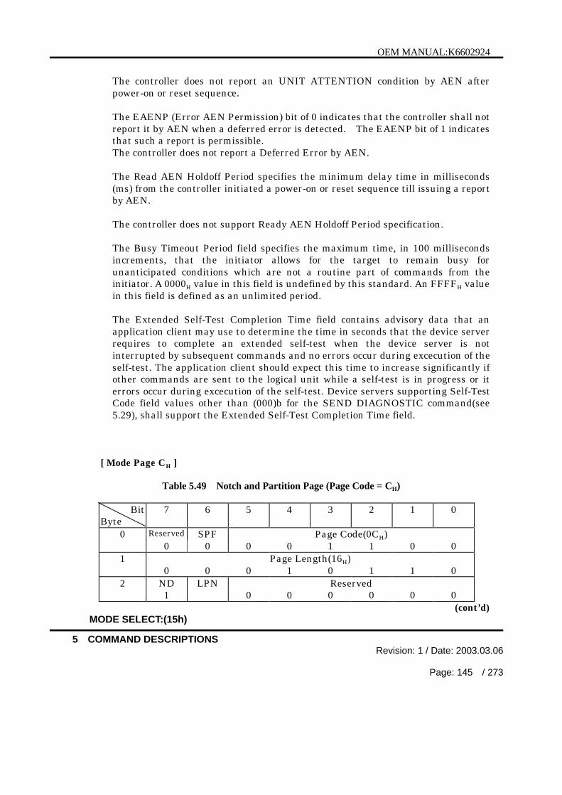
OEM MANUAL:K6602924
5 COMMAND DESCRIPTIONSRevision: 1 / Date: 2003.03.06
Page: 145 / 273
The controller does not report an UNIT ATTENTION condition by AEN afterpower-on or reset sequence.
The EAENP (Error AEN Permission) bit of 0 indicates that the controller shall notreport it by AEN when a deferred error is detected. The EAENP bit of 1 indicatesthat such a report is permissible.The controller does not report a Deferred Error by AEN.
The Read AEN Holdoff Period specifies the minimum delay time in milliseconds(ms) from the controller initiated a power-on or reset sequence till issuing a reportby AEN.
The controller does not support Ready AEN Holdoff Period specification.
The Busy Timeout Period field specifies the maximum time, in 100 millisecondsincrements, that the initiator allows for the target to remain busy forunanticipated conditions which are not a routine part of commands from theinitiator. A 0000H value in this field is undefined by this standard. An FFFFH valuein this field is defined as an unlimited period.
The Extended Self-Test Completion Time field contains advisory data that anapplication client may use to determine the time in seconds that the device serverrequires to complete an extended self-test when the device server is notinterrupted by subsequent commands and no errors occur during excecution of theself-test. The application client should expect this time to increase significantly ifother commands are sent to the logical unit while a self-test is in progress or iterrors occur during excecution of the self-test. Device servers supporting Self-TestCode field values other than (000)b for the SEND DIAGNOSTIC command(see5.29), shall support the Extended Self-Test Completion Time field.
[ Mode Page CH ]
Table 5.49 Notch and Partition Page (Page Code = CH)
BitByte
7 6 5 4 3 2 1 0
0 Reserved SPF Page Code(0CH)0 0 0 0 1 1 0 0
1 Page Length(16H)0 0 0 1 0 1 1 0
2 ND LPN Reserved1 0 0 0 0 0 0
(cont’d)MODE SELECT:(15h)

OEM MANUAL:K6602924
5 COMMAND DESCRIPTIONSRevision: 1 / Date: 2003.03.06
Page: 146 / 273
Table 5.49 Notch and Partition Page (Page Code = CH) (cont’d)
3 Reserved0 0 0 0 0 0 0 0
4 Maximum Number of Notches (MSB)
5 Maximum Number of Notches (LSB)
6 Active Notch (MSB)
7 Active Notch (LSB)
8 Starting Boundary (MSB)|11 Starting Boundary (LSB)
12 Ending Boundary (MSB)|15 Ending Boundary (LSB)
16 Pages Notched (MSB)|23 Pages Notched (LSB)
This page specifies the parameters for direct-access devices supporting a variablenumber of blocks per cylinder. Each section of the drive with a different numberof blocks per cylinder is referred to as a Notch. Each Notch will span a set ofconsecutive logical blocks on the logical drive. The Notches will not overlap, andno logical block will be excluded from a Notch.
The ND (Notched Drive) bit specifies whether or not the drive is notched. A NDbit of 0 indicates that the device is not notched and that all other parameters inthis page shall be returned as zero by the controller. A ND bit of 1 indicates thatthe device is notched. For each supported active notch value, this page definesthe starting and ending boundaries of the notch.In case of ND = 1, the following description for the Maximum Number of Notches,Active Notch, Starting Boundary, Ending Boundary and Pages Notched isapplied.
The LPN (Logical or Physical Notch) bit specifies whether the Starting Boundaryand the Ending Boundary fields reported by the MODE SENSE commandindicates physical parameter(cylinder number and head number) or logical blockaddress.
MODE SELECT:(15h)
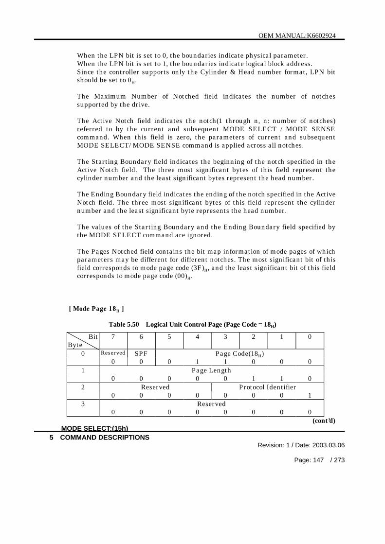
OEM MANUAL:K6602924
5 COMMAND DESCRIPTIONSRevision: 1 / Date: 2003.03.06
Page: 147 / 273
When the LPN bit is set to 0, the boundaries indicate physical parameter.When the LPN bit is set to 1, the boundaries indicate logical block address.Since the controller supports only the Cylinder & Head number format, LPN bitshould be set to 0H.
The Maximum Number of Notched field indicates the number of notchessupported by the drive.
The Active Notch field indicates the notch(1 through n, n: number of notches)referred to by the current and subsequent MODE SELECT / MODE SENSEcommand. When this field is zero, the parameters of current and subsequentMODE SELECT/ MODE SENSE command is applied across all notches.
The Starting Boundary field indicates the beginning of the notch specified in theActive Notch field. The three most significant bytes of this field represent thecylinder number and the least significant bytes represent the head number.
The Ending Boundary field indicates the ending of the notch specified in the ActiveNotch field. The three most significant bytes of this field represent the cylindernumber and the least significant byte represents the head number.
The values of the Starting Boundary and the Ending Boundary field specified bythe MODE SELECT command are ignored.
The Pages Notched field contains the bit map information of mode pages of whichparameters may be different for different notches. The most significant bit of thisfield corresponds to mode page code (3F)H, and the least significant bit of this fieldcorresponds to mode page code (00)H.
[ Mode Page 18H ]
Table 5.50 Logical Unit Control Page (Page Code = 18H)
BitByte
7 6 5 4 3 2 1 0
0 Reserved SPF Page Code(18H)0 0 0 1 1 0 0 0
1 Page Length0 0 0 0 0 1 1 0
2 Reserved Protocol Identifier0 0 0 0 0 0 0 1
3 Reserved0 0 0 0 0 0 0 0
(cont’d)MODE SELECT:(15h)
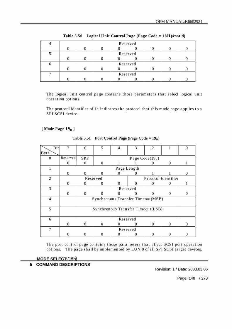
OEM MANUAL:K6602924
5 COMMAND DESCRIPTIONSRevision: 1 / Date: 2003.03.06
Page: 148 / 273
Table 5.50 Logical Unit Control Page (Page Code = 18H)(cont’d)
4 Reserved0 0 0 0 0 0 0 0
5 Reserved0 0 0 0 0 0 0 0
6 Reserved0 0 0 0 0 0 0 0
7 Reserved0 0 0 0 0 0 0 0
The logical unit control page contains those parameters that select logical unitoperation options.
The protocol identifier of 1h indicates the protocol that this mode page applies to aSPI SCSI device.
[ Mode Page 19H ]
Table 5.51 Port Control Page (Page Code = 19H)
BitByte
7 6 5 4 3 2 1 0
0 Reserved SPF Page Code(19H)0 0 0 1 1 0 0 1
1 Page Length0 0 0 0 0 1 1 0
2 Reserved Protocol Identifier0 0 0 0 0 0 0 1
3 Reserved0 0 0 0 0 0 0 0
4 Synchronous Transfer Timeout(MSB)
5 Synchronous Transfer Timeout(LSB)
6 Reserved0 0 0 0 0 0 0 0
7 Reserved0 0 0 0 0 0 0 0
The port control page contains those parameters that affect SCSI port operationoptions. The page shall be implemented by LUN 0 of all SPI SCSI target devices.
MODE SELECT:(15h)

OEM MANUAL:K6602924
5 COMMAND DESCRIPTIONSRevision: 1 / Date: 2003.03.06
Page: 149 / 273
The page shall not be implemented by logical units other than LUN 0. Theimplementation of any bit and its associated functions is optional.
The protocol identifier of 1h indicates the protocol that this mode page applies to aSPI SCSI device.
The synchronous transfer timeout field indicates the maximum amount of time in1 ms increments that the controller shall wait before generating an error by doingan unexpected bus free.The controller shall only go to a BUS FREE phase if one of the following eventscauses the timer, once started, to not reset or reload before expiring.
a) If there is a REQ transition when there are no outstanding REQs waiting foran ACK then load and start the timer.
b) If there is a REQ transition when there are any outstanding REQs waiting foran ACK then there is no effect on the timer.
c) If there is an ACK transition when there are outstanding REQs waiting for anACK then load and start the timer.
d) If after an ACK transition there are no outstanding REQs waiting for an ACKthen stop the timer.
A synchronous transfer timeout field value of 0000H indicates that the function isdisabled. A value of FFFFH indicates an unlimited period.
[ Mode Page 19H Sub Page 01H ]
Table 5.52 Margin Control Sub Page (Page Code = 19H, Sub Page Code = 01H)
BitByte
7 6 5 4 3 2 1 0
0 Reserved SPF Page Code(19H)0 1 0 1 1 0 0 1
1 Sub Page Code(01H)0 0 0 0 0 0 0 1
2 Page Length(MSB)0 0 0 0 0 0 0 0
3 Page Length(LSB)0 0 0 1 0 0 1 0
(cont’d)
MODE SELECT:(15h)

OEM MANUAL:K6602924
5 COMMAND DESCRIPTIONSRevision: 1 / Date: 2003.03.06
Page: 150 / 273
Table 5.52 Margin Control Sub Page (Page Code = 19H, Sub Page Code = 01H)(cont’d)
4 Reserved0 0 0 0 0 0 0 0
5 Reserved Protocol Identifier0 0 0 0 0 0 0 1
6 Reserved0 0 0 0 0 0 0 0
7 Driver Strength Reserved0 0 0 0
8 Driver Asymmetry Driver Precompensation
9 Driver Slew Rate Reserved0 0 0 0
10 Reserved0 0 0 0 0 0 0 0
11 Reserved0 0 0 0 0 0 0 0
12 Reserved0 0 0 0 0 0 0 0
13 Vendor Specification0 0 0 0 0 0 0 0
14 Reserved0 0 0 0 0 0 0 0
15 Reserved0 0 0 0 0 0 0 0
16 Reserved0 0 0 0 0 0 0 0
17 Reserved0 0 0 0 0 0 0 0
18 Reserved0 0 0 0 0 0 0 0
19 Reserved0 0 0 0 0 0 0 0
20 Reserved0 0 0 0 0 0 0 0
21 Reserved0 0 0 0 0 0 0 0
The margin control subpage (see Table 5.52) contains parameters that set andreport margin control values for usage between the host computer/controller pairon subsequent synchronous and paced transfers.
MODE SELECT:(15h)

OEM MANUAL:K6602924
5 COMMAND DESCRIPTIONSRevision: 1 / Date: 2003.03.06
Page: 151 / 273
The subpage code field indicates which subpage is being accessed. If the SubpageCode field is zero the controller shall return a CHECK CONDITION status. Thesense key shall be set to ILLEGAL REQUEST and the additional sense code set toILLEGAL FIELD IN PARAMETER LIST.
The protocol identifier of 1h indicates the protocol that this mode page applies to aSPI SCSI device.
The driver strength field indicates the relative amount of driver source currentused by the driver. The driver strength field affects both the strong and weakdrives.
The driver precompensation field indicates the relative difference between theweak driver and the strong driver amplitudes when precompensation is enabled. Alarger value indicates a larger difference between the weak and strongamplitudes.
The driver asymmentry field indicates the relative difference between theamplitudes of asserted and negated signals launched from the driver. A largervalue indicates a relatively stronger asserted signal compared to the negatedsignal.
The driver slew rate field indicates the relative difference between the assertionand negation magnitudes divided by the rise or fall time. A larger value indicatesa faster slew rate.
The default value of each margin control field should be 0000b.
[ Mode Page 19H Sub Page 02H ]
Table 5.53 Saved Training Configuration SubPage (Page Code = 19H, SubPage Code = 02H)Bit
Byte7 6 5 4 3 2 1 0
0 Reserved SPF Page Code(19H)0 1 0 1 1 0 0 1
1 Sub Page Code(02H)0 0 0 0 0 0 1 0
2 Page Length(MSB)0 0 0 0 0 0 0 0
3 Page Length(LSB)1 1 1 0 0 1 1 0
(cont’d)
MODE SELECT:(15h)

OEM MANUAL:K6602924
5 COMMAND DESCRIPTIONSRevision: 1 / Date: 2003.03.06
Page: 152 / 273
Table 5.53 Saved Training Configuration SubPage (Page Code = 19H, SubPage Code =02H)(cont’d)
4 Reserved0 0 0 0 0 0 0 0
5 Reserved Protocol Identifier0 0 0 0 0 0 0 1
6 – 9 Reserved10-13 DB(0) Value14-17 DB(1) Value18-21 DB(2) Value22-25 DB(3) Value26-29 DB(4) Value30-33 DB(5) Value34-37 DB(6) Value38-41 DB(7) Value42-45 DB(8) Value46-49 DB(9) Value50-53 DB(10) Value54-57 DB(11) Value58-61 DB(12) Value62-65 DB(13) Value66-69 DB(14) Value70-73 DB(15) Value74-77 P_CRCA Value78-81 P1 Value82-85 BSY Value86-89 SEL Value90-93 RST Value94-97 REQ Value98-101 ACK Value102-105 ATN Value106-109 C/D Value110-113 I/O Value114-117 MSG Value118-233 Reserved
The saved training configuration values sub page is used to report the SCSIdevice’s saved training configuration values. These vendor specific values aremaintained by the SCSI device when the retain training information option isenabled (see 3.2.3). The fields are listed in Table 5.53however the content of thefields is vendor specific.
MODE SELECT:(15h)

OEM MANUAL:K6602924
5 COMMAND DESCRIPTIONSRevision: 1 / Date: 2003.03.06
Page: 153 / 273
Only values for the current I_T nexus are reported.
The protocol identifier of 1h indicates the protocol that this mode page applies to aSPI SCSI device.
The controller does not support BSY Value, SEL Value, RST Value, ATN Value,C/D Value, I/O Value, and MSG Value.
[ Mode Page 19H Sub Page 03H ]
Table 5.54 Negotiated Setting Sub Page (Page Code = 19H, Sub Page Code = 03H)
BitByte
7 6 5 4 3 2 1 0
0 Reserved SPF Page Code(19H)0 1 0 1 1 0 0 1
1 Sub Page Code(03H)0 0 0 0 0 0 1 1
2 Page Length(MSB)0 0 0 0 0 0 0 0
3 Page Length(LSB)0 0 0 0 1 0 1 0
4 Reserved0 0 0 0 0 0 0 0
5 Reserved Protocol Identifier0 0 0 0 0 0 0 1
6 Transfer Period Factor
7 Reserved0 0 0 0 0 0 0 0
8 REQ/ACK Offset
9 Transfer Width Exponent
10 Reserved Protocol Option Bits0
11 Reserved Transceiver Mode Sent Received
0 0 0 0 PCOMP_EN PCOMP_EN
12 Reserved0 0 0 0 0 0 0 0
13 Reserved0 0 0 0 0 0 0 0
MODE SELECT:(15h)

OEM MANUAL:K6602924
5 COMMAND DESCRIPTIONSRevision: 1 / Date: 2003.03.06
Page: 154 / 273
The negotiated settings sub page, shown in Table 5.54, is used to report thenegotiated settings of the controller for the current I_T nexus.
The protocol identifier of 1h indicates the protocol that this mode page applies to aSPI SCSI device.
The transfer period factor field indicates the negotiated transfer period for thecurrent I_T nexus.
The REQ/ACK offset field indicates the negotiated REQ/ACK offset for the currentI_T nexus.
The transfer width exponent field indicates the negotiated transfer widthexponent for the current I_T nexus.
The protocol option bits field contain the negotiated protocol options for thecurrent I_T nexus.
The received PCOMP_EN bit contains the value of the PCOMP_EN bit received bythe controller for the current I_T nexus.
The sent PCOMP_EN bit contains the value of the PCOMP_EN bit sent by thecontroller for the current I_T nexus.
The transceiver mode field specifies the current bus mode of the controller asdefined in Table 5.55.
Table 5.55 Bus Mode
Code Bus Mode00b Unknown01b Single ended10b Low Voltage Differential11b High Voltage Differential
MODE SELECT:(15h)

OEM MANUAL:K6602924
5 COMMAND DESCRIPTIONSRevision: 1 / Date: 2003.03.06
Page: 155 / 273
[ Mode Page 19H Sub Page 04H ]
Table 5.56 Report Transfer Capabilities Sub Page (Page Code = 19H, Sub Page Code = 04H)
BitByte
7 6 5 4 3 2 1 0
0 Reserved SPF Page Code(19H)0 1 0 1 1 0 0 1
1 Sub Page Code(04H)0 0 0 0 0 1 0 0
2 Page Length(MSB)0 0 0 0 0 0 0 0
3 Page Length(LSB)0 0 0 0 1 0 1 0
4 Reserved0 0 0 0 0 0 0 0
5 Reserved Protocol Identifier0 0 0 0 0 0 0 1
6 Minimum Transfer Period Factor
7 Reserved0 0 0 0 0 0 0 0
8 Maximum REQ/ACK Offset
9 Maximum Transfer Width Exponent
10 Protocol Options Bits Supported
11 Reserved0 0 0 0 0 0 0 0
12 Reserved0 0 0 0 0 0 0 0
13 Reserved0 0 0 0 0 0 0 0
The negotiated settings sub page, shown in Table 5.56, is used to report thetransfer capabilities for the controller. The values in this sub page are notchangeable via a MODE SELECT command.
The protocol identifier of 1h indicates the protocol that this mode page applies to aSPI SCSI device.
MODE SELECT:(15h)

OEM MANUAL:K6602924
5 COMMAND DESCRIPTIONSRevision: 1 / Date: 2003.03.06
Page: 156 / 273
The Minimum Transfer Period Factor field shall be set to the smallest value of thetransfer period factor supported by the controller.
The Maximum REQ/ACK Offset shall be set to the largest value of the REQ/ACKoffset supported by the controller.
The Maximum Transfer Width Exponent shall be set to the largest value of thetransfer width exponent supported by the controller.
The controller shall set the bits in the Protocol Options Bits Supported fieldindicate the protocol options supported by the controller. (see Table 5.57)
Table 5.57 Protocol Options Bits
Bit Name7 PCOMP_EN6 RTI5 RD_STRM4 WR_FLOW3 HOLD_MCS2 QAS_REQ1 DT_REQ0 IU_REQ
MODE SELECT:(15h)

OEM MANUAL:K6602924
5 COMMAND DESCRIPTIONSRevision: 1 / Date: 2003.03.06
Page: 157 / 273
[ Mode Page 1AH ]
Table 5.58 Power Condition Control Page (Page Code = 1AH)
BitByte
7 6 5 4 3 2 1 0
0 Reserved SPF Page Code(1AH)0 0 0 1 1 0 1 0
1 Page Length0 0 0 0 1 0 1 0
2 Reserved0 0 0 0 0 0 0 0
3 Reserved Idle Standby0 0 0 0 0 0
4 (MSB)| Idle Condition Timer7 (LSB)8 (MSB)| Standby Condition Timer11 (LSB)
An Idle bit of one indicates that the logical unit shall use the idle condition timerfield to determine the length of inactivity time to wait before entering the idlecondition. An Idle bit of zero indicates that the logical unit shall not enter the idlecondition.Since the controller does not support Idle bit, this bit ignore.
A Standby bit of one indicates that the logical unit shall use the standby conditiontimer field to determine the length of inactivity time to wait before entering thestandby condition. A standby bit of zero indicates that the logical unit shall notenter the standby condition.Since the controller does not support Standby bit, this bit ignore.
The idle condition timer field indicates the inactivity time in 100 millisecondincrements that the logical unit shall wait before entering the idle condition.Since the controller does not support idle condition timer field, this field ignore.
If the idle bit is one, a value of zero in the idle condition timer indicates the logicalunit shall enter the idle condition on completion of any command.
MODE SELECT:(15h)
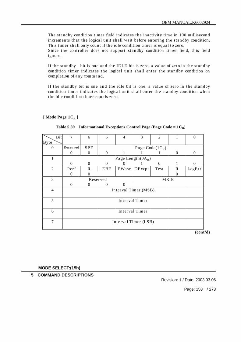
OEM MANUAL:K6602924
5 COMMAND DESCRIPTIONSRevision: 1 / Date: 2003.03.06
Page: 158 / 273
The standby condition timer field indicates the inactivity time in 100 millisecondincrements that the logical unit shall wait before entering the standby condition.This timer shall only count if the idle condition timer is equal to zero.Since the controller does not support standby condition timer field, this fieldignore.
If the standby bit is one and the IDLE bit is zero, a value of zero in the standbycondition timer indicates the logical unit shall enter the standby condition oncompletion of any command.
If the standby bit is one and the idle bit is one, a value of zero in the standbycondition timer indicates the logical unit shall enter the standby condition whenthe idle condition timer equals zero.
[ Mode Page 1CH ]
Table 5.59 Informational Exceptions Control Page (Page Code = 1CH)
BitByte
7 6 5 4 3 2 1 0
0 Reserved SPF Page Code(1CH)0 0 0 1 1 1 0 0
1 Page Length(0AH)0 0 0 0 1 0 1 0
2 Perf R EBF EWasc DExcpt Test R LogErr0 0 0
3 Reserved MRIE0 0 0 0
4 Interval Timer (MSB)
5 Interval Timer
6 Interval Timer
7 Interval Timer (LSB)
(cont’d)
MODE SELECT:(15h)

OEM MANUAL:K6602924
5 COMMAND DESCRIPTIONSRevision: 1 / Date: 2003.03.06
Page: 159 / 273
Table 5.59 Informational Exceptions Control Page (Page Code = 1CH)(cont’d)
8 Report Count (MSB)
9 Report Count
10 Report Count
11 Report Count (LSB)
The informational exceptions control page defines the methods to control thereporting of specific informational exception conditions in the controller.
The informational exception conditions occur as the result of exceeding thethreshold of informational exceptions in the controller.
The informational exception conditions occur asynchronously to any commandsissued by the host computer.
An EBF (Enable Background Function) bit of one indicates the target shall enablebackground functions. An EBF bit of zero indicates the target shall disable thefunctions.Since the controller does not support EBF bit, this bit ignore.
A Perf (Performance) bit of 0 allows the informational exception operations tocause the delays of command operation from the host computer.
A Perf bit of 1 does not allow the informational exception operations to cause thedelays of command operation from the host computer.Since the controller does not support Perf bit, this bit is ignored.
A EWasc(Enable Warning) bit of zero indicates that the controller does not reportthe warning.A EWasc bit of one indicates that the controller reports warning.The method forreporting the warning depends on the MRIE field setting.Since the conroller does not support EWasc bit, this bit is ignored.
A DExcpt (Disable Exception control) bit of 0 indicates that information exceptionoperations are enabled. The method of reporting information exceptionconditions is determined from the MRIE (Method of Reporting InformationalExceptions; see Table 5.60) field when the DExcpt bit is set to 0.
MODE SELECT:(15h)

OEM MANUAL:K6602924
5 COMMAND DESCRIPTIONSRevision: 1 / Date: 2003.03.06
Page: 160 / 273
A DExcpt bit of 1 indicates that the informational exception operations aredisabled.
A Test bit of 1 indicates that the controller reports the results of informationalexception test at each interval time ( if the DExcpt bit = 0). The conditions arereported with an additional sense code and an additional sense code qualifier of 5DFFH.A Test bit of 0 indicates that the controller does not report the results ofinformational exception test.The Test bit can’t be saved regardless of a PS bit value.
The LogErr (Log errors) bit of 1 indicates the controller logs the informationalexception conditions. The LogErr bit of 0 indicates the controller does not log theinformational exception conditions.
The MRIE field defines the methods that the controller reports the informationalexception conditions.
Table 5.60 Method of Reporting Informational Exceptions field
MRIE Description0 h The controller does not report informational exceptions
conditions.2 h Generate unit attention:
The controller reports informational exceptions conditions byreturning CHECK CONDITION status on the commands. Thecontroller sets a sense key to UNIT ATTENTION and additionalsense code to the cause of informational exception condition.
3 h Conditionally generate recovered error :The controller reports informational exception conditions byreturning CHECK CONDITION status on the commands inaccordance with the value of the PER (Post Error) bit in modeparameter (Error recovery parameters). The controller sets asense key to RECOVERED ERROR and additional sense code tothe cause of informational exception condition.
(cont’d)
MODE SELECT:(15h)

OEM MANUAL:K6602924
5 COMMAND DESCRIPTIONSRevision: 1 / Date: 2003.03.06
Page: 161 / 273
Table 5.60 Method of Reporting Informational Exceptions field (cont’d)
4 h Unconditionally generate recovered error :The controller reports informational exceptions conditions byreturning CHECK CONDITION status on the commands otherthan(Reassign Blocks, Request Sense, Inquiry, Start/Stop Unit,Mode Select, Report Luns) in regardless of the value of the PER(Post Error) bit in mode parameter (Error recovery parameters).The controller sets a sense key to RECOVERED ERROR andadditional sense code to the cause of informational exceptioncondition.
6 h Only report informational exception condition on request :The controller preserves the informational exception informationin it. The host computer polls the controller by issuingREQUEST SENSE command to get informational exceptioninformation. The controller sets a sense key to NO SENSE andadditional sense code to the cause of informational exceptioncondition.
This controller does not support other than the value in Table 5.60.
The Interval Timer field indicates the period in 100 millisecond increments forreporting that an informational exception condition has occurred.The Interval Timer field of 0 indicates that the controller shall only report theinformational exception condition one time.The Interval Timer field of FFFFFFFFH indicates the timer interval is the valuecreated by the controller (approximately 10 minutes) .
The Report Count field indicates the number of times to report an informationalexception condition to the host computer.The Report Count field of 0 indicates that there is no limit on the number of timesthe controller reports an informational exception condition.
Note : If Interval Timer and Report Count values set to other than the supportedvalues are specified the controller ignores these values. The controller doesnot consider this condition as an error.
If the MRIE field has a value of 6, then the interval timer and report count areignored.
MODE SELECT:(15h)

OEM MANUAL:K6602924
5 COMMAND DESCRIPTIONSRevision: 1 / Date: 2003.03.06
Page: 162 / 273
5.6 MODE SELECT (10):(55H)
BitByte
7 6 5 4 3 2 1 0
0 Operation Code (55H)0 1 0 1 0 1 0 1
1 Logical Unit Number PF Reserved SP0 0 0
2 Reserved0 0 0 0 0 0 0 0
3 Reserved0 0 0 0 0 0 0 0
4 Reserved0 0 0 0 0 0 0 0
5 Reserved0 0 0 0 0 0 0 0
6 Reserved0 0 0 0 0 0 0 0
7 Parameter List Length (MSB)
8 Parameter List Length (LSB)
9 Vendor Unique Reserved Flag Link0 0 0 0 0 0
The MODE SELECT (10) command is the same as the MODE SELECT commandexcept that the MODE SELECT (10) command has 2-byte length of Parameter ListLength and 8-byte length of MODE SELECT Header as follows.
Refer to item 5.5, MODE SELECT command in detail.
MODE SELECT (10):(55h)

OEM MANUAL:K6602924
5 COMMAND DESCRIPTIONSRevision: 1 / Date: 2003.03.06
Page: 163 / 273
Table 5.61 MODE SELECT (10) Header
BitByte
7 6 5 4 3 2 1 0
0 Reserved0 0 0 0 0 0 0 0
1 Reserved0 0 0 0 0 0 0 0
2 Medium Type0 0 0 0 0 0 0 0
3 WP Reserved DPOFUA Reserved0 0 0 0 0 0
4 Reserved0 0 0 0 0 0 0 0
5 Reserved0 0 0 0 0 0 0 0
6 Block Descriptor Length (MSB)
7 Block Descriptor Length (LSB)
MODE SELECT (10):(55h)

OEM MANUAL:K6602924
5 COMMAND DESCRIPTIONSRevision: 1 / Date: 2003.03.06
Page: 164 / 273
5.7 MODE SENSE:(1AH)
BitByte
7 6 5 4 3 2 1 0
0 Operation Code (1AH)0 0 0 1 1 0 1 0
1 Logical Unit Number R DBD Reserved0 0 0 0
2 PC Page Code
3 Sub Page Code
4 Allocation Length
5 Vendor Unique Reserved Flag Link0 0 0 0 0 0
The MODE SENSE command provides a means for the controller to report itsmedium, logical unit, or controller parameters to the host computer.It is a complementary command to the MODE SELECT command (See 5.5).
The DBD (Disable Block Descriptor) bit of 0 indicates the controller transfers theBlock Descriptor. The DBD bit of 1 indicates the controller does not transfer theBlock Descriptor.
The PC (Page Control) field defines the type (one of those listed below) of theparameter values to be returned.
Bit 7 Bit 60 0 Current values0 1 Changeable values1 0 Default values1 1 Saved values
The controller sets the page parameter fields and bits to values of the specified typeand reports them to host computer.
[ Current values ]A current value takes on one of the following values :
- The value that is set in the last successfully completed MODE SELECTcommand. The default value is taken for unchangeable values.
- The saved value (if no MODE SELECT command has been issued since the lastpower on).
- The default value if saved value is not available.MODE SENSE:(1Ah)
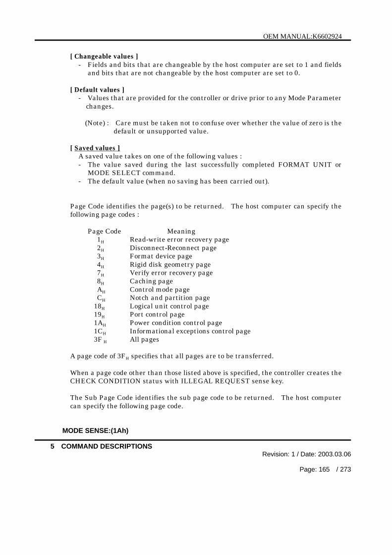
OEM MANUAL:K6602924
5 COMMAND DESCRIPTIONSRevision: 1 / Date: 2003.03.06
Page: 165 / 273
[ Changeable values ]- Fields and bits that are changeable by the host computer are set to 1 and fields
and bits that are not changeable by the host computer are set to 0.
[ Default values ]- Values that are provided for the controller or drive prior to any Mode Parameter
changes.
(Note) : Care must be taken not to confuse over whether the value of zero is thedefault or unsupported value.
[ Saved values ]A saved value takes on one of the following values :- The value saved during the last successfully completed FORMAT UNIT or
MODE SELECT command.- The default value (when no saving has been carried out).
Page Code identifies the page(s) to be returned. The host computer can specify thefollowing page codes :
Page Code Meaning1H Read-write error recovery page2H Disconnect-Reconnect page3H Format device page4H Rigid disk geometry page7H Verify error recovery page8H Caching pageAH Control mode pageCH Notch and partition page
18H Logical unit control page19H Port control page1AH Power condition control page1CH Informational exceptions control page3F H All pages
A page code of 3FH specifies that all pages are to be transferred.
When a page code other than those listed above is specified, the controller creates theCHECK CONDITION status with ILLEGAL REQUEST sense key.
The Sub Page Code identifies the sub page code to be returned. The host computercan specify the following page code.
MODE SENSE:(1Ah)

OEM MANUAL:K6602924
5 COMMAND DESCRIPTIONSRevision: 1 / Date: 2003.03.06
Page: 166 / 273
Page Code Sub Page Code Meaning19H 01H Margin control page19H 02H Saved training configuration page19H 03H Negotiated setting page19H 04H Report Transfer Capabilities page
A sub page code of FFH specifies that all sub pages and page 19H are to be transferred
When a page code other than those listed above is specified, the controller creates theCHECK CONDITION status with ILLEGAL REQUEST sense key.
The Allocation Length field specifies the number of bytes that the host computer hasallocated for the Mode Sense data to be returned. An allocation length of 0 specifiesthat no Mode Sense data is to be transferred.
This condition must not be considered as an error. Any other allocation length valuespecifies the maximum number of bytes that can be transferred. The controllerterminates the Data In
phase when the number of bytes specified in the Allocation Length field have beentransferred or when all available Mode Sense data have been transferred to the hostcomputer, whichever is less.
The Mode Sense Data consists of a 4-byte header, followed by eight bytes of a blockdescriptor, followed by zero or more page descriptors.
Table 5.62 Mode Sense Data
BitByte
7 6 5 4 3 2 1 0
MODE SENSE Header
0 Sense Data Length
1 Medium Type0 0 0 0 0 0 0 0
2 WP Reserved DPOFUA Reserved0 0 0 0 0 0
3 Block Descriptor Length0 0 0 0 1 0 0 0
(cont’d)
MODE SENSE:(1Ah)
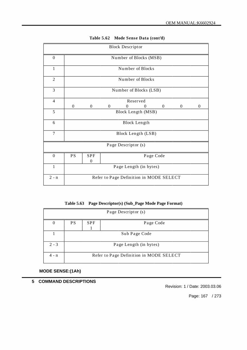
OEM MANUAL:K6602924
5 COMMAND DESCRIPTIONSRevision: 1 / Date: 2003.03.06
Page: 167 / 273
Table 5.62 Mode Sense Data (cont’d)
Block Descriptor
0 Number of Blocks (MSB)
1 Number of Blocks
2 Number of Blocks
3 Number of Blocks (LSB)
4 Reserved0 0 0 0 0 0 0 0
5 Block Length (MSB)
6 Block Length
7 Block Length (LSB)
Page Descriptor (s)
0 PS SPF Page Code0
1 Page Length (in bytes)
2 - n Refer to Page Definition in MODE SELECT
Table 5.63 Page Descriptor(s) (Sub_Page Mode Page Format)
Page Descriptor (s)
0 PS SPF Page Code1
1 Sub Page Code
2 - 3 Page Length (in bytes)
4 - n Refer to Page Definition in MODE SELECT
MODE SENSE:(1Ah)

OEM MANUAL:K6602924
5 COMMAND DESCRIPTIONSRevision: 1 / Date: 2003.03.06
Page: 168 / 273
The Sense Data Length field specifies the length in bytes of the following Mode Sensedata that is available to be transferred during the Data In phase. It does notinclude the length of the Sense Data Length Field itself. The Sense Data Lengthfield is loaded with one of the following values according to the setting of the pagecode in the CDB, irrespective of the value specified in the Allocation Length field inthe CDB :
Table 5.64 Sense Data Length
Page Code Sense Data Length1H 17H
2H 1BH
3H 23H
4H 23H
7H 17H
8H 1FH
AH 17H
CH 23H
18H 13H
19H 13H
1AH 17H
1CH 17H
3FH C3H
The Medium Type field is loaded with code 00H and identifies the default mediumtype (the type of the currently mounted medium).
The WP (Write Protected) bit, when set to 0, indicates that the medium is enabled forwrite operations.A WP bit of 1 indicates that the medium is protected against write operations.
A DPOFUA bit of 1 indicates that the DPO bit and FUA bit for READ/WRITEcommand are supported.
The Block Descriptor Length field specifies the length in bytes of the block descriptor.Since there is only one block descriptor, this field must always be set to 08H.
The block descriptor contains the number of blocks and the block length andindicates the accessible area from the host for a logical unit.
The Number of Blocks field specifies the number of logical blocks on the medium thatcorresponds to the block length in the block descriptor.
MODE SENSE:(1Ah)

OEM MANUAL:K6602924
5 COMMAND DESCRIPTIONSRevision: 1 / Date: 2003.03.06
Page: 169 / 273
Note : The host computer can obtain the number of logical blocks by adding 1 tothe maximum logical block address that is returned with the READCAPACITY command (see 5.14).
The Block Length field specifies the length in bytes of the logical blocks on themedium.Please refer to “Product Specifications” for the information of the eligible logicallength values.
The page descriptors specify the page data requested by the host computer. Fordetails on the pages, see the page definitions given in the MODE SELECT commanddescription (see 5.5).
The PS (Parameter Savable) bit of 0 indicates that the controller cannot save thespecified page. This bit of 1 indicates that the controller can save the specified page.
Each page descriptor lists the default and changeable values that the SCSI controllerreturns to the host computer. The default value XXH indicates the case of thedifferent values (e.g. number of heads) at each product.
MODE SENSE:(1Ah)

OEM MANUAL:K6602924
5 COMMAND DESCRIPTIONSRevision: 1 / Date: 2003.03.06
Page: 170 / 273
[ Mode Page 1H ]
Table 5.65 Mode Page 1H Descriptor Value
Read-Write Error Recovery Page (Page 01H)Byte Bit Meaning Default
ValuesChangeable
ValuesCurrent/Saved
Values0 81H 81H 81H
7 PS 1 1 16 SPF 0 0 0
5-0 Page Code 01H 01H 01H
1 Page Length 0AH 0AH 0AH
2 C8H FFH XXH
7 AWRE 1 1 0/16 ARRE 1 1 0/15 TB 0 1 0/14 RC 0 1 0/13 EER 1 1 0/12 PER 0 1 0/11 DTE 0 1 0/10 DCR 0 1 0/1
3 Read Retry Count 80H FFH XXH
4 Correction Span A0H FFH XXH
5 Head Offset Count 00H FFH XXH
6 Data Strobe Count 00H FFH XXH
7 Reserved 00H 00H 00H
8 Write Retry Count 80H FFH XXH
9 Reserved 00H 00H 00H
10 Recovery 0BH FFH XXH
11 Time Limit B8H FFH XXH
MODE SENSE:(1Ah)

OEM MANUAL:K6602924
5 COMMAND DESCRIPTIONSRevision: 1 / Date: 2003.03.06
Page: 171 / 273
[ Mode Page 2H ]
Table 5.66 Mode Page 2H Descriptor Value
Disconnect - Reconnect Page (Page 02H)Byte Bit Meaning Default
ValuesChangeable
ValuesCurrent/Saved
Values0 82H 82H 82H
7 PS 1 1 16 SPF 0 0 0
5-0 Page Code 02H 02H 02H
1 Page Length 0EH 0EH 0EH
2 Buffer Full Ratio 00H FFH XXH
3 Buffer Empty Ratio 80H FFH XXH
45
Bus InactivityLimit
00H
00H
FFH
FFH
XXH
XXH
6 Disconnect Time 00H FFH XXH
7 Limit 00H FFH XXH
89
Connect TimeLimit
00H
00H
FFH
FFH
XXH
XXH
10 Maximum 00H FFH XXH
11 Burst Size 00H FFH XXH
12 10H 7FH XXH
7 Reserved 0H 0H 0H
6-4 Fair Arbitration 1H 7H 0/1H
3 DIMM 0H 1H 0/1H
2-0 DTDC 0H 7H 0H/1H/3H
13 Reserved 00H 00H 00H
14 Reserved 00H 00H 00H
15 Reserved 00H 00H 00H
MODE SENSE:(1Ah)

OEM MANUAL:K6602924
5 COMMAND DESCRIPTIONSRevision: 1 / Date: 2003.03.06
Page: 172 / 273
[ Mode Page 3H ]
Table 5.67 Mode Page 3H Descriptor Value
Format Device Page (Page 03H)Byte Bit Meaning Default
ValuesChangeable
ValuesCurrent/Saved
Values0 83H 83H 83H
7 PS 1 1 16 SPF 0 0 0
5-0 Page Code 03H 03H 03H
1 Page Length 16H 16H 16H
23
Tracks per Zone XXH
XXH
00H
00H
XXH
XXH
4 Alternate Sectors XXH 00H XXH
5 per Zone XXH 00H XXH
6 Alternate Tracks 00H 00H 00H
7 per Zone XXH 00H XXH
8 Alternate Tracks XXH 00H XXH
9 per Volume XXH 00H XXH
1011
Sectors per Track XXH
XXH
00H
00H
XXH
XXH
12 Data Bytes per 02H FFH XXH
13 Physical Sector 00H FFH XXH
1415
Interleave 00H
01H
00H
00H
00H
01H
1617
Track Skew Factor 00H
XXH
00H
00H
00H
XXH
18 Cylinder Skew 00H 00H 00H
19 Factor XXH 00H XXH
20 40H 00H 40H
7 SSEC 0 0 06 HSEC 1 0 15 RMB 0 0 04 SURF 0 0 03 INS 0 0 0
2-0 Reserved 0H 0H 0H
21 Reserved 00H 00H 00H
22 Reserved 00H 00H 00H
23 Reserved 00H 00H 00H
MODE SENSE:(1Ah)

OEM MANUAL:K6602924
5 COMMAND DESCRIPTIONSRevision: 1 / Date: 2003.03.06
Page: 173 / 273
[ Mode Page 4H ]
Table 5.68 Mode Page 4H Descriptor Value
Rigid Disk Geometry Page (Page 04H)Byte Bit Meaning Default
ValuesChangeable
ValuesCurrent/Saved
Values0 84H 84H 84H
7 PS 1 1 16 SPF 0 0 0
5-0 Page Code 04H 04H 04H
1 Page Length 16H 16H 16H
234
Number ofCylinders
00H
XXH
XXH
00H
00H
00H
00H
XXH
XXH
5 Number of Heads XXH 00H XXH
6 Starting 00H 00H 00H
7 Cylinder-Write 00H 00H 00H
8 Precompensation 00H 00H 00H
9 Starting Cylinder- 00H 00H 00H
10 Reduced Write 00H 00H 00H
11 Current 00H 00H 00H
1213
Drive Step Rate 00H
00H
00H
00H
00H
00H
141516
Landing ZoneCylinder
00H
00H
00H
00H
00H
00H
00H
00H
00H
17 00H 00H 00H
7-2 Reserved 0H 0H 0H
1,0 RPL 0H 0H 0H
18 Rotational Offset 00H 00H 00H
19 Reserved 00H 00H 00H
20 Medium Rotation 3AH 00H 3AH
21 Rate BDH 00H BDH
22 Reserved 00H 00H 00H
23 Reserved 00H 00H 00H
MODE SENSE:(1Ah)

OEM MANUAL:K6602924
5 COMMAND DESCRIPTIONSRevision: 1 / Date: 2003.03.06
Page: 174 / 273
[ Mode Page 7H ]
Table 5.69 Mode Page 7H Descriptor Value
Verify Error Recovery Page (Page 07H)Byte Bit Meaning Default
ValuesChangeable
ValuesCurrent/Saved
Values0 87H 87H 87H
7 PS 1 1 16 SPF 0 0 0
5-0 Page Code 07H 07H 07H
1 Page Length 0AH 0AH 0AH
2 08H 0FH XXH
7-4 Reserved 0H 0H 0H
3 EER 1 1 0/12 PER 0 1 0/11 DTE 0 1 0/10 DCR 0 1 0/1
3 Verify Retry Count 80H FFH XXH
4 Verify CorrectionSpan
A0H FFH XXH
5 Reserved 00H 00H 00H
6 Reserved 00H 00H 00H
7 Reserved 00H 00H 00H
8 Reserved 00H 00H 00H
9 Reserved 00H 00H 00H
10 Verify Recovery 0BH FFH XXH
11 Time Limit B8H FFH XXH
MODE SENSE:(1Ah)

OEM MANUAL:K6602924
5 COMMAND DESCRIPTIONSRevision: 1 / Date: 2003.03.06
Page: 175 / 273
[ Mode Page 8H ]
Table 5.70 Mode Page 8H Descriptor ValueCaching Page (Page 08H)
Byte Bit Meaning DefaultValues
ChangeableValues
Current/SavedValues
0 88H 88H 88H
7 PS 1 1 16 SPF 0 0 0
5-0 Page Code 08H 08H 08H
1 Page Length 12H 12H 12H
2 04H BFH XXH
7 IC 0 1 0/16 Reserved 0 0 05 CAP 0 1 0/14 DISC 0 1 0/13 SIZE 0 1 0/12 WCE 1 1 0/11 MF 0 1 0/10 RCD 0 1 0/1
3 00H 00H 00H
7-4 Demand ReadRetention Priority
0H 0H 0H
3-0 Write RetentionPriority
0H 0H 0H
4 Disable Pre-fetch FFH FFH FFH
5 Transfer Length FFH FFH FFH
67
Minimum Pre-fetch 00H
00H
FFH
FFH
00H
00H
89
Maximum Pre-fetch
FFH
FFH
FFH
FFH
XXH
XXH
10 Maximum FFH FFH XXH
11 Pre-fetch Ceiling FFH FFH XXH
12 40H E0H XXH
7 FSW 0 1 0/16 LBCSS 1 1 0/15 DRA 0 1 0/1
4-0 Reserved 00H 00H 00H
13 Number of CacheSegment
XXH FFH XXH
14 Cache Segment XXH FFH XXH
15 Size XXH FFH XXH
16-19 Reserved 00H -00H 00H -00H 00H -00H
MODE SENSE:(1Ah)

OEM MANUAL:K6602924
5 COMMAND DESCRIPTIONSRevision: 1 / Date: 2003.03.06
Page: 176 / 273
[ Mode Page AH ]
Table 5.71 Mode Page AH Descriptor Value
Control Mode Page (Page 0AH)Byte Bit Meaning Default
ValuesChangeable
ValuesCurrent/Saved
Values0 8AH 8AH 8AH
7 PS 1 1 16 SPF 0 0 0
5-0 Page Code 0AH 0AH 0AH
1 Page Length 0AH 0AH 0AH
2 02H 02H XXH
7-2 Reserved 0H 0H 0H
1 GLTSD 1 1 0/10 RLEC 0 0 0
3 00H F3H XXH
7-4 Queue AlgorithmModifier
0H FH XH
3-2 Reserved 0H 0H 0H
1 QErr 0 1 0/10 DQue 0 1 0/1
4 00H 00H 00H
7 EECA 0 0 06-3 Reserved 0H 0H 0H
2 RAENP 0 0 01 UAAENP 0 0 00 EAENP 0 0 0
5 Reserved 00H 00H 00H
6 Ready AEN 00H 00H 00H
7 Holdoff Period 00H 00H 00H
8 Busy Timeout 00H FFH XXH
9 Period 00H FFH XXH
10 Extended Self-Test XXH 00H XXH
11 Completion Time XXH 00H XXH
MODE SENSE:(1Ah)

OEM MANUAL:K6602924
5 COMMAND DESCRIPTIONSRevision: 1 / Date: 2003.03.06
Page: 177 / 273
[ Mode Page CH ]
Table 5.72 Mode Page CH Descriptor Value
Notch and Partition Page (Page 0CH)Byte Bit Meaning Default
ValuesChangeable
ValuesCurrent/Saved
Values0 0CH 0CH 0CH
7 PS 0 0 06 SPF 0 0 0
5-0 Page Code 0CH 0CH 0CH
1 Page Length 16H 16H 16H
2 80H 40H XXH
7 ND 1 0 16 LPN 0 1 0/1
5-0 Reserved 0H 0H 0H
3 Reserved 00H 00H 00H
4 Maximum Number 00H 00H 00H
5 of Notches 12H 00H 12H
67
Active Notch 00H
00H
FFH
FFH
XXH
XXH
8 00H 00H 00H
9 Starting 00H 00H 00H
10 Boundary 00H 00H 00H
11 00H 00H 00H
12 00H 00H XXH
13 Ending XXH 00H XXH
14 Boundary XXH 00H XXH
15 XXH 00H XXH
16 00H 00H 00H
17 00H 00H 00H
18 00H 00H 00H
19 Page Notched 00H 00H 00H
20 00H 00H 00H
21 00H 00H 00H
22 10H 00H 10H
23 08H 00H 08H
MODE SENSE:(1Ah)
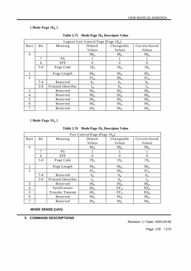
OEM MANUAL:K6602924
5 COMMAND DESCRIPTIONSRevision: 1 / Date: 2003.03.06
Page: 178 / 273
[ Mode Page 18H ]
Table 5.73 Mode Page 18H Descriptor Value
Logical Unit Control Page (Page 18H)Byte Bit Meaning Default
ValuesChangeable
ValuesCurrent/Saved
Values0 98H 98H 98H
7 PS 1 1 16 SPF 0 0 0
5-0 Page Code 18H 18H 18H
1 Page Length 06H 06H 06H
2 01H 00H 01H
7-4 Reserved 0H 0H 0H
3-0 Protocol Identifier 1H 0H 1H
3 Reserved 00H 00H 00H
4 Reserved 00H 00H 00H
5 Reserved 00H 00H 00H
Reserved 00H 00H 00H67 Reserved 00H 00H 00H
[ Mode Page 19H ]
Table 5.74 Mode Page 19H Descriptor Value
Port Control Page (Page 19H)Byte Bit Meaning Default
ValuesChangeable
ValuesCurrent/Saved
Values0 99H 99H 99H
7 PS 1 1 16 SPF 0 0 0
5-0 Page Code 19H 19H 19H
1 Page Length 06H 06H 06H
2 01H 00H 01H
7-4 Reserved 0H 0H 0H
3-0 Protocol Identifier 1H 0H 1H
3 Reserved 00H 00H 00H
4 Synchronous 00H FFH XXH
5 Transfer Timeout 00H FFH XXH
Reserved 00H 00H 00H67 Reserved 00H 00H 00H
MODE SENSE:(1Ah)

OEM MANUAL:K6602924
5 COMMAND DESCRIPTIONSRevision: 1 / Date: 2003.03.06
Page: 179 / 273
[ Mode Page 19H , Sub Page 01H]
Table 5.75 Mode Page 19H , Sub Page 01H Descriptor Value
Margin Control Page (Page 19H, Sub Page 01H)Byte Bit Meaning Default
ValuesChangeable
ValuesCurrent/Saved
ValuesD9H D9H D9H
7 PS 1 1 16 SPF 1 1 1
0
5-0 Page Code 19H 19H 19H
1 Sub Page Code 01H 01H 01H
2 Page Length 00H 00H 00H
3 12H 12H 12H
4 Reserved 00H 00H 00H
01H 00H 01H
7-4 Reserved 0H 0H 0H
5
3-0 Protocol Identifier 1H 0H 1H
6 Reserved 00H 00H 00H
00H F0H X0H
7-4 Driver Strength 0H FH XH
7
3-0 Reserved 0H 0H 0H
01H FFH XXH
7-4 Driver Asymmetry 0H FH XH
8
3-0 DriverPrecompensation
1H FH XH
30H F0H X0H
7-4 Slew Rate 3H FH XH
9
3-0 Reserve 0H 0H 0H
10 Reserved 00H 00H 00H
11 Reserved 00H 00H 00H
12 Reserved 00H 00H 00H
13 Vendor Specific 00H 00H 00H
14 Reserved 00H 00H 00H
15 Reserved 00H 00H 00H
16 Reserved 00H 00H 00H
17 Reserved 00H 00H 00H
18 Reserved 00H 00H 00H
19 Reserved 00H 00H 00H
20 Reserved 00H 00H 00H
21 Reserved 00H 00H 00H
MODE SENSE:(1Ah)

OEM MANUAL:K6602924
5 COMMAND DESCRIPTIONSRevision: 1 / Date: 2003.03.06
Page: 180 / 273
[ Mode Page 19H , Sub Page 02H]
Table 5.76 Mode Page 19H , Sub Page 02H Descriptor Value
Saved Training Configuration Page (Page 19H, Sub Page 02H)Byte Bit Meaning Default
ValuesChangeable
ValuesCurrent/Saved
Values59H 59H 59H
7 PS 0 0 06 SPF 1 1 1
0
5-0 Page Code 19H 19H 19H
1 Sub Page Code 02H 02H 02H
2 Page Length 00H 00H 00H
3 E6H E6H E6H
4 Reserved 00H 00H 00H
01H 00H 01H
7-4 Reserved 0H 0H 0H
5
3-0 Protocol Identifier 1H 0H 1H
6-9 Reserved 00H -00H 00H -00H 00H -00H
10-13 DB (0) Value 00000000H 00000000H XXXXXXXXH
14-17 DB (1) Value 00000000H 00000000H XXXXXXXXH
18-21 DB (2) Value 00000000H 00000000H XXXXXXXXH
22-25 DB (3) Value 00000000H 00000000H XXXXXXXXH
26-29 DB (4) Value 00000000H 00000000H XXXXXXXXH
30-33 DB (5) Value 00000000H 00000000H XXXXXXXXH
34-37 DB (6) Value 00000000H 00000000H XXXXXXXXH
38-41 DB (7) Value 00000000H 00000000H XXXXXXXXH
42-45 DB (8) Value 00000000H 00000000H XXXXXXXXH
46-49 DB (9) Value 00000000H 00000000H XXXXXXXXH
50-53 DB (10) Value 00000000H 00000000H XXXXXXXXH
54-57 DB (11) Value 00000000H 00000000H XXXXXXXXH
58-61 DB (12) Value 00000000H 00000000H XXXXXXXXH
62-65 DB (13) Value 00000000H 00000000H XXXXXXXXH
66-69 DB (14) Value 00000000H 00000000H XXXXXXXXH
70-73 DB (15) Value 00000000H 00000000H XXXXXXXXH
74-77 P_CRCA Value 00000000H 00000000H XXXXXXXXH
78-81 P1 Value 00000000H 00000000H XXXXXXXXH
82-85 BSY Value 00000000H 00000000H 00000000H
86-89 SEL Value 00000000H 00000000H 00000000H
90-93 RST Value 00000000H 00000000H 00000000H
(cont’d)
MODE SENSE:(1Ah)

OEM MANUAL:K6602924
5 COMMAND DESCRIPTIONSRevision: 1 / Date: 2003.03.06
Page: 181 / 273
Table 5.76 Mode Page 19H , Sub Page 02H Descriptor Value (cont’d)
94-97 REQ Value 00000000H 00000000H XXXXXXXXH
98-101 ACK Value 00000000H 00000000H XXXXXXXXH
102-105 ATN Value 00000000H 00000000H 00000000H
106-109 C/D Value 00000000H 00000000H 00000000H
110-113 I/O Value 00000000H 00000000H 00000000H
114-117 MSG Value 00000000H 00000000H 00000000H
118-233 Reserved 00000000H 00000000H 00000000H
[ Mode Page 19H , Sub Page 03H]
Table 5.77 Mode Page 19H , Sub Page 03H Descriptor Value
Negotiated Setting Page (Page 19H, Sub Page 03H)Byte Bit Meaning Default
ValuesChangeable
ValuesCurrent/Saved
Values59H 59H 59H
7 PS 0 0 06 SPF 1 1 1
0
5-0 Page Code 19H 19H 19H
1 Sub Page Code 03H 03H 03H
2 Page Length 00H 00H 00H
3 0AH 0AH 0AH
4 Reserved 00H 00H 00H
01H 00H 01H
7-4 Reserved 0H 0H 0H
5
3-0 Protocol Identifier 1H 0H 1H
6 Transfer PeriodFactor
00H 00H XXH
7 Reserved 00H 00H 00H
8 REQ/ACK Offset 00H 00H XXH
9 Transfer WidthExponent
00H 00H XXH
10 00H 00H XXH
7 Reserved 0 0 06-0 Protocol Option bits 00H 00H XXH
(cont’d)
MODE SENSE:(1Ah)

OEM MANUAL:K6602924
5 COMMAND DESCRIPTIONSRevision: 1 / Date: 2003.03.06
Page: 182 / 273
Table 5.77 Mode Page 19H , Sub Page 03H Descriptor Value (cont’d)
11 00H 00H 0XH
7-4 Reserved 0H 0H 0H
3-2 Transceiver Mode 0H 0H XH
1 Sent PCOMP_EN 0 0 0/10 Received
PCOMP_EN0 0 0/1
12 Reserved 00H 00H 00H
13 Reserved 00H 00H 00H
[ Mode Page 19H , Sub Page 04H]
Mode Page 19H , Sub Page 04H Descriptor Value
Report Transfer Capabilities Page (Page 19H, Sub Page 04H)Byte Bit Meaning Default
ValuesChangeable
ValuesCurrent/Saved
Values59H 59H 59H
7 PS 0 0 06 SPF 1 1 1
0
5-0 Page Code 19H 19H 19H
1 Sub Page Code 04H 04H 04H
2 Page Length 00H 00H 00H
3 0AH 0AH 0AH
4 Reserved 00H 00H 00H
5 01H 01H 01H
7-4 Reserved 0H 0H 0H
3-0 Protocol Identifier 1H 1H 1H
6 Minimum TransferPeriod Factor
00H 00H XXH
7 Reserved 0H 0H 0H
8 MaximumREQ/ACK Offset
00H 00H XXH
9 Maximum TransferWidth Exponent
00H 00H 01H
10 Protocol OptionBits Supported
00H 00H XXH
11 Reserved 00H 00H 00H
12 Reserved 00H 00H 00H
13 Reserved 00H 00H 00H
MODE SENSE:(1Ah)

OEM MANUAL:K6602924
5 COMMAND DESCRIPTIONSRevision: 1 / Date: 2003.03.06
Page: 183 / 273
Single Ended Low Voltage Differential
Current Saved Current Saved1 Minimum Transfer Period Factor 0CH 00H 08H 00H
2 Maximum REQ/ACK Offset 51H 00H 51H 00H
3 Maximum Transfer Width Exponent 01H 00H 01H 00H
4 Protocol Options Bits Supported 00H 00H FFH 00H
[ Mode Page 1AH ]
Table 5.78 Mode Page 1AH Descriptor Value
Power Condition Control Page (Page 1AH)Byte Bit Meaning Default
ValuesChangeable
ValuesCurrent/Saved
Values1AH 1AH 1AH
7 PS 0 0 06 SPF 0 0 0
0
5-0 Page Code 1AH 1AH 1AH
1 Page Length 0AH 0AH 0AH
2 Reserved 00H 00H 00H
02H 00H 02H
7-2 Reserved 0H 0H 0H
3
1 Idle 1 0 10 Standby 0 0 0
4 00H 00H 00H
5 Idle Condition 00H 00H 00H
6 Timer 00H 00H 00H
7 01H 00H 01H
8 00H 00H 00H
9 Standby Condition 00H 00H 00H
10 Timer 00H 00H 00H
11 00H 00H 00H
MODE SENSE:(1Ah)

OEM MANUAL:K6602924
5 COMMAND DESCRIPTIONSRevision: 1 / Date: 2003.03.06
Page: 184 / 273
[ Mode Page 1CH ]
Table 5.79 Mode Page 1CH Descriptor Value
Informational Exceptions Control Page (Page 1CH)Byte Bit Meaning Default
ValuesChangeable
ValuesCurrent/Saved
Values0 9CH 9CH 9CH
7 PS 1 1 16 SPF 0 0 0
5-0 Page Code 1CH 1CH 1CH
1 Page Length 0AH 0AH 0AH
2 29H BDH XXH
7 Perf 0 1 0/16 Reserved 0 0 05 EBF 1 1 0/14 EWasc 0 1 0/13 DExcpt 1 1 0/12 Test 0 1 0/11 Reserved 0 0 00 LogErr 1 1 0/1
3 04H 0FH 0XH
7-4 Reserved 0H 0H 0H
3-0 MRIE 4H FH XH
4 00H FFH XXH
5 Interval 00H FFH XXH
6 Timer 00H FFH XXH
7 00H FFH XXH
8 00H FFH XXH
9 Report 00H FFH XXH
10 Count 00H FFH XXH
11 01H FFH XXH
MODE SENSE:(1Ah)

OEM MANUAL:K6602924
5 COMMAND DESCRIPTIONSRevision: 1 / Date: 2003.03.06
Page: 185 / 273
5.8 MODE SENSE (10):(5AH)
BitByte
7 6 5 4 3 2 1 0
0 Operation Code (5AH)0 1 0 1 1 0 1 0
1 Logical Unit Number R DBD Reserved0 0 0 0
2 PC Page Code
3 Sub Page Code
4 Reserved0 0 0 0 0 0 0 0
5 Reserved0 0 0 0 0 0 0 0
6 Reserved0 0 0 0 0 0 0 0
7 Allocation Length (MSB)
8 Allocation Length (LSB)
9 Vendor Unique Reserved Flag Link0 0 0 0 0 0
The MODE SENSE (10) command is the same as the MODE SENSE commandexcept that the MODE SENSE (10) command has 2-byte length of Allocation Lengthand 8-byte length of MODE SENSE Header as follows.
Refer to item 5.7 MODE SENSE command in detail.
MODE SENSE (10):(5Ah)

OEM MANUAL:K6602924
5 COMMAND DESCRIPTIONSRevision: 1 / Date: 2003.03.06
Page: 186 / 273
Table 5.80 MODE SENSE (10) Header
BitByte
7 6 5 4 3 2 1 0
0 Sense Data Length (MSB)
1 Sense Data Length (LSB)
2 Medium Type0 0 0 0 0 0 0 0
3 WP Reserved DPOFUA Reserved0 0 0 0 0 0
4 Reserved0 0 0 0 0 0 0 0
5 Reserved0 0 0 0 0 0 0 0
6 Block Descriptor Length (MSB)0 0 0 0 0 0 0 0
7 Block Descriptor Length (LSB)0 0 0 0 1 0 0 0
MODE SENSE (10):(5Ah)

OEM MANUAL:K6602924
5 COMMAND DESCRIPTIONSRevision: 1 / Date: 2003.03.06
Page: 187 / 273
5.9 PERSISTENT RESERVE IN:(5Eh)
BitByte
7 6 5 4 3 2 1 0
0 Operation Code(5EH)0 1 0 1 1 1 1 0
1 Logical Unit Number Service Action
2 Reserved0 0 0 0 0 0 0 0
3 Reserved0 0 0 0 0 0 0 0
4 Reserved0 0 0 0 0 0 0 0
5 Reserved0 0 0 0 0 0 0 0
6 Reserved0 0 0 0 0 0 0 0
7 Allocation Length (MSB)
8 Allocation Length (LSB)
9 Vendor Unique Reserved Flag Link0 0 0 0 0 0
The PERSISTENT RESERVE IN command is used to obtain information aboutpersistent reservations and reservation keys that are active within the controller.This command is used in conjunction with the PERSISTENT RESERVE OUTcommand (see 5.10).
The PERSISTENT RESERVE IN parameter data includes a field that indicates thenumber of parameter data bytes available to be returned. The Allocation Length fieldin the CDB indicates how much space has been allocated for the returned parameterlist. An allocation length that is not sufficient to contain the entire parameter listshall not be considered an error. If the complete list is required, the application clientshould send a new PERSISTENT RESERVE IN command with allocation lengthlarge enough to contain the entire list.
The service action codes for the PERSISTENT RESERVE IN command are defined inTable 5.81.
PERSISTENT RESERVE IN:(5Eh)

OEM MANUAL:K6602924
5 COMMAND DESCRIPTIONSRevision: 1 / Date: 2003.03.06
Page: 188 / 273
Table 5.81 PERSISTENT RESERVE IN Service Action Code
Code Name Description00H READ KEYS Reads all registered Reservation Keys01H READ RESERVATION Reads the current persistent reservations
02H-1FH Reserved Reserved
When Service Action Code reserved by Service Action is specified, a controller setsINVALID FIELD IN CDB to a sense key at ILLEGAL REQUEST and a additionalsense key, and makes it CHECK CONDITION status.
The format for the parameter data provided in response to a PERSISTENTRESERVE IN command with the READ KEYS service action is shown in Table 5.82..
Table 5.82 READ KEYS Parameter Data
BitByte
7 6 5 4 3 2 1 0
0 (MSB)• GENERATION•3 (LSB)4 (MSB)• Additional Length(N-7)•7 (LSB)
Reservation Key List
8 (MSB)• First reservation key•15 (LSB)• •• •
N-7 (MSB)• Last reservation key•N (LSB)
PERSISTENT RESERVE IN:(5Eh)

OEM MANUAL:K6602924
5 COMMAND DESCRIPTIONSRevision: 1 / Date: 2003.03.06
Page: 189 / 273
The GENERATION field shall contain a 32-bit counter maintained by the deviceserver that shall be incremented every time a PERSISTENT RESERVE OUTcommand requests a REGISTER, a REGISTER AND IGNORE EXISTING KEY, aCLEAR, a PREEMPT, or a PREEMPT AND ABORT service action. The counter shallnot be incremented by a PERSISTENT RESERVE IN command, by a PERSISTENTRESERVE OUT command that performs a RESERVE or RELEASE service action, orby a PERSISTENT RESERVE OUT command that is terminated due to an error orreservation conflict. Regardless of the APTPL bit value the generation value shall beset to zero as part of the power on reset process.
The additional length field contains a count of the number of bytes in the Reservationkey list. If the allocation length specified by the PERSISTENT RESERVE INcommand is not sufficient to contain the entire parameter list, then only the firstportion of the list (byte 0 to the allocation length) shall be sent to the applicationclient. The incremental remaining bytes shall be truncated, although the additionallength field shall still contain the actual number of bytes in the reservation key listwithout consideration of any truncation resulting from an insufficient allocationlength. This shall not be considered an error.
The reservation key list contains the 8-byte reservation keys for all initiators thathave registered through all ports with the device server.
The format for the parameter data provided in response to a PERSISTENTRESERVE IN command with the READ RESERVATION service action is shown inTable 5.83.
Table 5.83 READ RESERVATION Parameter Data
BitByte
7 6 5 4 3 2 1 0
0 (MSB)• GENERATION•3 (LSB)4 (MSB)• Additional Length(N-7)•7 (LSB)
(cont’d)
PERSISTENT RESERVE IN:(5Eh)

OEM MANUAL:K6602924
5 COMMAND DESCRIPTIONSRevision: 1 / Date: 2003.03.06
Page: 190 / 273
Table 5.83 READ RESERVATION Parameter Data (cont’d)
Reservation Descriptors
8 (MSB)• Reservation Descriptor•N (LSB)
The GENERATION field shall contain a 32-bit counter maintained by the deviceserver that shall be incremented every time a PERSISTENT RESERVE OUTcommand requests a REGISTER, a REGISTER AND IGNORE EXISTING KEY, aCLEAR, a PREEMPT, or a PREEMPT AND ABORT service action. The counter shallnot be incremented by a PERSISTENT RESERVE IN command, by a PERSISTENTRESERVE OUT command that performs a RESERVE or RELEASE service action, orby a PERSISTENT RESERVE OUT command that is terminated due to an error orreservation conflict. Regardless of the APTPL bit value the generation value shall beset to zero as part of the power on reset process.
The additional length field contains a count of the number of bytes to follow inreservation descriptor(s). If the allocation length specified by the PERSISTENTRESERVE IN command is not sufficient to contain the entire parameter list, thenonly the first portion of the list (byte 0 to the allocation length) shall be sent to theapplication client. The incremental remaining bytes shall be truncated, although theadditional length field shall still contain the actual number of bytes of reservationdescriptor(s) and shall not be affected by the truncation. This shall not be consideredan error.
The format of the reservation descriptors is defined in Table 5.84. There shall be areservation descriptor for the persistent reservation, if any, present in the logical unitand a reservation descriptor for each element, if any, having a persistent reservation.
Table 5.84 PERSISTENT RESERVE IN reservation descriptor
BitByte
7 6 5 4 3 2 1 0
0 (MSB)• Reservation Key•7 (LSB)
(cont’d)
PERSISTENT RESERVE IN:(5Eh)

OEM MANUAL:K6602924
5 COMMAND DESCRIPTIONSRevision: 1 / Date: 2003.03.06
Page: 191 / 273
Table 5.84 PERSISTENT RESERVE IN reservation descriptor (cont’d)
8 (MSB)• Scope-Specific Address•11 (LSB)12 Reserved
13 Scope Type
14 Reserved
15 Reserved
If a persistent reservation is present in the logical unit that does not containelements, there shall be a single reservation descriptor in the list of parameter datareturned by the device server in response to the PERSISTENT RESERVE INcommand with a READ RESERVATION service action. The reservation descriptorfor each reservation shall contain the reservation key under which the persistentreservation is held.
The type and scope of each persistent reservation as present in the PERSISTENTRESERVE OUT command that created the persistent reservation shall be returned.
If a persistent reservation is present in the logical unit that does contain elements,there shall be a reservation descriptor in the list of parameter data returned by thedevice server in response to the PERSISTENT RESERVE IN command with a READRESERVATION service action for the LU_SCOPE persistent reservation that is held,if any, and each ELEMENT_SCOPE persistent reservation that may be held. Thereservation descriptor shall contain the RESERVATION KEY under which thepersistent reservation is held. The TYPE and SCOPE of the persistent reservation aspresent in the PERSISTENT RESERVE OUT command that created the persistentreservation shall be returned.
If the scope is an ELEMENT_SCOPE reservation, the scope-specific address fieldshall contain the element address, zero filled in the most significant bits to fit thefield. If the scope is a LU_SCOPE reservation, the scope-specific address field shallbe set to zero.
Since the controller does not support ELEMENT_SCOPE reservation.
PERSISTENT RESERVE IN:(5Eh)
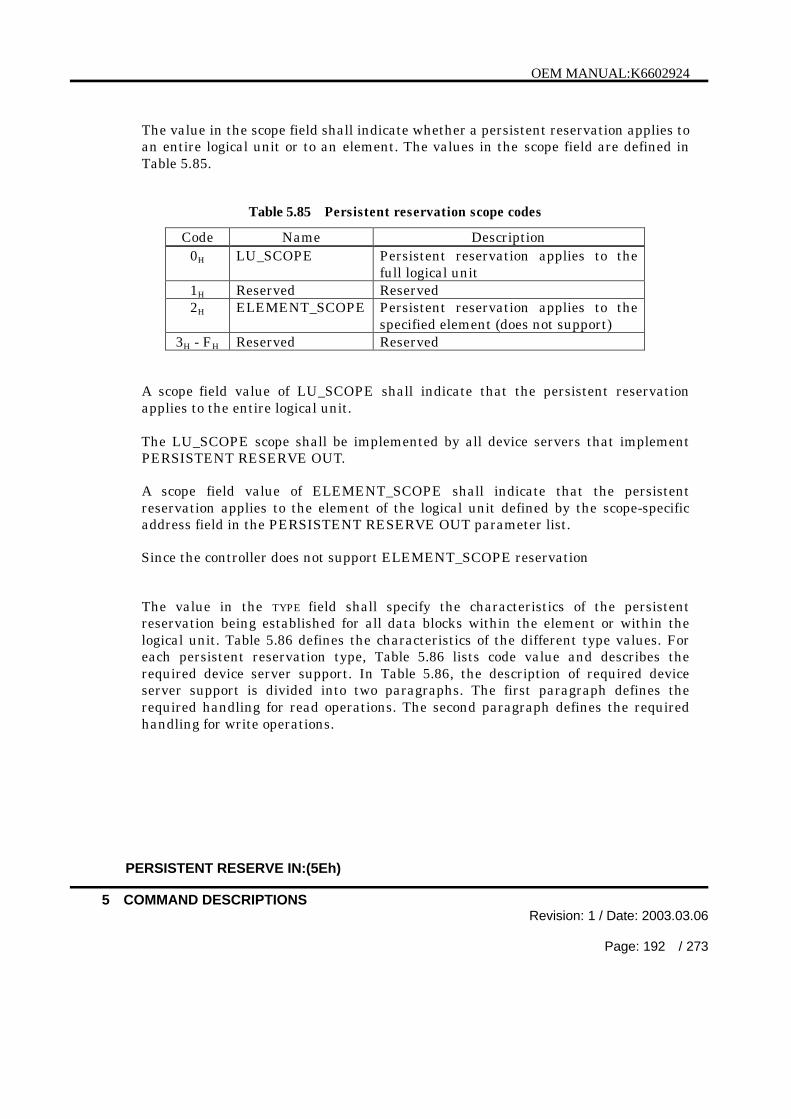
OEM MANUAL:K6602924
5 COMMAND DESCRIPTIONSRevision: 1 / Date: 2003.03.06
Page: 192 / 273
The value in the scope field shall indicate whether a persistent reservation applies toan entire logical unit or to an element. The values in the scope field are defined inTable 5.85.
Table 5.85 Persistent reservation scope codes
Code Name Description0H LU_SCOPE Persistent reservation applies to the
full logical unit1H Reserved Reserved2H ELEMENT_SCOPE Persistent reservation applies to the
specified element (does not support)3H - FH Reserved Reserved
A scope field value of LU_SCOPE shall indicate that the persistent reservationapplies to the entire logical unit.
The LU_SCOPE scope shall be implemented by all device servers that implementPERSISTENT RESERVE OUT.
A scope field value of ELEMENT_SCOPE shall indicate that the persistentreservation applies to the element of the logical unit defined by the scope-specificaddress field in the PERSISTENT RESERVE OUT parameter list.
Since the controller does not support ELEMENT_SCOPE reservation
The value in the TYPE field shall specify the characteristics of the persistentreservation being established for all data blocks within the element or within thelogical unit. Table 5.86 defines the characteristics of the different type values. Foreach persistent reservation type, Table 5.86 lists code value and describes therequired device server support. In Table 5.86, the description of required deviceserver support is divided into two paragraphs. The first paragraph defines therequired handling for read operations. The second paragraph defines the requiredhandling for write operations.
PERSISTENT RESERVE IN:(5Eh)

OEM MANUAL:K6602924
5 COMMAND DESCRIPTIONSRevision: 1 / Date: 2003.03.06
Page: 193 / 273
Table 5.86 Persistent Reservation Type Code
Code Name Description0H Reserved Reserved1H WRITE
EXCLUSIVEReads Shared: Any application client on any initiator mayinitiate tasks that request transfers from the storagemedium or cache of the logical unit to the initiator.Writes Exclusive: Any task from any initiator other thanthe initiator holding the persistent reservation thatrequests a transfer from the initiator to the storagemedium or cache of the logical unit shall be terminatedwith RESERVATION CONFLICT status.
2H Reserved Reserved3H EXCLUSIVE
ACCESSReads Exclusive: Any task from any initiator other thanthe initiator holding the persistent reservation thatrequests a transfer from the storage medium or cache ofthe logical unit to the initiator shall be terminated withRESERVATION CONFLICT status.Writes Exclusive: Any task from any initiator other thanthe initiator holding the persistent reservation thatrequests a transfer from the initiator to the storagemedium or cache of the logical unit shall be terminatedwith RESERVATION CONFLICT status.
4H Reserved Reserved5H WRITE
EXCLUSIVE-REGISTRANTSONLY
Reads Shared: Any application client on any initiator mayinitiate tasks that request transfers from the storagemedium or cache of the logical unit to the initiator.Writes Exclusive: A task that requests a transfer to thestorage medium or cache of the logical unit from aninitiator that is not currently registered with the deviceserver shall be terminated with RESERVATIONCONFLICT status.
6H EXCLUSIVEACCESS-REGISTRANTSONLY
Reads Exclusive: A task that requests a transfer from thestorage medium or cache of the logical unit to an initiatorthat is not currently registered with the device server shallbe terminated with RESERVATION CONFLICT status.Writes Exclusive: A task that requests a transfer to thestorage medium or cache of the logical unit from aninitiator that is not currently registered with the deviceserver shall be terminated with RESERVATIONCONFLICT status.
7H - FH Reserved Reserved
PERSISTENT RESERVE IN:(5Eh)
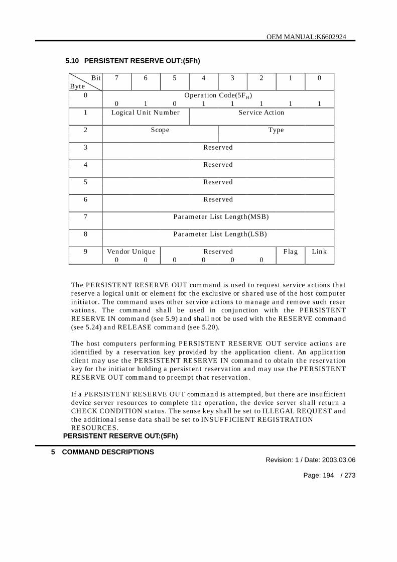
OEM MANUAL:K6602924
5 COMMAND DESCRIPTIONSRevision: 1 / Date: 2003.03.06
Page: 194 / 273
5.10 PERSISTENT RESERVE OUT:(5Fh)
BitByte
7 6 5 4 3 2 1 0
0 Operation Code(5FH)0 1 0 1 1 1 1 1
1 Logical Unit Number Service Action
2 Scope Type
3 Reserved
4 Reserved
5 Reserved
6 Reserved
7 Parameter List Length(MSB)
8 Parameter List Length(LSB)
9 Vendor Unique Reserved Flag Link0 0 0 0 0 0
The PERSISTENT RESERVE OUT command is used to request service actions thatreserve a logical unit or element for the exclusive or shared use of the host computerinitiator. The command uses other service actions to manage and remove such reservations. The command shall be used in conjunction with the PERSISTENTRESERVE IN command (see 5.9) and shall not be used with the RESERVE command(see 5.24) and RELEASE command (see 5.20).
The host computers performing PERSISTENT RESERVE OUT service actions areidentified by a reservation key provided by the application client. An applicationclient may use the PERSISTENT RESERVE IN command to obtain the reservationkey for the initiator holding a persistent reservation and may use the PERSISTENTRESERVE OUT command to preempt that reservation.
If a PERSISTENT RESERVE OUT command is attempted, but there are insufficientdevice server resources to complete the operation, the device server shall return aCHECK CONDITION status. The sense key shall be set to ILLEGAL REQUEST andthe additional sense data shall be set to INSUFFICIENT REGISTRATIONRESOURCES.
PERSISTENT RESERVE OUT:(5Fh)

OEM MANUAL:K6602924
5 COMMAND DESCRIPTIONSRevision: 1 / Date: 2003.03.06
Page: 195 / 273
This controller can register one Reservation Key per host. That is, Reservation Keyof a maximum of 16 can be registered by the whole the controller.
The PERSISTENT RESERVE OUT command contains fields that specify apersistent reservation service action, the intended scope of the persistent reservation,and the restrictions caused by the persistent reservation. The type and scope fieldsare defined in Table 5.86 and Table 5.85. If a scope field specifies a scope that is notimplemented, the device server shall return a CHECK CONDITION status. Thesense key shall be set to ILLEGAL REQUEST and additional sense data shall be setto INVALID FIELD IN CDB.
Fields contained in the PERSISTENT RESERVE OUT parameter list specify theinformation required to perform a particular persistent reservation service action.
The parameter list shall be 24 bytes in length and the PARAMETER LIST LENGTHfield shall contain 24 (18h). If the parameter list length is not 24, the controller shallreturn a CHECK CONDITION status. The sense key shall be set to ILLEGALREQUEST and the additional sense data shall be set to PARAMETER LISTLENGTH ERROR.
When processing the PERSISTENT RESERVE OUT service actions, the deviceserver shall increment the generation value as specified in section 5.9.
The PERSISTENT RESERVE OUT command service actions are defined in Table5.87.
Table 5.87 PERSISTENT RESERVE OUT Service Action Code
Code Name Description GENERATIONfieldincremented
00H REGISTER Register a reservation key with the deviceserver.
Yes
01H RESERVE Creates a persistent reservation having aspecified scope and type. The scope and typeof a persistent reservation.
No
02H RELEASE Releases the selected reservation for therequesting initiator.
No
03H CLEAR Clears all reservation keys and all persistentreservations.
Yes
04H PREEMPT Preempts persistent reservations fromanother host computer.
Yes
(cont’d)
PERSISTENT RESERVE OUT:(5Fh)

OEM MANUAL:K6602924
5 COMMAND DESCRIPTIONSRevision: 1 / Date: 2003.03.06
Page: 196 / 273
Table 5.87 PERSISTENT RESERVE OUT Service Action Code (cont’d)
05H PREEMPTANDABORT
Preempts persistent reservations fromanother initiator and aborts all tasks for allinitiators registered with the specifiedreservation key.
Yes
06H REGISTERANDIGNOREEXISTINGKEY
Register a reservation key with the controller. Yes
07H –1FH
Reserved Reserved -
The parameter list required to perform the PERSISTENT RESERVE OUT commandis defined in Table 5.88. All fields shall be sent on all PERSISTENT RESERVE OUTcommands, even if the field is not required for the specified service action and scopevalues.
Table 5.88 PERSISTENT RESERVATION OUT Parameter List
BitByte
7 6 5 4 3 2 1 0
0 (MSB)• Reservation Key•7 (LSB)8 (MSB)• Service Action Reservation Key•15 (LSB)16 (MSB)• Scope-Specific Address•19 (LSB)20 Reserved APTPL
21 Reserved
22 Reserved
23 Reserved
PERSISTENT RESERVE OUT:(5Fh)
OEM MANUAL:K6602924
5 COMMAND DESCRIPTIONSRevision: 1 / Date: 2003.03.06
Page: 197 / 273
The reservation key field contains an 8-byte value provided by the host computer tothe controller to identify the initiator that is the source of the PERSISTENTRESERVE OUT command. The device server shall verify that the contents of thereservation key field in a PERSISTENT RESERVE OUT command parameter datamatches the registered reservation key for the initiator from which the task wasreceived, except for:
a) the REGISTER AND IGNORE EXISTING KEY service action where theRESERVATION KEY field shall be ignored; and
b) the REGISTER service action for an unregistered initiator where theRESERVATION KEY field shall contain zero.
Except as noted above, when a PERSISTENT RESERVE OUT command specifies areservation key field other than the reservation key registered for the initiator thedevice server shall return a RESERVATION CONFLICT status. Except as notedabove, the reservation key of the initiator shall be verified to be correct regardless ofthe service action and scope field values.
The service action reservation key field contains information needed for four serviceactions; the REGISTER, REGISTER AND IGNORE EXISTING KEY, PREEMPT,and PREEMPT AND ABORT service actions. For the REGISTER and REGISTERAND IGNORE EXISTING KEY service action, the service action reservation keyfield contains the new reservation key to be registered. For the PREEMPT andPREEMPT AND ABORT service actions, the service action reservation key fieldcontains the reservation key of the persistent reservations that are being preempted.The service action reservation key field is ignored for all other service actions.
If the scope is an ELEMENT_SCOPE reservation, the scope-specific address fieldshall contain the element address, zero filled in the most significant bits to fit thefield. If the service action is REGISTER, REGISTER AND IGNORE EXISTING KEY,or CLEAR or if the scope is a LU_SCOPE reservation, the scope-specific address fieldshall be set to zero.Since the controller supports only LU_SCOPE, when value other than zero isspecified to be scope-specific addresses, it ignored value.
The APTPL (Activate Persist Through Power Loss) bit shall be valid only for theREGISTER, or the REGISTER AND IGNORE EXISTING KEY service action. In allother cases, the APTPL bit shall be ignored. Support for an APTPL bit equal to one isoptional. If a device server that does not support the APTPL bit value of one receivesthat value in a REGISTER or a REGISTER AND IGNORE EXISTING KEY serviceaction, the device server shall return a CHECK CONDITION status. The sense keyshall be set to ILLEGAL REQUEST and additional sense code shall be set toINVALID FIELD IN PARAMETER LIST.
PERSISTENT RESERVE OUT:(5Fh)

OEM MANUAL:K6602924
5 COMMAND DESCRIPTIONSRevision: 1 / Date: 2003.03.06
Page: 198 / 273
If the last valid APTPL bit value received by the controller is zero, the loss of powerin the target shall release the persistent reservation for all logical units and removeall reservation keys. If the last valid APTPL bit value received by the controller is one,the logical unit shall retain any persistent reservation(s) that may be present and allreservation keys for all initiators even if power is lost and later returned.
Table 5.89 summarizes which fields are set by the application client and interpretedby the device server for each service action and scope value. The APTPL bit in thePERSISTENT RESERVE OUT parameter list, specified in the previous paragraph,is not summarized in Table 5.89.
Table 5.89 PERSISTENT RESERVE OUT Service Actions and Valid Parameters
Parameters
ServiceAction
Allowed scopetype Reservation
key
Serviceaction
reservationkey
Scope-specificaddress
REGISTER Ignored Ignored Valid Valid IgnoredREGISTERANDIGNOREEXISTINGKEY
Ignored Ignored Ignored Valid Ignored
RESERVE LU_SCOPE IgnoredELEMENT_SCOPE
Valid Valid IgnoredValid(element)
RELEASE LU_SCOPE IgnoredELEMENT_SCOPE
Valid Valid IgnoredValid(element)
CLEAR Ignored Ignored Valid Ignored IgnoredLU_SCOPE IgnoredPREEMPTELEMENT_SCOPE
Valid Valid ValidValid(element)
LU_SCOPE IgnoredPREEMPTAND ABORT ELEMENT_SCOPE
Valid valid ValidValid(element)
PERSISTENT RESERVE OUT:(5Fh)

OEM MANUAL:K6602924
5 COMMAND DESCRIPTIONSRevision: 1 / Date: 2003.03.06
Page: 199 / 273
5.11 READ:(08H)
BitByte
7 6 5 4 3 2 1 0
0 Operation Code (08H)0 0 0 0 1 0 0 0
1 Logical Unit Number Logical Block Address (MSB)
2 Logical Block Address
3 Logical Block Address (LSB)
4 Transfer Length
5 Vendor Unique Reserved Flag Link0 0 0 0 0 0
The READ command transfers to the host computer the number of consecutive datablocks from the medium specified in the transfer length field starting at the blockaddress specified in the logical block address field. This command is used totransfer the latest data written in the specified blocks.
When a 0 is specified in the transfer length field, 256 blocks of data are transferred.
The controller terminates the command with a CHECK CONDITION status andwith the “ILLEGAL REQUEST” sense key an invalid logical block address isspecified (see Note). For other errors, the controller terminates the commandwith the CHECK CONDITION status and the appropriate sense key.
Note : The information byte field of the sense data is loaded with the last logicalblock address.
READ:(08h)

OEM MANUAL:K6602924
5 COMMAND DESCRIPTIONSRevision: 1 / Date: 2003.03.06
Page: 200 / 273
5.12 READ (EXTENDED):(28H)
BitByte
7 6 5 4 3 2 1 0
0 Operation Code (28H)0 0 1 0 1 0 0 0
1 Logical Unit Number DPO FUA Reserved RelAdr0 0 0
2 Logical Block Address (MSB)
3 Logical Block Address
4 Logical Block Address
5 Logical Block Address (LSB)
6 Reserved0 0 0 0 0 0 0 0
7 Transfer Length (MSB)
8 Transfer Length (LSB)
9 Vendor Unique Reserved Flag Link0 0 0 0 0 0
The READ command requests the controller to transfer the number of consecutiveblocks specified in the Transfer Length field to the host computer starting at theblock address specified in the Logical Block Address field. This command causes thecontroller to transfer the latest data written on the specified blocks.
The DPO (Disable Page Out) bit is used to determine the priority of the logical blockdata read by this command in the cache.
But in this controller, the priority of the retained data is controlled by the value of theRetention Priority field in the mode page 8 (Caching Page; refer to Table 5.36) or thealgorithm implementing the cache replacement strategy irrespective of DPO bit.
If the FUA (Force Unit Access) bit is set to 0, the controller may satisfy the commandby accessing the cache.
READ (EXTENDED):(28h)
OEM MANUAL:K6602924
5 COMMAND DESCRIPTIONSRevision: 1 / Date: 2003.03.06
Page: 201 / 273
A Transfer Length of 0 specifies that no logical block is to be transferred. Thecontroller in this case only seeks to the track containing the block specified in theLogical Block Address.
The controller terminates the command with a Check Condition status and withthe “Illegal Request” Sense Key if an invalid logical block address is specified (seeNote). For other errors, the controller terminates the command with the CHECKCONDITION status and the appropriate sense key.
Note : The information byte field of the sense data is loaded with the last logicalblock address.
READ (EXTENDED):(28h)

OEM MANUAL:K6602924
5 COMMAND DESCRIPTIONSRevision: 1 / Date: 2003.03.06
Page: 202 / 273
5.13 READ BUFFER:(3CH)
BitByte
7 6 5 4 3 2 1 0
0 Operation Code (3CH)0 0 1 1 1 1 0 0
1 Logical Unit Number Reserved Mode0
2 Buffer ID0 0 0 0 0 0 0 0
3 Buffer Offset (MSB)
4 Buffer Offset
5 Buffer Offset (LSB)
6 Allocation Length (MSB)
7 Allocation Length
8 Allocation Length (LSB)
9 Vendor Unique Reserved Flag Link0 0 0 0 0 0
The READ BUFFER command transfers the data from the controller’s data buffermemory to the host computer.
This command can be used in conjunction with the WRITE BUFFER command (see5.37) as a diagnostic function for testing the controller's data buffer memory and theSCSI bus. This command does not cause the controller to access the logical unitmedium.
The function of this command is determined by the Mode field as follows.
Table 5.90 Read Buffer Mode
Mode MeaningBit 3 Bit 2 Bit 1 Bit 0
0 0 0 0 Combined Header and Data0 0 0 1 Combined Header and Data (Buffer Offset)0 0 1 0 Data0 0 1 1 Descriptor
(cont’d)
READ BUFFER:(3Ch)

OEM MANUAL:K6602924
5 COMMAND DESCRIPTIONSRevision: 1 / Date: 2003.03.06
Page: 203 / 273
Table 5.90 Read Buffer Mode (cont’d)
0 1 0 0 Reserved0 1 0 1 Reserved0 1 1 0 Reserved0 1 1 1 Reserved1 0 0 0 Reserved1 0 0 1 Reserved1 0 1 0 Echo Buffer1 0 1 1 Echo Buffer Descriptor1 1 0 0 Reserved
| |1 1 1 1 Reserved
The controller does not use the Buffer ID field (ignored).
The Buffer Offset specifies the leading buffer address to begin the data transfer.
The Allocation Length specifies the maximum number of bytes which the hostcomputer allocated to the data to be transferred during the DATA IN phase. Thecontroller will not transfer more data than that specified in the Allocation Length.When an Allocation Length is specified to 0, no data is transferred. The controllerdoes not consider this condition as an error.
The controller terminates the DATA IN phase when it has transferred the data of theAllocation Length or all the data available, whichever is less.
The Buffer Offset and Allocation Length fields must be set aligned on four-byteboundaries. If these fields do not be set aligned on four-byte, READ BUFFERcommand will be terminated with a CHECK CONDITION status, a sense key ofILLEGAL REQUEST.
(1) Combined Header and DataIn this mode, the 4-byte header (see Table 5.91) is transferred first and the datais subsequently transferred starting from the leading edge of the buffer.The Buffer Offset must be specified to 0.
(2) Combined header and Data (Buffer Offset)In this mode, the 4-byte header (see Table 5.91) is transferred first and the datais subsequently transferred starting from the address as specified in the BufferOffset field.
READ BUFFER:(3Ch)
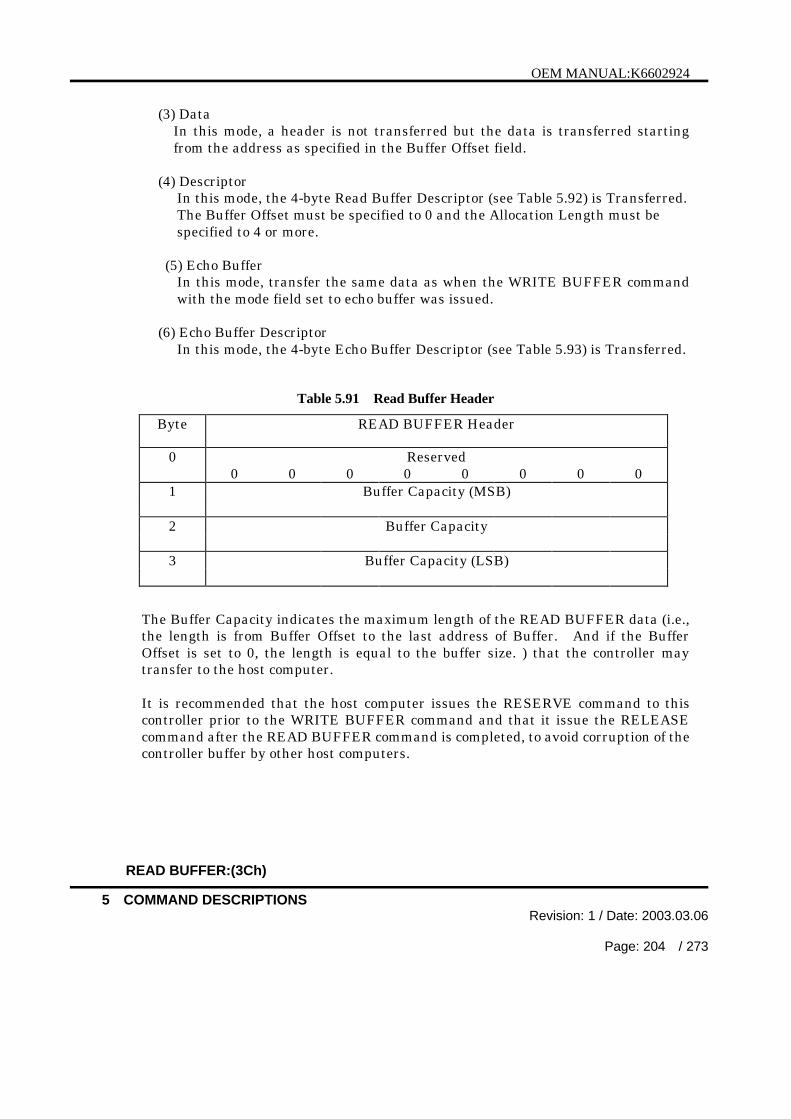
OEM MANUAL:K6602924
5 COMMAND DESCRIPTIONSRevision: 1 / Date: 2003.03.06
Page: 204 / 273
(3) DataIn this mode, a header is not transferred but the data is transferred startingfrom the address as specified in the Buffer Offset field.
(4) DescriptorIn this mode, the 4-byte Read Buffer Descriptor (see Table 5.92) is Transferred.The Buffer Offset must be specified to 0 and the Allocation Length must bespecified to 4 or more.
(5) Echo BufferIn this mode, transfer the same data as when the WRITE BUFFER commandwith the mode field set to echo buffer was issued.
(6) Echo Buffer DescriptorIn this mode, the 4-byte Echo Buffer Descriptor (see Table 5.93) is Transferred.
Table 5.91 Read Buffer Header
Byte READ BUFFER Header
0 Reserved0 0 0 0 0 0 0 0
1 Buffer Capacity (MSB)
2 Buffer Capacity
3 Buffer Capacity (LSB)
The Buffer Capacity indicates the maximum length of the READ BUFFER data (i.e.,the length is from Buffer Offset to the last address of Buffer. And if the BufferOffset is set to 0, the length is equal to the buffer size. ) that the controller maytransfer to the host computer.
It is recommended that the host computer issues the RESERVE command to thiscontroller prior to the WRITE BUFFER command and that it issue the RELEASEcommand after the READ BUFFER command is completed, to avoid corruption of thecontroller buffer by other host computers.
READ BUFFER:(3Ch)

OEM MANUAL:K6602924
5 COMMAND DESCRIPTIONSRevision: 1 / Date: 2003.03.06
Page: 205 / 273
Table 5.92 Read Buffer Descriptor
Byte Read Buffer Descriptor
0 Offset Boundary0 0 0 0 0 0 1 0
1 Buffer Capacity (MSB)
2 Buffer Capacity
3 Buffer Capacity (LSB)
The Offset Boundary is set to 02H and indicates that the four-byte boundariesassignment is possible as a Buffer Offset.
The Buffer Capacity indicates the maximum buffer size.
Table 5.93 Echo Buffer Descriptor
Byte Echo Buffer Descriptor
0 Reserved EBOS0 0 0 0 0 0 0 1
1 Reserved0 0 0 0 0 0 0 0
2 Reserved0 0 0 0 0 0 0 0
3 Buffer Capacity
The EBOS (Echo Buffer Overwritten Supported) bit displays whether the datatransmitted in the Echo Buffer Mode receives influence in an Echo Buffer from otherhosts.
The controller holds echo buffer data for every hosts, it indicates “1” on EBOS bit.
The Buffer Capacity indicates the maximum echo buffer size.
READ BUFFER:(3Ch)

OEM MANUAL:K6602924
5 COMMAND DESCRIPTIONSRevision: 1 / Date: 2003.03.06
Page: 206 / 273
5.14 READ CAPACITY:(25H)
BitByte
7 6 5 4 3 2 1 0
0 Operation Code (25H)0 0 1 0 0 1 0 1
1 Logical Unit Number Reserved RelAdr0 0 0 0 0
2 Logical Block Address (MSB)
3 Logical Block Address
4 Logical Block Address
5 Logical Block Address (LSB)
6 Reserved0 0 0 0 0 0 0 0
7 Reserved0 0 0 0 0 0 0 0
8 Vendor Unique Reserved PMI0 0 0 0 0 0 0
9 Vendor Unique Reserved Flag Link0 0 0 0 0 0
The READ CAPACITY command requests the controller to transfer the dataconcerning the logical unit capacity to the host computer.
The PMI (Partial Medium Indicator) bit of 0 indicates that the logical block addressand block length of the last logical block on the logical unit are to be transferred tothe host computer. In this case, the Logical Block Address in the CDB must be 0.If this condition is violated, the controller creates the CHECK CONDITION statuswith ILLEGAL REQUEST sense key.
The PMI bit of 1 specifies that the controller is to transfer to the host computer thelogical block address and block length of the last logical block starting from thespecified Logical Block Address in the CDB (including the address itself), after whicha substantial delay in data transfer will be encountered.
The delay by interleave or by accessing the sector reassigned using sector slipping forbad sector alternation is not regarded as substantial.
The controller transfers the eight bytes of read capacity data shown in Table 5.94 inthe Data In phase of the command.
READ CAPACITY:(25h)
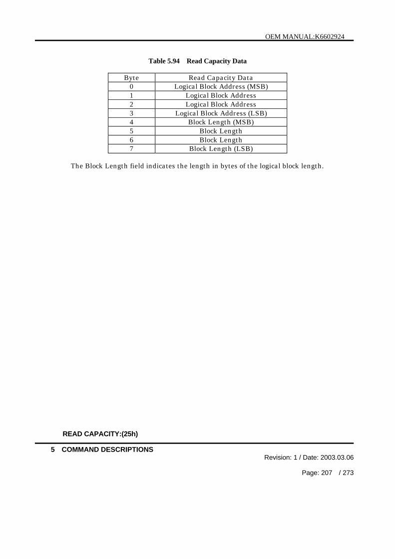
OEM MANUAL:K6602924
5 COMMAND DESCRIPTIONSRevision: 1 / Date: 2003.03.06
Page: 207 / 273
Table 5.94 Read Capacity Data
Byte Read Capacity Data0 Logical Block Address (MSB)1 Logical Block Address2 Logical Block Address3 Logical Block Address (LSB)4 Block Length (MSB)5 Block Length6 Block Length7 Block Length (LSB)
The Block Length field indicates the length in bytes of the logical block length.
READ CAPACITY:(25h)

OEM MANUAL:K6602924
5 COMMAND DESCRIPTIONSRevision: 1 / Date: 2003.03.06
Page: 208 / 273
5.15 READ DEFECT DATA:(37H)
BitByte
7 6 5 4 3 2 1 0
0 Operation Code (37H)0 0 1 1 0 1 1 1
1 Logical Unit Number Reserved0 0 0 0 0
2 Reserved P G Defect List Format0 0 0
3 Reserved0 0 0 0 0 0 0 0
4 Reserved0 0 0 0 0 0 0 0
5 Reserved0 0 0 0 0 0 0 0
6 Reserved0 0 0 0 0 0 0 0
7 Allocation Length (MSB)
8 Allocation Length (LSB)
9 Vendor Unique Reserved Flag Link0 0 0 0 0 0
The READ DEFECT DATA command requests the controller to transfer the defectdata of the medium to the host computer.
The Defect List Format field contains the same information as that specified in thebyte 1, bits 0-2 of the FORMAT UNIT command.The host computer can specify in this field the format of the defect list to betransferred from the controller.
Table 5.95 Defect List Format
No Bit Defect List Format2 1 0
1 0 X X Block Format2 1 0 0 Bytes from Index Format3 1 0 1 Physical Sector Format
Note 1 : X denotes a don’t care condition.
READ DEFECT DATA:(37h)

OEM MANUAL:K6602924
5 COMMAND DESCRIPTIONSRevision: 1 / Date: 2003.03.06
Page: 209 / 273
The P (Primary) bit set to 1 specifies that the controller is to return the primary listof defects. The P bit of 0 specifies that the controller must not return the primarylist of defects.
The G (Grown) bit set to 1 specifies that the controller is to return the grown list ofdefects. The G bit of 0 specifies that the controller must not return the G list ofdefects.
When both P and G bits are set to 1 simultaneously, the controller returns the P andG lists in that order.When both P and G bits are set to 0 simultaneously, the controller returns only thedefect list header.
The Allocation Length field specifies the number of bytes that the host computer hasallocated for returned Read Defect data. An allocation length of 0 specifies that noRead Defect data is to be transferred. The controller does not consider thiscondition as an error. Any other allocation length value specifies the maximumnumber of bytes that must be transferred. The controller terminates the Data Inphase when the number of bytes specified in the Allocation Length field have beentransferred or all available Read Defect data have been transferred to the hostcomputer, whichever is less.
The Read Defect data consists of a 4-byte header, followed by zero or more defectdescriptors.
Table 5.96 Read Defect Header
BitByte
7 6 5 4 3 2 1 0
0 Reserved0 0 0 0 0 0 0 0
1 Reserved P G Defect List Format0 0 0
2 Defect List Length (MSB)
3 Defect List Length (LSB)
The P and G bits are loaded with the same values that are stored in the CDB. TheDefect List Format field is loaded with the format of the defect descriptor.
The Defect List Length field specifies the total length in bytes of the subsequentdefect descriptors. This field = 0 specifies that no defect descriptor is to betransferred.
READ DEFECT DATA:(37h)

OEM MANUAL:K6602924
5 COMMAND DESCRIPTIONSRevision: 1 / Date: 2003.03.06
Page: 210 / 273
The Defect List Length field indicates a value that is four times larger than thenumber of defect descriptors for the block format and eight times larger than thenumber of defect descriptors for the byte format from index or the physical sectorformat, irrespective of the value of the Allocation Length value.
See Table 5.3, Table 5.4 and Table 5.5 in the subsection entitled “FORMAT UNIT” forthe defect descriptors.
The defect descriptor format for which the P lists are returned by this controller is inthe ascending order of the address (w/o case block format) but the defect descriptorformat for which the G lists are returned by this controller may not be in theascending order of the address.
The block addresses in the block format are physical block addresses.The physical block address is defined in Note 3 of Table 5.1.
Since the detection and registration method can be different per each defect listformat used, the number of defects transferred to the host can be different.
READ DEFECT DATA:(37h)

OEM MANUAL:K6602924
5 COMMAND DESCRIPTIONSRevision: 1 / Date: 2003.03.06
Page: 211 / 273
5.16 READ DEFECT DATA(12) :(B7H)
BitByte
7 6 5 4 3 2 1 0
0 Operation Code (B7H)1 0 1 1 0 1 1 1
1 Reserved P G Defect List Format0 0 0
2 Reserved0 0 0 0 0 0 0 0
3 Reserved0 0 0 0 0 0 0 0
4 Reserved0 0 0 0 0 0 0 0
5 Reserved0 0 0 0 0 0 0 0
6 Allocation Length (MSB)
7 Allocation Length
8 Allocation Length
9 Allocation Length (LSB)
10 Reserved0 0 0 0 0 0 0 0
11 Vendor Unique Reserved Flag Link0 0 0 0 0 0
The READ DEFECT DATA(12) command is the same as the READ DEFECTDATA command except that the READ DEFECT DATA(12) command has 4-bytelength of Allocation Length and 8-byte length of Read Defect Header as follows.
Refer to item 5.15 READ DEFECT DATA command in detail.
READ DEFECT DATA(12) :(B7h)

OEM MANUAL:K6602924
5 COMMAND DESCRIPTIONSRevision: 1 / Date: 2003.03.06
Page: 212 / 273
Table 5.97 Read Defect Header
BitByte
7 6 5 4 3 2 1 0
0 Reserved0 0 0 0 0 0 0 0
1 Reserved P G Defect List Format0 0 0
2 Reserved0 0 0 0 0 0 0 0
3 Reserved0 0 0 0 0 0 0 0
4 Defect List Length (MSB)
5 Defect List Length
6 Defect List Length
7 Defect List Length (LSB)
READ DEFECT DATA(12) :(B7h)

OEM MANUAL:K6602924
5 COMMAND DESCRIPTIONSRevision: 1 / Date: 2003.03.06
Page: 213 / 273
5.17 READ LONG:(3EH)
BitByte
7 6 5 4 3 2 1 0
0 Operation Code (3EH)0 0 1 1 1 1 1 0
1 Logical Unit Number Reserved CORRCT RelAdr0 0 0 0
2 Logical Block Address (MSB)
3 Logical Block Address
4 Logical Block Address
5 Logical Block Address (LSB)
6 Reserved0 0 0 0 0 0 0 0
7 Byte Transfer Length (MSB)
8 Byte Transfer Length (LSB)
9 Vendor Unique Reserved Flag Link0 0 0 0 0 0
The READ LONG command transfers the data and CRC/ECC bytes of the blockspecified in Logical Block Address to the host computer.The data transferred to the host computer may contain sets of data which consist ofuser data bytes (block length) , CRC/ECC bytes etc.
The CORRCT (Corrected) bit of 0 indicates that the controller transfers data startingat the block address specified in the Logical Block Address field without ECCcorrection.The CORRCT bit of 1 indicates that the controller transfers data after executing ECCcorrection.The Byte Transfer Length specifies the total number of transfer bytes of data bytes(block length) and other information bytes (CRC/ECC etc.).Byte Transfer Length of 0 indicates that no data is transferred. The controllerexecutes only seek operation to the track including the block specified by LogicalBlock Address.
READ LONG:(3Eh)
OEM MANUAL:K6602924
5 COMMAND DESCRIPTIONSRevision: 1 / Date: 2003.03.06
Page: 214 / 273
If the incorrect value is specified in Byte Transfer Length, the controller returnsCHECK CONDITION status with ILLEGAL REQUEST sense key. The ILI andValid bits are set to 1, and the difference of the requested length minus the actuallength in bytes is set to Information Byte. The negative values are indicated bytwo's complement notation.The host computer can calculate the correct Byte Transfer Length by subtracting theInformation Byte from the incorrect Byte Transfer Length.
READ LONG:(3Eh)

OEM MANUAL:K6602924
5 COMMAND DESCRIPTIONSRevision: 1 / Date: 2003.03.06
Page: 215 / 273
5.18 REASSIGN BLOCKS:(07H)
BitByte
7 6 5 4 3 2 1 0
0 Operation Code (07H)0 0 0 0 0 1 1 1
1 Logical Unit Number Reserved0 0 0 0 0
2 Reserved0 0 0 0 0 0 0 0
3 Reserved0 0 0 0 0 0 0 0
4 Reserved0 0 0 0 0 0 0 0
5 Vendor Unique Reserved Flag Link0 0 0 0 0 0
The REASSIGN BLOCKS command reassigns the defective logical blocks usingalternate spare sectors.
The host computer transfers a defect list containing the logical block addresses to bereassigned. The controller reassigns the physical blocks specified for each logicalblock address in the list. The data contained the logical blocks specified in the listare altered but the data in the other logical blocks are preserved.
If logical blocks that has previously been reassigned are specified for reassignment,they are assigned again.
If there is insufficient alternate spare area for reassigning the all specified defectivelogical blocks, the controller reassigns as any blocks as it can, terminates thecommand with a CHECK CONDITION status, and sets the sense key to“HARDWARE ERROR”. The controller sets the block address of the firstunassigned logical block in the command specific bytes of the sense data.
The Reassign Blocks defect list (Table 5.98) is loaded with a 4-byte header, followedby one or more defect descriptors.Each defect descriptor is four bytes long.
REASSIGN BLOCKS:(07h)
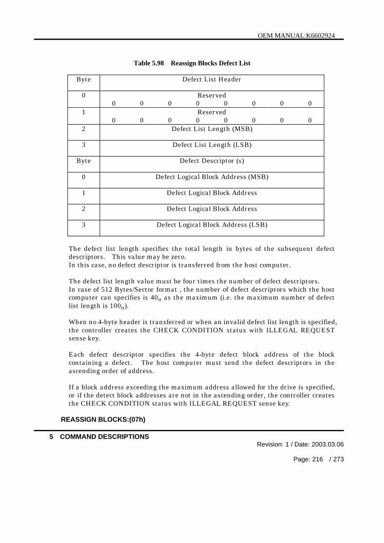
OEM MANUAL:K6602924
5 COMMAND DESCRIPTIONSRevision: 1 / Date: 2003.03.06
Page: 216 / 273
Table 5.98 Reassign Blocks Defect List
Byte Defect List Header
Reserved00 0 0 0 0 0 0 0
Reserved10 0 0 0 0 0 0 0
2 Defect List Length (MSB)
3 Defect List Length (LSB)
Byte Defect Descriptor (s)
0 Defect Logical Block Address (MSB)
1 Defect Logical Block Address
2 Defect Logical Block Address
3 Defect Logical Block Address (LSB)
The defect list length specifies the total length in bytes of the subsequent defectdescriptors. This value may be zero.In this case, no defect descriptor is transferred from the host computer.
The defect list length value must be four times the number of defect descriptors.In case of 512 Bytes/Sector format , the number of defect descriptors which the hostcomputer can specifies is 40H as the maximum (i.e. the maximum number of defectlist length is 100H).
When no 4-byte header is transferred or when an invalid defect list length is specified,the controller creates the CHECK CONDITION status with ILLEGAL REQUESTsense key.
Each defect descriptor specifies the 4-byte defect block address of the blockcontaining a defect. The host computer must send the defect descriptors in theascending order of address.
If a block address exceeding the maximum address allowed for the drive is specified,or if the detect block addresses are not in the ascending order, the controller createsthe CHECK CONDITION status with ILLEGAL REQUEST sense key.
REASSIGN BLOCKS:(07h)
OEM MANUAL:K6602924
5 COMMAND DESCRIPTIONSRevision: 1 / Date: 2003.03.06
Page: 217 / 273
The defects specified in the REASSIGN BLOCKS command are added to the G list(Grown Defect List) at the normal end of this command.
Precautions on the host computer side;When the information bytes of the sense data are reported as valid (Valid bit = 1),the host computer should issue another Reassign Blocks command with thereported block address added to the defect descriptors.
When the sense data is received with the logical block address (exceptFFFFFFFFH) in the command specific bytes, the host computer should issueanother Reassign Blocks command with the defect descriptors removed the defectblocks of less local block address number than the reported one.
REASSIGN BLOCKS:(07h)

OEM MANUAL:K6602924
5 COMMAND DESCRIPTIONSRevision: 1 / Date: 2003.03.06
Page: 218 / 273
5.19 RECEIVE DIAGNOSTIC RESULTS:(1CH)
BitByte
7 6 5 4 3 2 1 0
0 Operation Code (1CH)0 0 0 1 1 1 0 0
1 Logical Unit Number Reserved0 0 0 0 0
2 Reserved0 0 0 0 0 0 0 0
3 Allocation Length
4 Allocation Length
5 Vendor Unique Reserved Flag Link0 0 0 0 0 0
The RECEIVE DIAGNOSTIC RESULTS command requests the controller to returnthe results of the SEND DIAGNOSTIC command (see 5.29) to the host computerwhose SelfTest bit is set to 0. The results of the diagnostics are unpredictable if theSelfTest bit is set to 1.
The Allocation Length field specifies the number of bytes that the host computer hasallocated for returned diagnostic data. An allocation length of 0 specifies that nodiagnostic data is to be transferred.This condition must not be considered as an error. Any other allocation length valuespecifies the maximum number of bytes that must be transferred. The controllerterminates the Data In phase when the number of bytes specified in the AllocationLength field have been transferred or when all available diagnostic data have beentransferred to the host computer, whichever is less.
The diagnostic data is described in the description on the SEND DIAGNOSTICcommand. (See 5.29)
RECEIVE DIAGNOSTIC RESULTS:(1Ch)

OEM MANUAL:K6602924
5 COMMAND DESCRIPTIONSRevision: 1 / Date: 2003.03.06
Page: 219 / 273
5.20 RELEASE:(17H)
BitByte
7 6 5 4 3 2 1 0
0 Operation Code (17H)0 0 0 1 0 1 1 1
1 Logical Unit Number 3rdPty Third Party Device ID Extent0
2 Reservation Identification
3 Reserved0 0 0 0 0 0 0 0
4 Reserved0 0 0 0 0 0 0 0
5 Vendor Unique Reserved Flag Link0 0 0 0 0 0
The RELEASE command releases a logical unit that is previously reserved by a hostcomputer. No error must be informed if a RELEASE command is issued to a logicalunit that is not reserved.
The Extent bit must always be set to 0 as this SCSI controller does not support theextent release feature. If this condition is violated, the controller creates theCHECK CONDITION status with ILLEGAL REQUEST sense key.
The controller ignores the Reservation Identification that is used by the extentrelease feature.
(1) Logical unit releaseThe RELEASE command releases the logical unit that is reserved by thecurrent host computer.
(2) Third party releaseThe third-party release feature of the Release command allows the hostcomputer to release a logical unit that is reserved by the third party reservationfeature.When the 3rdPty (Third Party) bit is set to 0, the third party release feature isdisabled. In this case, the controller ignores the Third Party Device ID field.When the 3rdPty bit is set to 1, the controller releases the logical unit from thereserved state provided that the reservation has been carried out by the samehost computer on the same SCSI device specified in the Third Party Device IDfield.The Third Party Device ID field contains the SCSI ID for the SCSI device torelease the logical unit.
RELEASE:(17h)

OEM MANUAL:K6602924
5 COMMAND DESCRIPTIONSRevision: 1 / Date: 2003.03.06
Page: 220 / 273
5.21 RELEASE(10):(57H)
BitByte
7 6 5 4 3 2 1 0
0 Operation Code (57H)0 1 0 1 0 1 1 1
1 Logical Unit Number 3rdPty Reserved Extent0 0 0 0
2 Reservation Identification
3 Third Party Device ID
4 Reserved0 0 0 0 0 0 0 0
5 Reserved0 0 0 0 0 0 0 0
6 Reserved0 0 0 0 0 0 0 0
7 Parameter List Length(MSB)
8 Parameter List Length(LSB)
9 Vendor Unique Reserved Flag Link0 0 0 0 0 0
The RELEASE(10) command is the same as the RELEASE command (see 5.20)expect that the RELEASE(10) command has 1-byte length of Third Party Device ID. If the RELEASE(10) command is implemented, then the RESERVE(10) also shall beimplemented.
RELEASE(10):(57h)
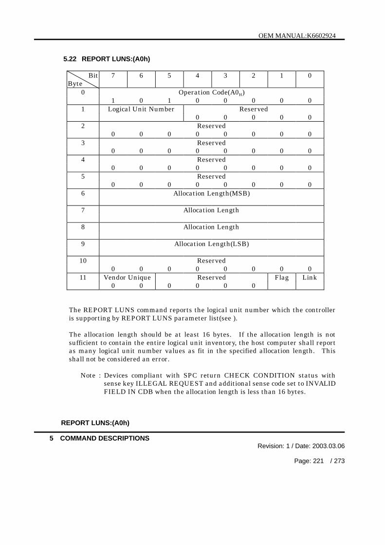
OEM MANUAL:K6602924
5 COMMAND DESCRIPTIONSRevision: 1 / Date: 2003.03.06
Page: 221 / 273
5.22 REPORT LUNS:(A0h)
BitByte
7 6 5 4 3 2 1 0
0 Operation Code(A0H)1 0 1 0 0 0 0 0
1 Logical Unit Number Reserved0 0 0 0 0
2 Reserved0 0 0 0 0 0 0 0
3 Reserved0 0 0 0 0 0 0 0
4 Reserved0 0 0 0 0 0 0 0
5 Reserved0 0 0 0 0 0 0 0
6 Allocation Length(MSB)
7 Allocation Length
8 Allocation Length
9 Allocation Length(LSB)
10 Reserved0 0 0 0 0 0 0 0
11 Vendor Unique Reserved Flag Link0 0 0 0 0 0
The REPORT LUNS command reports the logical unit number which the controlleris supporting by REPORT LUNS parameter list(see ).
The allocation length should be at least 16 bytes. If the allocation length is notsufficient to contain the entire logical unit inventory, the host computer shall reportas many logical unit number values as fit in the specified allocation length. Thisshall not be considered an error.
Note : Devices compliant with SPC return CHECK CONDITION status withsense key ILLEGAL REQUEST and additional sense code set to INVALIDFIELD IN CDB when the allocation length is less than 16 bytes.
REPORT LUNS:(A0h)

OEM MANUAL:K6602924
5 COMMAND DESCRIPTIONSRevision: 1 / Date: 2003.03.06
Page: 222 / 273
Table 5.99 REPORT LUNS Parameter List Format
BitByte
7 6 5 4 3 2 1 0
0 (MSB)• LUN List Length(N-7)•3 (LSB)4• Reserved•7
LUN List
8 (MSB)• First LUN•15 (LSB)• •• •• •
N-7 (MSB)• Last LUN•N (LSB)
The controller supports only the logical unit number 0, first LUN in LUN list0000000000000000H are reported.
REPORT LUNS:(A0h)

OEM MANUAL:K6602924
5 COMMAND DESCRIPTIONSRevision: 1 / Date: 2003.03.06
Page: 223 / 273
5.23 REQUEST SENSE:(03H)
BitByte
7 6 5 4 3 2 1 0
0 Operation Code (03H)0 0 0 0 0 0 1 1
1 Logical Unit Number Reserved0 0 0 0 0
2 Reserved0 0 0 0 0 0 0 0
3 Reserved0 0 0 0 0 0 0 0
4 Allocation Length
5 Vendor Unique Reserved Flag Link0 0 0 0 0 0
The REQUEST SENSE command returns the sense data of the unit describing theCHECK CONDITION status indicated to the host computer. The sense data is heldpending in the controller so that it may be transferred to the host computer.This sense data is cleared when the unit in the check state receives a new commandfrom the host computer that received the CHECK CONDITION status.
The allocation length specifies the number of bytes to be allocated by the hostcomputer for the sense data to be transferred. The other allocation length valuesspecify the maximum number of bytes to be transferred. The controller terminatesthe Data In phase when it has transferred the number of sense data bytes specifiedby the allocation length or all sense data bytes, whichever is shorter.
This command returns the Check Condition status only when one of the followingfatal errors occurs
· The controller receives a non-zero reserved bit n the CDB.
· The controller detects an unrecoverable parity error on the data bus.
· The sense data transfer is prevented by a controller error.
The sense data transferred when a fatal error occurred during a REQUEST SENSEcommand is invalid.
The sense data transferred by this SCSI controller is all in the extended sense format(see Chapter 6, “SENSE DATA” for the extended sense data).
REQUEST SENSE:(03h)

OEM MANUAL:K6602924
5 COMMAND DESCRIPTIONSRevision: 1 / Date: 2003.03.06
Page: 224 / 273
5.24 RESERVE:(16H)
BitByte
7 6 5 4 3 2 1 0
0 Operation Code (16H)0 0 0 1 0 1 1 0
1 Logical Unit Number 3rdPty Third Party Device ID Extent0
2 Reservation Identification
3 Extent List Length (MSB)
4 Extent List Length (LSB)
5 Vendor Unique Reserved Flag Link0 0 0 0 0 0
The RESERVE command reserves a logical unit for the host computer issuing thiscommand. The third-party reservation feature allows the logical unit to be reservedfor another specified SCSI device.
The RESERVE and RELEASE commands provide the basic mechanism for resolvingcontentions that can occur in multi-host (initiator) systems.
Since this SCSI controller does not support the extended reservation feature, theExtent bit must always be set to 0. If this is not observed, the controller creates theCHECK CONDITION status with ILLEGAL REQUEST sense key.
The controller ignores the Reservation Identification and Extent List Length fieldsthat are used by the extent reservation feature. Accordingly, no Data Out phase canoccur.
(1) Logical unit reservationThe RESERVE command requests the controller to reserve the specified logicalunit so that the host computer can use the entire logical unit exclusively untilthe reservation is superseded by another valid RESERVE command issued bythe same host computer or until the reservation is released by a RELEASEcommand from the same host computer, by a Bus Device Reset message fromanother host computer, or by a hardware reset.
A logical unit reservation is rejected with the RESERVATION CONFLICTstatus set if the specified logical unit has already been reserved by another hostcomputer. In this case, the reservation request is not queued into thecontroller (the RESERVE command itself is queued, however).
RESERVE:(16h)

OEM MANUAL:K6602924
5 COMMAND DESCRIPTIONSRevision: 1 / Date: 2003.03.06
Page: 225 / 273
The host computer can reserve any logical unit that has been reserved by thesame host computer.Once a reservation is established, if another host computer issues a commandother than the INQUIRY, REQUEST SENSE or RELEASE command to thereserved logical unit, that command is rejected with the RESERVATIONCONFLICT status set.
(2) Third party reservationThe third-party reservation feature of the RESERVE command allows the hostcomputer to reserve a logical unit for another specified SCSI device. Thisfeature is applicable to multi-host systems that use the COPY command. (TheCOPY command proper is executed by another SCSI controller. )
Third party reservation is disabled when the 3rdPty (Third Party) bit is set to 0.In this case, the controller ignores the Third Party Device ID field.
When the 3rdPty bit is set to 1, the controller reserves the logical unit foranother SCSI device specified in the Third Party Device ID field.
The Third Party Device ID field contains the SCSI ID for another SCSI deviceto be reserved as the logical unit.
Third Party reservation processing proceeds in the same way as in logical unitreservation except that it allows another SCSI device to reserve the logical unit.
This SCSI controller releases a third party reservation when it receives a validRESERVE command from the same host computer (superseding reservation),when it receives a third party Release command specifying the same third partydevice ID, when it receives a BUS DEVICE RESET message from any hostcomputer, or when a hardware reset condition occurs.
(3) Superseding reservationThe host computer that retains a logical unit reservation can change thereservation status by issuing another RESERVE command. This supersedingRESERVE command releases the old reservation state when the newreservation request is allowed. If the new reservation request is not accepted,the old reservation state is preserved. If the superseding reservation conflictswith the preceding active reservation state (other thanthe reservation being superseded), the controller rejects this command with theRESERVATION CONFLICT status.
The primary purpose of superseding reservation is to change the SCSI deviceID in the third party reservation state.This feature is made available for the COPY command that is used betweendifferent SCSI devices.
RESERVE:(16h)
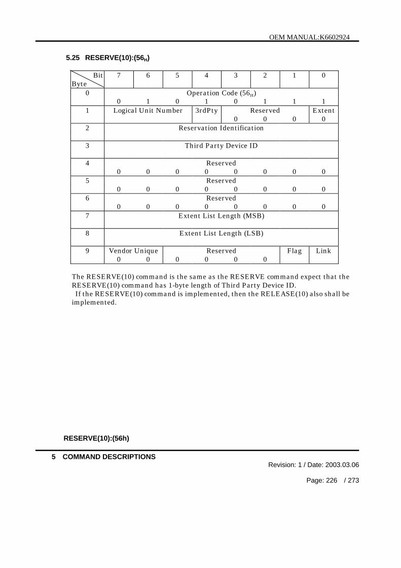
OEM MANUAL:K6602924
5 COMMAND DESCRIPTIONSRevision: 1 / Date: 2003.03.06
Page: 226 / 273
5.25 RESERVE(10):(56H)
BitByte
7 6 5 4 3 2 1 0
0 Operation Code (56H)0 1 0 1 0 1 1 1
1 Logical Unit Number 3rdPty Reserved Extent0 0 0 0
2 Reservation Identification
3 Third Party Device ID
4 Reserved0 0 0 0 0 0 0 0
5 Reserved0 0 0 0 0 0 0 0
6 Reserved0 0 0 0 0 0 0 0
7 Extent List Length (MSB)
8 Extent List Length (LSB)
9 Vendor Unique Reserved Flag Link0 0 0 0 0 0
The RESERVE(10) command is the same as the RESERVE command expect that theRESERVE(10) command has 1-byte length of Third Party Device ID. If the RESERVE(10) command is implemented, then the RELEASE(10) also shall beimplemented.
RESERVE(10):(56h)

OEM MANUAL:K6602924
5 COMMAND DESCRIPTIONSRevision: 1 / Date: 2003.03.06
Page: 227 / 273
5.26 REZERO UNIT:(01H)
BitByte
7 6 5 4 3 2 1 0
0 Operation Code (01H)0 0 0 0 0 0 0 1
1 Logical Unit Number Reserved0 0 0 0 0
2 Reserved0 0 0 0 0 0 0 0
3 Reserved0 0 0 0 0 0 0 0
4 Reserved0 0 0 0 0 0 0 0
5 Vendor Unique Reserved Flag Link0 0 0 0 0 0
The REZERO UNIT command is used to recover from errors such as seek errorsoccurring in the selected disk drive. This error recovery command positions theread/write head in the home position (physical cylinder 0, head 0).
REZERO UNIT:(01h)

OEM MANUAL:K6602924
5 COMMAND DESCRIPTIONSRevision: 1 / Date: 2003.03.06
Page: 228 / 273
5.27 SEEK:(0BH)
BitByte
7 6 5 4 3 2 1 0
0 Operation Code (0BH)0 0 0 0 1 0 1 1
1 Logical Unit Number Logical Block Address (MSB)
2 Logical Block Address
3 Logical Block Address (LSB)
4 Reserved0 0 0 0 0 0 0 0
5 Vendor Unique Reserved Flag Link0 0 0 0 0 0
The SEEK command positions the read/write head on the track containing the blockthat is specified in the logical block address field.
The controller terminates the command with a CHECK CONDITION status andwith the “ILLEGAL REQUEST” sense key if an invalid logical block address isspecified (see Note). For other errors, the controller terminates the command withthe CHECK CONDITION status and the appropriate sense key.
Note : The information byte field of the sense data is loaded with the last logicalblock address.
SEEK:(0Bh)
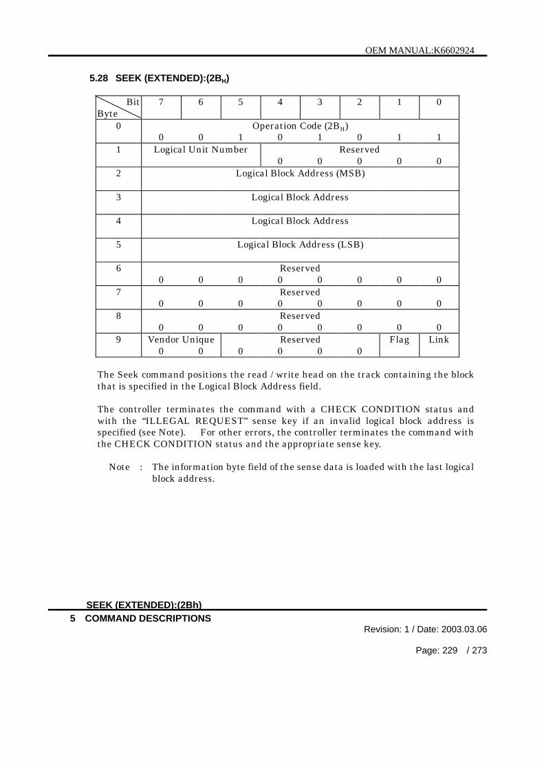
OEM MANUAL:K6602924
5 COMMAND DESCRIPTIONSRevision: 1 / Date: 2003.03.06
Page: 229 / 273
5.28 SEEK (EXTENDED):(2BH)
BitByte
7 6 5 4 3 2 1 0
0 Operation Code (2BH)0 0 1 0 1 0 1 1
1 Logical Unit Number Reserved0 0 0 0 0
2 Logical Block Address (MSB)
3 Logical Block Address
4 Logical Block Address
5 Logical Block Address (LSB)
6 Reserved0 0 0 0 0 0 0 0
7 Reserved0 0 0 0 0 0 0 0
8 Reserved0 0 0 0 0 0 0 0
9 Vendor Unique Reserved Flag Link0 0 0 0 0 0
The Seek command positions the read / write head on the track containing the blockthat is specified in the Logical Block Address field.
The controller terminates the command with a CHECK CONDITION status andwith the “ILLEGAL REQUEST” sense key if an invalid logical block address isspecified (see Note). For other errors, the controller terminates the command withthe CHECK CONDITION status and the appropriate sense key.
Note : The information byte field of the sense data is loaded with the last logicalblock address.
SEEK (EXTENDED):(2Bh)

OEM MANUAL:K6602924
5 COMMAND DESCRIPTIONSRevision: 1 / Date: 2003.03.06
Page: 230 / 273
5.29 SEND DIAGNOSTIC:(1DH)
BitByte
7 6 5 4 3 2 1 0
0 Operation Code (1DH)0 0 0 1 1 1 0 1
1 Self-Test Code PF R SelfTest DevOfL UnitOfL
0 02 Reserved
0 0 0 0 0 0 0 03 Parameter List Length (MSB)
4 Parameter List Length (LSB)
5 Vendor Unique Reserved Flag Link0 0 0 0 0 0
The SEND DIAGNOSTIC command requests the controller to perform diagnostics onthe controller and the selected logical unit.
When the SelfTest bit is one the Self-Test Code field shall contain (000)b. When theSelfTest bit is zero, the contents of Self-Test Code field are specified in Table 5.100.
Table 5.100 Self-Test Code Field Values
Self-TestCode
Name Description
(000)b - This value shall be used when the SelfTest bit is set toone or if the SEND DIAGNOSTIC command is notinvoking one of the other self-test functions such asenclosure services(see SES) or the Traslate Addresspage.
(001)b Background shortself-test
The device server shall start its short self-test in thebackground mode. The Parameter List Length fieldshall contain zero.
(010)b Background extendedself-test
The device server shall start its extended self-test inthe background mode. The Parameter List Length fieldshall contain zero.
(011)b Reserved (cont’d)
SEND DIAGNOSTIC:(1Dh)

OEM MANUAL:K6602924
5 COMMAND DESCRIPTIONSRevision: 1 / Date: 2003.03.06
Page: 231 / 273
Table 5.100 Self-Test Code Field Values (cont’d)
(100)b Abortbackground self-test
The device server shall abort the current self-testrunning in background mode. The Parameter ListLength field shall contain zero. This value is only validif a previous SEND DIAGNOSTIC command specifieda background self-test function and that self-test hasnot completed. If either or these conditions is not met,then the device server shall return a CHECKCONDITION status with a sense key of ILLEGALREQUEST and an additional sense code of INVALIDFIELD IN CDB.
(101)b Foreground shortself-test
The device server shall start its short self-test in theforeground mode. The Parameter List Length fieldshall contain zero.
(110)b Foreground extendedself-test
The device server shall start its extended self-test inthe foreground mode. The Parameter List Length fieldshall contain zero.
(111)b Reserved
The controller carries out the default self-diagnostics if the SelfTest (Self Test) bit ofthe command is set to 1. In this case, the Parameter List Length field must be set to0.When the self-diagnostics are completed normally, the controller terminates thecommand with the GOOD status. Otherwise, the controller terminates thecommand with a CHECK CONDITION status and sets the sense key to“HARDWARE ERROR” .The results of the self-diagnostics are not returned to the host computer respondingto the RECEIVE DIAGNOSTIC RESULTS command. (see 5.19)
When the SelfTest bit is set to 0, the controller carries out the diagnostics specified inthe diagnostic parameters (listed in Table 5.101).
If the DevOfL (SCSI Device Offline) bit is set to 1, the controller is allowed to havea bad influence on operations to other logical unit on the controller.If the DevOfL bit is set to 0, the information of operations to other logical unit onthe controller is preserved. The controller only supports DevOfL bit = 0.The PF (Page Format) bit of 1 specifies that diagnostic parameters are defined inpage format. The PF bit of 0 specifies that diagnostic parameters are not defined inpage format (they are defined in vender unique format ).
SEND DIAGNOSTIC:(1Dh)

OEM MANUAL:K6602924
5 COMMAND DESCRIPTIONSRevision: 1 / Date: 2003.03.06
Page: 232 / 273
When the UnitOfL (Logical Unit Offline) bit is set to 1, the controller performsdiagnostics that enables write operations on user medium or operation that affectuser visible medium positioning.When the UnitOfL bit is set to 0, the diagnostics that enables write operations onuser medium or operations that affect user visible medium positioning are inhibited.
The Parameter List Length field specifies the length in bytes of the diagnosticparameters to be transferred during the Data Out phase.The host computer must set this field to 0 if the SelfTest bit is set to 1. If theSelfTest bit is set to 0, the Parameter List Length field must be set to a value greaterthan or equal to 6H. If this condition is not met, the controller creates the CHECKCONDITION status with ILLEGAL REQUEST sense key.
The contents of diagnostic parameter list are written in (1) Page Format diagnosticparameter and (2) Vender Unique diagnostic parameter.
(1) Page Format diagnostic parameterThe diagnostic parameters commonly used by the Send Diagnostic and ReceiveDiagnostic Results commands are shown in Table 5.101, defined when the PF bit isset to 1.
For the Send Diagnostic command, the Parameter List Length specifies thenumber of diagnostic parameter bytes. The Parameter List Length of 0 indicatesthat no diagnostic parameter is transferred. The controller does not handle thiscondition as an error ( no operation ). The host computer may transfer one page ofdata as a diagnostic parameter.
If any shortage of parameters or multiple-page transfer occurs, the controllerreturns the CHECK CONDITION status with ILLEGAL REQUEST sense key.
For the Receive Diagnostic Results command, the Allocation Length specifies thenumber of diagnostic parameter bytes.

OEM MANUAL:K6602924
5 COMMAND DESCRIPTIONSRevision: 1 / Date: 2003.03.06
Page: 233 / 273
Table 5.101 Diagnostic Page Format
BitByte
7 6 5 4 3 2 1 0
0 Page Code
1 Reserved0 0 0 0 0 0 0 0
2 Page Length (MSB)
3 Page Length (LSB)
4to Diagnostic Parametersn
The Page Code specifies either specification (in case of Send Diagnostic command)or report (in case of Receive Diagnostic Results command). The controllersupports the following pages.
Page Code Description00H Supported Diagnostic Page40H Translate Address Page
When any other page code than shown above is specified, the controller returnsCHECK CONDITION status with the ILLEGAL REQUEST sense key.
The Page Length specifies the number of bytes that follow the Page Length field.
SEND DIAGNOSTIC:(1Dh)

OEM MANUAL:K6602924
5 COMMAND DESCRIPTIONSRevision: 1 / Date: 2003.03.06
Page: 234 / 273
Table 5.102 Supported Diagnostic Page (Code = 00H)
Bit 7 6 5 4 3 2 1 0Byte
0 Page Code0 0 0 0 0 0 0 0
1 Reserved0 0 0 0 0 0 0 0
2 Page Length (MSB)0 0 0 0 0 0 0 0
3 Page Length (LSB)0 0 0 0 0 1 0 0
Supported Page List
4 00H (Supported Diagnostic)
5 40H (Translate Address)
6 Reserved0 0 0 0 0 0 0 0
7 Reserved0 0 0 0 0 0 0 0
For the Send Diagnostic command, the Page Length must be specified to 0. Ifany value other than 0 is specified, the controller returns the Check Conditionstatus with the Illegal Request Sense Key.
For the Receive Diagnostic Results command, the controller sets the PageLength to 0004H and reports the codes 00H (Supported Diagnostic Page) and 40H
(Translate Address Page).
SEND DIAGNOSTIC:(1Dh)

OEM MANUAL:K6602924
5 COMMAND DESCRIPTIONSRevision: 1 / Date: 2003.03.06
Page: 235 / 273
Table 5.103 Translate Address Page (Code = 40H)
(in case of Send Diagnostic command)Bit 7 6 5 4 3 2 1 0
Byte0 Page Code
0 1 0 0 0 0 0 01 Reserved
0 0 0 0 0 0 0 02 Page Length (MSB)
0 0 0 0 0 0 0 03 Page Length (LSB)
0 0 0 0 1 0 1 04 Reserved Supplied Format
0 0 0 0 05 Reserved Translate Format
0 0 0 0 06to Address to Translate13
The Page Length must be set to 000AH. If any value other than 000AH is set, thecontroller returns the Check Condition status with the Illegal Request SenseKey.
The selectable combination of Supplied Format (before translation) andTranslate Format (after translation) is shown as below.
Table 5.104 Translation Format
Supplied Format Translate FormatCode Format Code Format0XX Logical Block Address 101 Physical Sector Address101 Physical Sector Address 0XX Logical Block Address
(Note) A bit of X denotes “do not care” condition.
The above codes are identical with those of the Defect List Format in theFormat Unit command (see 5.1). But the sector number shown in the PhysicalSector Address has no fixed relation to the physical location from the indexsignal since the controller uses ID information on this sector.
If any other translation than defined above is specified, the controller returnsthe Check Condition with the Illegal Request Sense Key.
SEND DIAGNOSTIC:(1Dh)

OEM MANUAL:K6602924
5 COMMAND DESCRIPTIONSRevision: 1 / Date: 2003.03.06
Page: 236 / 273
When the Supplied Format is the Logical Block Address, the byte 6 to 9 ofAddress to Translate field specifies a logical block address in Block Format (seeTable 5.3 in Format Unit command). The byte 10 to 13 of the field must be setto 00000000H.
When the Supplied Format is the Physical Sector Address, the byte 6 to 13 ofAddress to Transfer field specifies a physical block address in Physical sectorFormat (see Table 5.5 in Format Unit command).
If any invalid logical block address or non-zero value of byte 10 to 13 is specified,the controller returns the Check Condition status with the Illegal RequestSense Key.
Table 5.105 Read Alternate Page (Code = 40H)
(in case of Receive Diagnostic Results command)Bit 7 6 5 4 3 2 1 0
Byte0 Page Code
0 1 0 0 0 0 0 01 Reserved
0 0 0 0 0 0 0 02 Page Length (MSB)
3 Page Length (LSB)
4 Reserved Supplied Format0 0 0 0 0
5 RAREA ALTSEC ALTTRK Reserved Translated Format0 0
6to Translated Address 11314to Translated Address 2 (if required)21··· ···nto Translated Address n (if required)
n+7
SEND DIAGNOSTIC:(1Dh)

OEM MANUAL:K6602924
5 COMMAND DESCRIPTIONSRevision: 1 / Date: 2003.03.06
Page: 237 / 273
The Page Length indicates the number of bytes that follow the Page Lengthfield.
The Supplied Format indicates the code sent by the Send Diagnostic command.
The RAREA (Reserved Area) bit of 1 indicates that a part or the whole ofaddress-translated block locates in the reserved area of medium (the areainaccessible by the host using logical block address).The RAREA bit of 0 indicates that the whole address-translated block does notlocate in the reserved area of medium.
The ALTSEC (Alternate Sector) bit of 1 indicates that a part or the whole ofaddress-translated blocks is reallocated to an alternate sector in medium(except sector slipping reallocation).The ALTSEC bit of 0 indicates that the whole of address-translated block is notreallocated to an alternate sector in medium (except sector slippingreallocation).
The ALTTRK (Alternate Track) bit of 1 indicates that a part or the whole ofaddress-translated blocks is reallocated to an alternate track in medium.The ALTTRK bit of 0 indicates that the whole of address-translated block is notreallocated to an alternate track in medium.
But when the sector specified by Send Diagnostic command is an original sectoror a replacement sector in specified track, RAREA and ALTSEC bit valuesreported from the controller are indecisive.
The Translated Address 1 to n indicate the address after translation. Forinstance, if the logical block consists of two physical sectors, the addresses forthese two sectors are indicated accordingly.
(2) Vender Unique diagnostic parameterThe diagnostic parameters whose the PF bit is set to 0 are shown in Table 5.106and Table 5.107.
Table 5.106 Diagnostic Parameter List
Byte Diagnostic Control Bytes0 Sub Command Code
1-4 Refer to Sub Command Definition5 Control Byte
Diagnostic Data6-n Refer to Sub Command Definition
SEND DIAGNOSTIC:(1Dh)

OEM MANUAL:K6602924
5 COMMAND DESCRIPTIONSRevision: 1 / Date: 2003.03.06
Page: 238 / 273
The results of the diagnostics specified in the vender unique diagnostic parametersare reported to the host computer by the RECEIVE DIAGNOSTIC RESULTScommand. The SEND DIAGNOSTIC command terminates with the GOODstatus whether the result of diagnostics is successful or not (normal or abnormaltermination).
The sub command code identifies the diagnostic function to be carried out by thecontroller. Some sub commands are not executed if its UnitOfL bit is set to 0.
Table 5.107 Sub Command Codes
No. UnitOfL Bit Sub Command Function0 1 Code
1 X X 00H No Operation2 X 02H Read Long3 X 03H Write Long4 X 07H Physical Read5 X 08H Physical Write
If a sub command code is specified on condition that UnitOfL bit is set to the valuewithout X marked in Table 5.67, the controller creates the CHECK CONDITIONstatus with ILLEGAL REQUEST sense key.If an invalid sub command code is specified, the controller creates the CHECKCONDITION status with ILLEGAL REQUEST sense key.
SEND DIAGNOSTIC:(1Dh)

OEM MANUAL:K6602924
5 COMMAND DESCRIPTIONSRevision: 1 / Date: 2003.03.06
Page: 239 / 273
5.30 START / STOP UNIT:(1BH)
BitByte
7 6 5 4 3 2 1 0
0 Operation Code (1BH)0 0 0 1 1 0 1 1
1 Logical Unit Number Reserved Immed0 0 0 0
2 Reserved0 0 0 0 0 0 0 0
3 Reserved0 0 0 0 0 0 0 0
4 Reserved Start0 0 0 0 0 0 0
5 Vendor Unique Reserved Flag Link0 0 0 0 0 0
The START/STOP command specifies whether the logical unit is to be made ready ornot ready for the subsequent operations.
When the Immed (Immediate) bit is set to 1, the controller returns the statusimmediately after starting an operation (Spin Up / Down).
When the Immed bit is set to 0, the controller returns the status on completion of theoperation.
When the Start bit is set to 1, the controller sets the logical unit ready.
When the Start bit is set to 0, the controller sets the logical unit not ready.
START / STOP UNIT:(1Bh)

OEM MANUAL:K6602924
5 COMMAND DESCRIPTIONSRevision: 1 / Date: 2003.03.06
Page: 240 / 273
5.31 SYNCHRONIZED CACHE:(35H)
BitByte
7 6 5 4 3 2 1 0
0 Operation Code (35H)0 0 1 1 0 1 0 1
1 Logical Unit Number Reserved Immed RelAdr0 0 0 0
2 Logical Block Address (MSB)
3 Logical Block Address
4 Logical Block Address
5 Logical Block Address (LSB)
6 Reserved0 0 0 0 0 0 0 0
7 Transfer Length (MSB)
8 Transfer Length (LSB)
9 Vendor Unique Reserved Flag Link0 0 0 0 0 0
The SYNCHRONIZED CACHE command requests the controller to write theunwritten data in the cache memory, within the range specified in the TransferLength, starting at the block address specified in the Logical Block Address field., tothe disk.
The Transfer Length of 0 indicates that all remaining logical blocks on the logicalunit shall be within the range.
If the Immed (Immediate) bit is set to 1, the controller returns GOOD status as soonas the CDB is received.If the Immed bit is set to 0, the command terminates after the all unwritten data inthe cache memory is finished writing to the medium.
SYNCHRONIZED CACHE:(35h)

OEM MANUAL:K6602924
5 COMMAND DESCRIPTIONSRevision: 1 / Date: 2003.03.06
Page: 241 / 273
5.32 TEST UNIT READY:(00H)
BitByte
7 6 5 4 3 2 1 0
0 Operation Code (00H)0 0 0 0 0 0 0 0
1 Logical Unit Number Reserved0 0 0 0 0
2 Reserved0 0 0 0 0 0 0 0
3 Reserved0 0 0 0 0 0 0 0
4 Reserved0 0 0 0 0 0 0 0
5 Vendor Unique Reserved Flag Link0 0 0 0 0 0
The TEST UNIT READY command checks whether the selected drive is ready or not.The controller responds to this command with a GOOD status when the selecteddrive has been powered on and in the ready state (ready to write to and read from itsdisk storage).Otherwise, the controller returns a status according to the drive state.
TEST UNIT READY:(00h)

OEM MANUAL:K6602924
5 COMMAND DESCRIPTIONSRevision: 1 / Date: 2003.03.06
Page: 242 / 273
5.33 VERIFY:(2FH)
BitByte
7 6 5 4 3 2 1 0
0 Operation Code (2FH)0 0 1 0 1 1 1 1
1 Logical Unit Number DPO Reserved BytChk RelAdr0 0 0
2 Logical Block Address (MSB)
3 Logical Block Address
4 Logical Block Address
5 Logical Block Address (LSB)
6 Reserved0 0 0 0 0 0 0 0
7 Verification Length (MSB)
8 Verification Length (LSB)
9 Vendor Unique Reserved Flag Link0 0 0 0 0 0
The VERIFY command verifies the data in the number of consecutive data blocksspecified in the Transfer Length field, starting at the block address specified in theLogical Block Address field.
The DPO (Disable Page Out) bit is ignored.
When the BytChk (Byte Check) bit is set to 0, the controller does not request theverification data but verifies the written data in the medium using ECC. When theBytChk bit is set to 1, the controller performs byte-by-byte compare check betweenthe written data in the medium and the transferred data from the host computer.
A verification Length of 0 specifies that no logical block is to be verified. Thecontroller in this case only seeks to the track containing the block specified in theLogical Block Address.
VERIFY:(2Fh)

OEM MANUAL:K6602924
5 COMMAND DESCRIPTIONSRevision: 1 / Date: 2003.03.06
Page: 243 / 273
The controller terminates the command with a CHECK CONDITION status andwith the “ILLEGAL REQUEST” sense key if an invalid logical block address isspecified (see Note). For other errors, the controller terminates the command withthe CHECK CONDITION status and the appropriate sense key.
Note : The information byte field of the sense data is loaded with the last logicalblock address.
VERIFY:(2Fh)

OEM MANUAL:K6602924
5 COMMAND DESCRIPTIONSRevision: 1 / Date: 2003.03.06
Page: 244 / 273
5.34 WRITE:(0AH)
BitByte
7 6 5 4 3 2 1 0
0 Operation Code (0AH)0 0 0 0 1 0 1 0
1 Logical Unit Number Logical Block Address (MSB)
2 Logical Block Address
3 Logical Block Address (LSB)
4 Transfer Length
5 Vendor Unique Reserved Flag Link0 0 0 0 0 0
The WRITE command writes the number of consecutive data blocks from the hostcomputer specified in the transfer length field to the medium starting at the blockaddress specified in the logical block address field.
When a 0 is specified in the transfer length field, 256 blocks of data are transferred.
The controller terminates the command with a CHECK CONDITION status andwith the “ILLEGAL REQUEST” sense key if an invalid logical block address isspecified (see Note). For other errors, the controller terminates the command withthe CHECK CONDITION status and the appropriate sense key.
Note : The information byte field of the sense data is loaded with the last logicalblock address.
WRITE:(0Ah)

OEM MANUAL:K6602924
5 COMMAND DESCRIPTIONSRevision: 1 / Date: 2003.03.06
Page: 245 / 273
5.35 WRITE (EXTENDED):(2AH)
BitByte
7 6 5 4 3 2 1 0
0 Operation Code (2AH)0 0 1 0 1 0 1 0
1 Logical Unit Number DPO FUA Reserved RelAdr0 0 0
2 Logical Block Address (MSB)
3 Logical Block Address
4 Logical Block Address
5 Logical Block Address (LSB)
6 Reserved0 0 0 0 0 0 0 0
7 Transfer Length (MSB)
8 Transfer Length (LSB)
9 Vendor Unique Reserved Flag Link0 0 0 0 0 0
The WRITE command writes the number of consecutive data blocks from the hostcomputer specified in the Transfer Length field to the medium starting at the blockaddress specified in the Logical Block Address field.
The DPO (Disable Page Out) bit is used to determine the priority of the logical blockdata read by this command in the cache.But in this controller, the priority of the retained data is controlled by the value of theRetention Priority field in the mode page 8 (Caching Page; refer to Table 5.36) or thealgorithm implementing the cache replacement strategy irrespective of DPO bit.
If the FUA (Force Unit Access) bit is set to 1, the controller returns the status oncompletion of writing to the medium.If the FUA bit is set to 0, the controller returns the status prior to writing to themedium.
A Transfer Length of 0 specifies that no logical block is to be transferred. Thecontroller in this case only seeks to the track containing the block specified in theLogical Block Address.
WRITE (EXTENDED):(2Ah)

OEM MANUAL:K6602924
5 COMMAND DESCRIPTIONSRevision: 1 / Date: 2003.03.06
Page: 246 / 273
The controller terminates the command with a CHECK CONDITION status andwith the “ILLEGAL REQUEST” sense key if an invalid logical block address isspecified (see Note ).
For other errors, the controller terminates the command with the CHECKCONDITION status and the appropriate sense key.
Note : The information byte field of the sense data is loaded with the last logicalblock address.
WRITE (EXTENDED):(2Ah)

OEM MANUAL:K6602924
5 COMMAND DESCRIPTIONSRevision: 1 / Date: 2003.03.06
Page: 247 / 273
5.36 WRITE AND VERIFY:(2EH)
BitByte
7 6 5 4 3 2 1 0
0 Operation Code (2EH)0 0 1 0 1 1 1 0
1 Logical Unit Number DPO Reserved BytChk RelAdr0 0 0
2 Logical Block Address (MSB)
3 Logical Block Address
4 Logical Block Address
5 Logical Block Address (LSB)
6 Reserved0 0 0 0 0 0 0 0
7 Transfer Length (MSB)
8 Transfer Length (LSB)
9 Vendor Unique Reserved Flag Link0 0 0 0 0 0
The WRITE AND VERIFY command writes the number of consecutive data blocksfrom the host computer specified in the Transfer Length field to the medium startingat the block address specified in the Logical Block Address field, after then verifythat the data is correctly written.
The DPO (Disable Page Out) bit is used to determine the priority of the logical blockdata read by this command in the cache.But in this controller, the priority of the retained data is controlled by the value of theRetention Priority field in the mode page 8 (Caching Parameters; refer to Table 5.36)or the algorithm implementing the cache replacement strategy irrespective of DPObit.
When the BytChk (Byte Check) bit is set to 0, the controller verifies the written datain the medium using ECC. When the BytChk bit is set to 1, the controller performsbyte-by-byte compare check between the written data in the medium and thetransferred data from the host computer.
WRITE AND VERIFY:(2Eh)

OEM MANUAL:K6602924
5 COMMAND DESCRIPTIONSRevision: 1 / Date: 2003.03.06
Page: 248 / 273
A Transfer Length of 0 specifies that no logical block is to be transferred. Thecontroller in this case only seeks to the track containing the block specified in theLogical Block Address.
The controller terminates the command with a CHECK CONDITION status andwith the “ILLEGAL REQUEST” sense key if an invalid logical block address isspecified (see Note ).
For other errors, the controller terminates the command with the CHECKCONDITION status and the appropriate sense key.
Note : The information byte field of the sense data is loaded with the last logicalblock address.
WRITE AND VERIFY:(2Eh)

OEM MANUAL:K6602924
5 COMMAND DESCRIPTIONSRevision: 1 / Date: 2003.03.06
Page: 249 / 273
5.37 WRITE BUFFER:(3BH)
BitByte
7 6 5 4 3 2 1 0
0 Operation Code (3BH)0 0 1 1 1 0 1 1
1 Logical Unit Number Reserved
Mode
02 Buffer ID
0 0 0 0 0 0 0 03 Buffer Offset (MSB)
4 Buffer Offset
5 Buffer Offset (LSB)
6 Parameter List Length (MSB)
7 Parameter List Length
8 Parameter List Length (LSB)
9 Vendor Unique Reserved Flag Link0 0 0 0 0 0
The WRITE BUFFER command writes the data from the host computer into the databuffer memory in the controller. This command is also used for downloading of thecontroller microcode.
This command can be used in conjunction with the READ BUFFER command (see5.13) as a diagnostic function for testing the controller's data buffer memory and theSCSI bus. This command does not cause the controller to access the medium onlogical unit except for the case of “Device Unique mode” or “Download Microcode andSave”.
The function of this command is determined by the Mode field as follows.
WRITE BUFFER:(3Bh)

OEM MANUAL:K6602924
5 COMMAND DESCRIPTIONSRevision: 1 / Date: 2003.03.06
Page: 250 / 273
Table 5.108 Write Buffer Mode
Mode MeaningBit 3 Bit 2 Bit 1 Bit 0
0 0 0 0 Write Combined Header and Data0 0 0 1 Write Combined Header and Data (Buffer Offset)0 0 1 0 Write Data0 0 1 1 Reserved0 1 0 0 Device Unique mode0 1 0 1 Download Microcode and Save0 1 1 0 Reserved0 1 1 1 Download Microcode with offsets and save1 0 0 0 Reserved1 0 0 1 Reserved1 0 1 0 Echo Buffer1 0 1 1 Reserved
| |1 1 1 1 Reserved
The Buffer ID field must always be set to 0 as the controller does not support thisfield. If this condition is violated , the controller creates the CHECK CONDITIONstatus with ILLEGAL REQUEST sense key.
The Buffer Offset specifies the leading buffer address to be written the data.
The Parameter List Length specifies the number of bytes to be transferred during theDATA OUT phase. When a Parameter List Length is specified to 0, no data istransferred. The controller dose not consider this condition as an error.
The Buffer Offset and Parameter List Length fields must be set aligned on four-byteboundaries. If these fields do not be set aligned on four-byte, WRITE BUFFERcommand will be terminated with a CHECK CONDITION status, a sense key ofILLEGAL REQUEST.
(1) Write Combined Header and Data (Buffer Offset)In this mode, the data to be written, starting at the leading edge of the buffer, istransferred following the 4 bytes of header (see Table 5.91).The Buffer Offset must be specified to 0.
(2) Write Combined Header and Data (Buffer Offset)In this mode, the data following the 4 bytes of header (see Table 5.91) is to bestored into the buffer starting at the address as specified in the Buffer Offsetfield.
WRITE BUFFER:(3Bh)

OEM MANUAL:K6602924
5 COMMAND DESCRIPTIONSRevision: 1 / Date: 2003.03.06
Page: 251 / 273
(3) Write DataIn this mode, a header is not transferred but the data is transferred into thebuffer starting at the address as specified in the Buffer Offset field.
(4) Device Unique modeIn this mode, device unique motion will be executed.
(5) Download Microcode and SaveIn this mode, the transferred data (Microcode) is written into the system area inthe disk medium. When the download and save operation has completednormally, the controller creates the UNIT ATTENTION condition to the allinitiators except that issued this command. The Buffer Offset field mustalways be set to 0 as the controller does not support this field. If this conditionis violated , the controller creates the CHECK CONDITION status withILLEGAL REQUEST.
(6) Download Microcode with offsets and save In this mode, the initiator may split the transfer of the Microcode or controlinformation via two or more WRITE BUFFER command. The Microcode writtento the logical unit buffer starting at the location specified by the BUFFEROFFSET field. The controller supports 512 byte boundaries only.
(7) Echo BufferIn this mode, the data is to be stored into the echo buffer.
Table 5.109 Write Buffer Header
Byte WRITE BUFFER Header
0 Reserved0 0 0 0 0 0 0 0
1 Reserved0 0 0 0 0 0 0 0
2 Reserved0 0 0 0 0 0 0 0
3 Reserved0 0 0 0 0 0 0 0
WRITE BUFFER:(3Bh)

OEM MANUAL:K6602924
5 COMMAND DESCRIPTIONSRevision: 1 / Date: 2003.03.06
Page: 252 / 273
5.38 WRITE LONG:(3FH)
BitByte
7 6 5 4 3 2 1 0
0 Operation Code (3FH)0 0 1 1 1 1 1 1
1 Logical Unit Number Reserved RelAdr0 0 0 0 0
2 Logical Block Address (MSB)
3 Logical Block Address
4 Logical Block Address
5 Logical Block Address (LSB)
6 Reserved0 0 0 0 0 0 0 0
7 Byte Transfer Length (MSB)
8 Byte Transfer Length (LSB)
9 Vendor Unique Reserved Flag Link0 0 0 0 0 0
The user data and CRC/ECC bytes transferred from the host computer are written inthe block specified by Logical Block Address by WRITE LONG command. The datatransferred from the host computer consists of user data bytes (block length) andCRC/ECC information bytes etc.
The Byte Transfer Length specifies the total number of transfer bytes of data byte(block length) and CRC/ECC bytes etc.The Byte Transfer Length of 0 indicates that no data is transferred, and thecontroller executes only seek operation to the track including the block specified byLogical Block Address.If the incorrect value is specified in Byte Transfer Length, the controller returnsCHECK CONDITION status with ILLEGAL REQUEST sense key.
The ILI and Valid bits of the sense data are set to 1, and the difference of therequested length ( Byte Transfer Length ) minus the actual length ( block length +CRC/ECC bytes etc.) in bytes is set to Information Byte.The negative values are indicated by two's complement notation.
WRITE LONG:(3Fh)

OEM MANUAL:K6602924
5 COMMAND DESCRIPTIONSRevision: 1 / Date: 2003.03.06
Page: 253 / 273
5.39 WRITE SAME:(41H)
BitByte
7 6 5 4 3 2 1 0
0 Operation Code (41H)0 1 0 0 0 0 0 1
1 Logical Unit Number Reserved PBdata LBdata RelAdr0 0 0 0 0
2 Logical Block Address (MSB)
3 Logical Block Address
4 Logical Block Address
5 Logical Block Address (LSB)
6 Reserved0 0 0 0 0 0 0 0
7 Number of Blocks (MSB)
8 Number of Blocks (LSB)
9 Vendor Unique Reserved Flag Link0 0 0 0 0 0
The WRITE SAME command requests the controller to write a block of datatransferred from the host into multiple blocks in the medium.
The PBdata (Physical Block Data) bit is not supported by the controller and,therefore, must be set to 0.
The LBdata (Logical Block Data) bit is not supported by the controller and therefore,must be set to 0.
The Logical Block Address specifies the starting logical block to write by thiscommand.
The Number of Blocks specifies the number of consecutive logical blocks to bewritten.
The Number of Blocks of 0 specifies to continue writing till the last available logicalblock.
WRITE SAME:(41h)

OEM MANUAL:K6602594
6 SENSE DATARevision: 1 / Date: 2003.03.06
Page: 254 / 273
6 SENSE DATA
The sense data is transferred to the host computer through the REQUEST SENSEcommand (Refer to 5.23).
6.1 SENSE DATA FORMAT
This SCSI controller supports only the extended sense data format.The extended sense data format is shown in Table 6.1.
The Error Code 70H (Current Error) or Error Code 71H (Deferred Error) are supportedby this controller.
Table 6.1 Extended Sense Data Format
BitByte
7 6 5 4 3 2 1 0
0 Valid Error Code
1 Segment Number0 0 0 0 0 0 0 0
2 FileMark EOM ILI R Sense Key0 0 0
3 Information Byte (MSB)
4 Information Byte
5 Information Byte
6 Information Byte (LSB)
7 Additional Sense Length0 0 0 1 1 0 0 0
8-11 Command-Specific Information
12 Additional Sense Code
13 Additional Sense Code Qualifier
14 FRU Code0 0 0 0 0 0 0 0
(cont’d)

OEM MANUAL:K6602594
6 SENSE DATARevision: 1 / Date: 2003.03.06
Page: 255 / 273
Table 6.1 Extended Sense Data Format(cont’d)
15 SKSV
16 Sense-Key Specific
17 Sense-Key Specific
18to Additional Sense Bytes31
A Valid bit of 1 indicates that the information bytes have been established. A Validbit of 0 indicates that no information bytes are established.
The Segment Number field is not used and always indicates 00H.
The Filemark bit is not used and always set to 0.
The EOM (End of Medium) bit is not used and always set to 0.
The ILI (Incorrect Length Indicator) bit is set to 1, if the incorrect value is specifiedin Byte Transfer Length field at READ LONG or WRITE LONG command.In other cases, 0 is indicated.
The Sense Key provides the error status information or the exception conditioninformation. The details of these information are listed in Table 6.2..
The information byte is valid when the Valid bit is set to 1 and the logical blockaddress associated with the sense key is indicated. The information byte regardingFORMAT UNIT, READ LONG or WRITE LONG command is to be referred to theeach command description, 5.1, 5.17 or 5.38 respectively.
The Additional Sense Length indicates the number of subsequent sense byte, 24 (18H),which indicates that sense data is 32 bytes.
The Command-Specific Information field indicates the leading logical block addresswhich could not be reassigned by a REASSIGN BLOCKS command. In other cases,00000000H is indicated.
The Additional Sense Code(ASC) provides the further detail information describingthe sense key and the Additional Sense Code Qualifier(ASCQ) provides the detailinformation added to the Additional Sense Code. The details of these information aregiven in Table 6.3.

OEM MANUAL:K6602594
6 SENSE DATARevision: 1 / Date: 2003.03.06
Page: 256 / 273
The FRU (Field Replaceable Unit Code) code is not used and always set to 00H.
When the SKSV (Sense-Key Specific Valid) bit is set to 0, it indicates that the Sense-Key Specific-field is undetermined.
When the SKSV bit is set to 1, the contents of the Sense-Key Specific field isvalidated and varies the definition depending on the sense key.
(1) When the sense key is ILLEGAL REQUEST (5H), the definition is asshown in Table 6.4.
(2) When the sense key is RECOVERED ERROR (1H), MEDIUM ERROR (3H)or HARDWARE ERROR (4H), the definition is as shown in Table 6.5.
(3) When the sense key is NOT READY (2H), the definition is as shown inTable 6.6.
The Additional Sense Bytes (Byte 18 to 31) indicates the detail error information.
Table 6.2 Sense Keys
Sense Key Meaning
0H
NO SENSE :Indicates that there is no specific sense key information tobe reported from the specified logical unit. This keyindicates that the command has been terminatedsuccessfully.
1H
RECOVERED ERROR :Indicates that the last command has been terminatedsuccessfully after some recovery procedure performed bythe controller. The details may be found in the additionalsense bytes and information bytes.
2H
NOT READY :Indicates that the addressed logical unit is not accessible.An operator intervention may be required to recover fromthis condition.
3H
MEDIUM ERROR :Indicates that the command has been terminated due toan unrecoverable error caused by a flaw on the medium oran error in the recorded data.
(cont’d)

OEM MANUAL:K6602594
6 SENSE DATARevision: 1 / Date: 2003.03.06
Page: 257 / 273
Table 6.2 Sense Keys (cont’d)
4H
HARDWARE ERROR :Indicates that the controller has detected anunrecoverable hardware error(e.g., controller failure,device failure, parity error, etc.) during the execution of acommand or self-test.
5H
ILLEGAL REQUEST :Indicates that illegal data has been found in the commanddescriptor block or an additional parameter which isspecified as data for some commands (e.g., FORMATUNIT, MODE SELECT, etc.).When the controller detects an invalid parameter in theCDB, it terminates the command without updating themedium. When an invalid parameter is found in anadditional parameter that is given as data, however, themedium may have been already updated.
6H
UNIT ATTENTION :Indicates that a Unit Attention condition (see 3.1.4) hasbeen created by a change in a Mode Select Parameter orthe controller being reset.
7H
DATA PROTECT :Indicates that the controller has received a WRITEcommand when the medium is protected against writeoperations. The controller carried out no write operation.
8H BLANK CHECK. (Not used.)9H Vendor Unique. (Not used.)AH COPY ABORTED (Not used.)
BH
ABORTED COMMAND :Indicates that the controller has aborted the command.The host computer can recover from this condition byissuing the command again.
CH EQUAL. (Not used.)DH VOLUME OVERFLOW (Not used.)EH MISCOMPARE :
Indicates that a data compare of the byte compareverification was unsuccessful.
FH Reserved

OEM MANUAL:K6602594
6 SENSE DATARevision: 1 / Date: 2003.03.06
Page: 258 / 273
The valid combinations of the Sense Key, Additional Sense Code (ASC) andAdditional Sense Code Qualifier (ASCQ are described in the following Table 6.3.Note that all Sense Key, ASC and ASCQ in Table 6.3 are hex values.
Table 6.3 Additional Sense Codes & Qualifiers
SenseKey
ASC ASCQ Error name Meaning
0 00 00 No AdditionalSenseInformation
No valid additional sense information ispresent.
4 01 00 No Index/SectorSignal
No Index signal could be detected.No Sector signal could be detected.
1 or 4 02 00 No Seek Complete The drive seek was not completedsuccessfully.
1 or 4 02 80 UnexpectedCarriage Unload
Unexpected carriage unlock error wasoccurred.
4 02 C9 Seek MeasureFailed(Lower Limit)
A seek measure value less than lower limit
4 02 CA Seek Measure failed(Upper Limit)
A seek measure value over than upper limitvalue
1 or 4 03 00 Peripheral DeviceWrite Fault
A write fault was detected on the drive.
1 or 4 03 80 Write Fault onWrite InhibitCondition
A write fault by issuing WRITE command onwrite inhibit condition.
4 03 89 Write CylinderNumber Error
A cylinder number injustice was detectedafter write end.
1 or 4 03 DA Servo WindowError
A servo window error occurred.
2 04 00 Logical Unit NotReady, Cause NotReportable
No drive Ready signal could be detected.The specified drive could not be accessed.
2 04 01 Logical Unit is inProcess of BecomingReady.
Drive is not ready but to be ready soon.
2 04 02 Logical Unit NotReady, InitializingCommand Required
Drive is not ready and waiting for STARTUNIT Command.
2 04 04 Logical Unit NotReady, Format inProgress
Drive is not ready because Format Unit is inprogress.

OEM MANUAL:K6602594
6 SENSE DATARevision: 1 / Date: 2003.03.06
Page: 259 / 273
2 04 09 Logical Unit NotReady, Self-test inProgress
Drive is not ready because Self-Test is inprogress.
2 04 84 Logical Unit NotReady, ETF inProgress
Drive is not ready because ETF is inprogress.
4 08 00 Logical UnitCommunicationFailure
A logical unit interface error occurred.
4 08 01 Logical UnitCommunicationTime Out
A logical unit interface time out erroroccurred.
4 08 02 Logical UnitCommunicationParity Error
A logical unit interface parity error occurred.
1 or 4 08 81 Drive Fault withATN OFF
A drive fault was detected on ESDI ATN=0.
4 08 83 Drive Error in nonError Factor
Drive error was detected, but there werenone error factor.
1 or 4 09 00 Track FollowingError
Track Positioning was failed.
1 or 4 09 04 Head Select Fault Head Select was failed.
1 or 4 09 80 Track PositioningError
Track Positioning was failed betweenconfirmation of ATN off and issue of MESDIcommand related to seek.
0 or 1 0B 01 SpecifiedTemperatureExceeded
Temperature value gotten from sensor wasover its threshold value.
1 0C 01 Write ErrorRecovered withAuto Reallocation
A write error has been recovered by sectorrelocation. Auto-Reallocation process wasperformed.
3 0C 02 Write Error-AutoReallocation Failed
A write error has not been recovered. AnAuto-Reallocation for a write error was notsuccessful.
1 0C 81 Write ErrorRecovered withAuto Reallocation,RelocationThreshold- Over
A write error has been recovered by sectorrelocation. Auto-Reallocation process wasperformed but a relocation count was over itsthreshold value.
3 0C 82 Write Error AutoReallocation NotExecute with TimeOut
An Auto Reallocation for a write error wasnot execute with time out.

OEM MANUAL:K6602594
6 SENSE DATARevision: 1 / Date: 2003.03.06
Page: 260 / 273
3 0C FF Write CommandTerminate withRecovery Time Out
Write processing time exceeded RecoveryTime Limit, write processing wasterminated..
3 10 00 ID CRC or ECCError
A CRC error occurred in an ID field.
3 11 00 Unrecovered ReadError
A read error occurred in a data field. (Retriesare not applied.)
3 11 01 Read RetriesExhausted
A read error in a data field could not berecovered by retries. (Error correction is notapplied.)
3 11 02 Error Too Long toCorrect
A read error in data field could not becorrected by ECC.
3 11 04 Unrecovered ReadError-AutoReallocation Failed
An auto reallocation for a read error was notsuccessful.
3 11 0A Miscorrected Error A read error in LBA/CRC field could not becorrected by ECC.
3 11 0B Unrecoverd ReadError-RecommendReassignment
A read error in data field could not becorrected by ECC. A reassignment isrecommended.
3 11 82 Error Too Long toMulti Symbol SoftCorrection
The data field read error could not becorrected using soft correction.
3 11 84 Read Error AutoReallocation NotExecute with TimeOut
An Auto Reallocation for a Read error wasnot execute with time out.
3 11 D7 UncorrectableCheck Code ECCError
A read error in check code field could not becorrected by ECC.
3 11 FF Read or VerifyCommandTerminate withRecovery Time Out
Read or Verify processing time exceededRecovery Time Limit, read or verifyprocessing was terminated..
3 12 00 Address Mark NotFound for ID Field
No address mark could be found in an IDfield.
1 or 3 13 00 Address Mark NotFound for DataField
No address mark could be found in a datafield.
1 or 3 13 80 Split Data AM NotFound
No address mark could be found in a splitdata.
1 or 3 14 00 Recorded EntityNot Found
No recorded entity could be found.

OEM MANUAL:K6602594
6 SENSE DATARevision: 1 / Date: 2003.03.06
Page: 261 / 273
1 or 3 14 01 Record Not Found A sector which has corresponding ID couldnot be found.
3 14 91 Uncorrectable DataError on IDRP
Data has been read after an ID recoveryprocedure (IDRP), but this data has ECCUncorrectable error.
3 14 93 Data AM NotFoundon IDRP
Data read has been retried after an IDrecovery procedure(IDRP), but a data AMcould not be detected in this data.
3 14 94 Split Data AM NotFound UsingPrevious Sector ID
Data has been retried with using previoussector ID retry, but a split AM could not bedetected in this data.
1 14 98 ECC CorrectableError on IDRP
Data has been read after an ID recoveryprocedure (IDRP), but this data has an ECCcorrectable error.
3 14 A1 Previous ID Erroron IDRP
An ID error on previous sector was detectedwhen an ID recovery procedure(IDRP) hadbeen initiated.
3 14 B1 Error too Much toRecover UsingPrevious ID Retry
Previous sector ID retry could not beexecuted because of two or more ID errors ontrack.
1 or 4 15 01 MechanicalPositioning error
The number of Cylinder & head is differentfrom the desired position in accessingnumber check.
1 or 4 15 02 Positioning ErrorDetected by Read ofMedium
A seek operation has completed normally butthe positioned address is not the desired one.
1 or 4 15 81 DetectedPositioning TimeOut
In the number check of cylinder & head,time out occurred.
1 17 00 Recovered Datawith No ErrorCorrection Applied
An error has been recovered by retries.(without ECC)
1 17 01 Recovered Datawith Retries
An error has been recovered by retries.(without head offset)
1 17 02 Recovered Datawith Positive HeadOffset
An error has been recovered by retries with apositive head offset.
1 17 03 Recovered Datawith Negative HeadOffset
An error has been recovered by retries with anegative head offset.
1 17 05 Recovered DataUsing PreviousSector ID
An error has been recovered by retries afteran ID recovery procedure(IDRP).

OEM MANUAL:K6602594
6 SENSE DATARevision: 1 / Date: 2003.03.06
Page: 262 / 273
1 17 06 Recovered Datawithout ECC - DataAuto-Reallocated
An error has been recovered by retries(without ECC) and a sector has beenreallocated. Auto-Reallocation process wasperformed.
1 17 07 Recovered Datawithout ECC -RecommendReassignment
The error has been recovered without ECCcorrection. A reassignment isrecommended.
1 17 09 Recovered Datawithout ECC-Data Rewritten
The error has been recovered without ECCcorrection and data rewritten.
1 17 86 Recovered Datawithout ECC - DataAuto-Reallocated,RelocationThreshold-Over
Data error has been recovered by ECCcorrection and a sector has been reallocated.Auto-Reallocation process was performedbut a relocation count was over its thresholdvalue.
1 18 00 Recovered Datawith ErrorCorrection Applied
Data error has been recovered by ECCcorrection. (without retries)
1 18 01 Recovered Datawith ErrorCorrection &Retries Applied
Data error has been recovered by ECCcorrection and retries.
1 18 02 Recovered Data -Data Auto-Reallocated
Data error has been recovered by ECCcorrection (retries may or may not be done)and a sector has been reallocated. Auto-Reallocation process was performed.
1 18 05 Recovered Data-RecommendReassignment
Data error has been recovered by ECCcorrection. A reassignment isrecommended.
1 18 07 Recovered Datawith ECC-DataRewritten
Data error has been recovered by ECCcorrection and data rewritten.
1 18 82 Recovered Data -Data Auto-Reallocated,RelocationThreshold-Over
Data error has been recovered by ECCcorrection and a sector has been reallocated.Auto-Reallocation process was performedbut a relocation count was over its thresholdvalue.
1 or 3 19 00 Defect List error Error exists in defect list.
1 or 3 19 01 Defect List ErrorNot Available
Defect list could not be used.
1 or 3 19 02 Defect List Error inPrimary List
An error occurred during an access to thePrimary (P) list

OEM MANUAL:K6602594
6 SENSE DATARevision: 1 / Date: 2003.03.06
Page: 263 / 273
1 or 3 19 03 Defect List Error inGrown List
An error occurred during an access to theGrown (G) list.
5 1A 00 Parameter ListLength Error
A parameter list length is incorrect.
B 1B 00 Synchronous DataTransfer Error
An error occurred in synchronous datatransfer.
1 or 3 1C 00 Defect List NotFound
Defect list could not be detected.
1 or 3 1C 01 Primary Defect ListNot Found
An access to the Primary (P) list has failed.
1 or 3 1C 02 Grown Defect ListNot Found
An access to the Grown (G) list has failed.
E 1D 00 Miscompare DuringVerify Operation
A data compare error occurred during averification process.
5 20 00 Invalid CommandOperation Code
An invalid operation code was specified.
5 21 00 Logical BlockAddress out ofRange
An attempt was made to access beyond theLogical Block Address reported by a READCAPACITY command (with the PMI bit setto 0).
5 24 00 Illegal Field in CDB An illegal data was specified in the CDB.E.g.; Reserved bit/Value of non-zero, orUnsupported bit/Value of non-zero.
5 24 80 Download inProgress
A command cannot be executed. (Thedownload in progress.)
5 24 81 Odd Byte Data OutRequest in WideXFR
Odd byte data out request occurred in widetransfer.
5 25 00 Invalid LUN An unimplemented LUN was specified in theCDB or Identify message.
5 26 00 Invalid Field inParameter List
An invalid field was specified in a parameterlist.
5 26 01 Parameter NotSupported
An unsupported parameter is received.
5 26 02 Parameter ValueInvalid
A parameter value is invalid.
5 26 03 ThresholdParameters NotSupported
An unsupported threshold parameters isreceived.
5 26 04 Invalid Release ofPersistentReservation
An invalid release of persistent reservation.
5 26 80 MicroprogramDownload Error
Different file from Inquiry type wasdownloaded in microprogram downloading.

OEM MANUAL:K6602594
6 SENSE DATARevision: 1 / Date: 2003.03.06
Page: 264 / 273
7 27 00 Write Protected The specified drive was write-protected.
6 29 00 Power On or Resetor Bus Device ResetOccurred
A power-on reset occurred.A Bus Device Reset message was issued.An SCSI bus reset occurred. (Not Occurred)
6 29 01 Power On ResetOccurred
A power-on reset occurred.
6 29 02 SCSI Bus ResetOccurred
An SCSI bus reset occurred.
6 29 03 Bus Device ResetOccurred
A Bus Device Reset message was issued.
6 29 04 Device InternalReset
A device internal reset occurred.
6 29 05 Mode Changed fromLVD to SE
Mode changed from LVD to SE.
6 29 06 Mode Changed fromSE to LVD
Mode changed from SE to LVD.
6 2A 00 ParametersChanged
The Mode/Log parameters were altered.E. g., Mode Select command altered
parameters.E.g., Mode/Log parameters were reset by aNot Ready to Ready transition of the drive.
2 or 6 2A 01 Mode ParametersChanged
The mode parameter has been changed.
6 2A 02 Log ParametersChanged
The Log parameters have been changed.
6 2A 03 ReservationsPreempted
The reservation key has been cleared.
6 2A 04 ReservationsReleased
The reservation has been cleared.
6 2A 05 RegistrationsPreempted
The persistent reservation has beenpreempted.
6 2F 00 Commands Clearedby Another Initiator
The executing or queuing commands havebeen cleared by another initiator.
2 or 3 31 00 Medium FormatCorrupted
The medium has not been formattedproperly.It is necessary to reformat the medium witha FORMAT UNIT command.
2 or 3 31 01 Format CommandFailed
A Format command completed in theabnormal condition.It is necessary to reformat the medium witha FORMAT UNIT command.
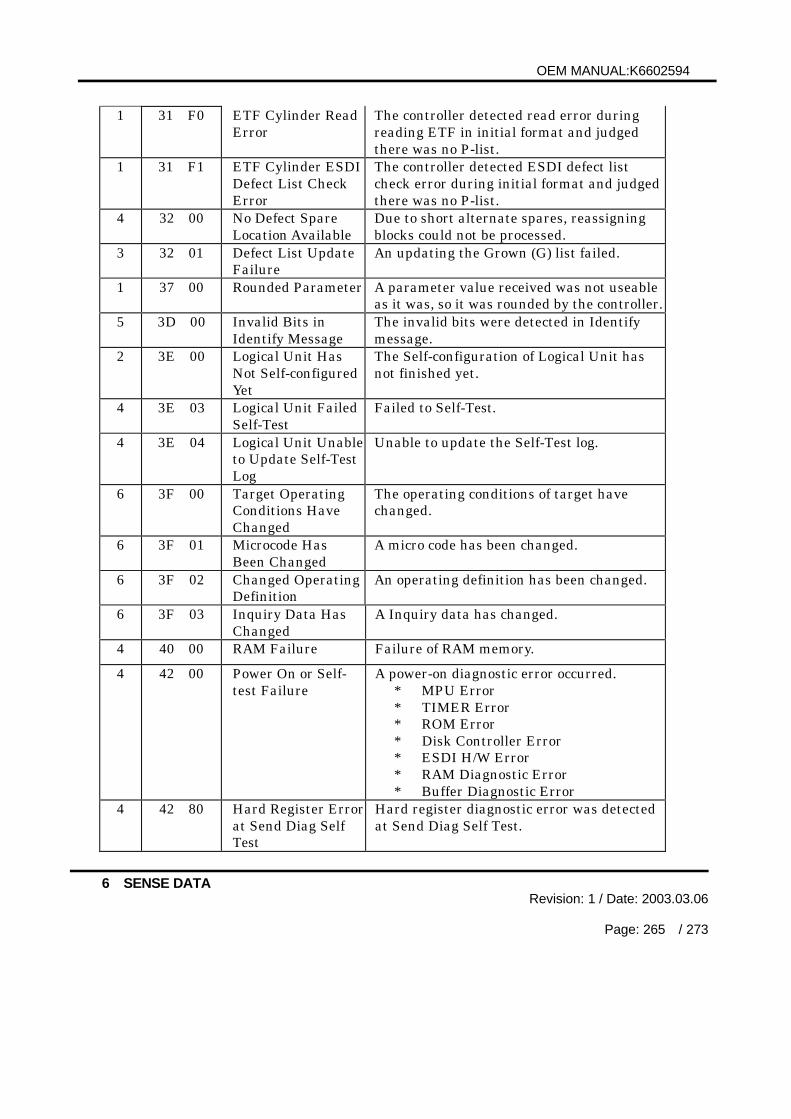
OEM MANUAL:K6602594
6 SENSE DATARevision: 1 / Date: 2003.03.06
Page: 265 / 273
1 31 F0 ETF Cylinder ReadError
The controller detected read error duringreading ETF in initial format and judgedthere was no P-list.
1 31 F1 ETF Cylinder ESDIDefect List CheckError
The controller detected ESDI defect listcheck error during initial format and judgedthere was no P-list.
4 32 00 No Defect SpareLocation Available
Due to short alternate spares, reassigningblocks could not be processed.
3 32 01 Defect List UpdateFailure
An updating the Grown (G) list failed.
1 37 00 Rounded Parameter A parameter value received was not useableas it was, so it was rounded by the controller.
5 3D 00 Invalid Bits inIdentify Message
The invalid bits were detected in Identifymessage.
2 3E 00 Logical Unit HasNot Self-configuredYet
The Self-configuration of Logical Unit hasnot finished yet.
4 3E 03 Logical Unit FailedSelf-Test
Failed to Self-Test.
4 3E 04 Logical Unit Unableto Update Self-TestLog
Unable to update the Self-Test log.
6 3F 00 Target OperatingConditions HaveChanged
The operating conditions of target havechanged.
6 3F 01 Microcode HasBeen Changed
A micro code has been changed.
6 3F 02 Changed OperatingDefinition
An operating definition has been changed.
6 3F 03 Inquiry Data HasChanged
A Inquiry data has changed.
4 40 00 RAM Failure Failure of RAM memory.
4 42 00 Power On or Self-test Failure
A power-on diagnostic error occurred.* MPU Error* TIMER Error* ROM Error* Disk Controller Error* ESDI H/W Error* RAM Diagnostic Error* Buffer Diagnostic Error
4 42 80 Hard Register Errorat Send Diag SelfTest
Hard register diagnostic error was detectedat Send Diag Self Test.

OEM MANUAL:K6602594
6 SENSE DATARevision: 1 / Date: 2003.03.06
Page: 266 / 273
B 43 00 Message Error The message was rejected and the operationcould not be continued.
4 44 00 Internal TargetError
A hardware or firmware error was detectedin the controller during a commandexecution.
4 44 01 Cache AllocationFailure
Failed to execute a cache allocation
4 44 80 Incomplete CacheOut
Write data from cache to disk has notcompleted because of an error.
4 44 81 Unable to Write dueto PIN
Unable to write data due to PIN(afterIncomplete Cache Out occurred).
4 44 83 Un-reported ErrorThreshold Exceeded
The number of un-reported errors exceededthreshold.
4 44 90 Management DataRead Error
Failed to read Management Data in thesystem area.
4 44 92 Directory DataRead Error
Failed to read Directory Data in the systemarea.
4 44 93 Directory DataWrite Error
Failed to write Directory Data in the systemarea.
4 44 94 Unable to AccessSystem Area
Failed to read/write the system area.
4 44 95 Unable to WriteSystem Area
Unable to wtite the system area due to a lackof valid track.
4 44 96 Unable to WriteManagement Data
Unable to wtite the system area due to a lackof valid Management Data.
4 44 97 Master Data ReadError
Failed to read Master Data in the systemarea.
4 44 98 Can’t Multi TrackWrite RemainTrackless
Unable to write to Multi Track in the systemarea due to remain trackless.
4 44 99 Multi Track WriteError
Failed to write to the whole Multi Track inthe system area.
4 44 9A Multi Track R/WParameter Error
Parameter error was detected in multi trackR/W.
4 44 9C Read CRC CheckError
A CRC check error occurred on reading fromthe system area.
4 44 9D Write CRC CheckError
A CRC check error occurred on write to thesystem area.
4 44 9E Master Data WriteError
Failed to write Master Data in the systemarea.
4 44 9F System Area AccessError
Failed to read/write the system area due todrive time out.
4 44 A0 Internal TargetError
The target sector was not found in reassignoperation.
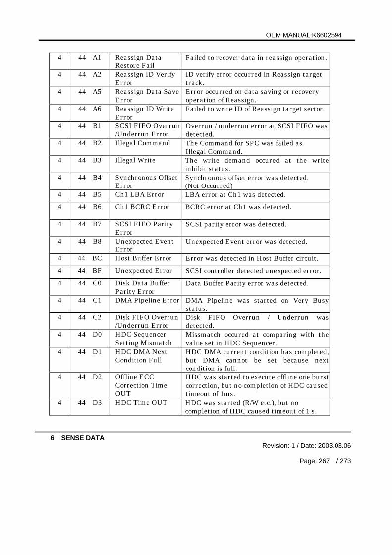
OEM MANUAL:K6602594
6 SENSE DATARevision: 1 / Date: 2003.03.06
Page: 267 / 273
4 44 A1 Reassign DataRestore Fail
Failed to recover data in reassign operation.
4 44 A2 Reassign ID VerifyError
ID verify error occurred in Reassign targettrack.
4 44 A5 Reassign Data SaveError
Error occurred on data saving or recoveryoperation of Reassign.
4 44 A6 Reassign ID WriteError
Failed to write ID of Reassign target sector.
4 44 B1 SCSI FIFO Overrun/Underrun Error
Overrun / underrun error at SCSI FIFO wasdetected.
4 44 B2 Illegal Command The Command for SPC was failed asIllegal Command.
4 44 B3 Illegal Write The write demand occured at the writeinhibit status.
4 44 B4 Synchronous OffsetError
Synchronous offset error was detected.(Not Occurred)
4 44 B5 Ch1 LBA Error LBA error at Ch1 was detected.
4 44 B6 Ch1 BCRC Error BCRC error at Ch1 was detected.
4 44 B7 SCSI FIFO ParityError
SCSI parity error was detected.
4 44 B8 Unexpected EventError
Unexpected Event error was detected.
4 44 BC Host Buffer Error Error was detected in Host Buffer circuit.
4 44 BF Unexpected Error SCSI controller detected unexpected error.
4 44 C0 Disk Data BufferParity Error
Data Buffer Parity error was detected.
4 44 C1 DMA Pipeline Error DMA Pipeline was started on Very Busystatus.
4 44 C2 Disk FIFO Overrun/Underrun Error
Disk FIFO Overrun / Underrun wasdetected.
4 44 D0 HDC SequencerSetting Mismatch
Missmatch occured at comparing with thevalue set in HDC Sequencer.
4 44 D1 HDC DMA NextCondition Full
HDC DMA current condition has completed,but DMA cannot be set because nextcondition is full.
4 44 D2 Offline ECCCorrection TimeOUT
HDC was started to execute offline one burstcorrection, but no completion of HDC causedtimeout of 1ms.
4 44 D3 HDC Time OUT HDC was started (R/W etc.), but nocompletion of HDC caused timeout of 1 s.

OEM MANUAL:K6602594
6 SENSE DATARevision: 1 / Date: 2003.03.06
Page: 268 / 273
4 44 D4 HDC Stop HDC stopped injuriously
4 44 D5 Wrap Error Wrap error was detected.
4 44 D6 Disk Port ParityError
Disk Port Parity Error was detected.
4 44 D7 Ch0 Check CodeError
LBA/CRC Check code error was detected inCh0.
4 44 D8 Write After ReadCheck Error
Write after read check error occurred.
4 44 DA DF Interrupt StatusResister Error
Error was detected in DF Interrupt StatusResister.
4 44 DB ECC status ResisterError
Error was detected in ECC Status Resister.
4 44 DC BC Interrupt StatusResister Error
Error was detected in BC Interrupt StatusResister.
4 44 DD Hardware Error atESDI StandardStatus
Hardware error was detected in standardstatus.
4 44 DF Novalid ErrorStatus For DriveATN
There ware no valid stasus for DriveAttention.
4 44 F1 Invalid LogicalCylinder Count
Invalid Logical Cylinder Number wasreported from drive control program.(exceed maximum Logical Cylinder Number)
4 44 F2 Head Health CheckError
Error was detected in Head Health Check.
4 44 F3 Program &Parameter DownLoad CompareError
A compare error was detected in microprogram & parameter downloading.
4 44 F4 Hardware Error atController Self Test
Hardware error was detected at thecontroller self test.
4 44 F8 Error in DriveMicrocomputer
Error was detected in Drive Microcomputerprogram overwriting
4 44 F9 Error in Flush ROM Error was detected in Flush ROMoverwriting.
4 44 FA Module Sum Errorin ROM Mode
SUM check error was detected in ROMoverwriting.
4 44 FE Error in S-RAMMarks DownloadUnable
Unable to download micro program for S-RAMerror.
4 44 FF Detected FirmwareError
A firmware error which should be reportedwithCheck Condition Status was detected.

OEM MANUAL:K6602594
6 SENSE DATARevision: 1 / Date: 2003.03.06
Page: 269 / 273
B 45 00 Select/ReselectFailed
A Select/Reselect time out was occurred.An invalid selection was detected.
B 47 00 SCSI Parity Error A parity error occurred on the SCSIinterface.
B 47 01 Data Phase CRCError Detected
A CRC error occurred in Data Phase.
B 47 03 Information UnitCRC Error Detected
A CRC error occurred in Information Unit.
B 48 00 Initiator DetectedError MessageReceived
An Initiator Detected Error message wasreceived from an initiator.
B 48 80 SCSI Phase RetryOut
A SCSI phase retry out was occurred.
B 49 00 Invalid MessageError
An invalid message was received.
B 4A 00 Command PhaseError
An error occurred in Command Phase.
B 4B 00 Data Phase Error An error occurred in Data Phase.4 4C 00 Logical Unit Failed
Self-configurationA loading of microcode or parameters failedduring controller initialization.
4 4C 80 Ram ConfigurationLoad Error
Failed to configuration load for raminitializing.
4 4C 81 Program RevisionCheck Error
Failed to download micro program forprogram revision check .
4 4C 82 Module Not Found Failed to download micro program forprogram size.
4 4C 83 Module Sum Error SUM check error was detected in programdown loading.
4 4C 84 Defect ParameterLoad Error
A loading of defect parameter failed duringcontroller initialization
B 4E 00 OverlappedCommandsAttempted
Both tagged command and untaggedcommand from the same initiator are issuedat a same time.- A tagged command which specifies thesame tag number is issued from the sameinitiator.- An untagged command is issued from thesame initiator which has issued anotheruntagged command.
5 55 04 InsufficientRegistrationResources
The reservation key registration failed.
1 5B 00 Log Exception The Log exception was detected.
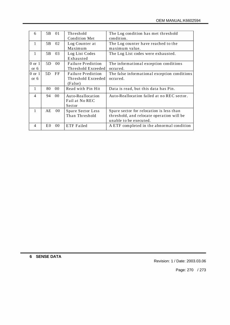
OEM MANUAL:K6602594
6 SENSE DATARevision: 1 / Date: 2003.03.06
Page: 270 / 273
6 5B 01 ThresholdCondition Met
The Log condition has met thresholdcondition.
1 5B 02 Log Counter atMaximum
The Log counter have reached to themaximum value.
1 5B 03 Log List CodesExhausted
The Log List codes were exhausted.
0 or 1or 6
5D 00 Failure PredictionThreshold Exceeded
The informational exception conditionsoccured.
0 or 1or 6
5D FF Failure PredictionThreshold Exceeded(False)
The false informational exception conditionsoccured.
1 80 00 Read with Pin Hit Data is read, but this data has Pin.
4 94 00 Auto-ReallocationFail at No RECSector
Auto-Reallocation failed at no REC sector.
1 AE 00 Spare Sector LessThan Threshold
Spare sector for relocation is less thanthreshold, and relocate operation will beunable to be executed.
4 E0 00 ETF Failed A ETF completed in the abnormal condition

OEM MANUAL:K6602594
6 SENSE DATARevision: 1 / Date: 2003.03.06
Page: 271 / 273
Table 6.4 Field Pointer
BitByte
7 6 5 4 3 2 1 0
15 SKSV C/D Reserved BPV Bit Pointer0 0
16 Field Pointer (MSB)
17 Field Pointer (LSB)
When the sense key is Illegal REQUEST and the SKSV bit is set to 1, theSense-Key Specific field (Byte 15-17) defines the contents as shown in Table 6.4.If the C/D (Command / Data) bit is set to 1, it indicates that the CDBcontains an invalid parameter. If the C/D bit is set to 0, it indicates thatthe transferred data during DATA OUT phase contain an invalid parameter.The BPV (Bit Pointer Valid) bit of 1 indicates that the Bit Pointer fieldcontents is determined. The BPV bit of 0 indicates that the Bit Pointer isundetermined.The Bit Pointer is effective when the BPV bit is set to 1 and indicates thebit position of an invalid parameter which is detected first.The Field Pointer indicates that the byte position of an invalid parameterwhich is detected first.
Table 6.5 Actual Retry Count
BitByte
7 6 5 4 3 2 1 0
15 SKSV Reserved0 0 0 0 0 0 0
16 Actual Retry Count (MSB)
17 Actual Retry Count (LSB)
When the sense key is RECOVERED ERROR, MEDIUM ERROR orHARDWARE ERROR and the SKSV bit is set to 1, the Sense-Key Specificfield defines the contents as shown in Table 6.5.The Actual Retry Count indicates the number of retries actually performed bythe controller. If the error is not regarded as a subject of recovery usingretries, the value of 0000H is indicated in the field.
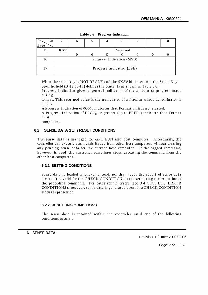
OEM MANUAL:K6602594
6 SENSE DATARevision: 1 / Date: 2003.03.06
Page: 272 / 273
Table 6.6 Progress Indication
BitByte
7 6 5 4 3 2 1 0
15 SKSV Reserved0 0 0 0 0 0 0
16 Progress Indication (MSB)
17 Progress Indication (LSB)
When the sense key is NOT READY and the SKSV bit is set to 1, the Sense-KeySpecific field (Byte 15-17) defines the contents as shown in Table 6.6.Progress Indication gives a general indication of the amount of progress madeduringformat. This returned value is the numerator of a fraction whose denominator is65536.A Progress Indication of 0000H indicates that Format Unit is not started.A Progress Indication of FFCCH or greater (up to FFFFH) indicates that FormatUnitcompleted.
6.2 SENSE DATA SET / RESET CONDITIONS
The sense data is managed for each LUN and host computer. Accordingly, thecontroller can execute commands issued from other host computers without clearingany pending sense data for the current host computer. If the tagged command,however, is used, the controller sometimes stops executing the command from theother host computers.
6.2.1 SETTING CONDITIONS
Sense data is loaded whenever a condition that needs the report of sense dataoccurs. It is valid for the CHECK CONDITION status set during the execution ofthe preceding command. For catastrophic errors (see 3.4 SCSI BUS ERRORCONDITIONS), however, sense data is generated even if no CHECK CONDITIONstatus is presented.
6.2.2 RESETTING CONDITIONS
The sense data is retained within the controller until one of the followingconditions occurs :

OEM MANUAL:K6602594
6 SENSE DATARevision: 1 / Date: 2003.03.06
Page: 273 / 273
- The sense data is transferred to the host computer by issuing a REQUESTSENSE command.
- A command other than the REQUEST SENSE command is received.- An Abort message is received.- An Abort Tag message is received.- An Clear Queue message is received.- A reset condition is generated (by a Bus Device Reset message or a reset or
power-on reset).