Hitachi Freedom Storage™ Lightning 9900™ V Series Sun®...
102
Hitachi Freedom Storage™ Lightning 9900™ V Series Sun ® Solaris™ Configuration Guide
-
Upload
duongxuyen -
Category
Documents
-
view
216 -
download
3
Transcript of Hitachi Freedom Storage™ Lightning 9900™ V Series Sun®...
Hitachi Freedom Storage™ Lightning 9900™ V Series
Sun® Solaris™ Configuration Guide


Hitachi Lightning 9900™ V Series Sun® Solaris™ Configuration Guide iii
© 2002 Hitachi Data Systems Corporation, ALL RIGHTS RESERVED
Notice: No part of this publication may be reproduced or transmitted in any form or by any means, electronic or mechanical, including photocopying and recording, or stored in a database or retrieval system for any purpose without the express written permission of Hitachi Data Systems Corporation (Hitachi Data Systems).
Hitachi Data Systems reserves the right to make changes to this document at any time without notice and assumes no responsibility for its use. Hitachi Data Systems products and services can only be ordered under the terms and conditions of Hitachi Data Systems’ applicable agreements. All of the features described in this document may not be currently available. Refer to the most recent product announcement or contact your local Hitachi Data Systems sales office for information on feature and product availability.
This document contains the most current information available at the time of publication. When new and/or revised information becomes available, this entire document will be updated and distributed to all registered users.
Trademarks
Hitachi Data Systems is a registered trademark and service mark of Hitachi, Ltd., and the Hitachi Data Systems design mark is a trademark and service mark of Hitachi, Ltd.
ExSA, Extended Serial Adapter, Hitachi Freedom Storage, and Lightning 9900 are trademarks of Hitachi Data Systems Corporation.
ESCON, FICON, and S/390 are registered trademarks of International Business Machines Corporation (IBM).
Emerald, EZ Fibre, and JNI are trademarks of JNI Corporation.
SPARC is a registered trademark of SPARC International, Inc. in the United States. SPARCstation, SPARCserver, and SPARCcenter are trademarks of SPARC International, Inc. and are licensed exclusively to Sun Microsystems, Inc.
Sun, Sun Microsystems, Solaris, and Ultra are registered trademarks or trademarks of Sun Microsystems, Inc.
VERITAS is a registered trademark of VERITAS Software Corp.
UNIX is a registered trademark of X/Open Company Limited in the United States and other countries and is licensed exclusively through X/Open Company Limited.
All other brand or product names are or may be trademarks or service marks of and are used to identify products or services of their respective owners.

iv Preface
Notice of Export Controls
Export of technical data contained in this document may require an export license from the United States government and/or the government of Japan. Please contact the Hitachi Data Systems Legal Department for any export compliance questions.
Document Revision Level
Revision Date Description
MK-92RD123-0 April 2002 Initial Release
Source Documents for this Revision
N/A
Changes in this Revision
Updated fibre-channel adapter information (section 2.1).
Added note on loop ID conflict (section 2.3.2).
Added items to acronym list.
Referenced Documents
Hitachi Lightning 9900™ V Series User and Reference Guide, MK-92RD100.
Hitachi Lightning 9900™ V Series Remote Console – Storage Navigator User’s Guide, MK-92RD101.
Hitachi Lightning 9900™ V Series LUN Manager User’s Guide, MK-92RD105.
Hitachi Lightning 9900™ V Series LUN Expansion (LUSE) and Virtual LVI/LUN User’s Guide, MK-92RD104.
Hitachi Lightning 9900™ V Series Hitachi RapidXchange User’s Guide, MK-91RD052.
Hitachi Freedom Storage™ Hitachi Dynamic Link Manager User’s Guide for Solaris™, MK-92DLM114.

Hitachi Lightning 9900™ V Series Sun® Solaris™ Configuration Guide v
Preface
The Hitachi Lightning 9900™ V Series Sun® Solaris™ Configuration Guide describes and provides instructions for configuring the devices on the Hitachi Lightning 9900™ V Series array subsystem for operation with the Sun® Solaris™ operating system. This configuration guide assumes that:
the user has a background in data processing and understands direct-access storage device subsystems and their basic functions,
the user is familiar with the Hitachi Lightning 9900™ V Series array subsystem,
the user is familiar with the Sun® Solaris™ operating system and the Sun® SPARCstation™, SPARCserver™, SPARCcenter™, and/or Ultra™ Series systems, and
the user is familiar with the UNIX® file system, system commands, and utilities.
Note: The term “9900 V” refers to the entire Hitachi Lightning 9900™ V Series subsystem family, unless otherwise noted. Please refer to the Hitachi Lightning 9900™ V Series User and Reference Guide (MK-92RD100) for further information on the 9900 V subsystems.
For further information on the Sun® Solaris™ operating system, please consult the Sun® Solaris™ online help and/or user documentation, or contact Sun® technical support.
Microcode Level
This document revision applies to 9900 V microcode versions 21-01-xx and higher.
COMMENTS Please send us your comments on this document: [email protected].
Make sure to include the document title, number, and revision. Please refer to specific page(s) and paragraph(s) whenever possible.
(All comments become the property of Hitachi Data Systems Corporation.)
Thank you!

vi Preface

Hitachi Lightning 9900™ V Series Sun® Solaris™ Configuration Guide vii
Contents
Chapter 1 Overview of 9900 V Solaris™ Configuration
1.1 9900 V Solaris™ Configuration ..................................................................1 1.2 Hitachi Lightning 9900™ V Series Subsystem .................................................1 1.3 Device Types and Configuration Procedures..................................................2
Chapter 2 Preparing for New Device Configuration
2.1 Configuration Requirements ....................................................................7 2.2 Installing the 9900 V Subsystem ................................................................8 2.3 Preparing to Connect the 9900 V Subsystem .................................................9
2.3.1 Setting the Host Mode for the 9900 V Ports .........................................9 2.3.2 Configuring the 9900 V Fibre-Channel Ports....................................... 10
2.4 Verifying the Host Fibre-Channel Adapter Installation ................................... 12 2.5 Configuring the Host Fibre-Channel Adapter(s)............................................ 13
2.5.1 Sample Instructions for Jaycor FC Adapters....................................... 13 2.5.1.1 Setting the FCA* File ...................................................... 13 2.5.1.2 Editing the /kernel/drv/fca-pci.conf file.............................. 14 2.5.1.3 Connecting to Fibre Switch............................................... 17 2.5.1.4 Connecting to FC-AL....................................................... 17
2.5.2 Sample Instructions for JNI™ 1-Gb Emerald™-Based FC Adapters.............. 19 2.5.2.1 Verifying the FC Emerald™- Based Adapter and Utility .............. 19 2.5.2.2 Configuring the JNI FC Emerald™-Based Adapter ..................... 21 2.5.2.3 Connecting to Fabric Switch ............................................. 24 2.5.2.4 Example of jnic.conf File and Parameter Information............... 26
2.5.3 Sample Instructions for JNI™ 2-Gb Emerald™-Based FC Adapters .............. 31 2.5.3.1 Verifying the FC 2-Gb Emerald™- Based Adapter and Utility ....... 31 2.5.3.2 Configuring the JNI FC Emerald™- Based Adapter .................... 33 2.5.3.3 Connecting to Fabric Switch ............................................. 36 2.5.3.4 Example of jnic146x.conf File and Parameter Information ......... 38
2.6 Setting the Disk and Device Parameters .................................................... 44 2.7 Connecting the 9900 V Subsystem to the Sun® System ................................... 46
Chapter 3 Configuring the 9900 V Devices
3.1 Setting and Recognizing the LUs ............................................................. 48 3.2 Verifying Recognition of New Devices ....................................................... 51 3.3 Partitioning and Labeling the New Devices................................................. 52 3.4 Creating and Mounting the File Systems .................................................... 65
3.4.1 Creating the File Systems ............................................................ 65 3.4.2 Creating and Verifying the Mount Directories..................................... 66 3.4.3 Mounting and Verifying the File Systems .......................................... 66 3.4.4 Setting and Verifying the Auto-Mount Parameters ............................... 68

viii Contents
Chapter 4 Failover and SNMP Configuration
4.1 Host Failover .....................................................................................69 4.2 Path Failover .....................................................................................69 4.3 SNMP Remote Subsystem Management.......................................................70
Chapter 5 Troubleshooting
5.1 Troubleshooting .................................................................................71 5.2 Verbose Mode ....................................................................................72 5.3 Calling the Hitachi Data Systems Support Center ..........................................74
Appendix A Pinned Track Recovery ..............................................................................75
Appendix B Fibre Port Addressing................................................................................77
Appendix C Online Device Installation ...........................................................................79
Appendix D Configuring the Boot Disk on the 9900 V
D.1 Introduction ......................................................................................81 D.2 Partition Check ..................................................................................82 D.3 File System Creation ............................................................................83 D.4 Boot Block Installation..........................................................................83 D.5 Required Files Directories Copy...............................................................84 D.6 OpenBoot Modification .........................................................................86
Appendix E Reference Information for VERITAS® VxVM DMP
E.1 Restrictions.......................................................................................89 E.2 Jaycor Driver Configuration Setting ..........................................................89
Acronyms and Abbreviations .......................................................................................91

Hitachi Lightning 9900™ V Series Sun® Solaris™ Configuration Guide ix
List of Figures
Figure 2.1 Setting the Host Mode .....................................................................9 Figure 2.2 Setting the Fibre-Channel Port Parameters .......................................... 11 Figure 2.3 Displaying the Fibre Device Information (Jaycor FC-1063)......................... 12 Figure 2.4 Example of set timeout_reset_enable = 1 ........................................... 15 Figure 2.5 Example of set recovery_attempts = 5 ............................................... 15 Figure 2.6 Example of failover = 180 ............................................................... 15 Figure 2.7 Example of ip_disable=1................................................................. 15 Figure 2.8 Example of def_wwn_binding, def_wwpn_binding and def_wwnn_binding..... 15 Figure 2.9 Example of def_port_binding ........................................................... 16 Figure 2.10 Example of fca_verbose=1 .............................................................. 16 Figure 2.11 Example of watchdog_reset_count=1 and watchdog_reset_wakeups=10........ 16 Figure 2.12 Example of /kernel/drv/fca-pci.conf ................................................. 18 Figure 2.13 Example of SCSI ID Change.............................................................. 18 Figure 2.14 Displaying the Fibre Device Information (Jaycor FCE-6410 shown)............... 20 Figure 2.15 Example of JNI™ Driver Parameters ................................................... 22 Figure 2.16 Example of JNI™ LUN-Level Zoning .................................................... 23 Figure 2.17 Example of JNI™ Driver Parameters for Fabric Switch.............................. 25 Figure 2.18 Example of jnic.conf File............................................................ 26-30 Figure 2.19 Displaying the Fibre Device Information (Jaycor FCE-1473 shown)............... 32 Figure 2.20 Example of JNI™ Driver Parameters ................................................... 34 Figure 2.21 Example of JNI™ LUN-Level Zoning .................................................... 35 Figure 2.22 Example of JNI™ Driver Parameters for Fabric Switch.............................. 37 Figure 2.23 Example of a jnic146x.conf File.................................................... 38-43 Figure 2.24 Setting the I/O TOV ...................................................................... 45 Figure 2.25 Setting the Max Throttle (Queue Depth).............................................. 45
Figure 3.1 Setting and Recognizing LUs ............................................................ 49 Figure 3.2 Fibre Device Recognition ................................................................ 50 Figure 3.3 Verifying New Devices ................................................................... 51 Figure 3.4 Verifying New Devices for Disk Partitioning .......................................... 54 Figure 3.5 Defining and Setting the Disk Type .................................................... 55 Figure 3.6 Setting the Partition(s) .............................................................. 56-57 Figure 3.7 Labeling the Disk and Verifying the Disk Label ...................................... 58 Figure 3.8 Creating the File Systems ............................................................... 65 Figure 3.9 Creating and Verifying a Mount Directory ............................................ 66 Figure 3.10 Mounting and Verifying the File System............................................... 67 Figure 3.11 Setting the Auto-Mount Parameters ................................................... 68
Figure 4.1 9900 V SNMP Environment............................................................... 70
Figure 5.1 Turning on Verbose Flag................................................................. 72 Figure 5.2 Examples of Error Messages......................................................... 72-73
Figure A.1 Recovering a Pinned Track .............................................................. 76
Figure D.1 OS System Drive Partitions .............................................................. 82 Figure D.2 Creating a New File System............................................................. 83

x Contents
Figure D.3 Installing a Boot Block....................................................................83 Figure D.4 Installing a Boot Block....................................................................83 Figure D.5 Creating the Directory Structure for Root Directory ................................84 Figure D.6 Updating the vfstab File .................................................................84 Figure D.7 Creating the Directory Structure for /usr Partition .................................85
List of Tables
Table 1.1 9900 V Device Specifications ...........................................................3-4 Table 1.2 Volume Usage for Device Categories.................................................... 4
Table 2.1 Fibre Parameter Settings for the 9900 V ..............................................10 Table 2.2 Available AL-PA Values ...................................................................11 Table 2.3 Max Throttle (Queue Depth) Requirements for the 9900 V Devices...............44
Table 3.1 9900 V Device Geometry Parameters ..................................................59 Table 3.2 Geometry Parameters for OPEN-3*n LUSE Devices...................................60 Table 3.3 Geometry Parameters for OPEN-9*n LUSE Devices...................................61 Table 3.4 Geometry Parameters for OPEN-E*n LUSE Devices...................................62 Table 3.5 Geometry Parameters for OPEN-L*n LUSE Devices...................................63 Table 3.6 Geometry Parameters for OPEN-x*n VLL-LUSE Devices (Example) ................64 Table 3.7 Auto-Mount Parameters ..................................................................68
Table 5.1 Troubleshooting ...........................................................................71
Table B.1 Fibre Port Addressing.................................................................77-78

Hitachi Lightning 9900™ V Series Sun® Solaris™ Configuration Guide 1
Chapter 1 Overview of 9900 V Solaris™ Configuration
1.1 9900 V Solaris™ Configuration
This document describes the requirements and procedures for connecting the Hitachi Lightning 9900™ V Series (9900 V) subsystem to a Sun® Solaris™ system and configuring the new 9900 V devices for operation with the Solaris™ operating system. The Hitachi Data Systems representative performs the physical installation of the 9900 V subsystem. The user prepares for 9900 V subsystem installation and configures the new 9900 V devices with assistance as needed from the Hitachi Data Systems representative.
Configuration of the Lightning 9900™ V Series disk devices for Solaris™ operations includes:
Setting and recognizing the LUs (see section 3.1),
Verifying new device recognition (see section 3.2),
Partitioning and labeling the disk (see section 3.3), and
Creating and mounting the file system (see section 3.4).
Note on the term “SCSI disk”: The 9900 V logical devices are defined to the host as SCSI disk devices, even though the interface is fibre-channel.
1.2 Hitachi Lightning 9900™ V Series Subsystem
The Hitachi Lightning 9900™ V Series RAID subsystem supports concurrent attachment to multiple UNIX®-based and PC-server platforms. Please contact your Hitachi Data Systems account team for the latest information on platform support. The 9900 V subsystem provides continuous data availability, high-speed response, scaleable connectivity, and expandable capacity for PC server and open-system storage. The 9900 V subsystem can operate with multihost applications and host clusters, and is designed to handle very large databases as well as data warehousing and data mining applications that store and retrieve terabytes of data.
The Hitachi Lightning 9900™ V Series subsystem can be configured with fibre-channel, FICON™, and/or Extended Serial Adapter™ (ExSA™) ports (compatible with ESCON® protocol) to provide connectivity with S/390® mainframe hosts as well as open-system hosts. For further information on the 9900 V subsystem, please refer to the Hitachi Freedom Storage™ Lightning 9900™ V Series User and Reference Guide (MK-92RD100), or contact your Hitachi Data Systems account team.

2 Chapter 1 Overview of 9900 VSolaris™ Configuration
1.3 Device Types and Configuration Procedures
The 9900 V subsystem allows the following types of logical devices (also called volumes) to be installed and configured for operation with the Sun® Solaris™ operating system. Table 1.1 lists the device specifications for the 9900 V devices. Table 1.2 shows the volume usage (i.e., file system or raw device) for the 9900 V devices.
OPEN-x Devices. The OPEN-x logical units (LUs) (e.g., OPEN-3, OPEN-9) are disk devices of predefined sizes. The 9900 V subsystem currently supports OPEN-3, OPEN-9, OPEN-E, and OPEN-L devices. Please contact your Hitachi Data Systems account team for the latest information on supported LU types.
LUSE Devices (OPEN-x*n). The LUSE devices are combined LUs which can be from 2 to 36 times larger than standard OPEN-x LUs. The LUN Expansion (LUSE) Remote Console software enables you to configure these custom-size devices. LUSE devices are designated as OPEN-x*n, where x is the LU type (e.g., OPEN-9*n) and 2< n < 36. For example, a LUSE device created from ten OPEN-3 LUs would be designated as an OPEN-3*10 disk device. This capability enables the host to combine logical devices and access the data stored on the 9900 V subsystem using fewer LU numbers. For further information on the LUSE feature, please refer to the Hitachi Lightning 9900™ V Series LUN Expansion and Virtual LVI/LUN User’s Guide (MK-92RD104).
VLL Devices (OPEN-x VLL). The VLL devices are custom-size LUs which are smaller than standard OPEN-x LUs. The Virtual LVI/LUN Remote Console software enables you to configure VLL devices by “slicing up” a single LU into several smaller LUs. You can choose the device size that best fits your application needs to improve your host access to frequently used files. For further information on the Virtual LVI/LUN feature, please refer to the Hitachi Lightning 9900™ V Series LUN Expansion (LUSE) and Virtual LVI/LUN User’s Guide (MK-92RD104). Note: The product name for the OPEN-x VLL devices is OPEN-x-CVS (CVS stands for custom volume size).
VLL LUSE Devices (OPEN-x*n VLL). The VLL LUSE devices combine Virtual LVI/LUN devices (instead of standard OPEN-x LUs) into LUSE devices. The Virtual LVI/LUN feature is used to create custom-size devices, and then the LUSE feature is used to combine (concatenate) these VLL devices. The user can combine from 2 to 36 VLL devices into one VLL LUSE device. For example, an OPEN-3 LUSE volume created from ten OPEN-3 VLL volumes would be designated as an OPEN-3*10 VLL device (product name OPEN-3*10-CVS).
Configuration of the 9900 V disk devices for Solaris™ operations includes:
Setting and recognizing the LUs (see section 3.1),
Verifying new device recognition (see section 3.2),
Partitioning and labeling the disk (see section 3.3), and
Creating and mounting the file system (see section 3.4).

Hitachi Lightning 9900™ V Series Sun® Solaris™ Configuration Guide 3
HRX Devices (3390-3A/B/C, OPEN-x-HRXoto). The Hitachi RapidXchange (HRX) feature of the 9900 V subsystem enables user data to be shared across S/390®, UNIX®, and PC server platforms using special multiplatform volumes. The VLL feature can also be applied to HRX devices for maximum flexibility in volume size. For further information on HRX, please refer to the Hitachi RapidXchange User’s Guide (MK-91RD052), or contact your Hitachi Data Systems account team.
The HRX devices are not SCSI disk devices. The HRX devices must be installed and accessed as raw devices. UNIX®/PC server hosts must use HRX to access the HRX devices as raw devices (no file system, no mount operation).
Note: The 3390-3B devices are write-protected from UNIX®/PC server access. The 9900 V subsystem will reject all UNIX®/PC server write operations (including fibre-channel adapters) for the 3390-3B devices.
WARNING: The multiplatform devices are not write-protected for UNIX®/PC server access. Do not execute any write operation by the fibre-channel adapters on these devices. Do not create a partition or file system on these devices. This will overwrite any data on the HRX device and also prevent the HRX software from accessing the device.
Configuration of the 9900 V HRX devices for operation with Sun® Solaris™ includes:
Setting and recognizing the LUs (see section 3.1),
Verifying new device recognition (see section 3.2), and
Partitioning and labeling the disk (see section 3.3).
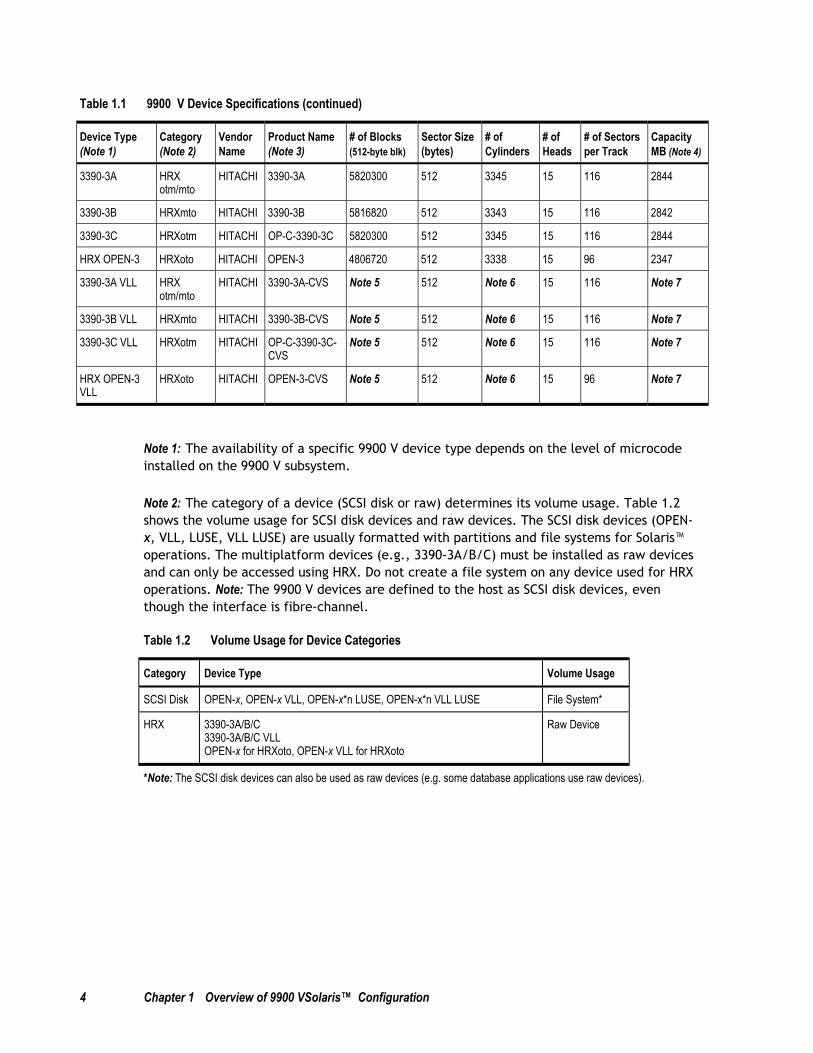
Table 1.1 9900 V Device Specifications (continues on the next page)
Device Type (Note 1)
Category (Note 2)
Vendor Name
Product Name (Note 3)
# of Blocks (512-byte blk)
Sector Size (bytes)
# of Cylinders
# of Heads
# of Sectors per Track
Capacity MB (Note 4)
OPEN-3 SCSI disk HITACHI OPEN-3 4806720 512 3338 15 96 2347
OPEN-9 SCSI disk HITACHI OPEN-9 14423040 512 10016 15 96 7042
OPEN-E SCSI disk HITACHI OPEN-E 28452960 512 19759 15 96 13893
OPEN-L SCSI disk HITACHI OPEN-L 71192160 512 49439 15 96 34761
OPEN-3*n SCSI disk HITACHI OPEN-3*n 4806720*n 512 3338*n 15 96 2347*n
OPEN-9*n SCSI disk HITACHI OPEN-9*n 14423040*n 512 10016*n 15 96 7042*n
OPEN-E*n SCSI disk HITACHI OPEN-E*n 28452960*n 512 19759*n 15 96 13893*n
OPEN-L*n SCSI disk HITACHI OPEN-L*n 71192160*n 512 49439*n 15 96 34761*n
OPEN-3 VLL SCSI disk HITACHI OPEN-3-CVS Note 5 512 Note 6 15 96 Note 7
OPEN-9 VLL SCSI disk HITACHI OPEN-9-CVS Note 5 512 Note 6 15 96 Note 7
OPEN-E VLL SCSI disk HITACHI OPEN-E-CVS Note 5 512 Note 6 15 96 Note 7
OPEN-3*n VLL SCSI disk HITACHI OPEN-3*n-CVS Note 5 512 Note 6 15 96 Note 7
OPEN-9*n VLL SCSI disk HITACHI OPEN-9*n-CVS Note 5 512 Note 6 15 96 Note 7
OPEN-E*n VLL SCSI disk HITACHI OPEN-E*n-CVS Note 5 512 Note 6 15 96 Note 7
4 Chapter 1 Overview of 9900 VSolaris™ Configuration
Table 1.1 9900 V Device Specifications (continued)
Device Type (Note 1)
Category (Note 2)
Vendor Name
Product Name (Note 3)
# of Blocks (512-byte blk)
Sector Size (bytes)
# of Cylinders
# of Heads
# of Sectors per Track
Capacity MB (Note 4)
3390-3A HRX otm/mto
HITACHI 3390-3A 5820300 512 3345 15 116 2844
3390-3B HRXmto HITACHI 3390-3B 5816820 512 3343 15 116 2842
3390-3C HRXotm HITACHI OP-C-3390-3C 5820300 512 3345 15 116 2844
HRX OPEN-3 HRXoto HITACHI OPEN-3 4806720 512 3338 15 96 2347
3390-3A VLL HRX otm/mto
HITACHI 3390-3A-CVS Note 5 512 Note 6 15 116 Note 7
3390-3B VLL HRXmto HITACHI 3390-3B-CVS Note 5 512 Note 6 15 116 Note 7
3390-3C VLL HRXotm HITACHI OP-C-3390-3C- CVS
Note 5 512 Note 6 15 116 Note 7
HRX OPEN-3 VLL
HRXoto HITACHI OPEN-3-CVS Note 5 512 Note 6 15 96 Note 7
Note 1: The availability of a specific 9900 V device type depends on the level of microcode installed on the 9900 V subsystem.
Note 2: The category of a device (SCSI disk or raw) determines its volume usage. Table 1.2 shows the volume usage for SCSI disk devices and raw devices. The SCSI disk devices (OPEN-x, VLL, LUSE, VLL LUSE) are usually formatted with partitions and file systems for Solaris™ operations. The multiplatform devices (e.g., 3390-3A/B/C) must be installed as raw devices and can only be accessed using HRX. Do not create a file system on any device used for HRX operations. Note: The 9900 V devices are defined to the host as SCSI disk devices, even though the interface is fibre-channel.
Table 1.2 Volume Usage for Device Categories
Category Device Type Volume Usage
SCSI Disk OPEN-x, OPEN-x VLL, OPEN-x*n LUSE, OPEN-x*n VLL LUSE File System*
HRX 3390-3A/B/C 3390-3A/B/C VLL OPEN-x for HRXoto, OPEN-x VLL for HRXoto
Raw Device
*Note: The SCSI disk devices can also be used as raw devices (e.g. some database applications use raw devices).

Hitachi Lightning 9900™ V Series Sun® Solaris™ Configuration Guide 5
Note 3: The 9900 V command device (used for Hitachi Command Control Interface operations) is distinguished by -CM on the product name (e.g., OPEN-3-CM, OPEN-3-CVS-CM). The product name for OPEN-x VLL devices is OPEN-x CVS (CVS = custom volume size).
Note 4: The device capacity can sometimes be changed by the BIOS or host adapter board. Also, different capacities may be due to variations such as 1 MB = 10002 or 10242 bytes.
Note 5: The number of blocks for a VLL volume is calculated as follows: # of blocks = (# of data cylinders) × (# of heads) × (# of sectors per track)
Example: For an OPEN-3 VLL volume with capacity = 37 MB: # of blocks = (53 cylinders–see Note 6) × (15 heads) × (96 sectors per track) = 76320
Note 6: The number of data cylinders for a VLL volume is calculated as follows (↑…↑ means that the value should be rounded up to the next integer):
The number of data cylinders for an OPEN-x VLL volume = # of cylinders = ↑ (capacity (MB) specified by user) × 1024/720 ↑ Example: For an OPEN-3 VLL volume with capacity = 37 MB: # of cylinders = ↑37 × 1024/720↑ = ↑52.62↑ (rounded up to next integer) = 53 cylinders
The number of data cylinders for a VLL LUSE volume = # of cylinders = ↑ (capacity (MB) specified by user) × 1024/720 ↑ × n Example: For an OPEN-3 VLL LUSE volume with capacity = 37 MB and n = 4 # of cylinders = ↑37 × 1024/720↑ × 4 = ↑52.62↑× 4 = 53 × 4 = 212
The number of data cylinders for a 3390-3A/C VLL volume = # of cylinders = (number of cylinders specified by user) + 9
The number of data cylinders for a 3390-3B VLL volume = # of cylinders = (number of cylinders specified by user) + 7
Note 7: The size of an OPEN-x VLL volume is specified by capacity in MB, not by number of cylinders. The user specifies the volume size using the 9900 V Virtual LVI/LUN software.
Note that OPEN-L cannot be used for VLL volumes.

6 Chapter 1 Overview of 9900 VSolaris™ Configuration

Hitachi Lightning 9900™ V Series Sun® Solaris™ Configuration Guide 7
Chapter 2 Preparing for New Device Configuration
2.1 Configuration Requirements
The requirements for Lightning 9900™ V Series Sun® Solaris™ configuration are:
Hitachi Lightning 9900™ V Series subsystem, all-open or multiplatform configuration.
– The 9900 V LUN Manager software is used to configure the fibre-channel (FC) ports. If the remote LUN Manager feature is not installed, please contact your Hitachi Data Systems account team for information on LUN and fibre-channel configuration services.
Note: The availability of 9900 V features and devices depends on the level of microcode installed on the 9900 V subsystem.
Sun® system: Sun® SPARCstation series, Sun® SPARCserver series, Sun® SPARCcenter series, or Sun® Ultra series.
Sun® Solaris™ OS, version 2.6, 7, or 8. Root login access to the Sun® system is required.
Important: Please contact Sun® to make sure that the most current OS patches are installed on the Sun® system(s).
Note: For the latest information on Solaris™ version support, please contact your Hitachi Data Systems account team.
Fibre-channel adapters. Make sure to install all utilities, tools, and drivers that come with the adapter(s). For information on driver requirements for the adapters, please refer to the user documentation for the adapter or contact the vendor.
– The 9900 V subsystem supports: 2 Gbps fibre-channel interface, including shortwave non-OFC (open fibre control) optical interface and multimode optical cables with LC connectors; and 1 Gbps fibre-channel interface, including shortwave non-OFC optical interface and multimode optical cables with SC connectors. Do not connect any OFC-type fibre-channel interface to the 9900 V subsystem.
– For information on supported FC adapters (FCAs), optical cables, hubs, and fabric switches, please contact your Hitachi Data Systems account team or the Hitachi Data Systems Support Center (see section 5.3).

8 Chapter 2 Preparing for New Device Configuration
2.2 Installing the 9900 V Subsystem
The 9900 V subsystem comes with all hardware and cabling required for installation. Installation of the 9900 V subsystem involves the following activities:
1. Hardware installation. The Hitachi Data Systems representative performs hardware installation as specified in the 9900 V maintenance manual. Follow all precautions and procedures in the 9900 V maintenance manual. Check all specifications to ensure proper installation and configuration. Hardware installation includes:
– Assembling all hardware and cabling.
– Installing and formatting the logical devices (LDEVs) using the SVP. Make sure to get the desired LDEV configuration information from the user, including the desired number of OPEN-x, LUSE, VLL, VLL LUSE, and multiplatform (HRX) devices.
– Installing the fibre-channel adapters and cabling: The total fibre cable length attached to each fibre-channel adapter must not exceed 500 meters (1,640 feet). Do not connect any OFC-type connector to the 9900 V subsystem. Do not connect/disconnect fibre-channel cabling that is being actively used for I/O. This can cause the Solaris™ system to hang. Always confirm that the devices on the fibre cable are offline before connecting or disconnecting the fibre cable.
9900 V FC Port: The fibre topology parameters for each 9900 V fibre-channel port depend on the type of device to which the 9900 V port is connected. Determine the topology parameters supported by the device, and set your topology accordingly (see section 2.3.2). The type of 9900 V port is also important.
Note: The Hitachi Data Systems representative must use the 9900 V Maintenance Manual during all installation activities. Follow all precautions and procedures in the maintenance manual, and always check all specifications to ensure proper installation and configuration.
2. LUN Manager software installation. The user can perform this activity. You will use the LUN Manager software to configure the fibre-channel ports. For instructions on installing the LUN Manager Remote Console software, please refer to the Hitachi Lightning 9900™ V Series Remote Console – Storage Navigator User’s Guide (MK-92RD101) and the Hitachi Lightning 9900™ V Series LUN Manager User’s Guide (MK-92RD105).
Note: If the remote LUN Manager feature is not installed, please contact your Hitachi Data Systems account team for information on fibre-channel configuration services.

Hitachi Lightning 9900™ V Series Sun® Solaris™ Configuration Guide 9
2.3 Preparing to Connect the 9900 V Subsystem
Before the 9900 V subsystem is connected to your Solaris™ system, you must perform the following tasks:
Set the host mode for the 9900 V fibre-channel port(s) (see section 2.3.1),
Configure the 9900 V fibre-channel ports (see section 2.3.2),
Verify the host fibre-channel adapters (see section 2.4),
Configure the host fibre-channel adapters (see section 2.5), and
Set the disk and device parameters (see section 2.6).
You will use the LUN Manager Remote Console software to set the host modes for and configure the 9900 V fibre ports. For instructions on using the LUN Manager software, please refer to the Hitachi Lightning 9900™ V Series LUN Manager User’s Guide (MK-92RD105).
Note: If the remote LUN Manager feature is not installed, please contact your Hitachi Data Systems account team for information on fibre-channel configuration services.
After completing these steps, you will shut down the Solaris™ system, connect the 9900 V subsystem, and then restart the Solaris™ system (see section 2.7).
2.3.1 Setting the Host Mode for the 9900 V Ports
The 9900 V ports have special modes which must be set for the connected operating system. Use the LUN Manager Remote Console software to set the host mode for each port (see Figure 2.1). The required host mode setting for 9900 V Solaris™ operations is 09.
Figure 2.1 Setting the Host Mode

10 Chapter 2 Preparing for New Device Configuration
2.3.2 Configuring the 9900 V Fibre-Channel Ports
You need to configure the 9900 V FC ports to define the fibre parameters (see Table 2.1, Figure 2.2, and Table 2.2). You will use the LUN Manager Remote Console software to configure the 9900 V FC ports. For instructions on using the LUN Manager software, please refer to the Hitachi Lightning 9900™ V Series LUN Manager User’s Guide (MK-92RD105).
Note: The 9900 V subsystem supports up to 256 LUs per fibre-channel port.
Fibre topology. Figure 2.2 shows the LUN Manager panel used to define the port parameters, and Table 2.1explains the settings on this panel. You will select the appropriate settings for each 9900 V FC port based on the device to which the port is connected. Determine the topology parameters supported by the device, and set your topology accordingly. The type of 9900 V port is also important. Note: If you plan to connect different types of servers to the 9900 V via the same fabric switch, you must use the zoning function of the fabric switch.
Port address. In fabric environments, the port addresses are assigned automatically by fabric switch port number and are not controlled by the 9900 V port settings. In arbitrated loop environments, the port addresses are set by entering an AL-PA (arbitrated-loop physical address, or loop ID). Table 2.2 shows the available 9900 V AL-PA values ranging from 01 to EF. Fibre-channel protocol uses the AL-PAs to communicate on the fibre-channel link, but the software driver of the platform host adapter translates the AL-PA value assigned to the 9900 V port to a SCSI TID. See Appendix B for a description of the AL-PA-to-TID translation.
Note on loop ID conflict: The Solaris™ system assigns port addresses from lowest (01) to highest (EF). To avoid loop ID conflict, assign the port addresses from highest to lowest (i.e., starting at EF). The AL-PAs should be unique for each device on the loop to avoid conflicts. Do not use more than one port address with the same TID in same loop (e.g., addresses EF and CD both have TID 0, refer to Appendix B for the TID-to-AL-PA mapping).
Table 2.1 Fibre Parameter Settings for the 9900 V
Fabric Connection Provides:
ON FC-AL FL-port (fabric port)
ON Point-to-Point F-port (fabric port)
OFF FC-AL NL-port (private arbitrated loop)
OFF Point-to-Point Not supported
Note: Please contact Hitachi Data Systems for detailed information about port topology configurations supported by each host bus adapter/switch combination. Not all types of switches support F-port connection.

Hitachi Lightning 9900™ V Series Sun® Solaris™ Configuration Guide 11
Figure 2.2 Setting the Fibre-Channel Port Parameters
Table 2.2 Available AL-PA Values
EF CD B2 98 72 55 3A 25
E8 CC B1 97 71 54 39 23
E4 CB AE 90 6E 53 36 1F
E2 CA AD 8F 6D 52 35 1E
E1 C9 AC 88 6C 51 34 1D
E0 C7 AB 84 6B 4E 33 1B
DC C6 AA 82 6A 4D 32 18
DA C5 A9 81 69 4C 31 17
D9 C3 A7 80 67 4B 2E 10
D6 BC A6 7C 66 4A 2D 0F
D5 BA A5 7A 65 49 2C 08
D4 B9 A3 79 63 47 2B 04
D3 B6 9F 76 5C 46 2A 02
D2 B5 9E 75 5A 45 29 01
D1 B4 9D 74 59 43 27
CE B3 9B 73 56 3C 26

12 Chapter 2 Preparing for New Device Configuration
2.4 Verifying the Host Fibre-Channel Adapter Installation
Before configuring the FC adapter(s), you must verify proper FC adapter installation. To ensure that the host FC adapter configuration is correct, you will verify recognition of the FCA and the FCA driver.
To verify the fibre-channel host configuration:
1. Log in to the Sun® system as root, and make sure that all existing devices are powered on and properly connected to the Sun® system.
2. Display the host configuration using the dmesg command (see Figure 2.3). The fibre information (underlined in the following example) includes the recognition of the fibre channel adapter, SCSI bus characteristics, world wide name, and FCA driver. Make sure that the host recognizes these four classes. If this information is not displayed or if error messages are displayed, the host environment may not be configured properly.
# dmesg
Nov 9 23:14ems, Inc.mem = 65536K (0x4000000)avail mem = 60129280Ethernet address = 8:0:20:92:32:48root nexus = Sun Ultra 1 SBus (UltraSPARC 167MHz)sbus0 at root: UPA 0x1f 0x0 ...espdma0 at sbus0: SBus0 slot 0xe offset 0x8400000esp0: esp-options=0x46esp0 at espdma0: SBus0 slot 0xe offset 0x8800000 Onboard device sparc9 ipl 4sd0 at esp0: target 0 lun 0sd0 is /sbus@1f,0/espdma@e,8400000/esp@e,8800000/sd@0,0
<SUN2.1G cyl 2733 alt 2 hd 19 sec 80>sd6 at esp0: target 6 lun 0sd6 is /sbus@1f,0/espdma@e,8400000/esp@e,8800000/sd@6,0fca0: JNI Fibre Channel Adapter (1062 MB/sec), model FC Verify thatfca0: SBus 1: IRQ 4: FCODE Version 11.0.9 [1a6384]: SCSI ID 125: AL_PA 01 these itemsfca0: Fibre Channel WWN: 100000e0690000d5 are listed.fca0: FCA Driver Version 2.2.HIT.03, Oct 09, 1999 Solaris 2.5, 2.6fca0: All Rights Reserved.fca0: < Total IOPB space used: 1125824 bytes >fca0: < Total DMA space used: 565277 bytes >root on /sbus@1f,0/espdma@e,8400000/esp@e,8800000/sd@0,0:a fstype ufszs0 at sbus0: SBus0 slot 0xf offset 0x1100000 Onboard device sparc9 ipl 12zs0 is /sbus@1f,0/zs@f,1100000zs1 at sbus0: SBus0 slot 0xf offset 0x1000000 Onboard device sparc9 ipl 12zs1 is /sbus@1f,0/zs@f,1000000keyboard is </sbus@1f,0/zs@f,1000000> major <29> minor <2>mouse is </sbus@1f,0/zs@f,1000000:b> major <29> minor <3>stdin is </sbus@1f,0/zs@f,1000000> major <29> minor <2>• • • • • • • • • • • • • • • • • • • • • • • • • • • • • • • • •
Figure 2.3 Displaying the Fibre Device Information (Jaycor FC-1063)

Hitachi Lightning 9900™ V Series Sun® Solaris™ Configuration Guide 13
2.5 Configuring the Host Fibre-Channel Adapter(s)
After verifying the HBA installation, you are ready to configure the fibre-channel adapter(s) connected to the 9900 V. The host bus adapters (HBAs) have many configuration options. This section provides minimum requirements for configuring FC adapters for operation with the 9900 V subsystem. The following sample instructions apply to Jaycor and JNI™ FC adapters. For instructions on configuring other adapters, please refer to the user documentation for the adapter.
2.5.1 Sample Instructions for Jaycor FC Adapters
2.5.1.1 Setting the FCA* File
To configure the Jaycor FC-1063, FC64-1063, and FCI-1063 FCAs, set the fca*.conf file (in /kernel/drv/ directory), and add and/or confirm the following descriptions in the configuration file: timeout_reset_enable = 1 link_recovery_delay = 500 failover = 180; (see important note below for binding information) Note: The setting for link_recovery_delay is an industry standard. It is included here as information only. When using VERITAS® Volume Manager (VxVM) Dynamic Multi Pathing (DMP), set the following values: Recovery_attempts = 5 Failover = 60
When you use driver 2.5.8.HIT07.01 or later, add and/or confirm the value of the driver parameter: watchdog_reset_count = 1; watchdog_reset_wakeups = 24;(for 2.5.8.HIT.07.01 or later) When you use driver 2.5 with Solaris™ version 8, change the following parameter values: ip_disable = 1; (see important note below for binding information) fca_verbose = 1;
Configure these parameters as follows:
For 32-bit SBus adapters, configure the /kernel/drv/fca.conf file.
For 64-bit SBus adapters, configure the /kernel/drv/fca-pci.conf file.

14 Chapter 2 Preparing for New Device Configuration
Important Note: If you are performing WWN Persistent Binding, after the target is bound to the specified WWN, the target will then also be statically bound to only that port in the fabric due to the Def_port_binding statement. This setup will not allow you to move a device to a new port (e.g., due to a bad port on a switch), without requiring a reboot of the server. A system reboot can be necessary because of incorrect configuration.
If you are using persistent binding of any form, the static binding should match the persistent binding type. If you require static WWNN or WWPN binding, change the following definitions:
def_wwpn_binding = “xxxxxxxxxxxxxxxx”; Static Port binding---------------def_port_binding = “$xxxxxx”; def_wwnn_binding = “xxxxxxxxxxxxxxxx”;
def_wwpn_binding = “xxxxxxxxxxxxxxxx”; Static WWNN binding----------def_wwnn_binding = “$xxxxxxxxxxxxxxx”; def_port_binding = “xxxxxx”;
def_wwnn_binding =“xxxxxxxxxxxxxxxx”; Static WWPN binding----------def_wwpn_binding = “$xxxxxxxxxxxxxxx”; def_port_binding = “xxxxxx”;
2.5.1.2 Editing the /kernel/drv/fca-pci.conf file
To edit the /kernel/drv/fca-pci.conf file:
1. Log in as root.
2. Make a backup of fca-pci.conf: cp /kernel/drv/fca-pci.conf /kernel/drv/fca-pci.bk
3. Edit the fca-pci.conf file: vi /kernel/drv/fca-pci.conf
4. Enter: timeout_reset_enable = 1; (see Figure 2.4).
5. Enter: recovery_attempts = 5; (see Figure 2.5)
6. Enter: failover = 180; (see Figure 2.6)
7. Enter: ip_disable = 1; (This parameter is only for driver v2.5.) (see Figure 2.7)
8. Enter the appropriate binding parameters for your configuration: (see important note above for binding information) (see Figure 2.8))
9. Enter the appropriate binding parameters for your configuration (see Figure 2.8) (see important note above for binding information)
10. Enter (see Figure 2.9) (see important note above for binding information)
11. Enter: fca_verbose = 1; (see Figure 2.10)
Hitachi Lightning 9900™ V Series Sun® Solaris™ Configuration Guide 15
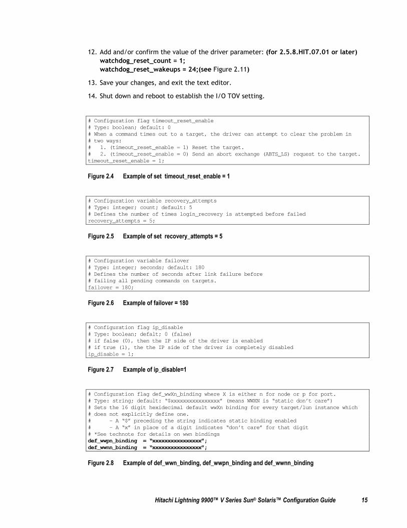
12. Add and/or confirm the value of the driver parameter: (for 2.5.8.HIT.07.01 or later) watchdog_reset_count = 1; watchdog_reset_wakeups = 24;(see Figure 2.11)
13. Save your changes, and exit the text editor.
14. Shut down and reboot to establish the I/O TOV setting.
# Configuration flag timeout_reset_enable# Type: boolean; default: 0# When a command times out to a target, the driver can attempt to clear the problem in# two ways:# 1. (timeout_reset_enable = 1) Reset the target.# 2. (timeout_reset_enable = 0) Send an abort exchange (ABTS_LS) request to the target.timeout_reset_enable = 1;
Figure 2.4 Example of set timeout_reset_enable = 1
# Configuration variable recovery_attempts# Type: integer; count; default: 5# Defines the number of times login_recovery is attempted before failedrecovery_attempts = 5;
Figure 2.5 Example of set recovery_attempts = 5
# Configuration variable failover# Type: integer; seconds; default: 180# Defines the number of seconds after link failure before# failing all pending commands on targets.failover = 180;
Figure 2.6 Example of failover = 180
# Configuration flag ip_disable# Type: boolean; defalt; 0 (false)# if false (0), then the IP side of the driver is enabled# if true (1), the the IP side of the driver is completely disabledip_disable = 1;
Figure 2.7 Example of ip_disable=1
# Configuration flag def_wwXn_binding where X is either n for node or p for port.# Type: string; default: “$xxxxxxxxxxxxxxxx” (means WWXN is “static don’t care”)# Sets the 16 digit hexidecimal default wwXn binding for every target/lun instance which# does not explicitly define one.# - A “$” preceding the string indicates static binding enabled# - A “x” in place of a digit indicates “don’t care” for that digit# *See technote for details on wwn bindingsdef_wwpn_binding = “xxxxxxxxxxxxxxxx”;def_wwnn_binding = “xxxxxxxxxxxxxxxx”;
Figure 2.8 Example of def_wwn_binding, def_wwpn_binding and def_wwnn_binding

16 Chapter 2 Preparing for New Device Configuration
# Configuration flag def_port_binding# Type: string; default: “xxxxxx” (means PORT is “non-static don’t care”)# Sets the 6 digit hexidecimal default port binding for every target/lun instance which# does not explicitly define one.# - A “$” preceding the string indicates static binding enabled# - A “x” in place of a digit indicates “don’t care” for that digit# *See technote for details on port bindingsdef_port_binding = “$xxxxxx”;
Figure 2.9 Example of def_port_binding
# Configuration flag fca_verbose# Type: boolean; default: 1# Determines how many messages are displayed directly to the console.# - A “0” will quiet the driver messages to the console, but still print them to the# system message log.# (NOTE: a “boot -v” will override this setting and make the driver verbose again)# - A “1” will make the driver print all messages to the console and to the system# message log.fca_verbose = 1;
Figure 2.10 Example of fca_verbose=1
Configuration variable watchdog_reset_count# Type: integer, count; default: 5# This count is the maximum number of Tachyon resets allowed in the period occupied by# watchdog_reset_wakeups before the link is failed over. If failed, The link will remain in the# failed state until 2*failover seconds.watchdog_reset_count = 1;#watchdog_reset_count = 5;
# Configuration variable watchdog_reset_wakeups# Type: integer, count; default: 10# This count is the maximum number of hang watchdog wakeups during which Tachyonresets# are counted. If this count is exceeded without link failover, then the Tachyonreset counter# is set back to zero and Tachyon resets are counted for the next watchdog_reset_wakeups period.watchdog_reset_wakeups = 24;#watchdog_reset_wakeups = 10;
Figure 2.11 Example of watchdog_reset_count=1 and watchdog_reset_wakeups=10

Hitachi Lightning 9900™ V Series Sun® Solaris™ Configuration Guide 17
2.5.1.3 Connecting to Fibre Switch
Perform the following steps to enable fibre switch connection:
1. Edit the /kernel/drv/fca.conf file as follows: fca_nport = 1.
2. The Jaycor port adapter should be connected to a fibre switch F-Port. The 9900 V fibre channel port should connect to a fibre switch FL-Port.
3. Use the Zoning function when attempting to connect multiple types of servers to the 9900 V via the same fibre switch.
2.5.1.4 Connecting to FC-AL
If there are multiple workstations/servers on same loop and two or more of the host’s ports have the same AL_PA , change the AL_PA using the following procedure:
For FCI-1063 (see Figure 2.12):
1. Backup the fca-pci.conf file: cp /kernel/drv/fca-pci.conf /kernel/drv/fca-pci.bk
2. Edit the fca-pci.conf file
3. Set scsi-initiator-id = 0xZZ; (0xZZ:0-7d hex)
4. Save your changes and exit the text editor
5. Shut down and reboot.
For FC-1063, FC64-1063:
1. For Openboot mode, enter init 0.
2. To disable autoboot, enter the following command at the ok prompt setenv auto-boot? False
3. Set the fcode-debug? attribute to true. To view the OpenBoot environment variables, enter printenv. If the value of fcode-debug? is false, enter setenv fcode-debug? true
4. Enter the following command to show a list of all SCSI devices: probe-scsi-all
5. Select the device for which you want to change the SCSI-ID, and issue the following command (note there must be a space after the first “): “ /sbus@1f,0/fca@1,0” select-dev
6. If this fails, reset the system using the reset command, and issue the select-dev command again.
7. To reconfigure the workstation to autoboot, enter: setenv auto-boot? true
8. Reset the system by entering the reset command.
Note: A storage device or loopback plug must be attached to the adapter. Enter the Openboot command to change the SCSI-ID, and enter y and the new SCSI ID (see Figure 2.13): set-scsi-id

18 Chapter 2 Preparing for New Device Configuration
## fca-pci.conf - JNI FCA-PCI DRIVER (Solaris SCSI HBA) CONFIGURATION FILE
# Configuration variable scsi-initiator-id# Type: integer, 0-125; default: none (must be explicitly set for PCI driver)# Defines the adapters SCSI ID (and hence FC AL_PA) on the loopscsi-initiator-id = 0x7d;
Figure 2.12 Example of /kernel/drv/fca-pci.conf
Sure you want to change it? (y/n) ...Enter `y’Se ok set-scsi-idSCSI Initiator ID set = 7Dt SCSI Initiator ID, 1 to 125(7d), enter 2 hex digits: xx ...Enter new IDSCSI ID set to xxok
Figure 2.13 Example of SCSI ID Change

Hitachi Lightning 9900™ V Series Sun® Solaris™ Configuration Guide 19
2.5.2 Sample Instructions for JNI™ 1-Gb Emerald™-Based FC Adapters
The following requirements apply when connecting the 9900 V to a JNI™ Emerald™-based FC host bus adapter:
The Solaris™ version must be version 8. Note: This functionality is currently supported for Solaris™ 8 only. Please contact your Hitachi Data Systems representative for the latest information on platform/version support.
The JNI™ adapter must be model FCE-6410/1063, or compatible.
The driver version must be 4.0.2 or later.
The EZ Fibre™ configuration utility must be installed. Please refer to the latest user documentation about compatibility with driver versions.
The Solaris™ OS patches for EZ Fibre™ must be installed: the 108434-01/108435-01 patches for Solaris™ version 8. Note: The required OS patches are listed in the EZ Fibre™ readme.txt file. Please refer to the the latest user documentation.
WARNING: Make sure that LUN 0 is defined and the LUNs are defined consecutively for each target ID. If LUN 0 is not defined and/or the LUNs are not defined consecutively, EZ Fibre will not recognize the rest of the LUs on that target ID.
2.5.2.1 Verifying the FC Emerald™- Based Adapter and Utility
Before the 9900 V is connected to the Solaris™ system, you must verify installation of the fibre-channel Emerald-based™ adapter (FCE), FCE driver, and EZ Fibre™ configuration utility. To ensure that the host configuration is correct, you will verify recognition of the FCE and the FCE driver.
To verify the fibre-channel adapter and driver:
1. Log in to the Sun® system as root, and make sure that all existing devices are powered on and properly connected to the Sun® system.
2. Display the host configuration using the dmesg command (see Figure 2.14).
3. The fibre information (underlined in Figure 2.14) includes the recognition of the fibre channel adapter, SCSI bus characteristics, world wide name, and JNIC driver. Make sure that the host recognizes these four classes. If this information is not displayed, or if error messages are displayed, the host environment may not be configured properly.
Verify installation of the EZ Fibre™ configuration utility by running the EZ Fibre™ configuration utility: enter ./ezf or /opt/jni/ezfibre/standalone/ezf. The EZ Fibre™ GUI should open. For instructions on using the EZ Fibre™ utility, please refer to the user documentation for the adapter and utility.

20 Chapter 2 Preparing for New Device Configuration
# dmesg
Sep 23 15:35:51 E3500-2 unix: NOTICE: Firmware supports Dynamic Reconfiguration of I/O board types 1, 4.ems, Inc.Sep 23 15:35:51 E3500-2 unix: sysctrl0 is /central@1f,0/fhc@0,f8800000/clock-board@0,900000avail mem = 60129280Sep 23 15:35:51 E3500-2 unix: sysctrl0: Key switch is in the secure positionSep 23 15:35:51 E3500-2 unix: environ0 is /fhc@e,f8800000/environment@0,400000Sep 23 15:35:51 E3500-2 unix: environ2 is /fhc@6,f8800000/environment@0,400000Sep 23 15:35:51 E3500-2 unix: environ3 is /fhc@a,f8800000/environment@0,400000Sep 23 15:35:51 E3500-2 unix: environ4 is /fhc@12,f8800000/environment@0,400000Sep 23 15:35:51 E3500-2 unix: simmstat0 is /fhc@e,f8800000/simm-status@0,600000Sep 23 15:35:51 E3500-2 unix: sram0 is /fhc@e,f8800000/sram@0,200000• • • • • • • • • • • • • • • • • • • • • • • • • • • • • • • • •Sep 23 15:44:04 E3500-2 unix: jnic6: Hba: fce Model: FCE-1063 Type: scsiSep 23 15:44:04 E3500-2 unix: jnic6: FCode: Version 2.14 [5a8e] XCode: 2000b[9053]Sep 23 15:44:04 E3500-2 unix: jnic6: Slot: 0 IRQ: 3 Mode: 64 Channel: 0Sep 23 15:44:04 E3500-2 unix: jnic6: WWNN: 100000e069a18b80 WWPN: 200000e069a18b80Sep 23 15:44:05 E3500-2 unix: jnic6: Forced Context Switching enabledSep 23 15:44:05 E3500-2 unix: jnic6: Configured as Private Loop portSep 23 15:44:05 E3500-2 unix: jnic6: LIP detected (ff)Sep 23 15:44:05 E3500-2 unix: jnic6: JNIC v4.0.4 (01081000)Sep 23 15:44:05 E3500-2 unix: jnic6: Copyright(c) 1995-2001 JNI Corp, All Rights Reserved.Sep 23 15:44:06 E3500-2 unix: jnic6: Link UpSep 23 15:44:07 E3500-2 unix: jnic6: Port 0000e0 (WWN 500060e802f01605:500060e802f01605) available.root on /sbus@1f,0/espdma@e,8400000/esp@e,8800000/sd@0,0:a fstype ufszs0 at sbus0: SBus0 slot 0xf offset 0x1100000 Onboard device sparc9 ipl 12zs0 is /sbus@1f,0/zs@f,1100000zs1 at sbus0: SBus0 slot 0xf offset 0x1000000 Onboard device sparc9 ipl 12zs1 is /sbus@1f,0/zs@f,1000000keyboard is </sbus@1f,0/zs@f,1000000> major <29> minor <2>mouse is </sbus@1f,0/zs@f,1000000:b> major <29> minor <3>stdin is </sbus@1f,0/zs@f,1000000> major <29> minor <2>• • • • • • • • • • • • • • • • • • • • • • • • • • • • • • • • •
Figure 2.14 Displaying the Fibre Device Information (Jaycor FCE-6410 shown)

Hitachi Lightning 9900™ V Series Sun® Solaris™ Configuration Guide 21
2.5.2.2 Configuring the JNI FC Emerald™-Based Adapter
After connecting the 9900 V subsystem and rebooting the Sun® system, you are ready to configure the JNI™ FC adapter(s) connected to the 9900 V. Use the EZ Fibre™ utility to configure the adapter.
To configure the JNI™ Emerald™-based FC adapter:
1. Log in as root.
2. Make a backup of jnic.conf: cp /kernel/drv/jnic.conf /kernel/drv/jnic.conf.bk
3. Make a backup of sd.conf: cp /kernel/drv/sd.conf /kernel/drv/sd.conf.bk
4. Add and set/confirm the driver parameter: FcEnableContextSwitch = 1;(for 4.0.4 or later)
5. Run the EZ Fibre™ configuration utility.
6. Select the Adapter Parameters tab.
7. Set the driver parameter: Failover Delay (sec) = 180;
8. Set the driver parameter: Reset on Timeout = Disabled;
9. Set the driver parameter (see Figure 2.15): Topology Type = Private Loop;
10. Select the Commit Change button, and save your changes. In addition, you should set the LUN-Level Zoning if possible (see step 11).
11. OS is rebooted automatically. After OS is invoked, run EZ Fibre™ utility.
12. Select the LUN-Level Zoning tab.
13. Bind the necessary target LUNs binding by specifying Mapped item (see Figure 2.16).
14. Select the Commit Change button, and save your changes.
15. OS is rebooted automatically. Note: While the OS is loading, a message including “Reboot required” is printed on console or /var/adm/messages file. Reboot OS manually again by following the directions. It is due to the inconsistency between HBA and topology setting.
16. Confirm that your Sun® server is connected to the 9900 V subsystem.

22 Chapter 2 Preparing for New Device Configuration
Figure 2.15 Example of JNI™ Driver Parameters

Hitachi Lightning 9900™ V Series Sun® Solaris™ Configuration Guide 23
Figure 2.16 Example of JNI™ LUN-Level Zoning

24 Chapter 2 Preparing for New Device Configuration
2.5.2.3 Connecting to Fabric Switch
To configure a JNI™ Emerald™-based FCA connected to the 9900 V via fabric switch:
1. Log in as root.
2. Make a backup of jnic.conf: cp /kernel/drv/jnic.conf /kernel/drv/jnic.conf.bk
3. Make a backup of sd.conf: cp /kernel/drv/sd.conf /kernel/drv/sd.conf.bk
4. Add and Set the driver parameter: FcEnableContextSwitch = 1;(for 4.0.4 or later)
5. Run the EZ Fibre™ configuration utility.
6. Select the Adapter Parameters tab.
7. Set the driver parameter: Failover Delay (sec) = 180;
8. Set the driver parameter: Reset on Timeout = Disabled;
9. Set the driver parameter (see Figure 2.17): Topology Type = Fabric;
10. Select the Commit Change button, and save your changes. In addition, you should set the LUN-Level Zoning if possible (see step 11).
11. OS is rebooted automatically. After OS is invoked, run EZ Fibre™ utility.
12. Select the LUN-Level Zoning tab.
13. Bind the necessary target LUNs binding by specifying Mapped item.
14. Select the Commit Change button, and save your changes.
15. OS is rebooted automatically. Note: While the OS is loading, a message including “Reboot required” is printed on console or /var/adm/messages file. Reboot OS manually again by following the directions. It is due to the inconsistency between HBA and topology setting.
16. Confirm that your Sun® server is connected to 9900 V subsystem.

Hitachi Lightning 9900™ V Series Sun® Solaris™ Configuration Guide 25
Figure 2.17 Example of JNI™ Driver Parameters for Fabric Switch

26 Chapter 2 Preparing for New Device Configuration
2.5.2.4 Example of jnic.conf File and Parameter Information
The EZ Fibre™ utility updates the necessary information in the jnic.conf and sd.conf files. Figure 2.18 shows an example of the jnic.conf file. For further information on setting parameter information, please refer to EZ Fibre™ utility online help. Note: It is possible to modify the jnic.conf file manually by referring to the configuration guide for the Emerald HBA driver. To manually modify the jnic.conf file, it is necessary to get WWN information, target ID information, the number of Host Bus Adapters for the jnic, and the number of 9900 V LUNs, in advance. Information in Figure 2.18 that is in bold and underlined is required.
#### JNI Corporation jnic driver (Solaris SCSI) configuration file.#### jnic.conf##
## Configuration flags: FcLoopEnabled, FcFabricEnabled, FcPortCfgEnable# Type: boolean# Default: FcLoopEnabled = 1 (true)# FcFabricEnabled = 0 (false)# FcPortCfgEnable = 0 (false)## These flags are used to configure hba port topology. Since the JNI hba# ports must be programmed for operation as L_Port or N_Port, these flags,# in conjunction with the current hba port setting(s), will determine if# hba port reconfiguration is necessary. If hba reconfiguration is necessary,# and the FcPortCfgEnable flag is set, the change will take effect on the# subsequent adapter reboot. If hba reconfiguration is necessary and the# FcPortCfgEnable flag is not set, the driver/adapter will enter non-# participating mode.## The hba port will be set up or reconfigured as specified in the following# table:## conf flag hba config# Loop Fabric Loop Fabric FcPortCfgEn Action# ------------- ------------ ----------- ---------------------------------# 0 0 (don’t care) X Non-participating Mode# 1 0 Y - X L_Port Mode (private loop)# 1 0 - Y 1 Program hba port (Reboot required)# 1 0 - Y 0 Non-participating Mode# 0 1 Y - 1 Program hba port (Reboot required)# 0 1 Y - 0 Non-participating Mode# 0 1 - Y X N_Port Mode (fabric)# 1 1 Y - X NL_Port Mode (public loop)# 1 1 - Y X N_Port Mode (fabric)##FcLoopEnabled = 1;#FcFabricEnabled = 0;#FcPortCfgEnable = 0;
## Configuration flag: FcLinkUpRecoveryTime# Type: integer# Default: 1000 (ms)#
Figure 2.18 Example of jnic.conf File (continues on the following pages)

Hitachi Lightning 9900™ V Series Sun® Solaris™ Configuration Guide 27
## Sets the time (in ms) after the link is up before port discovery begins.##FcLinkUpRecoveryTime = 1000;## Configuration flag: BusyRetryDelay# Type: integer# Default: 100 (ms)## Sets the time (in ms) after a command is busied before it is retried.##BusyRetryDelay = 100;
## Configuration flag: FailoverDelay# Type: integer# Default: 0 (s)## Sets the time (in s) after a command is failed before the target is failed# to the upper layer scsi driver. A zero value represents no failover.##FailoverDelay = 0;
## Configuration flag: TimeoutResetEnable# Type: boolean# Default: 0 (false)## Flag for enabling resets for timed-out commands.##TimeoutResetEnable = 0;
## Configuration flag: QfullRetryCount# Type: integer# Default: 5## Number of times an I/O is retried due to a QFULL condition.##QfullRetryCount = 5;
## Configuration flag: QfullRetryDelay# Type: integer# Default: 100 (ms)## Delay (msec) between retry and receipt of QFULL condition.##QfullRetryDelay = 100;
## Configuration flag: IoRecoveryDelay# Type: integer# Default: 50 (ms)## Delay (msec) between target online and IO recovery.##IoRecoveryDelay = 50;
Figure 2.18 Example of jnic.conf File (continued)

28 Chapter 2 Preparing for New Device Configuration
## Configuration flag: def_hba_binding# Type: string# Default: “jnic*”## “jnic*” (means all target/lun instances will be initialized by all# jnic instances)## “null” (means no target/lun instance will be initialized by any# jnic instance UNLESS the targetX_hba or targetX_lunY_hba binding# parameters are explicitly defined)## Sets the default HBA binding for every target/lun instance which does not# explicitly define one.# - A “*” following an hba name indicates all instances of that hba driver# *See technote for details on hba bindings##def_hba_binding = “jnic*”;
## Configuration flag: def_wwnn_binding# Type: string# Default: “$xxxxxxxxxxxxxxxx” (means WWNN is “static don’t care”)## Sets the 16 digit hexadecimal default wwnn binding for every target/lun# instance which does not explicitly define one.# - A “$” preceding the string indicates static binding enabled# - A “x” in place of a digit indicates “don’t care” for that digit###def_wwnn_binding = “$xxxxxxxxxxxxxxxx”;
## Configuration flag: def_wwpn_binding# Type: string# Default: “$xxxxxxxxxxxxxxxx” (means WWPN is “static don’t care”)## Sets the 16 digit hexadecimal default wwpn binding for every target/lun# instance which does not explicitly define one.# - A “$” preceding the string indicates static binding enabled# - A “x” in place of a digit indicates “don’t care” for that digit##def_wwpn_binding = “$xxxxxxxxxxxxxxxx”;
## Configuration flag: def_port_binding# Type: string# Default: “xxxxxx” (means PORT is “non-static don’t care”)## Sets the 6 digit hexadecimal default port binding for every target/lun# instance which does not explicitly define one.# - A “$” preceding the string indicates static binding enabled# - A “x” in place of a digit indicates “don’t care” for that digit# *See technote for details on port bindings##def_port_binding = “xxxxxx”;
Figure 2.18 Example of jnic.conf File (continued)

Hitachi Lightning 9900™ V Series Sun® Solaris™ Configuration Guide 29
## Configuration flags for target to FC device mapping:# targetX_hba,# targetX_lunY_hba,# targetX_wwnn,# targetX_wwpn,# targetX_port,## Type: string# Default:## Example usage:## target0_hba = “jnic0”;# target0_lun0_hba = “jnic0”;# target0_wwnn = “xxxxxxxxxxxxxxxx”;# target0_wwpn = “xxxxxxxxxxxxxxxx”;# target0_port = “xxxxxx”;
## Configuration flags for target and lun level throttling:# target_throttle <default = 256>, - Default throttle for all targets# lun_throttle <default = 64>, - Default throttle for all luns# targetX_throttle <default = 256>, - Specific throttle for targetX# targetX_lun_throttle <default = 64> - Default throttle for all targetX luns# targetX_lunY_throttle <default = 64> - Specific throttle for targetX lun## Type: integer# Default:## Example usage:## target_throttle = 256;# lun_throttle = 64;# target0_throttle = 256;# target0_lun_throttle = 64;# target0_lun1_throttle = 64;
jnic0-target0_wwnn=“500060e802f01612”;jnic0-target0_lun0_hba=“jnic0”; This information is updated.jnic0-target0_lun1_hba=“jnic0”;jnic0-target0_lun2_hba=“jnic0”;jnic0-target0_lun3_hba=“jnic0”;jnic0-target0_lun4_hba=“jnic0”;jnic0-target0_lun5_hba=“jnic0”;jnic0-target0_lun6_hba=“jnic0”;jnic0-target0_lun7_hba=“jnic0”;jnic0-target0_lun8_hba=“jnic0”;jnic0-target0_lun9_hba=“jnic0”;jnic0-target0_lun10_hba=“jnic0”;jnic0-target0_lun11_hba=“jnic0”;jnic0-target0_lun12_hba=“jnic0”;jnic0-target0_lun13_hba=“jnic0”;jnic0-target0_lun14_hba=“jnic0”;jnic0-target0_lun15_hba=“jnic0”;
Figure 2.18 Example of jnic.conf File (continued)

30 Chapter 2 Preparing for New Device Configuration
def_hba_binding=“null”; This information is updated.jnic0-def_hba_binding=“null”;jnic0-FcLoopEnabled=0;jnic0-FcFabricEnabled=1;jnic0-FcPortCfgEnable=1;jnic0-JniCreationDelay=5;jnic0-FlogiRetryCount=3;jnic0-PlogiRetryCount=3;jnic0-LoginTimeout=300;jnic0-BusyRetryDelay=5000;jnic0-FailoverDelay=180;jnic0-TimeoutResetEnable=0;jnic0-QfullRetryCount=5;jnic0-QfullRetryDelay=5000;jnic0-IoRecoveryDelay=50;jnic0-FcEmldEngTcbCount=509;jnic0-FcLrrTimeout=100;jnic0-FcLinkUpRecoveryTime=1000;jnic0-FcEngHeartbeat=5;
Figure 2.18 Example of jnic.conf File (continued)

Hitachi Lightning 9900™ V Series Sun® Solaris™ Configuration Guide 31
2.5.3 Sample Instructions for JNI™ 2-Gb Emerald™-Based FC Adapters
The following requirements apply when connecting the 9900 V to a JNI™ 2-Gb Emerald™-based FC host bus adapter:
The JNI™ adapter must be a JNI 2-Gb Emerald-compatible model such as FCE-6460/1473.
The driver version must be 5.0.1 or later.
The EZ Fibre™ configuration utility must be installed. Please refer to the latest user documentation about compatibility with driver version.
The Solaris™ OS patches for EZ Fibre™ must be installed: the 108434-01/108435-01 patches for Solaris™ version 8. Note: The required OS patches are listed in the EZ Fibre™ readme.txt file. Please refer to the latest user documentation.
WARNING: Make sure that LUN 0 is defined and the LUNs are defined consecutively for each target ID. If LUN 0 is not defined and/or the LUNs are not defined consecutively, EZ Fibre will not recognize the rest of the LUs on that target ID.
2.5.3.1 Verifying the FC 2-Gb Emerald™- Based Adapter and Utility
Before the 9900 V is connected to the Solaris™ system, you must verify installation of the fibre-channel Emerald-based™ adapter (FCE), FCE driver, and EZ Fibre™ configuration utility. To ensure that the host configuration is correct, you will verify recognition of the FCE and the FCE driver.
To verify the fibre-channel adapter and driver:
1. Log in to the Sun® system as root, and make sure that all existing devices are powered on and properly connected to the Sun® system.
2. Display the host configuration using the dmesg command (Figure 2.19).
3. The fibre information (underlined in Figure 2.19) includes the recognition of the fibre channel adapter, SCSI bus characteristics, world wide name, and JNIC146x driver. Make sure that the host recognizes these four classes. If this information is not displayed, or if error messages are displayed, the host environment may not be configured properly.
4. Verify installation of the EZ Fibre™ configuration utility by running the EZ Fibre™ configuration utility. Enter ./ezf or /opt/jni/ezfibre/standalone/ezf.The EZ Fibre™ GUI should open. For instructions on using the EZ Fibre™ utility, please refer to the user documentation for the adapter and utility.

32 Chapter 2 Preparing for New Device Configuration
# dmesg
Sep 23 15:49
Sep 23 15:35:51 E3500-2 unix: NOTICE: Firmware supports Dynamic Reconfiguration of I/Oboard types 1, 4.Sep 23 15:35:51 E3500-2 unix: sysctrl0 is /central@1f,0/fhc@0,f8800000/clock-board@0,900000Sep 23 15:35:51 E3500-2 unix: sysctrl0: Key switch is in the secure positionSep 23 15:35:51 E3500-2 unix: environ0 is /fhc@e,f8800000/environment@0,400000
• • • • • • • • • • • • • • • • • • • • • • • • • • • • • • • • •
Sep 23 15:44:18 E3500-2 unix: jnic146x2: Hba: fcr Model: FCE-1473-N Type: scsiSep 23 15:44:18 E3500-2 unix: jnic146x2: FCode: Version 3.6.2 [104d] XCode: 2100b [106a]Sep 23 15:44:18 E3500-2 unix: jnic146x2: WWNN: 100000017300329b WWPN: 200000017300329bSep 23 15:44:19 E3500-2 unix: jnic146x2: Auto-negotiating link speedSep 23 15:44:19 E3500-2 unix: jnic146x2: Configured as Fabric portSep 23 15:44:19 E3500-2 unix: jnic146x2: JNIC v5.0.1 (01082001)Sep 23 15:44:19 E3500-2 unix: jnic146x2: Copyright(c) 1995-2001 JNI Corp, All RightsReserved.Sep 23 15:44:21 E3500-2 unix: jnic146x2: Link UpSep 23 15:44:22 E3500-2 unix: jnic146x2: Port 0117c7 (WWN500060e802f01615:500060e802f01615) online.Sep 23 15:44:22 E3500-2 unix: jnic146x2: Target (WWN 500060e802f01615:500060e802f01615)online.Sep 23 15:44:24 E3500-2 unix: jnic146x2 at sbus5: SBus5 slot 0x0 offset 0x400000 and slot0x0 offset 0x404000 and slot 0x0 offset 0x405000 and slot 0x0 offset 0x0 SBus level 3sparc9 ipl 5Sep 23 15:44:24 E3500-2 unix: jnic146x2 is /sbus@b,0/fcr@0,400000Sep 23 15:45:38 E3500-2 cssd: starting cs00.sh (pid#250)Sep 23 15:45:38 E3500-2 cssd: starting ccv.sh (pid#251)Sep 23 15:45:38 E3500-2 cssd: starting kkcv.sh (pid#252)Sep 23 15:45:39 E3500-2 unix: pseudo-device: vol0Sep 23 15:45:39 E3500-2 unix: vol0 is /pseudo/vol@0• • • • • • • • • • • • • • • • • • • • • • • • • • • • • • • • •
Figure 2.19 Displaying the Fibre Device Information (Jaycor FCE-1473 shown)

Hitachi Lightning 9900™ V Series Sun® Solaris™ Configuration Guide 33
2.5.3.2 Configuring the JNI FC Emerald™- Based Adapter
After connecting the 9900 V subsystem and rebooting the Sun® system, you are ready to configure the JNI™ FC adapter(s) connected to the 9900 V. Use the EZ Fibre™ utility to configure the adapter.
To configure the JNI™ Emerald™-based FC adapter:
1. Log in as root.
2. Make a backup of jnic146x.conf: cp /kernel/drv/jnic146x.conf /kernel/drv/jnic146x.conf.bk
3. Make a backup of sd.conf: cp /kernel/drv/sd.conf /kernel/drv/sd.conf.bk
4. Run the EZ Fibre™ configuration utility.
5. Select the Adapter Parameters tab.
6. Set the driver parameter: Target Failed Reporting Delay (sec) = 120;
7. Set the driver parameter: Target Reset on I/O Timeout = Disabled;
8. Set the driver parameter (see Figure 2.20): Topology Type = Private Loop;
9. Select the Commit Change button, and save your changes. In addition, you should set the LUN-Level Zoning if possible (see step 11).
10. OS is rebooted automatically. After OS is invoked, run EZ Fibre™ utility.
11. Select the LUN-Level Zoning tab.
12. Bind the necessary target LUNs binding by specifying Mapped item (see Figure 2.21).
13. Select the Commit Change button, and save your changes.
14. OS is rebooted automatically. Note: While the OS is loading, a message including “Reboot required” is printed on console or /var/adm/messages file. Reboot OS manually again by following the directions. It is due to the inconsistency between HBA and topology setting.
15. Confirm that your Sun® server is connected to 9900 V subsystem.

34 Chapter 2 Preparing for New Device Configuration
Figure 2.20 Example of JNI™ Driver Parameters

Hitachi Lightning 9900™ V Series Sun® Solaris™ Configuration Guide 35
Figure 2.21 Example of JNI™ LUN-Level Zoning

36 Chapter 2 Preparing for New Device Configuration
2.5.3.3 Connecting to Fabric Switch
To configure a JNI™ Emerald™-based FCA connected to the 9900 V via fabric switch:
1. Log in as root.
2. Make a backup of jnic146x.conf: cp /kernel/drv/jnic146x.conf /kernel/drv/jnic146x.conf.bk
3. Make a backup of sd.conf: cp /kernel/drv/sd.conf /kernel/drv/sd.conf.bk
4. Run the EZ Fibre™ configuration utility.
5. Select the Adapter Parameters tab.
6. Set the driver parameter: Target Failed Reporting Delay (sec) = 120;
7. Set the driver parameter: Target Reset on I/O Timeout = Disabled;
8. Set the driver parameter (see Figure 2.22): Topology Type = Fabric;
9. Select the Commit Change button, and save your changes. In addition, you should set the LUN-Level Zoning if possible (see step 11).
10. OS is rebooted automatically. After OS is invoked, run EZ Fibre™ utility.
11. Select the LUN-Level Zoning tab.
12. Bind the necessary target LUNs binding by specifying Mapped item.
13. Select the Commit Change button, and save your changes.
14. OS is rebooted automatically. Note: While the OS is loading, a message including “Reboot required” is printed on console or /var/adm/messages file. Reboot OS manually again by following the directions. It is due to the inconsistency between HBA and topology setting.
15. Confirm that your Sun® server is connected to 9900 V subsystem.

Hitachi Lightning 9900™ V Series Sun® Solaris™ Configuration Guide 37
Figure 2.22 Example of JNI™ Driver Parameters for Fabric Switch

38 Chapter 2 Preparing for New Device Configuration
2.5.3.4 Example of jnic146x.conf File and Parameter Information
The EZ Fibre™ utility updates the necessary information in the jnic146x.conf and sd.conf files. Figure 2.23 shows an example of the jnic146x.conf file. For further information on setting parameter information, please refer to the online help for the EZ Fibre™ utility. Note: It is possible to modify the jnic146x.conf file manually by referring to the configuration guide for Emerald HBA driver. To manually modify the jnic146x.conf file, it is necessary to get the following information in advance: WWN information, target ID information, the number of LUNs, 9900 V Fibre Channel adapter information, and for the jnic146x, the number of Host Bus Adapters. The information in that is in bold and is underlined is required.
#### JNI Corporation jnic146x driver (Solaris SCSI) configuration file.#### jnic146x.conf#### Date last modified: March 23, 2001#### For additional information, refer to the "readme.txt" file provided with the## jnic146x driver installation package.
## Configuration parameters: FcLoopEnabled, FcFabricEnabled# Type: boolean# Default: FcLoopEnabled = 1# FcFabricEnabled = 0## These parameters are used to configure the HBA port topology. The HBA port# will be set up as specified in the following table:## FcLoopEnabled FcFabricEnabled Topology# ------------- ---------------- --------------------------# 0 0 Auto-topology detect# 0 1 N_Port mode (fabric)# 1 0 L_Port mode (private loop)# 1 1 NL_Port Mode (public loop)##FcLoopEnabled = 1;#FcFabricEnabled = 0;
## Configuration parameter: FcEngHeartbeatInterval# Type: integer# Default: 5 (sec)## When the JNI adapter/driver detects that the Fibre Channel link is up (and# there is no I/O activity), it will send a "test frame" (or heartbeat) to# itself to verify link integrity. The test frame is sent at the interval# specified by this parameter. If the test frame does not complete, it is# assumed that there is a link problem. In this situation, the driver# initiates error recovery to re-establish a good link. A value of "0"# disables the heartbeat.
Figure 2.23 Example of a jnic146x.conf File (continues on the following pages)

Hitachi Lightning 9900™ V Series Sun® Solaris™ Configuration Guide 39
##FcEngHeartbeatInterval = 5;
## Configuration parameter: FcLinkUpRecoveryTime# Type: integer# Default: 1000 (msec)## Delay (msec) after the link is up before port discovery begins, allowing# the link to stabilize and protecting against a possible I/O surge. This timer# is reset every time the link comes up. The default value is adequate for most# configurations.##FcLinkUpRecoveryTime = 1000;
## Configuration parameter: BusyRetryDelay# Type: integer# Default: 5000 (msec)## Delay (msec) before retrying after receipt of an I/O with a "SCSI Busy"# status from a target. The number of retries is based on the Solaris retry# count associated with the I/O.##BusyRetryDelay = 5000;
## Configuration parameter: FailoverDelay# Type: integer# Default: 30 (sec)## Delay (seconds) before failing all I/O for an offline target. If the delay# timer expires, all I/O for the failed target is returned to the application.# A zero value disables failover.##FailoverDelay = 30;
## Configuration parameter: TimeoutResetEnable# Type: boolean# Default: 0 (false)## Boolean parameter for enabling SCSI target resets for timed out I/O. When# the timer expires (usually 60 seconds, as specified by the upper layers),# the driver issues a target reset to attempt to clear the device (which might# be either too busy to respond or stuck).##TimeoutResetEnable = 0;
## Configuration parameter: QfullRetryCount# Type: integer# Default: 5## Number of times an I/O is retried due to receipt of a "SCSI Queue Full" status# from a target. The delay between retries is based on the QfullRetryDelay# parameter.##QfullRetryCount = 5;
Figure 2.23 Example of a jnic146x.conf File (continued)

40 Chapter 2 Preparing for New Device Configuration
## Configuration parameter: QfullRetryDelay# Type: integer# Default: 5000 (msec)## Delay (msec) before retrying after receipt of an I/O with a "SCSI Queue Full"# status from a target. The number of retries is based on the QfullRetryCount# parameter.##QfullRetryDelay = 5000;
## Configuration parameter: LunRecoveryInterval# Type: integer# Default: 50 (msec)## Sets the LUN I/O recovery interval (in msec) after the driver reconnects to# a disk. It is a global parameter affecting all targets, and determines how# long the driver waits after a port is discovered until sending I/O to that# port. Some devices might require more time to flush I/O that was in progress# prior to a link going down; if this is the case, increase the value of this# parameter.##LunRecoveryInterval = 50;
## Configuration parameter: FcLinkSpeed# Type: integer# Default: 1 (force 1 Gbit/sec)## Specifies the desired Fibre Channel link speed as follows:# 0 - default to SEEPROM setting# 1 - force 1 Gbit/sec# 2 - force 2 Gbit/sec# 3 - auto negotiate link speed##FcLinkSpeed = 1;
## Configuration parameter: JniCreationDelay# Type: integer# Default: 5 (sec)## Delay (seconds) after driver creation to allow the network to stabilize,# discover ports, and build the driver's database. Increase this value# if targets are being discovered too late in the boot process.##JniCreationDelay = 5;
## Configuration parameter: FlogiRetryCount# Type: integer# Default: 3## Total number of Fabric Login (FLOGI) attempts before giving up logging in to# a switch. Failure prevents participation on a Fabric topology.##FlogiRetryCount = 3;
Figure 2.23 Example of a jnic146x.conf File (continued)

Hitachi Lightning 9900™ V Series Sun® Solaris™ Configuration Guide 41
## Configuration parameter: FcFlogiTimeout# Type: integer# Default: 10## Specifies the amount of time (in seconds) that the driver waits for a Fabric# Login (FLOGI) accept. The value should be increased only if the switch to# which the HBA is connected requires more time to respond to a FLOGI. The# number of retries is configured with the FlogiRetryCount parameter.##FcFlogiTimeout = 10;
## Configuration parameter: PlogiRetryCount# Type: integer# Default: 5## Total number of Port Login (PLOGI) attempts before giving up logging in to# a SCSI target.##PlogiRetryCount = 5;
## Configuration parameter: PlogiControlSeconds# Type: integer# Default: 30## Defines the number of seconds that the driver waits for a successful# port login (PLOGI) attempt. The maximum number of attempts is defined by# the PlogiRetryCount parameter. Some devices might take longer to respond# to PLOGIs; if this is the case, increase the value of this parameter.##PlogiControlSeconds = 30;
## Configuration parameter: FcEmldEngTcbCount# Type: integer# Default: 1789## Total number of concurrent exchanges (also called transfer control blocks)# allowed by the adapter. To optimize performance, set this parameter to match# the memory capacity of the hardware.##FcEmldEngTcbCount = 1789;
## Binding Parameters:## Configuration parameter: def_hba_binding# Type: string# Default: "jnic146x*"## Sets the default HBA binding for every target/LUN instance which does not# explicitly define one. A "*" following an HBA name indicates all instances# of that HBA driver## "jnic146x*" - means all target/LUN instances will be initialized by all# jnic146x instances## "null" - means no target/LUN instance will be initialized by any jnic146x# instance UNLESS the targetX_hba or targetX_lunY_hba binding# parameters are explicitly defined
Figure 2.23 Example of a jnic146x.conf File (continued)

42 Chapter 2 Preparing for New Device Configuration
##def_hba_binding = "jnic146x*";
## Configuration parameter: def_wwnn_binding# Type: string# Default: "$xxxxxxxxxxxxxxxx" (means WWNN is "static don't care")## Sets the 16-digit hexadecimal default WWNN binding for every target/LUN# instance which does not explicitly define one.# - A "$" preceding the string indicates static binding by WWNN enabled# - A "x" in place of a digit indicates "don't care" for that digit##def_wwnn_binding = "$xxxxxxxxxxxxxxxx";
## Configuration parameter: def_wwpn_binding# Type: string# Default: "$xxxxxxxxxxxxxxxx" (means WWPN is "static don't care")## Sets the 16-digit hexadecimal default WWPN binding for every target/LUN# instance which does not explicitly define one.# - A "$" preceding the string indicates static binding by WWPN enabled# - A "x" in place of a digit indicates "don't care" for that digit##def_wwpn_binding = "$xxxxxxxxxxxxxxxx";
## Configuration parameter: def_port_binding# Type: string# Default: "xxxxxx" (means PORT is "non-static don't care")## Sets the 6-digit hexadecimal default port binding for every target/LUN# instance which does not explicitly define one.# - A "$" preceding the string indicates static binding by port ID enabled# - A "x" in place of a digit indicates "don't care" for that digit##def_port_binding = "xxxxxx";
## Configuration parameters for target to FC device mapping:## targetX_hba,# targetX_lunY_hba,# targetX_wwnn,# targetX_wwpn,# targetX_port,## Type: string# Default:## Example usage: Replace the 'x' characters with actual WWNN, WWPN, or port ID.## target0_hba = "jnic146x0";# target0_lun0_hba = "jnic146x0";# target0_wwnn = "xxxxxxxxxxxxxxxx";# target0_wwpn = "xxxxxxxxxxxxxxxx";# target0_port = "xxxxxx";
## Configuration parameters for target and LUN level throttling:#
Figure 2.23 Example of a jnic146x.conf File (continued)

Hitachi Lightning 9900™ V Series Sun® Solaris™ Configuration Guide 43
# target_throttle <default = 256>, - Default throttle for all targets# lun_throttle <default = 64>, - Default throttle for all LUNs# targetX_throttle <default = 256>, - Specific throttle for targetX# targetX_lun_throttle <default = 64> - Default throttle for all targetX LUNs# targetX_lunY_throttle <default = 64> - Specific throttle for each targetX LUN## Type: integer# Default:## Example usage:## target_throttle = 256;# lun_throttle = 64;# target0_throttle = 256;# target0_lun_throttle = 64;# target0_lun1_throttle = 64;
jnic146x2-target9_wwnn="$500060e802f01607"; This information is updated.jnic146x2-target9_lun0_hba="jnic146x2";jnic146x2-target9_lun0_throttle=60;jnic146x2-target9_lun1_hba="jnic146x2";jnic146x2-target9_lun1_throttle=60;jnic146x2-target9_lun2_hba="jnic146x2";jnic146x2-target9_lun2_throttle=60;jnic146x2-target9_lun3_hba="jnic146x2";jnic146x2-target9_lun3_throttle=60;jnic146x2-target9_lun4_hba="jnic146x2";jnic146x2-target9_lun4_throttle=60;jnic146x2-target9_lun5_hba="jnic146x2";jnic146x2-target9_lun5_throttle=60;jnic146x2-target9_lun6_hba="jnic146x2";jnic146x2-target9_lun6_throttle=60;jnic146x2-target9_lun7_hba="jnic146x2"; This information is updated.jnic146x2-target9_lun7_throttle=60;jnic146x2-target9_lun8_hba="jnic146x2";jnic146x2-target9_lun8_throttle=60;def_hba_binding="null";jnic146x2-def_hba_binding="null";jnic146x2-FcLoopEnabled=1;jnic146x2-FcFabricEnabled=0;jnic146x2-FcLinkSpeed=3;jnic146x2-JniCreationDelay=5;jnic146x2-FlogiRetryCount=3;jnic146x2-PlogiRetryCount=5;jnic146x2-PlogiControlSeconds=30;jnic146x2-BusyRetryDelay=5000;jnic146x2-FailoverDelay=120;jnic146x2-TimeoutResetEnable=0;jnic146x2-QfullRetryCount=5;jnic146x2-QfullRetryDelay=5000;jnic146x2-LunRecoveryInterval=50;jnic146x2-LunThrottle=60;jnic146x2-LunDiscoveryMethod=0;jnic146x2-CmdTaskAttr=1;jnic146x2-FcIpEnable=1;jnic146x2-FcFlogiTimeout=10;jnic146x2-FcLinkUpRecoveryTime=1000;jnic146x2-FcEngHeartbeatInterval=5;
Figure 2.23 Example of a jnic146x.conf File (continued)

44 Chapter 2 Preparing for New Device Configuration
2.6 Setting the Disk and Device Parameters
The queue depth parameter (max_throttle) for the 9900 V devices must be set according to either Option 1 or Option 2 as specified in Table 2.3.
Table 2.3 Max Throttle (Queue Depth) Requirements for the 9900 V Devices
Queue Depth Option Requirements
Option 1 Queue_depth ≤ 256 or default. WARNING: The number of issued commands must be controlled completely. You must adjust the number of issued commands from Solaris™ system to 256 or less, because queuing capacity of 9900 V subsystem is 256 per port. Otherwise memory allocate failed messages may occur on the Solaris™ system, and all read/write I/O may stop (Solaris™ system may hang).
Option 2 Number of LUs × queue_depth ≤ 256 and queue_depth ≤ 32
Note: You can adjust the queue depth for the 9900 V devices later as needed (within the specified range) to optimize the I/O performance of the 9900 V devices.
The required I/O time-out value (TOV) for 9900 V devices is 60 seconds (default TOV=60). If the I/O TOV has been changed from the default, you must change it back to 60 seconds by editing the sd_io_time or ssd_io_time parameter in the /etc/system file.
In addition to queue depth and I/O TOV, you should also verify all other required settings for your operational environment (e.g., FC fibre support). You must also make sure that the device parameters are the same for all 9900 V devices. Note: For fibre-channel, the settings in the system file are effective for the whole system, not for just the adapter board.
To set the I/O TOV and queue depth for the 9900 V devices:
1. Make a backup of the /etc/system file: cp /etc/system /etc/system.old
2. Edit the /etc/system file.
3. To set the TOV, add the following to the /etc/system file (see Figure 2.24):
– set sd:sd_io_time=0x3c
– for Sun generic HBA: set ssd:ssd_io_time=0x3c
4. To set the queue depth, add the following to the /etc/system file (see Figure 2.25):
– set sd:sd_max_throttle = x (for x refer to Table 2.3)
– for Sun generic HBA: set ssd:ssd_max_throttle = x (for x refer to Table 2.3)
5. Save your changes, and exit the text editor.
6. Shutdown and reboot to apply the I/O TOV setting.

Hitachi Lightning 9900™ V Series Sun® Solaris™ Configuration Guide 45
*ident “@(#)system 1.15 92/11/14 SMI” /* SVR4 1.5 */** SYSTEM SPECIFICATION FILE*:* To set a variable named ‘debug’ in the module named ‘test_module’** set test_module:debug = 0x13
set sd:sd_io_time = 0x3c Add this line to /etc/systemset ssd:ssd_io_time = 0x3c Add this line to /etc/system
(for SUN generic Host Bus Adapter)
Figure 2.24 Setting the I/O TOV
:* To set a variable named ‘debug’ in the module named ‘test_module’** set test_module:debug = 0x13
set sd:sd_max_throttle = 8 Add this line to /etc/systemset ssd:ssd_max_throttle = 8 Add this line to /etc/system
(for SUN generic Host Bus Adapter)
Figure 2.25 Setting the Max Throttle (Queue Depth)

46 Chapter 2 Preparing for New Device Configuration
2.7 Connecting the 9900 V Subsystem to the Sun® System
After you have configured the 9900 V fibre ports and host fibre-channel adapter(s), you are ready to connect the 9900 V subsystem to the Sun® system. The 9900 V subsystem comes with all the hardware and cabling required for connection to the host system(s). Connection of the 9900 V subsystem involves the following activities:
1. Verify subsystem installation. The Hitachi Data Systems representative verifies that the status of the fibre-channel adapters and LDEVs is NORMAL.
2. Shut down the Sun® system. The Sun® system must be powered OFF before the 9900 V is connected. The user should perform this activity.
a) Shut down the Sun® system.
a) When shutdown is complete, power off the Sun® display.
b) Power off all peripheral devices except for the 9900 V subsystem.
c) Power off the host system. You are now ready to connect the 9900 V subsystem.
3. Connect the 9900 V to the Sun® system. The Hitachi Data Systems representative installs the fibre-channel cables between the 9900 V and the Sun® system.
Note: The Hitachi Data Systems representative must use the 9900 V maintenance manual during all installation activities. Follow all precautions and procedures in the maintenance manual, and always check all specifications to ensure proper installation and configuration.
4. Power on the Sun® system. The user should perform this activity. To power on the Sun® system after connecting the 9900 V:
a) Power on the Sun® system display.
b) Power on all peripheral devices. The 9900 V should already be on, the fibre-channel ports should already be configured, and the driver configuration file and system configuration file should already be edited. If the fibre ports are configured or configuration files edited after the Sun® system is powered on, the system must be restarted in order to recognize the new devices.
c) Confirm the ready status of all peripheral devices, including the 9900 V.
d) Power on the Sun® system.
5. Boot the Sun® system. When the OK prompt appears, boot the system using the boot -r command. The -r option tells the system to rebuild the devices. Using boot by itself will not build the devices on the newly installed 9900 V.

Hitachi Lightning 9900™ V Series Sun® Solaris™ Configuration Guide 47
Chapter 3 Configuring the 9900 V Devices
After installation and connection of the Lightning 9900™ V Series subsystem are complete, the devices on the 9900 V subsystem are ready to be configured for use. Configuration of the 9900 V devices is performed by the user and requires root access to the Sun® system.
The activities involved in new device configuration are:
Setting and recognizing the LUs (see section 3.1),
Verifying new device recognition (see section 3.2),
Partitioning and labeling the new devices (see section 3.3), and
Creating and mounting the file system (see section 3.4).
Note on the term “SCSI disk”: The 9900 V logical devices are defined to the host as SCSI disk devices, even though the interface is fibre-channel.
Failover and SNMP: Chapter 4 provides information on failover and SNMP configuration for the 9900 V subsystem.
Troubleshooting: Chapter 5 and Appendix A provide troubleshooting information.
Fibre port addressing: Appendix B provides the fibre port addressing (AL-PA to SCSI TID mapping) for Solaris™ systems.
Online device installation: Appendix C provides instructions for online 9900 V device installation.
Boot disk: Appendix D provides instructions for configuring the Solaris™ boot disk on the 9900 V subsystem.
VERITAS® VxVM DMP: Appendix E provides information for VERITAS® VxVM DMP operations.

48 Chapter 3 Configuring the 9900 V Devices
3.1 Setting and Recognizing the LUs
Once the 9900 V is installed and connected, you must set and recognize the new LUs by adding the 9900 V logical devices to the sd.conf file (/kernel/drv/sd.conf). The sd.conf file includes the SCSI TID and LUN for all LDEVs connected to the Sun® system. After editing the sd.conf file, you will halt the system and reboot.
To set and recognize LUs:
1. Log in as root, and make a backup copy of the /kernel/drv/sd.conf file: cp -ip /kernel/drv/sd.conf /kernel/drv/sd.conf.standard
2. Edit the /kernel/drv/sd.conf file as shown in Figure 3.1. Make sure to make an entry (SCSI TID and LUN) for each new device being added to the Sun® system.
Note: If the LUs have already been added to the sd.conf file, please verify each new LU.
3. Exit the vi editor by entering the command: ESC + :wq
4. Halt the Sun® system (halt), and then reboot the Sun® system (boot -r).
5. Log in to the system as root, and verify that the system recognizes the 9900 V (Figure 3.2): dmesg | more
6. Verify that the vendor name, product name, and number of blocks match the values shown in Figure 3.2.

Hitachi Lightning 9900™ V Series Sun® Solaris™ Configuration Guide 49
# cp -ip /kernel/drv/sd.conf /kernel/drv/sd/conf/standard Make backup of file.## vi /kernel/drv/sd.conf Edit the file (vi shown).#ident “@(#)sd.conf 1.8 93/05/03 SMI”name=“sd” class=“scsi”
target=0 lun=0;
name=“sd” class=“scsi”target=1 lun=0;
name=“sd” class=“scsi”target=2 lun=0;
name=“sd” class=“scsi” Add this information fortarget=2 lun=1; all new target IDs
and LUNs. (*See note.)name=“sd” class=“scsi”
target=3 lun=0;
name=“sd” class=“scsi”target=4 lun=0;
## halt Enter halt.Jan 11 10:10:09 sunss20 halt:halted by rootJan 11 10:10:09 sunss20 syslogd:going down on signal 15Syncing file systems... doneHalted
Program terminatedType help for more informationOK
volume management starting.The system is ready.
host console login: root Log in as root.Password: Password is not displayed.Oct 11 15:28:13 host login: ROOT LOGIN /dev/consoleLast login:Tue Oct 11 15:25:12 on consoleSun Microsystems inc. SunOS 5.5 Generic September 1993###
Note: The SCSI class type name is used because the SCSI driver is used for fibre channel.
Figure 3.1 Setting and Recognizing LUs

50 Chapter 3 Configuring the 9900 V Devices
# dmesg | more:
sbus0 at root: UPA 0x1f 0x0 ...fas0:rev 2.2 FEPS chip
SUNW,fas0 at sbus0: SBus0 slot 0xe offset 0x8800000 and slot 0xe offset 0x8810000 Onboarddevice sparc9 ipl 4SUNW,fas0 is /sbus@1f,0/SUNW,fas@e,8800000sd0 at SUNW,fas0: target 0 lun 0sd0 is /sbus@1f,0/SUNW,fas@e,8800000/sd@0,0
<SUN2.1G cyl 2733 alt 2 hd 19 sec 80>sd6 at SUNW,fas0: target 6 lun 0sd6 is /sbus@1f,0/SUNW,fas@e,8800000/sd@6,0WARNING: fca0: fmle: sc1: 000e0000 sc2: 00000000fca0: JNI Fibre Channel Adapter (1062 MB/sec), model FCfca0:SBus 1 / IRQ 4 / FCODE Version 10 [20148b] / SCSI ID 125 / AL_PA 0x1fca0:Fibre Channel WWN: 100000e0690002b7fca0:FCA Driver Version 2.1+, June 24, 1998 Solaris 2.5, 2.6fca0:All Rights Reserved.fca0:< Total IOPB space used: 1100624 bytes >fca0:< Total DMA space used: 532644 bytes >fca0: <HITACHI :OPEN-3 :5235> target 2 (alpa 0xe4) lun 0 onlinesd192 at fca: target 2 lun 0
LUN = 0target ID = 2
sd192 is /sbus@1f,0/fca@1,0/sd@2,0
WARNING: /sbus@1f,0/fca@1,0/sd@2,0 (sd192)corrupt label - wrong magic number Not yet labeled.Vendor ‘HITACHI’, product ‘OPEN-3’, 4806720 512 byte blocks
Vendor name Number of blocksProduct name
fca0: <HITACHI :OPEN-3 :5235> target 2 (alpa 0xdc) lun 2 onlinesd193 at fca: target 2 lun 1 (LUN=1, target ID=2)sd193 is /sbus@1f,0/fca@1,0/sd@2,1WARNING: /sbus@1f,0/fca@1,0/sd@2,1 (sd193)
corrupt label - wrong magic numberVendor ‘HITACHI’, product ‘OPEN-3’, 4806720 512 byte blocks
fca0: <HITACHI :OPEN-9 :5235> target 6 (alpa 0xdc) lun 0 onlinesd.. at fca: target lun 0 (LUN=0, target ID=6)sd.. is /sbus@1f,0/fca@1,0/sd@4,0WARNING: /sbus@1f,0/fca@1,0/sd@4,0 (sd..)
corrupt label - wrong magic number Not yet labeled.Vendor ‘HITACHI’, product ‘OPEN-9’, 14423040 512 byte blocks
sd.. at fca: target 6 lun 0 Verify target ID.corrupt label - wrong magic number Not yet labeled.Vendor ‘HITACHI’, product ‘OPEN-9’, 14423040 512 byte blocks
sd.. is /sbus@1f,0/fca@1,0/sd@5,0WARNING: /sbus@1f,0/fca@1,0/sd@5,0 (sd..)
corrupt label - wrong magic number Not yet labeled.Vendor ‘HITACHI’, product ‘3390-3B’, 5822040 512 byte blocks
sd.. is /sbus@1f,0/fca@1,0/sd@6,0WARNING: /sbus@1f,0/fca@1,0/sd@6,0 (sd..)
corrupt label - wrong magic number Not yet labeled.Vendor ‘HITACHI’, product ‘3390-3A’, 5825520 512 byte blocks
sd.. is /sbus@1f,0/fca@1,0/sd@8,0
Note: If the HRX volumes (e.g., 3390-3A/B/C) are customized, their block number may be lower than the number displayed in this example.
Figure 3.2 Fibre Device Recognition

Hitachi Lightning 9900™ V Series Sun® Solaris™ Configuration Guide 51
3.2 Verifying Recognition of New Devices
After system start-up, log in as root and verify that the Sun® system recognizes the 9900 V using the dmesg | more command. Verify that the displayed vendor names, product names, and number of blocks match the values displayed in Figure 3.3. If the results are different than the intended system configuration, SVP path definition or fibre cabling might be wrong.
Note: When the Sun® system accesses the multiplatform devices, the message “Request sense couldn’t get sense data” may be displayed. Please disregard this message.
# dmesg | more:
sbus0 at root: UPA 0x1f 0x0 ...fas0: rev 2.2 FEPS chip
SUNW,fas0 at sbus0: SBus0 slot 0xe offset 0x8800000 and slot 0xe offset 0x8810000 Onboard devicesparc9 ipl 4SUNW,fas0 is /sbus@1f,0/SUNW,fas@e,8800000sd0 at SUNW,fas0: target 0 lun 0sd0 is /sbus@1f,0/SUNW,fas@e,8800000/sd@0,0
<SUN2.1G cyl 2733 alt 2 hd 19 sec 80>sd6 at SUNW,fas0: target 6 lun 0sd6 is /sbus@1f,0/SUNW,fas@e,8800000/sd@6,0WARNING: fca0: fmle: sc1: 000e0000 sc2: 00000000fca0: JNI Fibre Channel Adapter (1062 MB/sec), model FCfca0: SBus 1 / IRQ 4 / FCODE Version 10 [20148b] / SCSI ID 125 / AL_PA 0x1fca0: Fibre Channel WWN: 100000e0690002b7fca0: FCA Driver Version 2.1+, June 24, 1998 Solaris 2.5, 2.6fca0: All Rights Reserved.fca0: < Total IOPB space used: 1100624 bytes >fca0: < Total DMA space used: 532644 bytes >fca0: <HITACHI :OPEN-3 :5235> target 2 (alpa 0xe4) lun 0 onlinesd192 at fca: target 2 lun 0
LUN = 0target ID = 2
sd192 is /sbus@1f,0/fca@1,0/sd@2,0WARNING: /sbus@1f,0/fca@1,0/sd@2,0 (sd192)
corrupt label - wrong magic number Not yet labeled.Vendor ‘HITACHI’, product ‘OPEN-3’, 4806720 512 byte blocks
Vendor name Product name Number of blocksfca0: <HITACHI :OPEN-3 :5235> target 2 (alpa 0xdc) lun 1 onlinesd193 at fca: target 2 lun 1 (LUN=1, target ID=2)sd193 is /sbus@1f,0/fca@1,0/sd@2,1WARNING: /sbus@1f,0/fca@1,0/sd@2,1 (sd193)
corrupt label - wrong magic numberVendor ‘HITACHI’, product ‘OPEN-3’, 4806720 512 byte blocks
Figure 3.3 Verifying New Devices
This example shows two new disks on fca@1: target ID is 2, LUNs are 0 and 1, vendor name is “HITACHI”, product name is “OPEN-3”, and number of blocks is 4806720. LUNs 0 and 1 are assigned as device names sd192 and sd193, respectively. Details for other disks: vendor name “HITACHI”, product name “OPEN-9” and 14423040 512-byte blocks. vendor name “HITACHI”, product name “3390-3B” and 5822040 512-byte blocks. vendor name “HITACHI”, product name “3390-3A” and 5825520 512-byte blocks.

52 Chapter 3 Configuring the 9900 V Devices
3.3 Partitioning and Labeling the New Devices
After the new devices have been recognized by the Sun® system, you can begin partitioning and labeling the devices. All new devices must be partitioned and labeled using the Sun® format utility (see WARNING below), including all SCSI disk devices and HRX devices. Each SCSI disk device (e.g., OPEN-x) can have more than one partition. Each HRX device (e.g., 3390-3A) must have one partition of fixed size. The disk partitioning and labeling procedure involves the following tasks: defining and setting the disk type, setting the partition(s), labeling the disk, and verifying the disk label.
A good way to partition and label the disks is to partition and label all devices of one type (e.g., OPEN-3), then all devices of the next type (e.g., OPEN-9), and so on until you have partitioned and labeled all new devices. You will enter this information into the Sun® system during the disk partitioning and labeling procedure.
WARNING: Be extremely careful when using the Sun® format utility. Do not use any format commands not described in this document. The Sun® format utility is designed for Sun® disks. Some format commands are not compatible with the 9900 V and can overwrite the data on the disk. The 9900 V will not respond to the format command (9900 V disks are formatted using the SVP), and will not report any defect data in response to the defect command.
To partition and label the devices/disks on the newly installed 9900 V:
1. Enter format at the root prompt to start the format utility (see Figure 3.4).
a) Verify that all new devices are displayed. If not, exit the format utility (quit or Ctrl-d), and then make sure that the SCSI/fibre-to-LDEV paths were defined for all devices and that all new devices were added to the driver configuration file). See Chapter 5 for troubleshooting information.
b) Write down the character-type device file names (e.g., c1t2d0) for all of the new 9900 V devices. You will need this information later to create the file systems.
2. When you are asked to specify the disk, enter the number (from the list) for the device to be partitioned and labeled. Remember the device type of this device (e.g., OPEN-3).
3. When you are asked if you want to label the disk, enter n for “no”.
4. After the format menu is displayed, enter type to display the disk types. The disk types are listed in Table 1.1 (vendor name + product name, e.g., HITACHI OPEN-3).
5. If the disk type for the selected device is already defined, enter the number for that disk type, and go to step (8). Note: Do not use HITACHI-OPEN-x-0315, HITACHI-3390-3A/B-0315. These disk types are created automatically by the Sun® system and cannot be used for the 9900 V devices.
6. If the disk type for the selected device is not already defined, enter the number for other to define a new disk type.
7. Enter the disk type parameters for the selected device using the data provided above. Make sure to enter the parameters exactly as shown in Figure 3.5.
8. When you are asked if you want to label the disk, enter n for “no”.

Hitachi Lightning 9900™ V Series Sun® Solaris™ Configuration Guide 53
9. After the format menu is displayed, enter partition to display the partition menu.
10. Enter the desired partition number, and then enter the partition parameters as shown in Figure 3.6. Refer to Table 3.1 – Table 3.6 for partition parameters.
11. Enter print at the partition> prompt to display the current partition table.
12. Repeat steps (10) and (11) as needed to set the desired partitions for the selected device. Note: This step does not apply to the multiplatform devices (e.g., 3390-3A/B/C), because these devices can only have one partition of fixed size.
13. When you are finished setting the partitions for the selected device, enter label at the partition> prompt, and then enter y to label the device (see Figure 3.7).
Note: The Sun® system displays the following warnings when an HRX device (e.g., 3390-3A/B/C) is labeled. You can ignore these warnings.
Warning: error warning VTOC.Warning: no backup labels.Label failed.
14. Enter quit to exit the partition utility and return to the format utility.
15. At the format> prompt, enter disk to display the available disks. Make sure that the disk you just labeled is displayed with the proper disk type name and parameters.
16. Repeat steps (2) through (15) for each new device to be partitioned and labeled. Once a 9900 V disk type is defined (e.g., HITACHI OPEN-3), you can label all devices of that same type without having to enter the parameters (i.e., skipping steps (6) and (7)). For this reason, you may want to label the devices by type, for example, labeling all OPEN-3 devices, then all OPEN-9 devices, and so on until all new devices have been partitioned and labeled.
17. When you are finished partitioning and labeling the disks and verifying the disk labels, exit the format utility (quit or Ctrl-d).
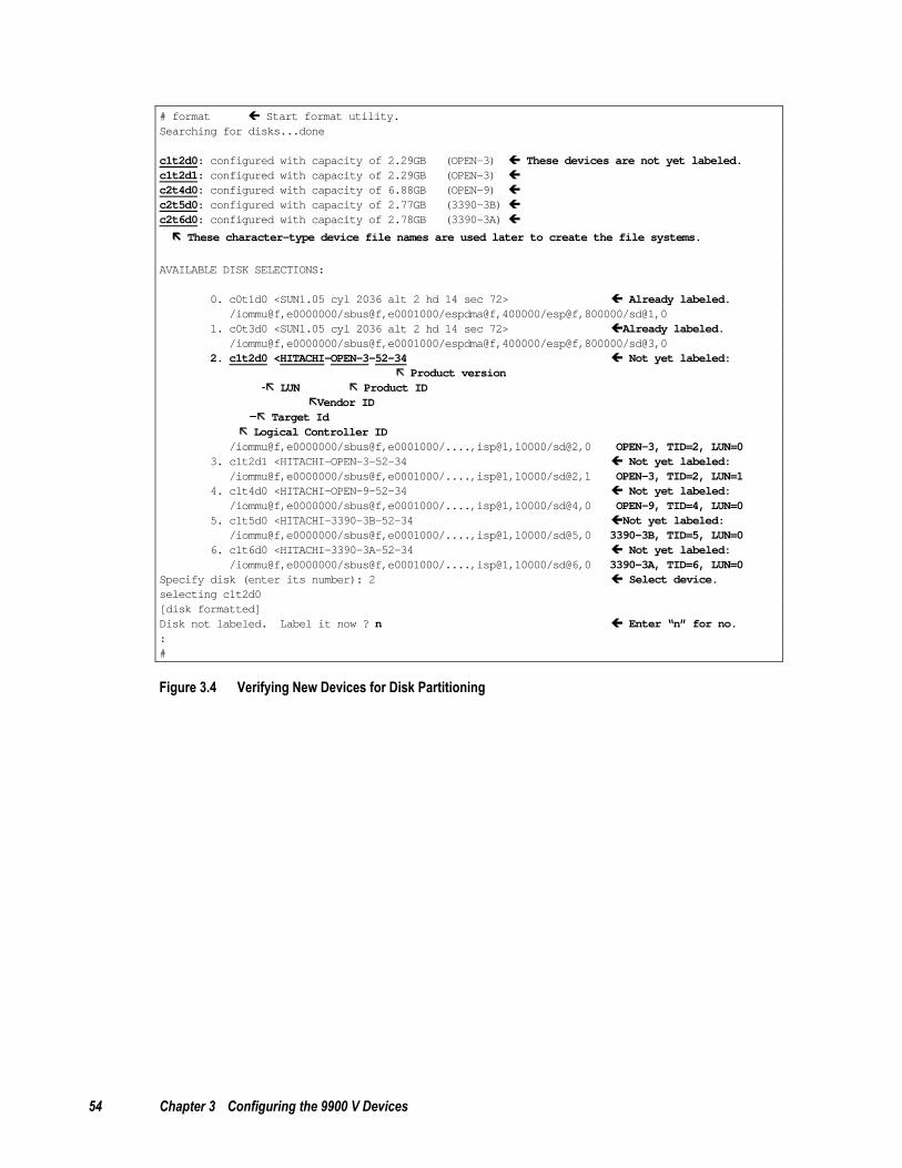
54 Chapter 3 Configuring the 9900 V Devices
# format Start format utility.Searching for disks...done
c1t2d0: configured with capacity of 2.29GB (OPEN-3) These devices are not yet labeled.c1t2d1: configured with capacity of 2.29GB (OPEN-3)c2t4d0: configured with capacity of 6.88GB (OPEN-9)c2t5d0: configured with capacity of 2.77GB (3390-3B)c2t6d0: configured with capacity of 2.78GB (3390-3A)
These character-type device file names are used later to create the file systems.
AVAILABLE DISK SELECTIONS:
0. c0t1d0 <SUN1.05 cyl 2036 alt 2 hd 14 sec 72> Already labeled./iommu@f,e0000000/sbus@f,e0001000/espdma@f,400000/esp@f,800000/sd@1,0
1. c0t3d0 <SUN1.05 cyl 2036 alt 2 hd 14 sec 72> Already labeled./iommu@f,e0000000/sbus@f,e0001000/espdma@f,400000/esp@f,800000/sd@3,0
2. c1t2d0 <HITACHI-OPEN-3-52-34 Not yet labeled:Product version
LUN Product IDVendor ID
Target IdLogical Controller ID
/iommu@f,e0000000/sbus@f,e0001000/....,isp@1,10000/sd@2,0 OPEN-3, TID=2, LUN=03. c1t2d1 <HITACHI-OPEN-3-52-34 Not yet labeled:
/iommu@f,e0000000/sbus@f,e0001000/....,isp@1,10000/sd@2,1 OPEN-3, TID=2, LUN=14. c1t4d0 <HITACHI-OPEN-9-52-34 Not yet labeled:
/iommu@f,e0000000/sbus@f,e0001000/....,isp@1,10000/sd@4,0 OPEN-9, TID=4, LUN=05. c1t5d0 <HITACHI-3390-3B-52-34 Not yet labeled:
/iommu@f,e0000000/sbus@f,e0001000/....,isp@1,10000/sd@5,0 3390-3B, TID=5, LUN=06. c1t6d0 <HITACHI-3390-3A-52-34 Not yet labeled:
/iommu@f,e0000000/sbus@f,e0001000/....,isp@1,10000/sd@6,0 3390-3A, TID=6, LUN=0Specify disk (enter its number): 2 Select device.selecting c1t2d0[disk formatted]Disk not labeled. Label it now ? n Enter “n” for no.:#
Figure 3.4 Verifying New Devices for Disk Partitioning

Hitachi Lightning 9900™ V Series Sun® Solaris™ Configuration Guide 55
FORMAT MENU:disk - select a disktype - select (define) a disk typepartition - select (define) a partition tablecurrent - describe the current diskformat - format and analyze the diskrepair - repair a defective sectorlabel - write label to the diskanalyze - surface analysisdefect - defect list managementbackup - search for backup labelsverify - read and display labelssave - save new disk/partition definitionsinquiry - show vendor, product and revisionvolume - set 8-character volume namequit
# format> type Enter type.
:
AVAILABLE DRIVE TYPES0. Auto configure
:14. SUN2.1G15. HITACHI-OPEN-3-0315 Do not select this disk type.16. other
Specify disk type (enter its number):16 Enter number for “other” to define.Enter number of data cylinders:3336 Enter value from Table 3.1 (*Note 1)Enter number of alternate cylinders[2]:2 Enter value from Table 3.1Enter number of physical cylinders[3338]: (press Enter for default)Enter number of heads:15 Enter value from Table 3.2–Table 3.6Enter number of physical heads[defaults]: (press Enter for default)Enter number of data sectors/track:96 Enter value from Table 3.2–Table 3.6Enter number of physical sectors/track[defaults]: (press Enter for default)Enter rpm of drive [3600]:10000 Enter value from Table 3.1 (*Note 2)Enter format time[defaults]: (press Enter for default)Enter cylinder skew[defaults]: (press Enter for default)Enter track skew[defaults]: (press Enter for default)Enter track per zone[defaults]: (press Enter for default)Enter alternate tracks[defaults]: (press Enter for default)Enter alternate sectors[defaults]: (press Enter for default)Enter cache control[defaults]: (press Enter for default)Enter prefetch threshold[defaults]: (press Enter for default)Enter minimum prefetch[defaults]: (press Enter for default)Enter maximum prefetch[defaults]: (press Enter for default)Enter disk type name(remember quotes):”HITACHI OPEN-3” Enter name from Table 1.1selecting c1t2d0[disk formatted]No defined partition tables.Disk not labeled. Label it now ? n Enter “n” for no.format>
*Note 1: The cylinder number of the 3390-3B is 3346, and the 9900 V returns ‘3346 cylinder’ to the Mode Sense command, and ‘5822040 blocks’ (Maximum LBA 5822039) to Read capacity command. When 3390-3B is not labeled yet, Solaris™ displays 3344 data cylinders and 2 alternate cylinders. When 3390-3B is labeled by the Solaris™ format type subcommand, use 3340 for data cylinder and 2 for alternate cylinder. This is similar to the 3390-3B VLL. *Note 2: The 9900 V reports the RPM of the physical disk drive in response to the type subcommand parameter.
Figure 3.5 Defining and Setting the Disk Type

56 Chapter 3 Configuring the 9900 V Devices
format> disk
AVAILABLE DISK SELECTIONS0. c0t1d0 <SUN1.05 cyl 2036 alt 2 hd 14 sec 72>
/iommu@f,e0000000/sbus@f,e0001000/espdma@f,400000/esp@f,800000/sd@1,01. c0t3d0 <SUN1.05 cyl 2036 alt 2 hd 14 sec 72>
/iommu@f,e0000000/sbus@f,e0001000/espdma@f,400000/esp@f,800000/sd@3,02. c1t2d0 <HITACHI OPEN-3 cyl 3336 alt 2 hd 15 sec 96> ...already labeled
/iommu@f,e0000000/sbus@f,e0001000/....,isp@0,10000/sd@2,03. c1t2d1 <HITACHI-OPEN-3-52-34 .....> ...not yet labeled
/iommu@f,e0000000/sbus@f,e0001000/....,isp@0,10000/sd@2,14. c1t4d0 <HITACHI-OPEN-9-52-34 .....> ...not yet labeled
/iommu@f,e0000000/sbus@f,e0001000/....,isp@1,10000/sd@4,05. c1t5d0 <HITACHI-3390-3B-52-34 ....> ...not yet labeled
/iommu@f,e0000000/sbus@f,e0001000/....,isp@1,10000/sd@5,06. c1t6d0 <HITACHI-3390-3A-52-34 ....> ...not yet labeled
/iommu@f,e0000000/sbus@f,e0001000/....,isp@1,10000/sd@6,0
Specify disk (enter its number): 3
FORMAT MENU:disk - select a disktype - select (define) a disk typepartition - select (define) a partition tablecurrent - describe the current diskformat - format and analyze the diskrepair - repair a defective sectorlabel - write label to the diskanalyze - surface analysisdefect - defect list managementbackup - search for backup labelsverify - read and display labelssave - save new disk/partition definitionsinquiry - show vendor, product and revisionvolume - set 8-character volume namequit
format> type Enter type.
AVAILABLE DRIVE TYPES0.Auto configure
:13. SUN1.3G14. SUN2.1G15. HITACHI-OPEN-3-52-3416. HITACHI OPEN-317. other
Specify disk type (enter its number):16 Enter the number for: the desired drive type.selecting c0t2d0[disk formatted]No defined partition tables.Disk not labeled. Label it now ? n Enter n for no.format>
Figure 3.6 Setting the Partition(s) (continues on the next page)

Hitachi Lightning 9900™ V Series Sun® Solaris™ Configuration Guide 57
FORMAT MENU:disk - select a disktype - select (define) a disk typepartition - select (define) a partition tablecurrent - describe the current diskformat - format and analyze the diskrepair - repair a defective sectorlabel - write label to the diskanalyze - surface analysisdefect - defect list managementbackup - search for backup labelsverify - read and display labelssave - save new disk/partition definitionsinquiry - show vendor, product and revisionvolname - set 8-character volume name<cmd> - execute <cmd>, then returnquit
format> partition Display partition menu.
PARTITION MENU0 - change ‘0’ partition1 - change ‘1’ partition2 - change ‘2’ partition3 - change ‘3’ partition4 - change ‘4’ partition5 - change ‘5’ partition6 - change ‘6’ partition7 - change ‘7’ partitionselect - select a predefined tablemodify - modify a predefined partition tablename - name the current tableprint - display the current tablelabel - write partition map and label to the diskquit
partition> 0 Select partition number.Part Tag Flag Cylinders Size Blocks0 unassigned wm 0 - 0 (0/0/0)
Enter partition id tag [root]: Press enter for default.Enter partition permission flags [wm]: Press enter for default.Enter new starting cyl [0]: Press enter for default.Enter partition size [0b, 0c, 0.00mb]:3336c Enter size (Table 3.1).partition> print Display partition table.: (*See note.)Current partition table (unnamed)Part Tag Flag Cylinders Size Blocks0 root wm 0 - 0 (0/0/0) 01 swap wm 0 - 0 (0/0/0) 02 backup wu 0 - 3335 2.29 GB (3336/0/0) 48038403 unassigned wu 0 - 0 (0/0/0) 04 unassigned wm 0 - 0 (0/0/0) 05 unassigned wm 0 - 0 (0/0/0) 06 usr wm 336 - 3335 204 GB (2970/0/0) 42768007 unassigned wm 0 - 0 (0/0/0) 0
Note: In Solaris™ version 2.6, make sure that partitions 1 and 6 are set to a partition size of 0.
Figure 3.6 Setting the Partition(s) (continued)
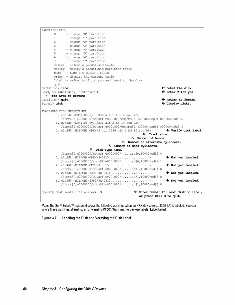
58 Chapter 3 Configuring the 9900 V Devices
PARTITION MENU0 - change ‘0’ partition1 - change ‘1’ partition2 - change ‘2’ partition3 - change ‘3’ partition4 - change ‘4’ partition5 - change ‘5’ partition6 - change ‘6’ partition7 - change ‘7’ partitionselect - select a predefined tablemodify - modify a predefined partition tablename - name the current tableprint - display the current tablelabel - write partition map and label to the diskquit
partition> label Label the disk.Ready to label disk, continue? Y Enter Y for yes.* (see note at bottom)
partition> quit Return to format.format> disk Display disks.
AVAILABLE DISK SELECTIONS0. c0t1d0 <SUN1.05 cyl 2036 alt 2 hd 14 sec 72>
/iommu@f,e0000000/sbus@f,e0001000/espdma@f,400000/esp@f,800000/sd@1,01. c0t3d0 <SUN1.05 cyl 2036 alt 2 hd 14 sec 72>
/iommu@f,e0000000/sbus@f,e0001000/espdma@f,400000/esp@f,800000/sd@3,02. c1t2d0 <HITACHI OPEN-3 cyl 3336 alt 2 hd 15 sec 96> Verify disk label.
Track size.Number of heads.
Number of alternate cylinders.Number of data cylinders.
Disk type name./iommu@f,e0000000/sbus@f,e0001000/....,isp@0,10000/sd@2,0
3. c1t2d1 <HITACHI-OPEN-3-0315 ..................... > Not yet labeled./iommu@f,e0000000/sbus@f,e0001000/....,isp@0,10000/sd@2,1
4. c1t4d0 <HITACHI-OPEN-9-0315 ..................... > Not yet labeled./iommu@f,e0000000/sbus@f,e0001000/....,isp@1,10000/sd@4,0
5. c1t5d0 <HITACHI-3390-3B-0315 .................... > Not yet labeled./iommu@f,e0000000/sbus@f,e0001000/....,isp@1,10000/sd@5,0
6. c1t6d0 <HITACHI-3390-3A-0315 .................... > Not yet labeled./iommu@f,e0000000/sbus@f,e0001000/....,isp@1,10000/sd@6,0
Specify disk (enter its number): 3 Enter number for next disk to label,or press Ctrl-d to quit.
Note: The Sun® Solaris™ system displays the following warnings when an HRX device (e.g., 3390-3A) is labeled. You can ignore these warnings: Warning: error warning VTOC. Warning: no backup labels. Label failed.
Figure 3.7 Labeling the Disk and Verifying the Disk Label

Hitachi Lightning 9900™ V Series Sun® Solaris™ Configuration Guide 59
Table 3.1 9900 V Device Geometry Parameters
Device Type # of Data Cylinders
# of Alternate Cylinders
RPM Partition Size (sample)
OPEN-3 3336 2 10,000 3336c
OPEN-9 10014 2 10,000 10014c
OPEN-E 19757 2 10,000 19757c
OPEN-L 19013 2 10,000 19013c
OPEN-3*n N1* 2 10,000 N4*
OPEN-9*n N5* 2 10,000 N8*
OPEN-E*n N30* 2 10,000 N33*
OPEN-x VLL See Table 1.1 2 10,000 See Table 1.1
OPEN-3*n VLL N22* 2 10,000 N25*
OPEN-9*n VLL N22* 2 10,000 N25*
OPEN-E*n VLL N22* 2 10,000 N25*
OPEN-L*n N34 2 10,000 N37
3390-3A 3346 2 10,000 3346c
3390-3B 3340 2 10,000 3340c
3390-3C 3346 2 10,000 3346c
HRX OPEN-3 3336 2 10,000 3336c
3390-3A VLL See Table 1.1 2 10,000 See Table 1.1
3390-3B VLL See Table 1.1 2 10,000 See Table 1.1
3390-3C VLL See Table 1.1 2 10,000 See Table 1.1
HRX OPEN-3 VLL See Table 1.1 2 10,000 See Table 1.1
* Note: For the values indicated by Nxx (e.g., N15, N22), please refer to Table 3.2–Table 3.6.

60 Chapter 3 Configuring the 9900 V Devices
Table 3.2 Geometry Parameters for OPEN-3*n LUSE Devices
n Data Cylinders-N1 Partition Size-N4
Heads-N2 Blocks/Track-N3
Usable Blocks (N1+2)*N2*N3
Provided Blocks =3338*15*96*n
Diff.
2 6674 15 96 9613440 9613440 0
3 10012 15 96 14420160 14420160 0
4 13350 15 96 19226880 19226880 0
5 16688 15 96 24033600 24033600 0
6 20026 15 96 28840320 28840320 0
7 23364 15 96 33647040 33647040 0
8 26702 15 96 38453760 38453760 0
9 30040 15 96 43260480 43260480 0
10 16688 30 96 48067200 48067200 0
11 20026 33 80 52873920 52873920 0
12 20026 30 96 57680640 57680640 0
13 20026 39 80 62487360 62487360 0
14 23364 30 96 67294080 67294080 0
15 16688 45 96 72100800 72100800 0
16 26702 30 96 76907520 76907520 0
17 30040 34 80 81714240 81714240 0
18 30040 30 96 86520960 86520960 0
19 30040 38 80 91327680 91327680 0
20 16688 60 96 96134400 96134400 0
21 23364 45 96 100941120 100941120 0
22 30040 55 64 105747840 105747840 0
23 30040 46 80 110554560 110554560 0
24 20026 60 96 115361280 115361280 0
25 16688 45 160 120168000 120168000 0
26 20026 39 160 124974720 124974720 0
27 30040 45 96 129781440 129781440 0
28 23364 60 96 134588160 134588160 0
29 30040 58 80 139394880 139394880 0
30 16688 45 192 144201600 144201600 0
31 30040 62 80 149008320 149008320 0
32 26702 60 96 153815040 153815040 0
33 30040 55 96 158621760 158621760 0
34 30040 64 85 163428480 163428480 0
35 30040 56 100 168235200 168235200 0
36 30040 60 96 173041920 173041920 0
N1,N2,N3: Use value in Table 3.1.
N4: Use same value as N1. Specify as NNNNc, where NNNN = # of cylinders and c = cylinder (e.g. enter 6674c for OPEN-3*2).

Hitachi Lightning 9900™ V Series Sun® Solaris™ Configuration Guide 61
Table 3.3 Geometry Parameters for OPEN-9*n LUSE Devices
n Data Cylinders-N5 Partition Size-N8
Heads-N6 Blocks/Track-N7
Usable Blocks (N5+2)*N6*N7
Provided Blocks =10016*15*96*n
Diff.
2 20030 15 96 28846080 28846080 0
3 30046 15 96 43269120 43269120 0
4 30046 20 96 57692160 57692160 0
5 30046 25 96 72115200 72115200 0
6 30046 30 96 86538240 86538240 0
7 30046 35 96 100961280 100961280 0
8 30046 40 96 115384320 115384320 0
9 30046 45 96 129807360 129807360 0
10 30046 50 96 144230400 144230400 0
11 30046 55 96 158653440 158653440 0
12 30046 60 96 173076480 173076480 0
13 30046 52 120 187499520 187499520 0
14 30046 56 120 201922560 201922560 0
15 30046 60 120 216345600 216345600 0
16 30046 64 120 230768640 230768640 0
17 30046 34 240 245191680 245191680 0
18 30046 36 240 259614720 259614720 0
19 30046 38 240 274037760 274037760 0
20 30046 40 240 288460800 288460800 0
21 30046 42 240 302883840 302883840 0
22 30046 44 240 317306880 317306880 0
23 30046 46 240 331729920 331729920 0
24 30046 48 240 346152960 346152960 0
25 30046 50 240 360576000 360576000 0
26 30046 52 240 374999040 374999040 0
27 30046 54 240 389422080 389422080 0
28 30046 56 240 403845120 403845120 0
29 30046 58 240 418268160 418268160 0
30 30046 60 240 432691200 432691200 0
31 30046 62 240 447114240 447114240 0
32 30046 64 240 461537280 461537280 0
33 30985 64 240 475960320 475960320 0
34 31924 64 240 490383360 490383360 0
35 31298 63 256 504806400 504806400 0
36 31689 64 256 519225344 519229440 4096
N5,N6,N7: Use value in Table 3.1, Table 3.2.
N8: Use same value as N5. Specify as NNNNc, where NNNN = # of cylinders and c = cylinder (e.g. enter 20030c for OPEN-9*2).

62 Chapter 3 Configuring the 9900 V Devices
Table 3.4 Geometry Parameters for OPEN-E*n LUSE Devices
n Data Cylinders-N30Partition Size-N33
Heads-N31 Blocks/Track-N32
Usable Blocks (N30+2)*N31*N32
Provided Blocks =9966*15*96*n
Diff.
2 19757 30 96 56905920 56905920 0
3 19757 45 96 85358880 85358880 0
4 19757 60 96 113811840 113811840 0
5 19757 30 240 142264800 142264800 0
6 19757 45 192 170717760 170717760 0
7 19757 60 168 199170720 199170720 0
8 19757 60 192 227623680 227623680 0
9 19757 60 216 256076640 256076640 0
10 19757 60 240 284529600 284529600 0
11 27166 60 192 312975360 312982560 7200
12 29636 60 192 341429760 341435520 5760
13 32106 60 192 369884160 369888480 4320
14 27660 60 240 398332800 398341440 8640
15 29636 60 240 426787200 426794400 7200
16 31612 60 240 455241600 455247360 5760
17 31612 60 255 483694200 483700320 6120
18 31257 64 256 512147456 512153280 5824
N30,N31,N32 : Use value in Table 3.1.
N33 : Use same value as N30. Specify as NNNNc, where NNNN = # of cylinders and c = cylinder (e.g. enter 19757c for OPEN-E*2).
Note: Data cylinders must be less than or equal to 32767, heads must be less than or equal to 64, blocks per track must be less than or equal to 256 when these values are specified as parameters of Solaris™ format type subcommand. The whole data blocks of OPEN-E*2∼ OPEN-E*10 can be used by above parameters. About OPEN-E*11~OPEN-E*18, some blocks must become unusable.
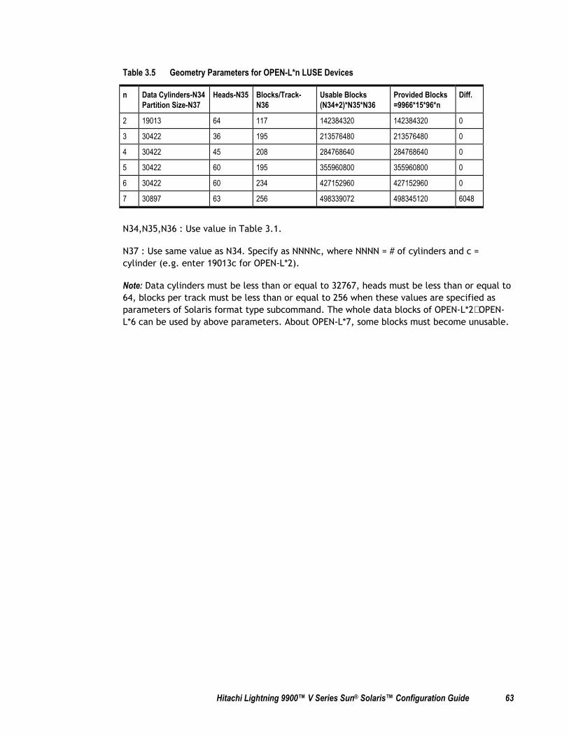
Hitachi Lightning 9900™ V Series Sun® Solaris™ Configuration Guide 63
Table 3.5 Geometry Parameters for OPEN-L*n LUSE Devices
n Data Cylinders-N34 Partition Size-N37
Heads-N35 Blocks/Track-N36
Usable Blocks (N34+2)*N35*N36
Provided Blocks =9966*15*96*n
Diff.
2 19013 64 117 142384320 142384320 0
3 30422 36 195 213576480 213576480 0
4 30422 45 208 284768640 284768640 0
5 30422 60 195 355960800 355960800 0
6 30422 60 234 427152960 427152960 0
7 30897 63 256 498339072 498345120 6048
N34,N35,N36 : Use value in Table 3.1.
N37 : Use same value as N34. Specify as NNNNc, where NNNN = # of cylinders and c = cylinder (e.g. enter 19013c for OPEN-L*2).
Note: Data cylinders must be less than or equal to 32767, heads must be less than or equal to 64, blocks per track must be less than or equal to 256 when these values are specified as parameters of Solaris format type subcommand. The whole data blocks of OPEN-L*2∼ OPEN-L*6 can be used by above parameters. About OPEN-L*7, some blocks must become unusable.

64 Chapter 3 Configuring the 9900 V Devices
Table 3.6 Geometry Parameters for OPEN-x*n VLL-LUSE Devices (Example)
# Data Cylinders-N22 Partition Size-N25
Heads-N23
Blocks/Track-N24
Usable Blocks (N22+2)*N23*N24
Provided Blocks-N21 Diff.
1 98 15 96 144000 35MB×2 volumes ↑35×1024/720↑×2=100 100×15×96=144000
0
2 2590 15 96 3732480 50MB×36 volumes ↑50×1024/720↑×36=2592 2592×15×96=3732480
0
3 284 15 96 411840 100MB×2 volumes ↑100×1024/720↑×2=286 286×15×96=411840
0
4 5694 15 96 8202240 500MB×8 volumes ↑500×1024/720↑×8=5696 5696×15×96=8202240
0
5 22758 30 96 65548800 2000MB×2 volumes ↑2000×1024/720↑×16=45520 45520×15×96=65548800
0
6 27455 40 188 206476640 2800MB×36 volumes ↑2800×1024/720↑×36=143388 143388×15×96=206478720
2080
N21 # of blocks of LUSE composed by VLL volumes are calculated by : N21 = N20 × (# of heads) × (# of sectors per track).
N22: N20 – 2, Use total cylinder - 2.
N23,N24: Use value in Table 3.1, Table 3.2.
N25: Use same value as N22.

Hitachi Lightning 9900™ V Series Sun® Solaris™ Configuration Guide 65
3.4 Creating and Mounting the File Systems
After you have partitioned and labeled all new disks, you can create and mount the file systems for the SCSI disk devices (e.g., OPEN-x). Creating and mounting the file systems for the new SCSI disk devices involves:
Creating the file systems (see section 3.4.1),
Creating and verifying the mount directories (see section 3.4.2),
Mounting and verifying the file systems (see section 3.4.3),
Setting the auto-mount parameters (optional) (see section 3.4.4).
Note: Do not create file systems or mount directories for the HRX devices (e.g., 3390-3A). These devices are accessed as raw devices and do not require any further configuration after being partitioned and labeled.
3.4.1 Creating the File Systems
To create the file systems for the newly installed SCSI disk devices:
1. Create the file system using the newfs -C <maxcontig> command (see Figure 3.8).
a) Use 6 or one of the following multiples of 6 as the maxcontig value for all 9900 V SCSI disk devices: 12, 18, 24, or 30. If 6 is used, Solaris™ will access 48 kB as a unit (6 × 8 kB), which matches the track size of the 9900 V OPEN-3 and OPEN-9 devices. These maxcontig values (6, 12, 18, 24, 30) optimize the 9900 V’s I/O performance by keeping the I/O data range on one track. The maxcontig value that you choose depends on your applications, and you can always change the maxcontig parameter to a different value at any time.
b) Use the character-type device file as the argument (e.g., /dev/rdsk/c1t2d0s0).
2. When the confirmation appears, verify that the device file name is correct. If so, enter y for yes. If not, enter n for no, and then repeat step (1) using the correct device file name.
3. Repeat steps (1) and (2) for each new SCSI disk device on the 9900 V subsystem. Make sure to use the same maxcontig value for all 9900 V devices.
# newfs -C 6 /dev/rdsk/c1t2d0s0 Create file system.newfs:construct a new file system /dev/rdsk/c1t2d0s0:(y/n) y Verify correct device./dev/rdsk/c1t2d0s0: 4803840 sectors in 3336 cylinders of 15 tracks, 96 sectors
2345.6MB in 209 cyl groups (16 c/g, 11.25MB/g, 5440 i/g)super-block backups (for fsck -F ufs -o b=#) at:32, 23168, 46304, 69440, 92576, 115712, 138848, 161984, 185120, 208256,:
4747616, 4770752, 4792352,# newfs -C 6 /dev/rdsk/c1t2d1s0 Create file system on
next disk using samemaxcontig value.
Figure 3.8 Creating the File Systems

66 Chapter 3 Configuring the 9900 V Devices
3.4.2 Creating and Verifying the Mount Directories
After you have created the file systems, you can create and verify the mount directories for the new SCSI disk devices. Each logical partition requires a unique mount directory, and the mount directory name should identify the logical volume and the partition.
To create the mount directories for the newly installed SCSI disk devices:
1. Go to the root directory ( Figure 3.9).
2. Create the mount directory using the mkdir command. Choose a name for the mount directory which identifies both the logical volume and the partition. For example, to create a mount directory named 9900 V_LU00, enter: mkdir /9900 V_LU00
Note: If you need to delete a mount directory, use rmdir (e.g., rmdir /9900 V_LU00).
3. Verify the new mount directory using the ls -x command.
4. Repeat steps (2) and (3) for each logical partition on each new SCSI disk device.
# cd Go to the root directory.# pwd Display current directory./# mkdir /9900 V_LU00 Create new mount directory.# ls -x Verify new mount directory.9900 V_LU00 bin dev device etc export correctlyfloppy home hstsboof kadb kernel lib#
Figure 3.9 Creating and Verifying a Mount Directory
3.4.3 Mounting and Verifying the File Systems
After you have created the mount directories, you can mount and verify the file systems for the new SCSI disk devices. The file system for each logical partition should be mounted and verified to ensure that all new logical units are fully operational.
To mount and verify the file systems for the newly installed 9900 V devices (see Figure 3.10).
1. Mount the file system using the mount command. Make sure to use the correct block-type device file name and mount directory for the device/partition. For example, to mount the file /dev/dsk/c1t2d0s0 with the mount directory /9900 V_LU00 enter: mount /dev/dsk/c1t2d0s0 /9900 V_LU00
If you need to unmount a file system, use umount command (e.g., umount /9900 V_LU00).
Note: If you have already set the auto-mount parameters (see section 3.4.4), you do not need to specify the block-type device file, only the mount directory.
2. Repeat step (1) for each partition of each newly installed SCSI disk device.

Hitachi Lightning 9900™ V Series Sun® Solaris™ Configuration Guide 67
3. Display the mounted devices using the df -k command, and verify that all new SCSI disk devices are displayed correctly. OPEN-x devices will display as OPEN-3, OPEN-9, OPEN-E, or OPEN-L devices.
4. As a final verification, perform some basic UNIX® operations (e.g., file creation, copying, and deletion) on each logical unit to make sure that the new file systems are fully operational.
# mount /dev/dsk/c1t2d0s0 /9900 V_LU00 Mount file system.
Block-type device file name
# mount /dev/dsk/c1t2d1s0 /9900 V_LU01 Mount next filesystem.
Mount directory name
# mount /dev/dsk/c1t2d2s0 /9900 V_LU02 Mount next file system.::## df -k Display file systems.File system Kbytes used avail capacity Mounted on/dev/dsk/c0t3d0s0 28775 27706 0 100% //dev/dsk/c0t3d0s6 269191 234897 7384 97% /usr/proc 0 0 0 0% /procfd 0 0 0 0% /dev/fd/dev/dsk/c0t3d0s4s 57567 29515 22302 57% /varswap 142204 20 142184 0% /tmp/dev/dsk/c0t3d0s7 462119 206000 209909 50% /export/home/dev/dsk/c0t3d0s5 47975 42059 1126 97% /opt/dev/dsk/c1t2d0s0 2256436 9 2030787 0% /9900 V_LU00 Verify filesystems./dev/dsk/c1t2d1s0 2256436 9 2030787 0% /9900 V_LU01 OPEN-3device/dev/dsk/c1t2d2s0 6774358 9 6548709 0% /9900 V_LU02 OPEN-9device:# mount /dev/dsk/c1t2d0s0 /9900 V_LU00 Mount file system.# cd /9900 V_LU00 Go to mount directory.# cp /bin/vi /9900 V_LU00/vi.back1 Copy a file.# ls -l Verify the file copy.drwxr-xr-t 2 root root 8192 Mar 15 11:35 lost+found-rwxr-xr-x 1 root sys 2617344 Mar 15 11:41 vi.back1# cp vi.back1 vi.back2 Copy file again.# ls -l Verify file copy again.drwxr-xr-t 2 root root 8192 Mar 15 11:35 lost+found-rwxr-xr-x 1 root sys 2617344 Mar 15 11:41 vi.back1-rwxr-xr-t 1 root sys 2617344 Mar 15 11:52 vi.back2# rm vi.back1 Remove test files.# rm vi.back2
Figure 3.10 Mounting and Verifying the File System

68 Chapter 3 Configuring the 9900 V Devices
3.4.4 Setting and Verifying the Auto-Mount Parameters
You can add any or all of the new SCSI disk devices to the /etc/vfstab file to specify the auto-mount parameters for each device. Once a device is added to this file, you can mount the device without having to specify its block-type device file name (e.g., mount /9900 V_LU00), since the /etc/vfstab file associates the device with its mount directory.
To set the auto-mount parameters for the desired devices (see Figure 3.11).
1. Make a backup copy of the /etc/vfstab file: cp /etc/vfstab /etc/vfstab.standard
2. Edit the /etc/vfstab file to add one line for each device to be auto-mounted. Table 3.7 shows the auto-mount parameters. If you make a mistake while editing, exit the vi editor without saving the file, and then begin editing again.
3. Reboot the Sun® system after you are finished editing the /etc/vfstab file.
4. Display the mounted devices using the df -k command, and verify that the desired devices were auto-mounted.
# cp -ip /etc/vfstab /etc/vfstab.standard Make backup before editing.# vi /etc/vfstab Edit the file.#device device mount FS fsck mount mount#to mount to fsck point type pass at boot options
SeeTable 3.7.
/proc - /proc procfs - no -fd - /dev/fd fd - no -swap - /tmp tmpfs - yes -/dev/dsk/c0t3d0s0 /dev/rdsk/c0t3d0s0 / ufs 1 no -/dev/dsk/c0t3d0s6 /dev/rdsk/c0t3d0s6 /usr ufs 2 no -/dev/dsk/c0t3d0s7 /dev/rdsk/c0t3d0s7 /export ufs 3 yes -/dev/dsk/c0t3d0s5 /dev/rdsk/c0t3d0s5 /opt ufs 4 yes -/dev/dsk/c0t3d0s1 - - swapfs - no -/dev/dsk/c1t2d0s0 /dev/rdsk/c1t2d0s0 /9900 V_LU00 ufs 5 yes - Addone line/dev/dsk/c1t2d1s0 /dev/rdsk/c1t2d1s0 /9900 V_LU01 ufs 5 yes - foreach LUN.
Figure 3.11 Setting the Auto-Mount Parameters
Table 3.7 Auto-Mount Parameters
Parameter # Name Enter:
Device to mount Block-type device file name
Device to fsck Character-type device file name
Mount point Mount directory name
FS type File system type (e.g., ufs)
Fsck pass Order for performing file system checks
Mount at boot Yes = auto-mounted at boot/mountall No = not auto-mounted at boot/mountall
Mount options Desired mount options: - no options (typical) -ro read-only access (e.g., for 3390- 3B devices)

Hitachi Lightning 9900™ V Series Sun® Solaris™ Configuration Guide 69
Chapter 4 Failover and SNMP Configuration
The Lightning 9900™ V Series subsystem supports industry-standard products and functions which provide host and/or application failover, I/O path failover, and logical volume management (LVM). For the Sun® Solaris™ environment, the 9900 V subsystem supports the following products and functions (please contact Hitachi Data Systems for the latest information):
VERITAS® Cluster Server™ and Sun™ Cluster for host/application failover (section 4.1).
Hitachi Dynamic Link Manager (HDLM) and VERITAS® Volume Manager™ for path failover and logical volume management (see section 4.2).
The 9900 V disk subsystem also supports the industry-standard simple network management protocol (SNMP) for remote subsystem management from the UNIX®/PC server host. SNMP is used to transport management information between the 9900 V SVP and the SNMP manager on the host. The SNMP agent on the SVP sends status information to the host(s) when requested by the host or when a significant event occurs.
Note: The user is responsible for configuring the failover and SNMP management software on the UNIX®/PC server host. For assistance with failover and/or SNMP configuration on the host, please refer to the user documentation, or contact the vendor’s technical support.
4.1 Host Failover
The 9900 V subsystem supports the VERITAS® Cluster Server™ and Sun™ Cluster host failover products for the Sun® Solaris™ operating system. The user must make sure to configure the host failover software and any other high-availability (HA) software as needed to recognize and operate with the newly attached 9900 V devices.
Note: You must set HOST MODE=09 before installing SUN CLUSTER, or the Quorum Device will not be assigned to the 9900 V subsystem.
Note: When Sun Cluster 3.0 is used, you must set HOST MODE=09 and System Option Mode 185=ON. When MODE 185=ON is set, a unique disk ID is assigned for each LUN. When MODE 185=OFF is set, the same disk ID is assigned for all LUNs.
For assistance with VERITAS® Cluster Server™ operations, please refer to the VERITAS® user documentation, or contact VERITAS® technical support. For assistance with Sun™ Cluster operations, please refer to the Sun™ Cluster user documentation, or contact Sun® technical support. For assistance with specific configuration issues related to the 9900 V subsystem, please contact your Hitachi Data Systems representative.
4.2 Path Failover
The 9900 V subsystem supports the Hitachi Dynamic Link Manager (HDLM) and VERITAS® Volume Manager™ path failover products for the Sun® Solaris™ operating system. The user must make sure to configure the path failover software and any other products as needed to recognize and operate with the newly attached 9900 V devices.

70 Chapter 4 Failover and SNMP Configuration
For assistance with Hitachi Dynamic Link Manager for Solaris™ systems, please refer to the Hitachi Freedom Storage™ Hitachi Dynamic Link Manager User’s Guide for Solaris™ (MK-92DLM114), or contact your Hitachi Data Systems representative. For assistance with VERITAS® Volume Manager™ operations, please refer to the VERITAS® user documentation, or contact VERITAS® technical support.
4.3 SNMP Remote Subsystem Management
SNMP is a part of the TCP/IP protocol suite that supports maintenance functions for storage and communication devices. The 9900 V subsystem utilizes SNMP to transfer status and management commands to the SNMP Manager on the UNIX®/PC server host via the 9900 V SVP (see Figure 4.1). When the SNMP manager requests status information or when a service information message (SIM) occurs, the SNMP agent on the 9900 V SVP notifies the SNMP manager on the UNIX®/PC server. Notification of 9900 V error conditions is made in real time, providing the UNIX®/PC server user with the same level of monitoring and support available to the mainframe user. The SIM reporting via SNMP enables the user to monitor the 9900 V subsystem from the UNIX®/PC server host.
When a SIM occurs, the 9900 V SNMP agent initiates trap operations, which alert the SNMP manager of the SIM condition. The SNMP manager receives the SIM traps from the SNMP agent, and can request information from the SNMP agent at any time.
Note: The user is responsible for configuring the SNMP manager on the Sun® Solaris™ server host. For assistance with SNMP manager configuration on the Sun® Solaris™ server host, please refer to the user documentation, or contact the vendor’s technical support.
SIM Private LAN
Error Info. Public LAN
SNMP Manager
SVP UNIX/PC Server
Figure 4.1 9900 V SNMP Environment

Hitachi Lightning 9900™ V Series Sun® Solaris™ Configuration Guide 71
Chapter 5 Troubleshooting
5.1 Troubleshooting
The Hitachi Lightning 9900™ V Series disk array subsystems provide continuous data availability. For troubleshooting information on the 9900 V subsystem, please refer to the Hitachi Lightning 9900™ V Series User and Reference Guide (MK-92RD100).
One method of troubleshooting for Solaris™ operations involves the “verbose” mode for the HBA configuration file. See section 5.2 for information on verbose mode troubleshooting.
Table 5.1 lists potential error conditions during 9900 V Sun® Solaris™ configuration and provides instructions for resolving each condition. If you are unable to resolve an error condition, please contact your Hitachi Data Systems representative for help, or call the Hitachi Data Systems Support Center for assistance.
Table 5.1 Troubleshooting
Error Condition Recommended Action
The logical devices are not recognized by the system.
Make sure that the READY indicator lights on the 9900 V subsystem are ON. Make sure that the fibre cables are correctly installed and firmly connected. Run dmesg to recheck the fibre buses for new devices. Verify the contents of /kernel/drv/sd.conf file. Make sure that LUSE devices are not intermixed with normal LUs or with multiplatform devices on the same port.
File system cannot be created (newfs command)
Check that character-type device file is specified for newfs command. Verify that logical unit is correctly labeled by UNIX® format command.
The file system is not mounted after rebooting.
Make sure that the system was restarted properly. Make sure that the file system attributes are correct. Verify that /etc/vfstab is correctly edited.
Pinned track. Reset ECC/LRC pinned track error status using the Solaris™ analyze command as described in Appendix A.
The Sun® system does not reboot properly after hard shutdown.
If the Sun® system is powered off without executing the shutdown process, wait three minutes before restarting the Sun® system. This allows the 9900 V’s internal time-out process to purge all queued commands so that the 9900 V is available (not busy) during system startup. If the Sun® system is restarted too soon, the 9900 V will continue trying to process the queued commands, and the Sun® system will not reboot successfully.
The 9900 V performed a self reboot because the subsystem was busy or it logged a panic message.
Reboot the Sun® system.
The 9900 V responds Not Ready, or the 9900 V has displayed Not Ready and timed itself out.
Please contact the Hitachi Data Systems Support Center.
The system detects a parity error. Make sure that the HBA has been installed properly. Reboot the Sun® system.

72 Chapter 5 Troubleshooting
5.2 Verbose Mode
One method of troubleshooting involves the “verbose” mode for the HBA configuration file. The following paragraphs are examples of error messages that may occur. A possible debugging method is to select the device and turn on verbose mode, then attempt the boot process again. Verbose error messages will provide information which will help isolate the problem. Use the steps in Figure 5.1 to turn on the verbose flag. Figure 5.2 contains examples of error messages.
ok “ /sbus/fca” select-devok true to fca-verboseok boot fcadisk
Figure 5.1 Turning on Verbose Flag
Error message:Cannot Assemble drivers for /sbus@1f,0/fcaw@1,0/sd@0,0:aCannot Mount root on /sbus@1f,0/fcaw@1,0/sd@0,0:aProblem:The process of copying the OS to the fibre channels was not complete, or the drivespecified on the boot command is not the same as the one the OS was constructed on.
Error message:Can’t open boot deviceProblem:The wwn specifed with the set-bootn0-wwn does not correspond to the wwn of the device.Could also be a cable problem – the adapter cannot initialize.
Error message:The file just loaded does not appear to be bootableProblem:The bootblk was not installed on the target.
Error message:mount: /dev/dsk/c0t0d0s0 – not of this fs typeProblem:At this point the process hangs. This happens if the /etc/vfstabFile has not been updated on the fibrechannel boot drive to reflect the new target.
Error message:Get PortID request rejected by nameserverProblem:The wwn of the target is not correct. Select the adapter and perform set-bootn0-wwn. Ifthis is correct, check the switch to see that target is properly connected.
Error message:Can’t read disk labelProblem:The selected target is not a Solaris filesystem.
Figure 5.2 Examples of Error Messages (continues on the next page)

Hitachi Lightning 9900™ V Series Sun® Solaris™ Configuration Guide 73
Error message:Nport init failed –Problem:Card is connected to an arbitrated loop device, but wants to initialize as an NPORT. Thebootn0-wwn property has probably been set to a valid WWN.
Error message:Panic dump not savedProblem:After the system is successfully booted to Solaris from the fibrechannel and a panic occursthe panic does not get saved to the swap device.This can be the result not properly defined the swap partition.Use the format command to view the slices on the fibre channel drive.Take the partition option, then the print option.The swap partition should look something like this:
1 swap wm 68-459 298.36MB (402/0/0) 611040Sizes and cylinders will probably be different on your system. Make sure that the flag iswm and that the sizes are defined (not 0). Then use the label option from partition towrite the label to the drive. After this the panic should be saved to the swap partition.If the partition needs to be changed chose the partition option, and enter 1 to selectslice 1.
Error message:Can’t open /packagesProblem:The bootblk was not properly installed
Figure 5.2 Examples of Error Messages (continued)

74 Chapter 5 Troubleshooting
5.3 Calling the Hitachi Data Systems Support Center
If you need to call the Hitachi Data Systems Support Center, make sure to provide as much information about the problem as possible, including the circumstances surrounding the error or failure and the exact content of any error messages displayed on the host system(s). Please note the reference codes and severity levels of the recent 9900 V SIMs.
The worldwide Hitachi Data Systems Support Centers are:
Hitachi Data Systems North America/Latin America San Diego, California, USA 1-800-348-4357 1-619-537-3000
Hitachi Data Systems Europe Contact Hitachi Data Systems Local Support
Hitachi Data Systems Asia Pacific North Ryde, Australia 011-61-2-9325-3300

Hitachi Lightning 9900™ V Series Sun® Solaris™ Configuration Guide 75
Appendix A Pinned Track Recovery
To recover a pinned track on a 9900 V device, use the analyze command in the format utility to write dummy data to the pinned track as shown in Figure A.1. This procedure is used for Sun® Solaris™ 2.6 and may not be valid for other versions of the Solaris™ OS. Make sure that you check the device number in the SCSI path configuration and not the 9900 V LDEV ID.
WARNING: Data written on a pinned track or data on the partition containing the pinned track will be overwritten by the dummy data write process. The pinned track data or partition data should be restored using a backup file.
To recover a pinned track:
1. Log in to the Solaris™ system as root.
2. Write dummy data to the pinned track using the analyze command (analyze is a subcommand of the format command).
3. Isolate LDEV number of the LDEV containing the pinned track by SVP.
4. Get the SCSI port number (1A∼ 2H), SCSI target ID and LUN on the Solaris™ system for the LDEV having the pinned track.
5. Log in to the Solaris™ system as root, and execute the format command.
6. Determine device number cxtxdx by port number and target ID and LUN and the board installed into the Sun® system to which the 9900 V port is connected.
7. The whole track range must be specified by starting LBA and ending LBA.
8. One track has 96 blocks for OPEN-x, OPEN-x*n (LUSE), and OPEN-x .
9. The pinned track will not be correctly reset if the whole track range is not specified.
10. Data written on the pinned track must be recovered by backup file because the analyze command writes dummy data on the pinned track.
11. The files or directories written with dummy data cannot be determined because of the structure of the UNIX® file system. All files and directories on the partition containing the pinned track must be recovered from the backup file.

76 Appendix A Pinned Track Recovery
host console login: root Log in as root.password: hitachi Enter your password.# format Enter format.Searching for disks...doneAVAILABLE DISK SELECTIONS::
Specify disk (enter its number):1 Enter the pinned trackselecting cxtxdx disk number.[disk formatted]
FORMAT MENU::
format> analyze Enter analyze.:
analyze> setup Enter setup.Analyze entire disk[yes]? N Enter N for no.Enter starting block number[0, 0/0/0]: starting LBA of the pinned trackEnter ending block number[5806479, 3336/14/115]: ending LBA of the trackLoop continuously[no] no Enter no.Enter number of passes[2] Press enter for default.Repair defective blocks[yes] Press enter for default.Stop after first error[no] Press enter for default.Use random bit patterns[no] Press enter for default.Enter number of blocks per transfer[126, 0/1/10]: 1 Enter 1.Verify media after formatting [yes]? no Enter no.Enable extended messages[no]? yes Enter yes.estore defect list[yes]? Press enter for default.Restore disk label[yes]? Press enter for default.
analyze> write Enter write.Ready to analyze (will corrupt data). This takes a long time,but is interruptable with CTRL-C. Continue? y Enter y for yes.
PASS 0 - pattern = c6dec6decylinder number/head number/block counts
Total of 0 defective blocks repaired.analyze> quit Exit the analyze utility.
Figure A.1 Recovering a Pinned Track

Hitachi Lightning 9900™ V Series Sun® Solaris™ Configuration Guide 77
Appendix B Fibre Port Addressing
In a FC-AL (fibre channel arbitrated loop) configuration, the host communicates with the devices comprising the loop with 8 bit AL-PA (arbitrated loop physical address, also called the port address). The number of available port addresses is 126. (There are 127 port addresses, but address 00H is reserved for fibre connection.)
Devices communicate with hosts using individual port addresses. However, hosts map SCSI protocol to fibre channel devices. The hosts access the device’s LUs using the device files /dev/dsk/c*t*d* and /dev/rdsk/c*t*d*. SCSI and fibre channel devices are accessed the same way; however, the device files for SCSI and fibre channel devices are configured differently. Table B.1 lists the AL-PA and the corresponding SCSI address.
Table B.1 Fibre Port Addressing (continues on next page)
AL-PA T value AL-PA T value AL-PA T value AL-PA T value
EF 0 CD 16 B2 32 98 48
E8 1 CC 17 B1 33 97 49
E4 2 CB 18 AE 34 90 50
E2 3 CA 19 AD 35 8F 51
E1 4 C9 20 AC 36 88 52
E0 5 C7 21 AB 37 84 53
DC 6 C6 22 AA 38 82 54
DA 7 C5 23 A9 39 81 55
D9 8 C3 24 A7 40 80 56
D6 9 BC 25 A6 41 7C 57
D5 10 BA 26 A5 42 7A 58
D4 11 B9 27 A3 43 79 59
D3 12 B6 28 9F 44 76 60
D2 13 B5 29 9E 45 75 61
D1 14 B4 30 9D 46 74 62
CE 15 B3 31 9B 47 73 63

78 Appendix B Fibre Port Addressing
Table B.1 Fibre Port Addressing (continued)
AL-PA T value AL-PA T value AL-PA T value AL-PA T value
72 64 55 80 3A 96 23 112
71 65 54 81 39 97 23 113
6E 66 53 82 36 98 1F 114
6D 67 52 83 35 99 1E 115
6C 68 51 84 34 100 1D 116
6B 69 4E 85 33 101 1B 117
6A 70 4D 86 32 102 18 118
69 71 4C 87 31 103 17 119
67 72 4B 88 2E 104 10 120
66 73 4A 89 2D 105 0F 121
65 74 49 90 2C 106 08 122
63 75 47 91 2B 107 04 123
5C 76 46 92 2A 108 02 124
5A 77 45 93 29 109 01 125
59 78 43 94 27 110
56 79 3C 95 26 111

Hitachi Lightning 9900™ V Series Sun® Solaris™ Configuration Guide 79
Appendix C Online Device Installation
This appendix provides instructions for online installation of new devices. After initial installation and configuration of the Lightning 9900™ V Series subsystem, additional devices can be installed or de-installed online without having to restart the Solaris™ system. After online installation, the device parameters for new volumes must be changed to match the LUs defined under the same fibre-channel port (see section 3.2). This procedure should be performed by the system administrator (i.e., super-user).
Note: For additional instructions regarding online installation and deinstallation of LUs, please refer to the 9900 V Maintenance Manual or the Hitachi Lightning 9900™ V Series LUN Manager User’s Guide (MK-92RD105).
When the TOV for 9900 V volumes needs to be changed, you must edit the /etc/system file and reboot to make the file change effective. Please use normal disruptive installation procedure for this case. Solaris™ must be booted once by the boot -r command with the TIDs and LUNs for new volumes defined in /kernel/drv/sd.conf file for non-disruptive volume installation. It is one way to prepare future online volume installation that whole TIDs and LUNs, i.e. TID=0∼ 15 and LUN=0∼ 7 are defined in the Solaris™ kernel/drv/sd.conf file and the system is once booted with boot -r command. In case of fibre channel, you should define LUN=0~119 in /kernel/drv/sd.conf file for the path (TID) which you will install additional LUNs.
Note: With the JNI™ Emerald™-based FC host bus adapter, online installation is not available.
1. The Solaris™ system must be booted once by boot -r command with the TIDs and LUNs for new volumes defined in /kernel/drv/sd.conf file for non-disruptive volume installation. If not, the Solaris™ system must be rebooted to recognize new volumes.
2. Check existing SCSI TIDs.
3. Hitachi Lightning 9900™ V Series setup:
a) Ensure the latest microcode is loaded. Non-disruptive version up requires alternate path.
b) Install CHF and LDEV, and connect fibre cable if necessary.
c) Execute online LU installation from the SVP or using the Remote Console – Storage Navigator software.
d) Verify 9900 V SCSI path configuration.
4. Execute the following commands (as super-user) to recognize the new devices. # /usr/sbin/drvconfig # /usr/sbin/devlinks # /usr/sbin/disks # /usr/ucb/ucblinks
5. After online installation, the device parameters (e.g., TOV, queue depth) for the new volumes must be changed to match the LUs defined under the same fibre-channel port.
6. Configure the new devices (partition, label, file system, auto-mount) as described in Chapter 3.

80 Appendix C Online Device Installation

Hitachi Lightning 9900™ V Series Sun® Solaris™ Configuration Guide 81
Appendix D Configuring the Boot Disk on the 9900 V
D.1 Introduction
The Solaris™ boot disk can be configured on the Hitachi Lightning 9900™ V Series if the following conditions are met:
Host bus adapter must be JNI™ 64-bit S-Bus FC Adapter.
FCODE (firmware) version of HBA must be 13.3.5 for Solaris™ 2.6/7 and 13.3.7 for Solaris™ 8.
FCA driver version must be 2.2.1.HIT.06.01 for Solaris™ 2.6/7 and 2.5.8.HIT.07 for Solaris™ 8.
Fibre-channel topology must be FC-AL. The EPL mode of FC switching hub is not available. Connecting to Fabric Switch is not available.
Open Boot version must be 3.1 or later.
Install the JNI™ adapter card and the fibre channel disk drive on a Sparc® workstation running the desired OS. Install the JNI™ software, and verify that the OS sees the fibre channel drives. Identify the controller and target for the installation of the Solaris™ OS. The target ID must be in the range 0-9.
Note: The Solaris™ system sometimes changes the adapter and controller instance number during a boot –r. If the target for the root file system is set to c2t0d0s0 in /etc/vfstab, but the reconfiguration boot changes the controller number to c3, the boot will fail. Before installing Solaris™ on the fibre-channel driver, start with a clean system. Make sure the adapter is the first instance (fca0 or fcaw0). This may require a boot -ar to initialize the /etc/path_to_inst file.
Note the worldwide name (wwn) of the target. The wwn is printed by the driver during the attach phase. It can be seen in the console window, or by viewing the /var/adm/messages file. You may use the target to world wide name binding feature for the driver to set the wwn in the /kernel/drv/sd.conf file. This is strongly recommended if the topology includes a switch or hub where configuration is subject to change. See the technotes accompanying the Solaris™ device driver for details.
Note: When the subsystem is set up as boot disk for the Solaris™ system, it is necessary to stop I/O operation for hosts connected to the subsystem. It is recommended that Solaris™ boot be performed during low host load periods.

82 Appendix D Configuring the Boot Disk on the 9900 V
D.2 Partition Check
To configure the Solaris™ boot disk on the 9900 V, use the format command to verify that the target will accommodate the Sun® OS partitions. Verify that the sizes of the partitions on the target chosen for the Solaris™ installation are large enough to copy the current OS partitions. Use the format command to examine the partitions of the system drives where the current OS resides (see Figure D.1).
# format(choose disk 0)
format> partitionpartition> print
(sample output:)Current partition table (original):Total disk cylinders available: 2733 + 2 (reserved cylinders)
Part Tag Flag Cylinders Size Blocks0 root wm 0 - 133 99.45MB (134/0/0) 2036801 swap wu 134 - 241 80.16MB (108/0/0) 1641602 backup wm 0 - 2732 1.98GB (2733/0/0) 41541603 unassigned wm 0 0 (0/0/0) 04 unassigned wm 0 0 (0/0/0) 05 unassigned wm 0 0 (0/0/0) 06 usr wm 242 - 761 385.94MB (520/0/0) 7904007 home wm 762 - 2732 1.43GB (1971/0/0) 2995920
quit partition, and choose the fibre channel disk on which you wish to install the OS.
partition> quitformat> disk
AVAILABLE SELECTIONS ---specify disk:(Enter number of disk)1 (example)
format> partitionpartition> print
Repartition the drive (if necessary).partition> modify
(exit format)
Figure D.1 OS System Drive Partitions

Hitachi Lightning 9900™ V Series Sun® Solaris™ Configuration Guide 83
D.3 File System Creation
Creating file systems on the required partitions. In this example the OS is being copied to target 3 of the fibre channel drives on controller 1. To use a different target, change t3 to t(target id). To use a different controller, change c1 to c(controller number). Both the root partition (slice 0) and the /usr partition (slice 6) must be created. Other partitions (/export/home, /var, /opt) should also be created to mirror the current layout. Use the newfs command to create the filesystems (see Figure D.2).
# newfs /dev/rdsk/c1t3d0s0# newfs /dev/rdsk/c1t3d0s6# newfs /dev/rdsk/c1t3d0s7
Figure D.2 Creating a New File System
D.4 Boot Block Installation
Install a bootblk on the root partition of the fibre channel drive. Use the uname -a command to determine the architecture of the workstation. This will determine the directory in /usr/platform where the bootblk will be found. The example below (see Figure D.3) gives sun4u as the architecture and subdirectory for /usr/platform. Then install a bootblk on the fibre channel target with the installboot command (see Figures D.3 and D.4).
# uname -a(RESPONSE:)SunOS patriot 5.6 Generic sun4u Sparc SUNW,Ultra -1
Figure D.3 Installing a Boot Block
# /usr/sbin/installboot /usr/platform/sun4u/lib/fs/ufs/bootblk /dev/rdsk/c1t3d0s0
Figure D.4 Installing a Boot Block

84 Appendix D Configuring the Boot Disk on the 9900 V
D.5 Required Files Directories Copy
Use the ufsdump and ufsrestore command to copy the required files and directories from the current system to the fibre channel target. First mount the root directory of the fibre channel target. The example below (see Figure D.5) will create the required directory structure on the new target and copy the files. In this example the current OS is located on /dev/dsk/c0t0d0. Note: There must be a space before and after ‘0f’, ‘-’ and ‘rf’.
# mount /dev/dsk/c1t3d0s0 /mnt# ufsdump 0f - /dev/dsk/c0t0d0s0 | ( cd /mnt; ufsrestore rf -)
Figure D.5 Creating the Directory Structure for Root Directory
When the command completes, the target (c1t3d0s0) will have the complete image of the root partition. In the /mnt/etc directory, update the vfstab file to indicate the fibre channel target to be mounted during boot (see Figure D.6). Modify all partitions which will be located on the fibre channel target.
# cd /mnt/etc# vi vfstab
Before Modification:#device device mount FS fsck mount mount#to mount to fsck point type pass at boot options#/dev/dsk/c0t0d0s1 - - swap - no -/dev/dsk/c0t0d0s0 /dev/rdsk/c0t0d0s0 / ufs 1 no -/dev/dsk/c0t0d0s6 /dev/rdsk/c0t0d0s6 /usr ufs 1 no -swap - /tmp tmpfs - yes -
After Modification:#device device mount FS fsck mount mount#to mount to fsck point type pass at boot options#/dev/dsk/c1t3d0s1 - - swap - no -/dev/dsk/c1t3d0s0 /dev/rdsk/c1t3d0s0 / ufs 1 no -/dev/dsk/c1t3d0s6 /dev/rdsk/c1t3d0s6 /usr ufs 1 no -swap - /tmp tmpfs - yes -
Figure D.6 Updating the vfstab File

Hitachi Lightning 9900™ V Series Sun® Solaris™ Configuration Guide 85
Unmount the root partition, and repeat the procedure for the /usr partition in the current root directory (see Figure D.7). Note: There must be a space before and after ‘0f’, ‘-’ and ‘rf’. Repeat the procedure for any other partitions to be mounted from the fibre channel target.
# umount /mnt
# mount /dev/dsk/c1t3d0s6 /mnt# ufsdump 0f - /dev/dsk/c0t0d0s6 | ( cd /mnt; ufsrestore rf -)# umount /mnt
Figure D.7 Creating the Directory Structure for /usr Partition

86 Appendix D Configuring the Boot Disk on the 9900 V
D.6 OpenBoot Modification
Halt the system to get to the OpenBoot environment. Create an OpenBoot alias to boot from the fibre-channel drive. Issue the printenv command to see the default boot device in the environment variables.
# halt # halt the system #ok # now in the OpenBoot environment #Ok printenv(RESPONSE:)(You can see the following line.)
boot-device disk disk
Issue the devalias command to see the device associated with the alias for the default boot device.
Ok devalias # get a list of aliases #(RESPONSE:)
disk /sbus/SUNW,fas@e,8800000/sd@0,0
Issue the show-devs command to see the device name for the fibre channel drive.
Ok show-devs # get a list of devices #(RESPONSE:)
/sbus@1f,0/SUNW,fas@e,8800000/sd/sbus@1f,0/fca@1,0/sd
Create a similar alias or the fibre channel drive with the nvalias command.
Ok nvalias fcadisk /sbus@1f,0/fca@1/sd@3,0
Save the alias with the nvstore command. Power cycle the workstation so that the alias is saved.
Ok nvstore # save changes to nvram #
Now boot from the fibre channel drive using the alias.
Ok boot fcadisk -r # boot from fibrechannel #(RESPONSE:)
The normal boot process begins.

Hitachi Lightning 9900™ V Series Sun® Solaris™ Configuration Guide 87
If you want to set the fibre channel drive as the permanent boot drive, type the following command to check the default value.
Ok printenv(RESPONSE:)(You can see the following line.)
boot-device disk disk
After checking the default value, type the following command to change the boot-device from the default scsi drive to the fibre channel drive.
Ok setenv boot-device fcadisk

88 Appendix D Configuring the Boot Disk on the 9900 V

Hitachi Lightning 9900™ V Series Sun® Solaris™ Configuration Guide 89
Appendix E Reference Information for VERITAS® VxVM DMP
E.1 Restrictions
When two or more 9900 V subsystems are connected to one Sun® server with VxVM DMP via HUB or Switch per each path, do not do a micro-program exchange at the same time on multiple 9900 Vs.
When you use VxVM DMP, set queue_depth = 8.
When you use VxVM DMP, set failover/failover delay parameter to 60 (seconds), though the drivers of each host bus adapter have different parameters.
VxVM DMP has the possibility to recognize device incorrectly.
– You can register only disks that are added correctly using vxinstall command.
– For other disks, the following command is executed per each disk. For example, when c6t100d10s2 is registered as disk10 within rootdg: # /etc/vx/bin/vxdisksetup –i c6t100d10 # vxdg –g rootdg adddisksetup –i c6t100d10 disk10=c6t100d10s2
E.2 Jaycor Driver Configuration Setting
When you use Dynamic Multi Pathing (DMP) of VERITAS® Volume Manager (VxVM) with Jaycor adapters, set the following configurations (see section 2.5.1.1): Recovery_attempts = 5; Failover = 60;
These parameters are configured in the file /kernel/drv/fca-pci.conf for PCI adapters and file /kernel/drv/fcaw.conf for 64-bit SBus adapters.

90 Appendix E Reference Information for VERITAS® VxVM DMP

Hitachi Lightning 9900™ V Series Sun® Solaris™ Configuration Guide 91
Acronyms and Abbreviations
AL arbitrated loop AL-PA arbitrated loop-physical address
DMP Dynamic Multi Pathing
ESCON® Enterprise System Connection (IBM trademark for optical channels) ExSA™ Extended Serial Adapter™
FC fibre-channel FCA fibre-channel adapter FCP fibre-channel protocol
Gb gigabit GB gigabyte Gbps gigabits per second
HRX Hitachi RapidXchange
I/O input/output IBM International Business Machines Corporation
kB kilobytes
LDEV logical device LU logical unit LUN logical unit number, logical unit LUSE LU Size Expansion LVI Logical Volume Image LVM Logical Volume Manager
MB megabytes
PA physical address PC personal computer system PCI peripheral component interconnect
RAID redundant array of independent disks
SCSI small computer system interface SIM service information message SNMP simple network management protocol SVP service processor
TID target ID
WWN worldwide name
VLL Virtual LVI/LUN VxVM VERITAS® Volume Manager

92 Acronyms and Abbreviations