History of Sound Motion Pictures by Edward W · PDF fileFIRST INSTALLMENT History of Sound...
14
History of Sound Motion Pictures by Edward W Kellogg First Installment
Transcript of History of Sound Motion Pictures by Edward W · PDF fileFIRST INSTALLMENT History of Sound...
History of Sound Motion Pictures
by Edward W Kellogg
First Installment
History of Sound Motion Pictures by Edward W Kellogg
Our thanks to Tom Fine for finding and scanning the Kellogg paper, which we present here as a“searchable image”.
John G. (Jay) McKnight, ChairAES Historical Committee2003 Dec 04
Copyright © 1955 SMPTE. Reprinted from the Journal of the SMPTE, 1955June, pp 291...302; July, pp 356...374; and August, pp 422...437.
This material is posted here with permission of the SMPTE. Internal orpersonal use of this material is permitted. However, permission toreprint/republish this material for advertising or promotional purposes or forcreating new collective works for resale or redistribution must be obtainedfrom the SMPTE.
By choosing to view this document, you agree to all provisions of thecopyright laws protecting it.

F I R S T I N S T A L L M E N T
History of Sound Motion Pictures
Excellent accounts of the history of the development of sound motion pictures have been published in this Journal by Theisen6 in 1941 and by Sponablee in 1947. The present paper restates some of the information given in those papers, supple- menting it with some hitherto unpublished material, and discusses some of the important advances after 1930.
One of the numerous omissions of topics which undeniably deserve discussion at length, is that, except for some early work, no attempt is made to cover develop- ments abroad. The subject of 16mm developments is discussed with a brevity altogether out-of-keeping with its importance. This has been on the theory that basically the problems are similar to those of 35mm sound, and that whatever has brought improvement to one has been applied to both.
Edison invented the motion pictures as a supplement to his phonograph, in the belief that sound plus a moving picture would provide better entertainment than sound alone. But in a short time the movies proved to be good enough enter- tainment without sound. It has been said that although the motion picture and the phonograph were intended to be partners, they grew up separately. And it might be added that the motion picture held the phonograph in such low esteem that for years it would not speak. Throughout the long history of efforts to add sound, the success of the silent movie was the great obstacle to commercialization of talking pictures.
Early Sound Pictures Using the Phonograph
The idea of combining recorded sound with the motion pictures is as old as the motion picture itself33 (if we ex- clude the early “zoetrope” invented in 1833 by W. G. In a paper, “What Happened in the Beginning,” F. H. Richardson’ reproduced a letter in which Thomas A. Edison quoted from his early notes: “In the year 1887, the idea occurred to me that it would be pos- sible to devise an instrument which should do for the eye what the phono- graph does for the ear, and that by a combination of the two all motion and sound could be recorded and reproduced simultaneously.” The letter proceeds to tell of the development of the motion picture (and is followed by letters from Thomas Armat, George Eastman, C. Francis Jenkins and others, related to motion-picture inventions). Edison in 1895 tried on the public the combination of a phonograph with his “peep show” moving p i~ ture .~ ,” He built at least 50 (and probably more) of the combination
I machines. I
Gaumont. Leon Gaumont, in F r a n ~ e , ~ began as early as 1901 to work on com- bining the phonograph and motion pic- ture. He worked on the project during several widely separated intervals. Thei- sen6 refers to a series of shows of the “Film Parlant” at the Gaumont Palace in Paris in 1913 and to demonstrations in the United States. After 1926 the “Eta-
Presented on May 5, 1954, a t the Society’s Convention at Washington, D.C., by Edward W. Kellogg, Consulting Engineer, 276 Merion Ave., Haddonfield, N.J. (This paper was received on October 25, 1954.)
blissements Gaumont” used the system developed by Peterson and Poulsen.
Laemmle. An attempt by Carl Laemmle of Paramount in 1907 to exploit a combination of phonograph and motion picture is mentioned in Sponable’s paper.6 This was a German development called “Synchroscope.” It was handi- capped by the short time which the rec- ord would play, and after some appar- ently successful demonstrations, was dropped for want of a supply of pictures with sound to maintain programs in the theaters where it was tried.13
Pomerede, Amet, Bristol. Theisen’s paper6 mentions combinations of phono- graph and motion pictures using flexible shafts or other mechanical connections, by Georges Pomerede2 (1907 patent), and E. H. Amet“ (1912 to 1918) who used electrical methods for the sound. Wm. H. BristoP began his work on synchronous sound about 1917.
Siren Type of Amplijier. An ingenious attempt to obtain amplification in re- production used the movements of the phonograph needle to vary the opening of an air-valve, connected to a source of air pressure. This device was employed for sound pictures by Oskar Messter5*’6 (Germany 1903-4). In England, whereit was known as the “Auxetophone,” it had some use for phonographs. Its invention is credited by the Encyclopedia Britan- nica to Short (1898), with improve- ments by the Hon. C. A. Parsons.
Edison. In 1913 Edison made a seri- ous effort to provide synchronized phonograph sound. The equipment is on exhibit at the Edison Museum in West Orange, N.J. The phonograph is of
By EDWARD W. KELLOGG
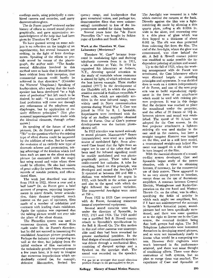
special construction, to provide maxi- mum volume and long playing, the cylinder record was oversize, and the horn and diaphragm considerably larger than those of home phonographs. Be- tween the reproducing stylus and the diaphragm was a mechanical power am- plifier, apparently using the principle of capstans used on shipboard. There was a continuously rotating amber cylinder and a hard rubber brake-shoe subtending about 130’ of arc. One end of the shoe was connected to the reproducing stylus in such a manner that an upward dis- placement of the stylus would increase the pressure between shoe and cylinder; and the other end of the shoe was con- nected through a slender rod to the dia- phragm, in such a way that the shoe movement resulting from increased fric- tion would give an upward push on the diaphragm.” One may well imagine that the adjustment of this device to give substantial gain without producing chat- tering must have tested the skill of the best of operators. Nevertheless, it must have worked, for the record indicates that the Edison talking-picture show ran for several months in Keith’s Colonial Theatre in New York, with much ac- claim, and was shown in other large cities of America and in other countries.
The arrangement for synchronizing was not in accordance with present prac- tices. The phonograph behind the screen determined the speed, being con- nected through a string belt to a syn- chronizing device at the projector. The belt pulleys were about 3 in. in diameter. The belt passed from the phonograph up over idler pulleys and overhead, back t m the booth. The synchronizing device applied a brake to the projector, and the brake-shoe pressure depended on the rel- ative phase of phonograph and projec- tor, increasing rapidly as the projector got ahead in phase. With an even force
Fig. 1. Mechanical power amplifier of Thomas A. Edison and Daniel Higham.
June 1955 Journal of the SMPTE Volume 64 291

( N o Model J 3 Sheeta-Sheet I
A. 0 . & C . A . BELL & S. T A I N T E R . TRANSMITTINO AND RECORDINO SOUNDS BY B A D I A N T ENEBBY.
No. 341.213. Patented Mav 4. 1886.-
0 n L i i b . 2. \\ “..-
ie 2rcr Sensitized 1 1 / Disk (in Box)
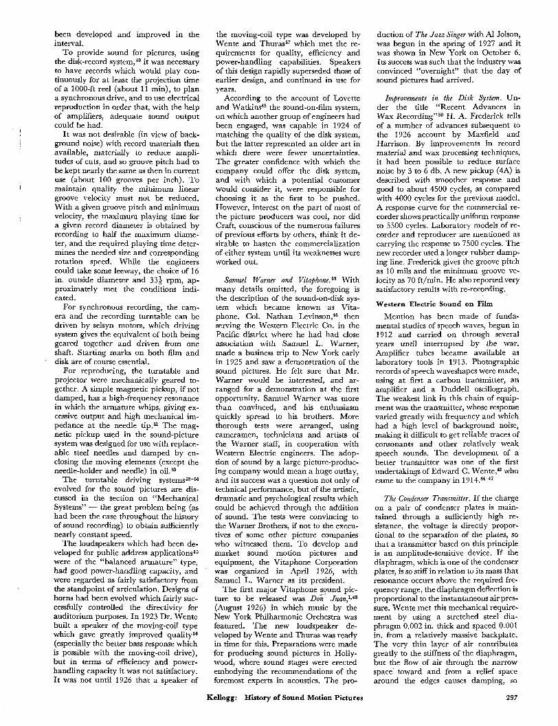
Fig. 2. Variable density recording system of A. G. Bell, C. A. Bell and Sumner Tainter, 1886.
on the projector crank, normal phase relation was maintained. The projec- tionist watched for synchronism and had a slight degree of control by turning the crank harder if the picture was behind or easing it off if it was ahead.
So far as I have learned, there were few further efforts (at least in the U.S.1 to provide sound for pictures by means of phonograph (mechanical) recording until the Warner Brothers’ Vitaphone system of 1926.
Photographic Sound Recording
A history of sound pictures necessarily includes the many efforts to record sound photographically, whether or not the ex- perimenters made any attempt to com- bine the sound with pictures, or were even interested in that application. Despite the obvious advantages, from the syn- chronized-sound standpoint, of a photo- graphic record of the sound on the same film with the picture, it does not appear that this.consideration was necessarily an important factor in directing experimen-
tation toward photographic recording, nor even that ultimate application to synchronous sound for motion pictures was (in many cases) a main objective. I t was rather that photographic recording represented a new medium, which seemed to offer promise of much superior results. A mechanical system seems in- herently crude where such delicacy is needed as in reproducing sound; in contrast to which recording by a beam of light would seem ideal. The experi- menters have all been conscious of the handicap imposed by the necessity of making ponderable mechanical parts vibrate at high frequency.
So we find that efforts to record sound photographically began before there were such things as motion pictures on strips of film. Before the invention of the telephone, Alexander Graham Bell, interested in aiding the deaf, had made photographic records of “manometric flames,” showing voice waves. His pat- ent, No. 235,199, filed in 1880, shows a system for transmitting speech over a
beam of modulated light, and uses a light-sensitive device (selenium cells) to detect the received fluctuations, thus anticipating the essential principle of the reproducing system which was used in many later experiments.
Blake. Prof. E. W. Blake of Brown University in 1878 made photographic recordsof speech sounds on a moving pho- tographic plate, using a vibrating mirror. 6,18
FrittS. U.S. Patent No. 1,203,190, filed in 1880 by Charles E. FriLts,S,6 discloses photographic soundtracks and a great variety of devices for recording and reproducing, but there does not appear to be evidence of much significant ex- perimental work.
Bell and Tainter. In the Smithsonian Museum in Washington, D.C., are a number of large glass disks carrying spiral sound tracks. These were made by a method described in U.S. Patent No. 341,213 (filed 1885) to Alexander Gra- ham Bell, Chichester A. Bell and Sumner Tainter. Light from a steady source was transmitted in a relatively narrow beam through a piece of stationary glass, and then further restricted by a slit where it reached the circular photographic plate. Just above the place where the light entered the stationary glass, a tiny jet of ink (or other light-absorbing liquid) was directed against the surface. The nozzle was attached to a “sounding board” (small plate) which picked up the sound vibrations. The jiggles of the nozzle caused waves in the stream of ink which flowed down over the surface, and these modulated the transmitted light.
Some years ago it became desirable, in connection with a patent suit, to demon- strate that the spiral track was really a soundtrack. Contact prints (on celluloid films) were made of several of the most promising looking of the glass plates, and a reproducing system arranged, giving the record the benefit of modern equip- ment in this respect. The approximate best speed was found by trial. (The original recording machine was hand- cranked). The photographic image had suffered from age and was very noisy, and the total recording lasted only a few seconds. But it was with some- thing of the thrill of an antiquarian that we listened to the voice from the past. “This is . . . . I a m . . . in the . . . labora- tory.” The date was given too ‘‘ . . . , eighteen eight- . . .?”
Others. Sponable’s historical paper mentions numerous other workers and their patents. Several of these modulated the light by means of a small mirror connected to a diaphragm so that vibra- tion caused rotation, thus anticipating features of equipment used by C. A. Hoxie in the work at General Electric Co. Of the developments which, although
292 June 1955 Journal of the SMPTE Volume 64

not leading to any commercial system, deserve special mention, I shall speak of several inventions or discoveries which laid foundations for later developments, and of the direct contributions to photo- graphic recording of Ruhmer, Lauste, de Forest, Reis and Tykociner.
Basic Inventions and Discoveries Selenium Cells. For many years, re-
production from photographic-sound rec- ords was made possible by the selenium cell. The photoconductive properties of selenium were discovered by Willoughby Smith in 1873, and a practical selenium cell was made by Werner Siemens in 1876.19 The response of a selenium cell to changes in illumination is sluggish, mak- ing it a very imperfect tool for sound re- production, whereas the photoemissive effect on which photocells depend is practically instantaneous, but the elec- trical output from a selenium cell is very much greater.
The Photocell. The first indication of photoemission was discovered by Hertz in 1887 and later studied by Hallwachs (1888), Stoletow (1890) and Elster and Geitel (1889 to 1913).19J0 Although by 1900 much had been learned, practical photocells did not become generally available till some years later, nor were they of help toward sound reproduction without electronic amplifiers.2!J2
Thermal Emission - The “Edison Efect.” Edison discovered in 1883 that a small current could flow through evacu- ated space in a lamp bulb, between a hot filament and a separate electrode. The Fleming “Valve,” invented in 1905, made use of this principle, played an im- portant part in early wireless telegraphy and was the forerunner of thermionic amplifiers.26
The Audion. The invention of the “Audion” by Lee de Forest in 1907 marked the beginning of the electronic era. As has been emphasized by many writers, it was the electronic amplifier which unlocked the door to progress and improvement in almost every phase of sound transmission, recording and re- production. However, amplifying tubes did not become generally available to experimenters for over a decade. The de Forest patent2? (acquired by the Telephone Company) was basic and un- challenged, but the vacuum techniques of some of the foremost laboratories of the countryN were needed to make of the audion a dependable and reasonably rugged tool. *
The Oscillograph. The oscillograph, consisting of a small mirror mounted on a pair of conductors, close together, in a
* Much higher vacuum than de Forest had been able to obtain was necessary. This was inde- pendently accomplished by I. Langmuir of General Electric Co. and H. D. Arnold of Western Electric C0.24
strong magnetic field, was invented by Blonde1 in 1891 and improved in 1893 by Duddell, who put it into practically the form still used. I t has played a vital part in photographic sound recording.
Magnetic Recording. The invention by Poulsen of Copenhagen in 1900 of re- cording magnetically on a steel wire laid the foundation for modern tape record- ing, which has almost revolutionized methods of making original record- ings.27
Auditorium Acoustics. The modern science of room acoustics and acoustic treatment dates from the work of Prof. Wallace C. Sabine of Harvard in the years 1895 to 1900.28 With little other equipment than a whistle, a stop watch and brains, he worked out the acoustic principles on which successful sound re- cording and reproduction so largely depend.
Gas-Filled Incandescent Lamps. Beyond a certain point, optical-recording systems cannot give increased exposure by in- creasing the size of the source, but only by increasing the intensity (candles per square centimeter), which means higher temperature. Early incandescent lamps were well exhausted because all gas re- sults in loss of heat by convection and hence lowered efficiency. In 1911-13 Irving Langmuir of General Electric Co. studied the effects of inert gas not only on heat loss, but also on the rate of evapora- tion of tungsten from the filament surface, which is the factor which determines permissible operating temperature. He showed that such gases as nitrogen, or better yet argon (the heavier the better), at pressures well up toward atmospheric or even higher, could with suitably formed filaments so retard the evaporation of tungsten that the higher permissible temperature much more than compen- sated for the added heat convection, thus giving several-fold increase in effi- cency as well as whiter light. With the gas, the evaporated tungsten is carried to the top of the bulb instead of blacken- ing the sides, in the optical path.29
Magnetic Materials. The development of several alloys of iron, nickel and cobalt having extraordinary magnetic proper- ties is reported by H. D. Arnold and G. W. Elmen in the Bell System Technical Journal of July 1923, and by Elmen in the January 1929 and July 1929 issues. The extremely high permeability and low hysteresis of Permalloy have .made it possible to greatly reduce distortion in transformers and in many electrome- chanical devices, and to provide more successful magnetic shielding than would otherwise be possible. In another alloy which has been called Perminvar, con- stancy of permeability and low hysteresis (making for low distortion) have been carried still farther. Another alloy named Permendur can carry very high flux den-
Kellogg: History of Sound Motion Pictures
sities before saturation, making it pos- sible to produce intense fields which make for sensitivity and damping in devices of the moving conductor type.
Important for the reduction of cost and weight of magnetic devices was the discovery by the Japanese physicist T. Mishima of the properties of certain alu- minum-nickel-cobalt alloys for perma- nent magnets,3O and subsequent improve- ments.
Improvements in Vacuum Tubes and Phototubes. In any list of the advances which contributed in an important way to the technical attainments in modern sound reproduction, several improve- ments in amplifier tubes deserve an im- portant place. Among these are :
(1) The Wehneldt (oxide coated] cathode and other low-temperature emitters, which in turn made indirectly heated unipotential cathodes possible.
(2) The screen-grid tube. (3) The pentode. (4) Remote cutoff or exponential
(5) The caesium phototube with its
(6) The gas-filled phototube with its
tubes, and other variable gain tubes.
high sensitivity to infrared light.
increased output.
Early Work on Sound on Motion-Picture Film
Ruhmer. Ernst Ruhmer in Berlin5~6~31 in 1901 began publication of the results of his work on photographic sound record- ing, which extended over a period of about twelve years. As sources of modu- lated light he superimposed voice currents on the continuous currents in electric arcs. He used considerably higher film speeds than those used for pictures. Sponable reported (ref. 6, p. 278) that some of Riihmer’s Photographophon films were brought to this country by the Fox Film Corp., and that the articula- tion was clear; also, this reference shows a sample of Ruhmer’s soundtrack. A variable-area track by Rtihmer is shown in the Theisen history (ref. 5, p. 421), the Scient8c American of 19Ol3l being cited as reference. Presumably Ruhmer experi- mented with both systems.
Lauste. This Society has taken special note of the work of Eugene Augustine Lauste, in a 1931 report of the Historical Committee,32 in a paper by Merritt C r a w f ~ r d ~ ~ and in placing his name on the Society’s Honor Roll. The young Frenchman joined the staff of Thomas A. Edison in 1887, where he did construc- tion and experimental work till 1892. For two years he worked on another project and then, in association with Maj. Latham, developed a projector which was the first to incorporate the extra sprocket and free loops with the intermittent. Lauste’s interest in photo- graphic sound recording was first aroused when in 1888 he found in an old copy of the Scientijc American (May 21,
293

1881) an account of Dr. Bell’s experiment in transmitting sound over a modulated light-beam, and converting to electrical modulation by means of a selenium cell. This suggested the thought of recording the sound photographically on the same strip with the picture. I t was not till about 1900 that he began to find oppor- tunity to work on this project. He worked for several years in the United States and then went to England where he pursued his experiments. A British patent (No. 18,057, filed in 1906) shows a well thought-out system. Lauste re- ceived some financial backing in 1908 from the manager of the London Cine- matograph Co.
To modulate the recording light, Lauste used rocking mirrors and what have been described as “grate-type light-valves.” The mirror system was too sensitive to camera vibrations, and the grate-type valves which he was able to build had too much inertia. In 1910 he began working with modulators of the string galvanometer type, with ex- cellent results. The historical account by Theisen,6 shows photographs of some of Lauste’s apparatus. He spent some time with Ernst Ruhmer in Berlin, a stimulating and profitable association. He visited America in 191 1 and as part of his demonstration made what was prob- ably the first actual sound-on-film motion picture made in the U.S. A neces- sary return to England, shortage of capi- tal, and the war, halted Lauste’s sound- picture researches. In his paper on Lauste, Crawford expresses the thought that had it not been for this unfortunate interruption, plus very limited resources, and had electronic amplifiers been avail- able to Lauste, commercialization of sound pictures might well have gotten started a decade before it actually did.
E. E. Ries filed application in 1913 for a patent (No. 1,473,976, issued in 1923) in which broad claims were allowed on the essentials of a single-film system. The patent became the basis of later litigation.B
Tykociner. In 1918 and following, Prof. J. T. Tykociner of the University of Illinois carried on experiments and de- veloped a system. This work was de- scribed before the American Institute of Electrical Engineers and in the SMPE Transactions.34 After pointing out that three new tools had in comparatively recent times become available for the solution of the sound-picture problem, (namely, high-frequency currents, pho- toelectricity, and thermionic amplifiers), Prof. Tykociner gives a broad discussion of requirements and possible arrange- ments. As a source of modulated light he used for the most part a mercury arc with either modulated continuous cur- rent or modulated high-frequency cur- rent, and for reproduction a Kunz (cathode of potassium on silver) photo-
cell. The light from the mercury arc is particularly potent photographically, but is sluggish in following the input modula- tion, which results in some loss of the higher audio frequencies.
Foreign Developments Which Led to Commercial Systems
Tri-Ergon (meaning “the work of three”). Josef Engl, Joseph Massole and Hans Vogt, in Germany, began in 1918 the development of a system of sound pictures which later was commercial- ized under the name Tonbild Syndicat AG (abbreviated to T ~ b i s ) . ~ J ~ They used a modulated glow discharge for recording, and a photocell for repro- ducing. Of chief concern in this country were the Tri-Ergon patents,36 in which numerous claims allowed by the U.S. Patent Office were so broad that had their validity been sustained they would have almost swamped the industry. In particular, one patent (1,713,726) which claimed the use of a flywheel on the shaft of a roller or sprocket which carries the film past the translation point, to take out speed variations, was the basis of prolonged litigation, being finally declared invalid by the U.S. Supreme Court (l935).ll4 But in the meantime the efforts to avoid what were thought to be dangerous in- fringements of the Tri-Ergon flywheel claims, had for seven years steered the course of mechanical designs on the part of the major equipment manu- facturers into inferior or more com- plicated constructions. (See section on Mechanical Systems.)
In Germany the Tri-Ergon patents controlled the situation. The large picture producing companies, U.F.A. and Klangfilm (a subsidiary of Siemens & Halske and A.E.G.), took licenses under the Tri-Ergon patents. A brief account of the patent negotiations and agree- ments in this company and in Germany will be found in the Sponable paper.6
Peterson and Poulsen in Denmark de- veloped a system (1923) which was com- mercialized in Germany under the name Tonfilm.6 They used an oscillo- graph as the recording light modulator (giving a variable-area soundtrack), and a selenium cell for reproduction. (One of the Tri-Ergon U.S. patents35 claimed the use of a photocell for this purpose, and it is likely that a German patent accounts for the use of a se- lenium cell by Poulsen and Peterson.) This system was used by Gaumont in France and by British Acoustic Films, Ltd.
The de Forest Phonofilm
Dr. de Forest tells the story of this work in the 1923 Transactions.36 The ac- count is particularly interesting because he tells much of his viewpoint as he started, and then, after describing the system which he had evolved, gives his
reflections on the applications and future of sound motion pictures.
The man whose invention gave us amplifiers in which the heaviest object that had to be moved was an electron, surely had a right to wish to do away with moving mechanical parts in micro- phones, light-modulators and loud- speakers. For microphones he experi- mented with the conductivity of gas flames and of open arcs as affected by sound waves, and with fine platinum wires heated to a dull red by a direct current and subjected to the cooling effect of the air vibrations superimposed on a slight continuous air movement. The changes in resistance of the wires with variations of temperature gave rise to telephonic currents.
For light modulators he tried “the speaking flame” (probably the “mano- metric” flame of Konig) and a tiny incandescent lamp, carrying voice cur- rents superimposed on direct current. The lamp was designed to have very rapid filament cooling (partly by using a short filament, so that heat conduction to the lead-in wires would be high). On listening to these sources by means of a photocell and amplifier, de Forest was convinced that they gave excep- tional quality (even compared with the condenser microphone), but they proved entirely inadequate for making a useful soundtrack giving very small per- centage of modulation and probably also underexposure. Finally a successful source of modulated light for recording was found in a gas-filled tube excited by modulated high-frequency currents from a 5- to 10-w radio telephone trans- mitter. This was named the “Photion.” A slit, 1; to 2 mils wide and 3/32 in. long, adjacent to the film, was used to restrict the size of the exposing beam.
A similar slit was used in reproduction. Both potassium photocells and Case Thalofide3’*” cells were used in repro- ducing equipment, the greater sensi- tivity obtainable with the Thalofide cell being a consideration offsetting the faster response of the photocell. The design and construction of amplifiers using his Audion were of course very familiar to de Forest.
Lament is expressed that loudspeakers depending on some principles other than diaphragms and horns were not to be had, but after some discourage- ments with “talking arcs” and sound radiators on the thermophone prin- ciple, the commercially available horn and diaphragm speakers were accepted as the only solution at the time.*
Practical models of recording and re- producing equipment were built, and re- * I t is of interest that in the early part of our investigation which led to the direct radiator dynamic speaker (Trans. AIEE, 1925, p. 461) Chester W. Rice and I tried talking arcs and thermophones, and also a corona discharge device - all of which avoid mechanical moving parts - but none of these appeared pr0mising.a
294 June 1955 Journal of the SMPTE Volume 64
I
cordings made, using principally a com- bined camera and recorder, and many demonstrations given.
The de Forest p a p e 9 reviewed earlier history of efforts to record sound photo- graphically, and gave appreciative ac- knowledgment of the help that had been given by Theodore W. Case.37
To have guessed wrong on some sub- ject is no reflection on the insight of an experimenter, but several instances are striking, in the light of later develop- ments. Speaking of the efforts to pro- vide sound by means of the phono- graph, the author said: “The funda- mental difficulties involved in this method were so basic that it should have been evident from their inception, that commercial success could hardly be achieved in that direction.” (Consider the Warned Vitaphone.) Speaking of loudspeakers, after saying that the loud- speaker has been developed “to a high state of perfection” but left much to be desired, he said: “I am convinced that final perfection will come not through any refinements of the telephone and diaphragm, but by application of en- tirely different principles.” (Yet phe- nomenal improvements were made with the identical elements, through refine- ments.)
In speaking of the future of sound pictures, Dr. de Forest gave a definite “No” to the question whether the existing type of silent drama could be improved by the addition of voice. But he foresaw the evolution of an entirely new type of dramatic scheme and presentation, tak- ing advantage of the freedom which had been such an asset to the silent moving picture (as contrasted with the stage) but using sound and voice where these could be effective. He also had visions of great utility for travel films, newsreels, records of notable persons, and educa- tional films.
The work just described was done from 1918 to 1922. About a year and a half laterse Dr. de Forest gave a brief account of progress, reporting improve- ments in many details, better articula- tion, thirty theaters equipped, much interest on the part of operators, films made of a number of celebrities and contracts with leading chain exhibitors. Again the opinion was expressed that the talking picture would not ever take the place of the silent drama.
The Phonofilm system was used in numerous theaters, with sound films made under Dr. de Forest’s direction; but he did not succeed in interesting the established American picture producers. Perhaps the industry was prospering too well at the time, but judging from the initial coolness of film executives to the technically greatly improved systems a few years later, it is easy to imagine that numerous imperfections which un- doubtedly existed (as, for example, defective film-motion, limited fre-
quency range, and loudspeakers that gave unnatural voices, and perhaps too, demonstration films that were uninter- esting) contributed to loss of the im- pressiveness needed for doing business.
Several years later the “de Forest Phonofilm Co.” was bought by Schles- inger of London and South Africa.
Work at the Theodore W. Case Laboratory ( Movietone)6
Theodore W. Cases7 became inter- ested in modulating light and deriving telephonic currents from it in 1911, while a student at Yale. In 1914 he organized his laboratory at Auburn, N.Y., devoting special attention to the study of materials whose resistance is altered by light, of which selenium was the best known example. These studies resulted (1917) in the development of the Thalofide cell, in which the photo- sensitive material is thallium oxysulfide.40 These cells, which are especially sen- sitive in the near infrared range, were widely used in Navy communication systems during World War I. Case was joined in 1916 by E. I. Sponable. Experiments were continued with the help of an Audion amplifier obtained from de Forest. One of Case’s postwar developments was the barium photo- electric cell.
In 1922 attention was turned seriously to sound pictures. Manometric* flames (oxyacetylene) were tried as a possible source of modulated light. Soon after- ward Case found that the light from an argon arc in one of the tubes that had been used for infrared signalling could be readily modulated and was photo- graphically potent. These tubes had oxide-coated hot cathodes. A tube for recording, based on this principle, was developed and named the Ae~-light.~*~l It operated at between 200 and 400 v. Helium was substituted for argon in 1922, with benefit to the actinic power and also to the speed with which the light followed the current variation. The commercial Aeo-lights were rated at 350 v.
From 1922 to 1925 Case cooperated with de Forest, furnishing numerous items of experimental equipment.
Several sound cameras were built under the direction of Sponable, in 1922, 1923 and 1924. The 1924 model was a modified Bell & Howell camera rebuilt to Sponable’s specifications by the Bell & Howell Co. The film motion in this and other cameras was unaccept- able until they had been reworked for greater mechanical precision. In the final designs of sound camera the sprocket was driven through a mechanical filter, consisting of damped springs and a flywheel on the sprocket shaft. The sound was recorded on the sprocket.
* A gas jet so arranged that sound vibrations produce changes in the gas supplied to the jet.
Kellogg: History of Sound Motion Pictures
The Aeo-light was mounted in a tube which entered the camera at the back. Directly against the film was a light- restricting slit made by silvering a thin quartz plate, ruling a slit 0.0006 in. wide in the silver, and cementing over it a thin piece of glass which was then lapped to a thickness of about 0.001 in. The slit was thus protected from collecting dirt from the film. The end of the Aeo-light, where the glow was concentrated, was close behind the slit. A Bell & Howell contact printer was modified to make possible the in- dependent printing of picture and sound.
Up to the fall of 1925, when the work- ing arrangement with de Forest was terminated, the Case laboratory efforts were directed largely to recording principles and apparatus. It was decided then to work on a system independently of de Forest, and one of the next proj- ects was to build reproducing equip- ment in the form of an attachment which could be used with existing pic- ture projectors. I t was in this design that the decision was reached to place the soundhead under the projector, and the offset of 20 frames or 144 in. between picture and sound was estab- lished. The speed of 90 ft/min was adopted for the Case system. In the first projector attachment a light-re- stricting slit was used similar to the one used in the camera, but later a straight tungsten filament was imaged on the film, and in a still later model, a concentrated straight-axis helical fila- ment was imaged on a slit which was in turn imaged on the film.
With the essential elements of a sound- on-film system developed, Case and Sponable began study of the patent situation, with a view to obtaining licenses, if necessary, for the commercial use of their system. There appeared to be no very strong patents to interfere, except those on the use of thermionic amplifiers. A contract between General Electric, Westinghouse and Radio-Cor- poration on the one hand and Western Electric Co. on the other, was in effect, specifying the fields of activity in which each might use amplifiers, but, if I have not misinterpreted the account in Sponable’s historical paper, sound- pictures had not been specifically men- tioned, and there was some question as to the right to license use in the Case system, the eventual decision being that both groups had rights. The Bell Telephone Laboratories were interested themselves in developing sound pictures, and so were not immediately ready to license what would be a competing sys- tem. However their engineers were much interested in the performance attained, and there was some thought of combining efforts. There were dem- onstrations of both systems, but no plan to merge them was reached. The experience of Case and Sponable at
295

General Electric Co. was rather similar. In 1926 demonstrations were made to
representatives of the Fox Film Corp., who became greatly interested, and finally to William Fox. After thorough testing on their own premises, the Fox Film Corp. purchased rights to the Case developments (July 23, 1926), leaving the question of amplifier rights to be worked out later. The Fox-Case Corp. was organized to exploit the system, which was given the name Movietone. Courtland Smith, who had been with the Fox Film Corp. and had been instru- mental in bringing about the purchase, was made president of the Fox-Case Corp. The Movietone News service was established.
Sponable left the Case organization to give his services to the new company, one of the first of his activities being the de- sign of recording studios in New York and later in Hollywood. In 1927 he de- veloped a screen which transmitted sound freely, permitting loudspeakers to be located directly behind the picture. The first public showing of Movietone re- cordings was in January 1927.
The Fox-Case Corp. obtained license to use amplifiers, first in 1926 through the Western Electric Co. and the Vitaphone Corp., and the next year revised con- tracts were made with Electrical Re- search Products, Inc. (ERPI), which was formed in January 1927 to handle the sound-picture business for the Western Electric and Telephone companies.
In the Movietone reproducing system, Western Electric amplifiers and loud- speakers were used. The years 1928 and 1929 were marked by rapid expansion in facilities and personnel, successful show- ings and stepped-up schedules of news- reel releases. In March 1929 the making of silent pictures by Fox was discon- tinued. Six months later the Fox and Hearst newsreel services were united.
The British Movietone News was or- ganized in 1929. In 1930 William Fox sold his interests in Fox Film and Fox Theatres.
As the Fox Film Corp. was already an ERPI licensee, and therefore had rights to use other Western Electric develop- ments, the Western Electric light valve was adopted for the Movietone service (as well as for Fox studio recording), dis- placing the Aeo-light.
Work at Western Electric Co. and Bell Telephone Laboratories
The Western Electric Co. brought to a commercial stage almost simultaneously a sound motion-picture system based on disk records, and one based on sound on film. Various developments which laid the foundations for these systems had been taking place through a number of years. The citation of the life and work of Edward B. Craft in this Journal4 indi- cates that his interest and enthusiasm were in large measure responsible for the
undertaking of a full-scale project for de- veloping systems of sound for motion pictures. Craft was assistant chief engi- neer of the Western Electric Co. from 1918 to 1922, when he became chief en- gineer. With the transfer in 1924 of re- search activities to the newly organized Bell Telephone Laboratories, Craft was made executive vice-president, and con- tinued to guide acti~ities.4~
Whether or not there was a definite policy of not putting all of the eggs in one basket, work on both systems was stepped up at about the same time (1922) and pushed with equal vigor.
The two systems had identical re- quirements with respect to many ele- ments, but, in particular, microphones, amplifiers and loudspeakers. The West- ern Electric Co. had acquired rights to de Forest’s Audion in 1913 and made great improvements in it during the next few years, building up wide experience in its applications and circuitry.
Second only to electronic amplifiers in importance for the development of high- quality recording and reproducing sys- tems was a microphone of uniform re- sponse and with low distortion. With amplifiers available Dr. E. C. Wente43 was able largely to ignore the question of output level, and to develop by 1916 a microphone of the condenser type, hav- ing extraordinarily high fidelity and free- dom from distortion and n0ise.4~~7
In the loudspeaker field, the company had had considerable experience and had developed units for public address work. The public address installations had af- forded experience with auditoriums and requirements for intelligibility, while experience in acoustics for sound pickup had been gained in radio broadcasting.
With respect to the recording itself and reproduction, I shall separate the two stories of the disk and photographic systems.
The Disk System
In 1946 there was published a history of sound recording in the laboratories of the Western Electric c0.4~ Since the transmission of speech was the main business of the Telephone Co., a pro- gram of studying every aspect of speech waves was initiated about 1912, and as part of this project, efforts were directed to recording the sound. The interest soon spread to include music. In connec- tion with work with disk records, Cran- dall and Kranz built an electromagnetic reproducer in 1913. In 1915 H. D. Arnold suggested that the improvement of disk recording be undertaken, using the then available electrical equipment (which included amplifiers). By this time the electrical reproducer had been improved.
The war interrupted these projects, but they were resumed soon after its close. A group under J. P. Maxfield undertook the improvement of wax re-
cording and the phonograph. The story of this development was told in 1926 to the American Institute of Electrical En- gineers.49 The recording system made use of a magnetically driven cutter so designed that with constant current in- put, the vibratory velocity of the cutting stylus was substantially constant from about 200 to 5000 cycles, while from 50 to 200 cycles the amplitude was con- stant, a characteristic practically neces- sary to avoid overcutting by the low notes. Two features of the design were of special interest: (1) the separation of the total mass that must be driven into three parts (armature, stylus-bar and coupling disk), connected together through por- tions of shaft whose torsional flexibility was carefully calculated to make of the structure a mechanical low-pass filter of calculable mechanical impedance; and (2) a mechanical resistance consisting of a thick-walled rubber tube (which may be thought of as practically a rod of soft rubber) subjected at one end through the coupling disk to torsional vibrations. The propagation of torsional waves in such a soft rubber rod is so slow that in a length of about 6 in. there would be many wavelengths for all but the lowest frequencies.
Vibrations imparted to the rubber reach the far end very much attenuated, are reflected, and propagated back to- ward the start, but are of neligible magni- tude when they reach it. Under such con- ditions the rubber line acts as a nearly pure mechanical resistance to load the filter, and, if properly matched to the fil- ter impedance, results in practically com- plete (and therefore uniform) transmis- sion through the filter structure, through- out the frequency band below the filter cutoff. The features just described are, I believe, the inventions of H. C. Harrison. The great improvement in records which electrical recording brought, is well known to all of us.
Without a better reproducing system than the phonographs of the types in use about 1920, the improvements in the records would have been largely lost, so there was developed a greatly improved (nonelectrical) phonograph called the Orthophonic (also largely the outcome of H. C. Harrison’s approach to the prob- lem). However this part of the program had no direct bearing on the talking- picture project. In early 1925 the Colum- bia and Victor Companies took licenses from Western Electric Co. to use the re- cording methods and apparatus, and to build phonographs of the Orthophonic type.
Sou&-on-Disk Synchronized With Pic- tures. Little time was lost in trying and demonstrating synchronized sound and pictures using the new electrically re- corded disks. Craft arranged for a dem- onstration at Yale University in 1922 and another in February 1924, the equipment and many details of the system having
296 June 1955 Journal of the SMPTE Volume 64
I
been developed and improved in the interval.
To provide sound for pictures, using the disk-record system,5o it was necessary to have records which would play con- tinuously for a t least the projection time of a 1000-ft reel (about 11 min), to plan a synchronous drive, and to use electrical reproduction in order that, with the help of amplifiers, adequate sound output could be had.
It was not desirable (in view of back- ground noise) with record materials then available, materially to reduce ampli- tudes of cuts, and so groove pitch had to be kept nearly the same as then in current use (about 100 grooves per inch). To maintain quality the minimum linear groove velocity must not be reduced. With a given groove pitch and minimum velocity, the maximum playing time for a given record diameter is obtained by recording to half the maximum diame- ter, and the required playing time deter- mines the needed size and corresponding rotation speed. While the engineers could take some leeway, the choice of 16 in. outside diameter and 334 rpm, ap- proximately met the conditions indi- cated.
For synchronous recording, the cam- era and the recording turntable can be driven by selsyn motors, which driving system gives the equivalent of both being geared together and driven from one shaft. Starting marks on both film and disk are of course essential.
For reproducing, the turntable and projector were mechanically geared to- gether. A simple magnetic pickup, if not damped, has a high-frequency resonance in which the armature whips, giving ex- cessive output and high mechanical im- pedance a t the needle tip.51 The mag- netic pickup used in the sound-picture system was designed for use with replace- able steel needles and damped by en- closing the moving elements (except the needle-holder and needle) in oil.52
The turntable driving systems52-54 evolved for the sound pictures are dis- cussed in the section on “Mechanical Systems” - the great problem being (as had been the case throughout the history of sound recording) to obtain sufficiently nearly constant speed.
The loudspeakers which had been de- veloped for public address applications55 were of the “balanced armature” type, had good power-handling capacity, and were regarded as fairly satisfactory from the standpoint of articulation. Designs of horns had been evolved which fairly suc- cessfully controlled the directivity for auditorium purposes. In 1923 Dr. Wente built a speaker of the moving-coil type which gave greatly improved quality56 (especially the better bass response which is possible with the moving-coil drive), but in terms of efficiency and power- handling capacity it was not satisfactory. I t was not until 1926 that a speaker of
the moving-coil type was developed by Wente and Thurass7 which met the re- quirements for quality, efficiency and power-handling capabilities. Speakers of this design rapidly superseded those of earlier design, and continued in use for years.
According to the account of Lovette and W a t k i n ~ ~ ~ the sound-on-film system, on which another group of engineers had been engaged, was capable in 1924 of matching the quality of the disk system, but the latter represented an older art in which there were fewer uncertainties. The greater confidence with which the company could offer the disk system, and with which a potential customer would consider it, were responsible for choosing it as the first to be pushed. However, interest on the part of most of the picture producers was cool, nor did Craft, conscious of the numerous failures of previous efforts by others, think it de- sirable to hasten the commercialization of either system until its weaknesses were worked out.
Samuel Warner and Vitafihone.58 With many details omitted, the foregoing is the description of the sound-on-disk sys- tem which became known as Vita- phone. Col. Nathan L e v i n ~ o n , ~ ~ then serving the Western Electric Co. in the Pacific district where he had had close association with Samuel L. Warner, made a business trip to New York early in 1925 and saw- a demonstration of the sound pictures. He felt sure that Mr. Warner would be interested, and ar- ranged for a demonstration at the first opportunity. Samuel Warner was more than convinced, and his enthusiasm quickly spread to his brothers. More thorough tests were arranged, using cameramen, technicians and artists of the Warner staff, in cooperation with Western Electric engineers. The adop- tion of sound by a large picture-produc- ing company would mean a huge outlay, and its success was a question not only of technical performance, but of the artistic, dramatic and psychological results which could be achieved through the addition of sound. The tests were convincing to the Warner Brothers, if not to the execu- tives of some other picture companies who witnessed them. To develop and market sound motion pictures and equipment, the Vitaphone Corporation was organized in April 1926, with Samuel L. Warner as its president.
The first major Vitaphone sound pic- ture to be released was Don Juan,1@ (August 1926) in which music by the New York Philharmonic Orchestra was featured. The new loudspeaker de- veloped by Wente and Thuras was ready in time for this. Preparations were made for producing sound pictures in Holly- wood, where sound stages were erected embodying the recommendations of the foremost experts in acoustics. The pro-
Kellogg: History of Sound Motion Pictures
duction of The Jazz Singer with A1 Jolson, was begun in the spring of 1927 and it was shown in New York on October 6. Its success was such that the industry was convinced “overnight” that the day of sound pictures had arrived.
Improvements in the Disk System. Un- der the title “Recent Advances in Wax Recording”5o H. A. Frederick tells of a number of advances subsequent to the 1926 account by Maxfield and Harrison. By improvements in record material and wax processing techniques. it had been possible to reduce surface noise by 3 to 6 db. A new pickup (4A) is described with smoother response and good to about 4500 cycles, as compared with 4000 cycles for the previous model. A response curve for the commercial re- corder shows practically uniform response to 5500 cycles. Laboratory models of re- corder and reproducer are mentioned as carrying the response to 7500 cycles. The new recorder used a longer rubber damp- ing line. Frederick gives the groove pitch as 10 mils and the minimum groove ve- locity as 70 ft/min. He also reported very satisfactory results with re-recording.
Western Electric Sound on Film Mention has been made of funda-
mental studies of speech waves, begun in 1912 and carried on through several years until interrupted by the war. Amplifier tubes became available as laboratory tools in 1913. Photographic records of speech waveshapes were made, using a t first a carbon transmitter, an amplifier and a Duddell oscillograph. The weakest link in this chain of equip- ment was the transmitter, whose response varied greatly with frequency and which had a high level of background noise, making it difficult to get reliable traces of consonants and other relatively weak speech sounds. The development of a better transmitter was one of the first undertakings of Edward C. Wente,43 who came to the company in 1914.4-47
The Condenser Transmitter. If the charge on a pair of condenser plates is main- tained through a sufficiently high re- sistance, the voltage is directly propor- tional to the separation of the plates, SO
that a transmitter based on this principle is an amplitude-sensitive device. If the diaphragm, which is one of the condenser plates, is so stiff in relation to its mass that resonance occurs above the required fre- quency range, the diaphragm deflection is proportional to the instantaneous air pres- sure. Wente met this mechanical require- ment by using a stretched steel dia- phragm 0.002 in. thick and spaced 0.001 in. from a relatively massive backplate. The very thin layer of air contributes greatly to the stiffness of the diaphragm, but the flow of air through the narrow space toward and from a relief space around the edges causes damping, so
297

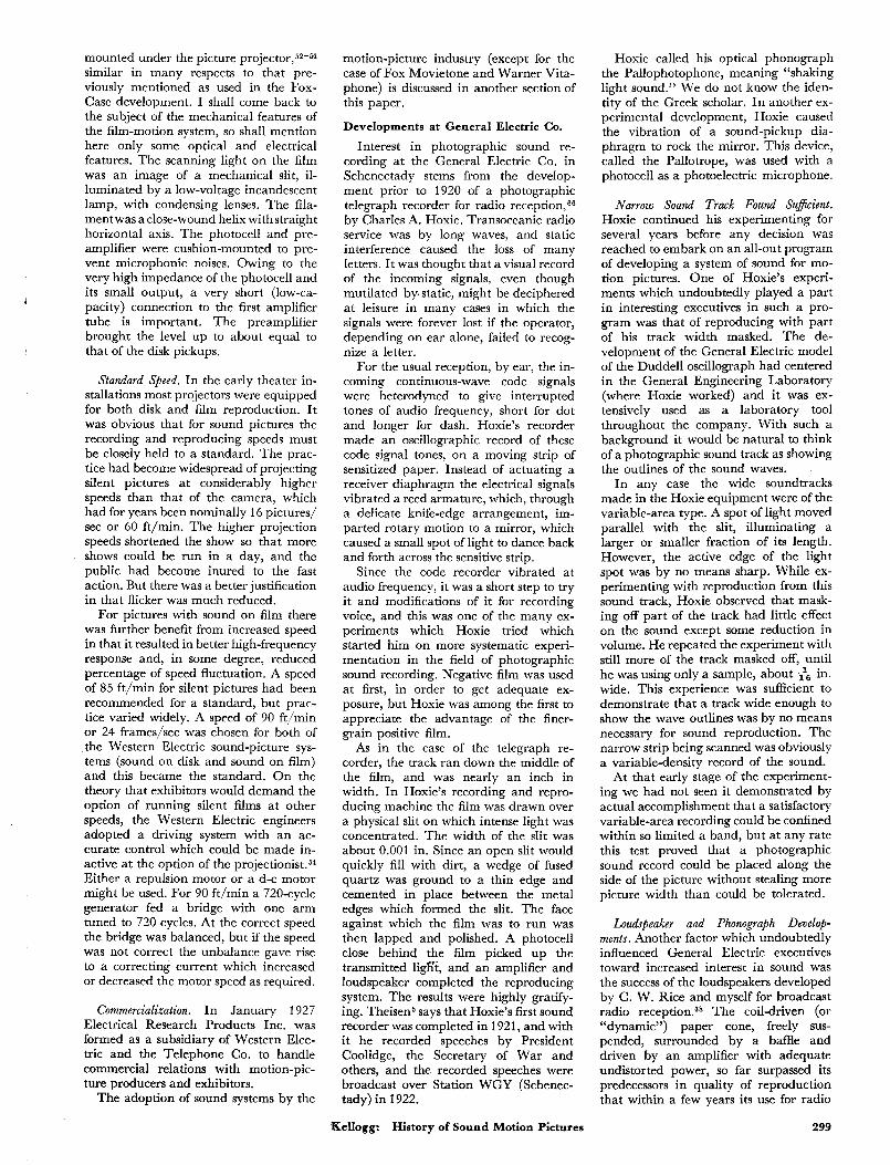
Fig. 3. Light-valve ribbon and pole piece arrangement; section at right
angles to ribbons.
that a nearly flat (uniform) response was obtained up to about 15,000 cycles.
Wente left the company in 1916 for graduate study and returned in 1918. In the meantime Dr. I. B. Crandall had made a theoretical analysis of the air- film damping, and improved the instru- ment by means of grooves of appropriate size and shape in the b a ~ k p l a t e . ~ ~ For measurement purposes it was essential to calibrate the condenser transmitter, and Wente accomplished this by working out the theory of the thermophone, which enabled him to make a reliable pressure ~a l ib ra t ion .~~ Free field calibrations were made later, using a Rayleigh disk as reference. In a later design,47 which was used commercially for sound recording, the sensitivity was greatly increased, in part by use of aluminum alloy 0.001 in. thick instead of 0.002 in. steel for the diaphragm, and in part by not carrying the response as far into the high-fre- quency range. (In 1931 W. C . Jones published a pressure calibration curve for a 8394 transmitter which showed a rapid drop above about 7000 ~ycles.4~) The condenser tramsmitter is rated as a a very insensitive device, but it is of in- terest that a diaphragm deflection of a millionth of an inch will give a fifth of a volt, the gradient in the space between electrodes being 200 v per mil. I t is the ex- treme stiffness of the diaphragm which makes the sensitivity low.
Photograghic Recordings. The condenser transmitter with amplifier gave better waveshape traces, but the narrow mirror of the bifilar (or Duddell) oscillograph causes diffraction effects which make the light-spot at the film blurred or fuzzy. Prof. A. C. Hardy showed5g that this trouble could be largely eliminated by radical changes in the optical system in which the oscillograph vibrator is used, but his analysis was not published until 1927 (in time to be of much help in the General Electric recording develop- ments, but the Western Electric experi- ments with the oscillograph were before 1920).
An article in a British Journal (1920) came to Wente’s attention, describing experiments of Prof. A. 0. Rankine in transmission of sound over a beam of light. The light modulator, in which a rocking mirror caused an image of one
grating formed on another grating to move transversely to the bars, appeared well adapted to making photographic records of the variable-density type. While a variable-density record would not give as much information to the eye as a variable-area record, it could be analyzed by instruments of the micro- densitometer type. The faithfulness of the recording could be checked by playing it back. (The previous oscillographic re- cordings had not been designed for playing back.)
Some of the recordings were played in May 1922 for Craft and others. A few months later apparatus-development en- gineers were requested to construct an electrically interlocking driving system for camera and recorder. Further demon- strations were given in December 1922. In these recordings the principle was recognized, that for linear relations be- tween exposing light and print transmis- sion, the product of positive and negative “gammas” should be unity.61,62
Light Valve. The grating type of modu- lator had several drawbacks, one of which was diffraction by the grating. Because of these difficulties, Wente in January 1923 proposed using a two- string light val~e.m-‘j~*~ Such a valve was ready for test a month later. The tension on the ribbons was adjusted to bring their resonance to 6500 cycles. Condens- ing lenses imaged the light source on the slit between the ribbons, and an objec- tive lense imaged the valve slit on the film.
Results with the light valve were definitely better than with the previous modulators, and arrangements were made for tests on a larger scale. A record- ing studio was set up in 1923 and sound pictures made for demonstration pur- poses.
In the latter part of 1922 and subse- quently, much of the study of film emul- sions, exposures and developments was carried on by Dr. Donald MacKenzie. He showed that by running the lamp a t slightly over-voltage, it was possible ade- quately to expose positive film, which thereafter was the standard sound-re- cording stock. The relatively fine grain of the positive stock was of great benefit from the standpoint of resolution and low background noise.
In 1928 MacKenzie described the light-valve model in use a t the time, and recording and processing practice (ex- posure ranges and developments) as worked out at the Bell Telephone Labo- ratories.‘j4 The valve is mounted with the slit between ribbons horizontal - so that its image on the film is transverse to the film. The ribbons are in a strong magnetic field and currents in the two are in opposite directions, so that they are deflected (edgewise) to increase or de- crease their separation depending on the direction of the current. The width of the slit with no current in the ribbon was 0.002 in., and it was masked to a length of about 0.2 in. I t was imaged on the film with a 2 : 1 reduction. With the slit width 0.002 in., the light could be modulated 100% by a vibration of each ribbon of 0.001 in. amplitude. Since the ribbon need be only slightly wider than its double amplitude, thick enough to be opaque, reasonably easy to handle and long enough between supports to make the deflection substantially uniform throughout the length of the slit, it can be extremely light and readily put under enough tension to place its mechanical resonance above the required audio range. Rather than attempting to control the resonance by damping beyond that obtainable electromagnetically, an elec- trical low-pass filter was used in the in- put, to prevent the passage of any im- pulses of high enough frequency to ex- cite the resonance. However the cutoff was not too far below the frequency of resonance to permit a considerable rise in amplitude just before cutoff, the maxi- mum being at about 7000 cycles. This rise was regarded as advantageous in that it compensated for loss of high-frequency response due to image spread in the film. For monitoring, a photocell behind the film picked up some of the light which went through the film.
The subject of sensitometry for sound- tracks of the variable-density type also received attention from many other writers for a number of years after the advent of photographic sound.
In the matter of the frequency range attained in the early light-valve record- ings, MacKenzie shows an overall (light- valve input to photocell output) curve which was substantially flat to 5000 cy- cles, a figure not far from what could be obtained at the time with disks.
Recorder. The Western Electric record- ing machine employed a sound sprocket, having a filtered drive and protected by a feed sprocket from jerks from the maga- z i n e ~ . ~ The film was exposed while on the sound sprocket. For synchronism the camera and recorder were driven by selsyn motors.
Soundhead. For reproduction from pho- tographic soundtracks the Western Elec- tric Co. built a “soundhead,” to be
298 June 1955 Journal of the SMPTE Volume 64
mounted under the picture projector,52-% similar in many respects to that pre- viously mentioned as used in the Fox- Case development. I shall come back to the subject of the mechanical features of the film-motion system, so shall mention here only some optical and electrical features. The scanning light on the film was an image of a mechanical slit, il- luminated by a low-voltage incandescent lamp, with condensing lenses. The fila- mentwas a close-wound helix withstraight horizontal axis. The photocell and pre- amplifier were cushion-mounted to pre- vent microphonic noises. Owing to the very high impedance of the photocell and its small output, a very short (low-ca- pacity) connection to the first amplifier tube is important. The preamplifier brought the level up to about equal to that of the disk pickups.
Standard Speed. In the early theater in- stallations most projectors were equipped for both disk and film reproduction. I t was obvious that for sound pictures the recording and reproducing speeds must be closely held to a standard. The prac- tice had become widespread of projecting silent pictures at considerably higher speeds than that of the camera, which had for years been nominally 16 pictures/ sec or 60 ft/min. The higher projection speeds shortened the show so that more shows could be run in a day, and the public had become inured to the fast action. But there was a better justification in that flicker was much reduced.
For pictures with sound on film there was further benefit from increased speed in that it resulted in better high-frequency response and, in some degree, reduced percentage of speed fluctuation. A speed of 85 ft/min for silent pictures had been recommended for a standard, but prac- tice varied widely. A speed of 90 ft/min or 24 frames/sec was chosen for both of the Western Electric sound-picture sys- tems (sound on disk and sound on film) and this became the standard. On the theory that exhibitors would demand the option of running silent films at other speeds, the Western Electric engineers adopted a driving system with an ac- curate control which could be made in- active at the option of the projectionist.” Either a repulsion motor or a d-c motor might be used. For 90 ft/min a 720-cycle generator fed a bridge with one arm tuned to 720 cycles. At the correct speed the bridge was balanced, but if the speed was not correct the unbalance gave rise to a correcting current which increased or decreased the motor speed as required.
Commercialization. In January 1927 Electrical Research Products Inc. was formed as a subsidiary of Western Elec- tric and the Telephone Co. to handle commercial relations with motion-pic- ture producers and exhibitors.
The adoption of sound systems by the
motion-picture industry (except for the case of Fox Movietone and Warner Vita- phone) is discussed in another section of this paper.
Developments at General Electric Co.
Interest in photographic sound re- cording at the General Electric Co. in Schenectady stems from the develop- ment prior to 1920 of a photographic telegraph recorder for radio reception,‘j6 by Charles A. Hoxie. Transoceanic radio service was by long waves, and static interference caused the loss of many letters. I t was thought that a visual record of the incoming signals, even though mutilated by static, might be deciphered at leisure in many cases in which the signals were forever lost if the operator, depending on ear alone, failed to recog- nize a letter.
For the usual reception, by ear, the in- cominc continuous-wave code signals were heterodyned to give interrupted tones of audio frequency, short for dot and longer for dash. Hoxie’s recorder made an oscillographic record of these code signal tones, on a moving strip of sensitized paper. Instead of actuating a receiver diaphragm the electrical signals vibrated a reed armature, which, through a delicate knife-edge arrangement, im- parted rotary motion to a mirror, which caused a small spot of light to dance back and forth across the sensitive strip.
Since the rode recorder vibrated at audio frequency, it was a short step to try it and modifications of it for recording voice, and this was one of the many ex- periments which Hoxie tried which started him on more systematic experi- mentation in the field of photographic sound recording. Negative film was used at first, in order to get adequate ex- posure, but Hoxie was among the first to appreciate the advantage of the finer- grain positive film.
As in the case of the telegraph re- corder, the track ran down the middle of the film, and was nearly an inch in width. In Hoxie’s recording and repro- ducing machine the film was drawn over a physical slit on which intense light was concentrated. The width of the slit was about 0.001 in. Since an open slit would quickly fill with dirt, a wedge of fused quartz was ground to a thin edge and cemented in place between the metal edges which formed the slit. The face against which the film was to run was then lapped and polished. A photocell close behind the film picked up the transmitted ligh‘t, and an amplifier and loudspeaker completed the reproducing system. The results were highly gratify- ing. Theisen6 says that Hoxie’s first sound recorder was completed in 1921, and with it he recorded speeches by President Coolidge, the Secretary of War and others, and the recorded speeches were broadcast over Station WGY (Schenec- tady) in 1922.
Kellogg: History of Sound Motion Pictures
Hoxie called his optical phonograph the Pallophotophone, meaning “shaking light sound.’’ We do not know the iden- tity of the Greek scholar. In another ex- perimental development, Hoxie caused the vibration of a sound-pickup dia- phragm to rock the mirror. This device, called the Pallotrope, was used with a photocell as a photoelectric microphone.
Narrow Sound Track Found Suj’icient. Hoxie continued his experimenting for several years before any decision was reached to embark on an all-out program of developing a system of sound for mo- tion pictures. One of Hoxie’s experi- ments which undoubtedly played a part in interesting executives in such a pro- gram was that of reproducing with part of his track width masked. The de- velopment of the General Electric model of the Duddell oscillograph had centered in the General Engineering Laboratory (where Hoxie worked) and it was ex- tensively used as a laboratory tool throughout the company. With such a background it would be natural to think of a photographic sound track as showing the outlines of the sound waves.
In any case the wide soundtracks made in the Hoxie equipment were of the variable-area type. A spot of light moved parallel with the slit, illuminating a larger or smaller fraction of its length. However, the active edge of the light spot was by no means sharp. While ex- perimenting with reproduction from this sound track, Hoxie observed that mask- ing off part of the track had little effect on the sound except some reduction in volume. He repeated the experiment with still more of the track masked off, until he was using only a sample, about & in. wide. This experience was sufficient to demonstrate that a track wide enough to show the wave outlines was by no means necessary for sound reproduction. The narrow strip being scanned was obviously a variable-density record of the sound.
At that early stage of the experiment- ing we had not seen it demonstrated by actual accomplishment that a satisfactory variable-area recording could be confined within so limited a band, but at any rate this test proved that a photographic sound record could be placed along the side of the picture without stealing more picture width than could be tolerated.
Loudspeaker and Phonograph Dcvelot- ments. Another factor which undoubtedly influenced General Electric executives toward increased interest in sound was the success of the loudspeakers developed by C. W. Rice and myself for broadcast radio reception.38 The coil-driven (or “dynamic”) paper cone, freely sus- pended, surrounded by a baffle and driven by an amplifier with adequate undistorted power, so far surpassed its predecessors in quality of reproduction that within a few years its use for radio
299
receivers and phonographs became prac- tically universal. *
Following the loudspeaker develop- ment, the success of the electric phono- graph helped to make the sound motion picture seem like a logical next project.
Chester W. Rice. I trust that I will be ex- cused if I take this opportunity to pay a brief tribute to my colleague, whose vision and initiative were largely re- sponsible for our undertaking the loud- speaker project. His thoroughness and tireless energy insured that no hopeful lead was left unexplored. He brought to bear on his work an extraordinary mea- sure of ingenuity and mastery of engi- neering and physical principles, which he was constantly supplementing by study, and his standards of excellence would permit no compromise with an inferior result.
No one could have been more scrupu- lously fair and generous in giving credit to other workers. His death in 1951 was a great loss to his associates and to science.
C. W. Stone’s Leadership. In addition to L. T. Robinson, head of the General En- gineering Laboratory, the man who played the major role in initiating and promoting a large-scale project for de- veloping talking pictures, was C. w. Stone, manager of the Central Station Dept., who had taken great interest in all of the sound developments. His en- thusiasm, confidence and influence en- couraged those who were engaged in de- velopment, helped to secure the financial backing and established fruitful contacts outside the company.
Practical designs; Assistance of Prof. A. C. Hardy and L. E. Clark. When, about 1925, a program of developing commercial sound-on-film equipment was under- taken, Robinson was made responsible for the general program, and, together with others in the Research Laboratory, I was asked to assist in problems where there seemed to be call for research. En- gineers in the General Engineering and Research Laboratories had had ex- perience in sound, first with loud- speakers3* and then in cooperation with the Brunswick Balke Callender Go., electrical recording and reproduction for phonographs5* (the work represented in the Brunswick Panatropesl and the
*Many of the elements of this type of loud- speaker, such as coil drive, cone diaphragms and the baffle had been proposed individually by early inventors, but not in the full combina- tion. Nor, I believe, was the principle of plac- ing the mechanical resonance of the diaphragm (with its suspension) at or below the lowest important frequency proposed, except that Adrian Sykes (US. Pats. 1,711,551 and 1,852,068) advocated it for a microphone. The Farrand loudspeaker (U. S. Pat. 1,847,935, filed 1921. See Radio Club of America, Oct. 1926) had a large cone, coil-drive and low resonance- frequency, but no baffle or associated power am- plifier. It had considerable commencial succcss during the 1920’s.
Brunswick electrically recorded disks). Our part in the phonograph project was tapering off, freeing some of the personnel to devote time to the newer develop- ment. Our group, however, had inade- quate background in optics and pho- tography. Professor A. C. Hardy was en- gaged as consultant and soon did us two invaluable services : he straightened US
out on a number of optical and photo- graphic questions, and he recommended that we engage the services of L. E. Clark, then completing some advanced work a t Massachusetts Institute of Technology. “Pete’s” presence was a guarantee that we would not again get off the beam on optical questions, but his associates a t General Electric, then at Photophone headquarters in New York, and later in Hollywood, carry a memory of some- thing far more cherished than his valu- able technical help.
Variable-Area System Chosen. A funda- mental question on which we took Prof. Hardy’s advice was in regard to the ad- vantages of the variable-area type of soundtrack.61 At the time of Hoxie’s tests with a masked track, the only tracks that had been made, sufficiently narrow and still fairly satisfactory, were of variable density. A better understanding and ap- plication of optical design was needed to make clear, sharp-edged variable-area tracks within permissible limits of width. 59+60
With the right kind of lenses and opti- cal design, an imaged slit soon displaced the contacting physical slit with which
‘the first tracks had been made. Hoxie’s special galvanometer was not ad+ quately damped, but General Electric had long since been building oil-damped oscillographs of the Duddell type, whose response was good up to 5000 cycles. The optics of the recording system are similar in principle to those of the oscillo- graph, as explained in one of Hardy’s papers.6g Prof. Hardy had shown how im- portant design improvements could be made, greatly increasing the light in- tensity at the film. An optical system was designed60 using a regular oscillograph galvanometer, and follo wing suggestions of Prof. Hardy and of L. E. Clark.
The general mechanical features of the first recording machines were due prin- cipally to Hoxie, while H. R. Marvin (of the General Engineering Laboratory) designed amplifiers, optical systems and other necessary equipment. High-quality microphones were available in the West- ern Electric Condenser Transmitter (de- veloped by E. C. Wente of the Bell Lab-
which was used in broad- cast studios and had been an essential tool in the lo~dspeake r~~ and phontograph developments. 51
General Electric had a well estab- lished motion-picture laboratory under the direction of C. E. Bathcholtz, for general company and puhlicity service,
so that with the cooperation of that de- partment, pictures with sound could be made. A number of demonstrations were given in 1926 and 1927, using this equip- ment. Motion-picture produrers showed interest, but no contracts were made at that time.
An incident of much interest to those who were connected with thp photo- graphic recording prqject was a visit to Schenectady in December 1925 by E. I. Sponable from the Case Laboratories.6 He showed and demonstrated the com- bined camera and sound-recording sys- tem which he and his associates had de- veloped, giving us the benefit of his ex- perience and participating in some demonstrations. However, no arrange- ments for combining the efforts resulted.
Thr Road-Show Wings. The first public entertainment picture to be shown, with the General Electric developed sound system, which by this time had been named the Kinegraphone, was a story of the Air Force activities in World War I, entitled Wings and produced by Para- mount. The sound effects were added after the picture had been shot. The sys- tem and equipment were demonstrated and briefly described by H. B. Marvin.Q
Wines was exhibited in 1927 as a “road show” (about a dozen sets of equipment having been supplied), for few motion-picture theaters a t the time Wzngs was shown were equipped for optical sound reproduction. Multiple- unit con?-and-baffle type loudspeaker^^^ were used, with a bank each side of the screen. The sound-reproducing device or “head” was mounted on the top of the projector, no standard sound offset hav- ing been established at the timr the ap- paratus was designed. The picture width was reduced from 1 in. to f in. to make room for a soundtrack. Ninety ft/min had by this time been agreed upon for film speed.
There were many, even of the most en- thusiastic advocates of sound-picture de- velopment a t General Electric, who did not think of the chief function of the syn- chronized sound as giving speech to ac- tors in plays, but there was high confi- dence that there was a large potential market for sound systems for furnishing sound effects and background music and providing voice for lectures and speeches.
G.E.-Westinghouse-RCA Working Arrangements
At the time that the synchroniLed sound development was taking shape, the three-cornered arrangement between General Electric, Westinghouse and RCA was in effect. RCA was the sales outlet for all radio and kindred equipment. Manufacturing was divided between General Electric and Westinghouse. Re- search and development continued to be carried on at both manufacturing com- panies, and before production was
300 June 1955 Journal of the SMPTE Volume 64
started, designs were coordinated be- tween them and had also to be accepta- ble to RCA, which maintained a Tech- nical and Test Dept. in New York, to pass on performance.
At Schenectady, in view of the pros- pects of manufacturing on a much larger scale than could be handled in the Gen- eral Engineering Laboratory, the film project had been transferred (1927) to the Radio Dept. where it was under the direction of E. W. Engstrom. The change brought new personnel into the activity. The names of E. D. Cook and G. L. Dimmick deserve mention.
Developments at Westinghouse
Engineers at the Westinghouse Elec- tric and Manufacturing Co. in East Pittsburgh did not turn their attention to photographic sound recording until about 1926 when the project at Schenec- tady had gained some momentum.
One of the first research projects under- taken was to adapt the Kerr cell to photographic recording. The develop- ment was described to this Society in 1928 by V. K. Zworykin, L. B. Lynn and C. R. Hanna.‘j8 Nitrobenzene has the property of rotating the plane of polarization of a light beam, when the liquid is subjected to an electrical field at right angles to the direction of the light. The amount of rotation depends on the square of the field gradient. Practically, several hundred volts per millimeter are required. Nicol polarizing prisms are used on each side of the cell and rotated to extinguish the light at minimum applied voltage. With increase of voltage, the transmitted light then varies as the sine of the increase in angle of rotation.
One of the design problems is to keep within satisfactiory limits the distortion resulting from the nonlinear relation be- tween voltage and transmitted light, Another difficulty is that commercial nitrobenzene is yellow, absorbing the photographically valuable blue light. The investigators were able by double distillation to reduce very largely the absorption of blue light. A third problem was avoidance of electrical arcs through the liquid, which quickly contaminate it. Proper choice of electrode material and surfaces, and purification of the liquid made it possible to produce cells which were regarded as practical.
The unique property of the Kerr cell light modulator which makes it of special interest is its extreme speed. The only limitation is in the ability of the modula- tion-voltage supply system to charge the extremely small capacity of the cell. As contrasted with this, other light-modula- tion systems either involve moving mechanical elements, or electrical dis- charges through gases, which have defi- nite frequency limitations.
Zworykin, Lynn and Hanna were in the Westinghouse Research Laboratory, which was under the direction of Mr.
1
Kintner. A group under Max C. Batsel was responsible for development and de- sign of commercial equipment. One of this group was J. D. Seabert, whose con- tribution to the theater loudspeaker problem will be described in the para- graph with that heading. Hanna’s analysis of the damped flywheel prob- lem‘j9 laid the foundation for the highly successful rotary stabilizer discussed under that heading in the section deal- ing with Mechanical Systems.
Organization of RCA Photophone, Inc.
RCA Photophone, Inc. was organized in 1928 as an RCA subsidiary to carry on commercial exploitation of the sound-on- film system. Carl Dreher (later with RKO) was its first chief engineer, fol- lowed in 1929 by Max C. Batsel from the Westinghouse Co. A laboratory was es- tablished in New York to which a num- ber of engineers were transferred from the Technical and Test Dept. of RCA.
New Deskns of Commercial Units. Be- tween the launching of the Wings show and the offering by RCA Photophone, Inc., of a commercial sound system,* a number of design changes and advances had been made. C. L. Heisler had de- signed a new recording machine (R-3) and a combined picture and sound pro- jector (P-2))’O both of which embodied new principles in film motion. A sound attachment or “soundhead” was de- veloped, by which existing silent projec- tors could be adapted for sound. The offset between picture and sound had meantime been standardized at 14; in., with the soundhead mounted under the projector. Because of the much more stringent requirement for accurate and constant speed for sound than for picture, the driving motor was made part of the soundhead, and the projector mechanism driven from the soundhead through gears. The first commercial soundhead to be offered by the RCA group (desig- nated as PS-1) was of Westinghouse de- sign, but the manufacturing was carried on by both companies.
Theater Lohdspeakers. The flat baffle type of loud~peaker~~ used in the Wings equipment and in almost universal use for home receivers, while excellent for music and sound effects, had not proved satisfactory for speech reproduction in reverberant theaters. While a certain kind of directivity can be had by using arrays of direct-radiator ldspeakers, vibrating in phase, this did not confine the radiation in the direction of the
* H. B. Franklin in Sound Motion Pictures2 gives May 14, 1928, as the date of an announcing advertisement in New York and Los Angeles papers; however the Progress Report, Trans. SMPE, No. 31, 438, May 1927, states that Photophone equipment is to be sold direct to theaters, and that recording efforts would be concentrated on music scores.
Kellogg: History of Sound Motion Pictures
audience as successfully as the use of short horns. The first successful units of this type were developed by J. D. Seabert in 1929 (then of Westinghouse). The horns used at first expanded from about the cone area to an opening abut 3 f t by 4 ft. The name “directional baffle” was used to distinguish these horns, whose primary function was to confine the ra- diation within a limited angle, from the small-throat horns whose basic function was to load the diaphragm, in addition to confining the radiation. The directional baffle type of unit was the subject of later developments by Dr. H. F. Olson and his
In spite of the benefits of directive baffles, in many motion-picture theaters satisfactory speech reproduction was not achieved until absorption had been ap- plied to reduce reverberation.
Location Equipment. The RCA equip- ment also included a truck for location and newsreel service.’6 With batteries for power supply, the truck carried a motor generator for driving apparatus designed for 60-cycle operation, and a studio-type film recorder, to be driven in synchro- nism with a cable-connected camera. For more remote or inaccessible loca- tions, a single-film system was provided, with portable batteries and amplifier, governed direct-current camera motor, and a sound attachment, mounted on the top of the camera.74 The first commercial uses of RCA Photophone recording equip- ment were for newsreel service. Two types of light modulator were employed in the earliest Photophone single-film location equipments, one of which used a gal- vanometer designed by W. 0. Osborn and K. A. Oplinger, under the direction of C. R. Hanna, with optics generally similar to those of the studio system, and the other the Kerr cell (or Carolus cell) system developed by L. B. Lynn and V. K. Zworykin.68
Location equipment (sound trucks) of improved design followed within a short time. Of special interest was a new optical system requiring only 3 w for the lamp.76
Disk Equipment. Although the RCA group was convinced of the inherent ad- vantages of sound on film for motion- picture sound, disk equipment was wanted in all of the earlier theater in- stallations, and accordingly combined sound-on-film and synchronous disk equipment was designed and built by the G.E. and Westinghouse companies and supplied by RCA Photophone, Inc.
A number of developments and in- ventions took place at both of the manu- facturing companies which did not come into commercial use for several years, and these will be described presently.
Commercialization. The establishment of commercial relations with picture pro- ducers is described in the latter part of the following section.
301

Bibliography and References 1. Lester Cowan, Recording Sound for Motion
Pictures, McGraw-Hill Book Co., New York, 1931; H. G. Knox, “Ancestry of sound pictures,” Chap. 1.
2. H. B. Franklin, Sound Motion Pictures, Doubleday, Doran and Co., 1929.
3. Academy of Motion Pictures Arts and Sciences, Motion Picture Sound En,qimerin,q, D. Van Nostrand & Co., New York, 1938.
4. J. G. Frayne and H. Wolfe, Elements of Sound Recording, J. Wiley & Sons, New York, 1949.
5. W. E. Theisen, “Pioneering in the talking picture,” Jour. SMPE, 38: 415-444, Apr. 1941.
6. E. I. Sponable, “Historical development of sound films,” Pt. 1-2, Jaw. SMPE, 48: 275-303, Apr. 1947; Pt. 3-7, ibid., 407-422, May 1947.
7. F. H. Richardson, “What happened in the beginning,” Trans. SMPE, No. 22, 63-114, 1925.
8. T. A. Edison, U.S. Pat. 200,521, 227,679. 9. Terry Ramsaye, History of fhe Motion
Picture, Simon & Schuster, New York, 1925. 10. Terry Ramsaye, “Early history of sound
pictures,” Trnns. SMPE, No. 35, 597-602, 1928.
11. A. Dickson and W. K. L. Dickson. History of th Kinetograph, Kinetoscope and Kineto- Phonograph, Albert Bunn, N.Y., 1895.
12. W. K. L. Dickson, “A brief history of the Kinetograph, Kinetoscope and Kineto- Phonograph,” Jour. SMPE, 27: 435455, Dec. 1933.
13. Will H. Hays, See and Hear, p. 40, Motion Picture Producers and Distributors of America, New York, 1929.
14. E. H. Amet, U.S. Pat. 1,124,580 and 1,162,433, 1915.
15. W. H. Bristol, “An electrical synchronizing and resynchronizing system for sound motion picture apparatus,” Trans. SMPE, No. 35, 778-789, 1928; and “New synchronizing apparatus for 16 mm films with disk records,” Jour. SMPE, 74: 361- 365, Mar. 1930; also U.S. Pat. 1,234,127, 1917.
16. Oskar Messter, Mein Weg Mit dLm Film, Max HesseVerlag,Berlin Schoneberg, 1936; Bk. Rev., Jour. SMPE, 332, Sept 1937; also Brit. Pat. 22,563, 22,564, 22,565.
17. T. A. Edison, U.S. Pat. 1,182,897, 1916; also Daniel Higham, US. Pat. 1,036,235, 1,054,203, 1,036,236 and 1,226,883.
18. E. W. Blake, Am. J . of Scieme, No. 16, 54, 1878.
19. A. C. Hardy and F. H. Perrin, The Primiplcs of Optics, McGraw-Hill Book Co., New York, 1932.
20. V. K. Zworykin and E. G. Ramberg, Photoelectricity and Its Application, J. Wiley & Sons, New York, 1949.
21. L. R. Koller, “Characteristics of photo- electric cells,” Trans. SMPE, No. 36,
22. M. F. Jamieson, T. E. Shea and P. H. Pierce, “The photoelectric cell and its method of operation,” Jour. SMPE, 27: 365-385, Oct. 1936.
23. L. de Forest, U.S. Pat. 841,386, 841,387,
24. See refs. 392-399. 25. Frederick V. Hunt, Electroacoustics, J.
Wiley & Sons, London and New York, 1954.
26. T. A. Edison, US. Pat. 307,031; and J. A. Fleming, U. S. Pat. 803,684.
27. V. Poulsen, US. Pat. 661,619, 789,336, 873,078, 873,083. “Der Telegraphon,” A w l . ah Physik, 3, 1900.
28. Wallace C. Sabine, Collected Papers on Acoustics, Harvard University Press, 1922 ;
921-939, 1928.
879,532.
302
and Acoustics and Architecture, McGraw-Hill Book Co., New York, 1932.
29. See refs. 400 et seq.- on lamp develop- ments.
30. T. Mishima, “Nickel-aluminum steel for permanent magnets,” Stahl und Eisen, 53: 79, 1933; and U S . Pats. 2,027,994 to 2,028,000 incl; also W. E. Ruder, “New magnetic alloys,” Proc. IRE, 30: 437, 1942.
31. Ref. 6, also gives the references Annul. dcr Phys., 103, 1901, and Phys. Zeit., No. 34, 498, 1901; Ref. 5, p. 421, and Crawford, ref. 32, refer to an article by Ruhmer in the ScientiJc American, July 29, 1901.
32. Report of the Historical Committee, Jour. SMPE, 16: 105-109, Jan. 1931; Merritt Crawford, “Pioneer experiments of Eugene Lauste in recording sound,” Jour. SMPE, 17: 632-644, Oct. 1931.
33. R. W. Paul, “Kinematographic ex- periences,’’ Jour. SMPE, 27: 495-512, Nov. 1936; also, Thomas Armat, “My part in the development of the motion picture projector,” Jour. SMPE, 24: 241- 256, Mar. 1935. (These are of interest, though they do not deal with sound.)
34. J. T. Tykociner, “Photographic recording and photo-electric reproduction of sound,” Trans. SMPE, No. 16, 90-119, 1923.
35. Hans Vogt, Joseph Massole and Josef Engl, U.S. Tri-Ergon Pats. 1,512,681 ; 1,534,148; 1,555,301; 1,557,678; 1,558,032; 1,566,413; 1,590,185; 1,597,323; 1,608,261; 1,628,377; 1,634,201; 1,756,681 ; 1,825,598; 1,713.726; Re. 20,621; 2,140,003 and others.
36. L. de Forest, “The Phonofilm,” Trans. SMPE, No. 16, 61-75, May 1923; “Phono- film progress,” Trans. SMPE, No. 20, 17- 19, 1924; “Recent developments in the Phonofilm,” Trans. SMPE, No. 27, 64-76, 1927; “Pioneering in talking pictures,” Jour. SMPE, 36: 41-49, Jan. 1941.
37. Theodore W. Case, Honor Roll Award, Jour. SMPE, 48: 437-440, May 1947.
38. Chester W. Rice and E. W. Kellogg, “Notes on the development of a new type of hornless loud speaker,” Trans. AIEE, 44: 461, Apr. 1925.
39. Carl L. Gregory, “Resurrection of early motion pictures,” Jour. SMPE, 42: 159- 169, Mar. 1944.
40. Theodore W. Case, “Thalofide cell, a new photoelectric substance,” Phys. Rev., Apr. 1920, and J . Opt. Sac. Am., No. 6, 398, 1922; U.S. Pats. 1,301,227 and 1,316,350.
41. Theodore W. Case, “Aeo-Light,” U S . Pat. 1,816,825.
42. Edward B. Craft, Honor Roll Award, Jour. SltfPE, 48: 440-443, May 1947.
43. J. I . Crabtree, “The work of Edward Christopher Wente,” (1 935 Progress Medal Award), .Jaw. SMPE, 25: 478-482, Dec. 1935.
44. E. C. Wente, “A condenser as a uniformly sensitive instrument for the absolute measurement of sound intensity,” Phys. Rev., July 1917; US. Pat. 1,333,744.
45. I. B. Crandall, “The air damped vibratory system: theoretical calculation of the condenser transmitter,” Phys. Reu., 449, June 1918.
46. E. C. Wente, “Electrostatic transmitter,” Phys. Rev., 498, May 1922.
47. W. C. Jones, “Condenser and carbon microphones, their construction and use,” Jour. SMPE, 16: 3-22, Jan. 1931.
48. Frank H. Lovette and Stanley Watkins, “Twenty years of talking movies, an Anniversary,” Bell Telephone Magazine, Summer, 1946.
49. J. P. Maxfield and H. C. Harrison, “Meth- ods of high quality recording and re- producing of music and speech based on telephone research,” Trans. AIEE, 45: 334, 1926.
50. H. A. Frederick, “Recent advances in wax recording,” Trans. SMPE, No. 35, 709- 729, 1928.
51. E. W. Kellogg, “Electrical reproduction from phonograph records,” Trans. AIEE, 46: 903, June 1927.
52. E. 0. Scriven, “Western Electric sound projecting systems for use in motion picture theatres.” Trans. SMPE, No. 35, 666-678, 1928.
53. H. Pfannenstiehl, “A reproducing machine for picture and sound,” Trnns. SMPE, NO. 38, 253-267, 1929.
54. H. M. Stoller, “Synchronization and speed control of synchronized sound pictures,” Trans. SMPE, No. 35, 696-708, 1928.
55. I. M. Green and J. P. Maxfield, “Public address systems,” Trans. AIEE, 42: 64, 1923.
56. E. C. Wente, US. Pat. 1,812,389, “Acoustic device” (i.e. loudspeaker).
57. E. C. Wente and A. L. Thuras, “A high efficiency receiver of large power capacity for horn type loud speakers,” Bell Sys. Tech. J . , Jan. 1928, p. 140.
58. Samuel L. Warner, Honor Roll Award, Jour. SMPE, 48: 443-446, May 1947.
59. A. C. Hardy, “Optical system of the oscillograph,” J . Opt. Sac. Am. 74: 505, June 1927.
60. A. C. Hardy, “The optics of sound re- cording systems,” Trans. SMPE, No. 35, 760-777, 1928.
61. A. C. Hardy, “The rendering of tone values in photographic recording of sound,” Trans. SMPE, No. 31, 475-491, 1927.
62. L. A. Jones, “On the theory of tone re- production with a graphic method for the solution of problem,” Jaw. SMPE, 16: 568-599, May 1931.
63. E. C. Wente, US. Pat. 1,638,555, “Trans- lating devices” (light-valve).
64. Donald MacKenzie, “Sound recording with the light valve,” Trans, SMPE, No. 35, 730-747, 1928.
65. T. E. Shea, W. Herriott and W. R. Goeh- ner, “Principles of the light valve,” Jour. SMPE, 18: 697-731, June 1932.
66. C. A. Hoxie, “A visual and photographic device for recording radio signals,” Proc. IRE, 9: 506, Dec. 1921; and U.S. Pat. 1,758,794 (filed Aug. 1927).
67. H. B. Marvin, “A system of motion pictures with sound,” Trans. SWPE, No. 33,
68. V. K. Zworykin, L. B. Lynn and C. R. Hanna, “Kerr cell method of recording sound,” Trans. SMPE, No. 35, 748-759, 1928.
69. C. R. Hanna, U.S. Pat. 2,003,048 (condi- tions for critical damping).
70. E. W. Kellogg, “-4 review of the quest for constant speed,” Jour. SMPE, 28: 337-376,
86-102, 1928.
Apr. 1937. 71. H. F. Olson, “Recent developments in
theater loudspeakers of the directional baffle type,” Jour. SMPE, 78: 571-583, May 1932.
72. Louis Malter. “Loudsueakers and theater ~~
sound reproduction,” Jour. SMPE, 14: 611-622, June 1930.
73. H. F. Olson and F. Massa, Applied Acoustics, P. B!akiston & Son, Philadelphia, 1934.
74. C. R. Hanna, “The Mitchell Recording Camera, equipped interchangeably for variable area and variable density sound recording,” Trans. SMPE, No. 38, 312-317, 1929.
75. Harry W. Jones, “The modern newsreel,” ‘ Jour. SMPE, 14: 204-208, Feb. 1930. 76. P. M. Robillard and E. B. Lyford, “Recent
developments in RCA Photophone portable recording equipment,” Jour. SMPE, 16: 269-276, Mar. 1931.
Another installment of this paper will be published in the Ju(y Journal
June 1955 Journal of the SMPTE Volume 64