History and Background of the Hanging...
21
HISTORY AND BACKGROUND OF THE HANGING FLUME by Jack Pfertsh Alpine Archaeological Consultants, Inc. Montrose, Colorado December 2005 Hanging Flume History In 1873, the Brunot Treaty opened some 4 million acres of the Ute reservation in the San Juan Mountains to Euroamerican settlement and mineral exploitation. The first mining claims in the Telluride area were filed in 1875 and, thanks to improvements in transportation and technological advances in the reduction of precious ores, growth and expansion of mining in the region increased rapidly during the 1880s and early 1890s. In 1881, the removal of the Ute from all of Western Colorado but a small strip of land along the New Mexico border opened the project area to settlement. By 1890, a branch of the Rio Grande Southern Railroad was built from Ridgway to Telluride by way of Placerville (Rockwell 1999). The appearance of the railroad stimulated mining activity in the region because it was now possible to ship large quantities of ore that were previously too expensive to move. The arrival of the railroad spurred extensive development of the region’s mines and the emergence of several large mining companies. Occurring almost in tandem with the first mining claims in Telluride was the discovery of placer deposits near the headwaters of the San Miguel River. Initially, gold was retrieved from the placer deposits through panning, and, by 1876, some 30 miles of the San Miguel River was being panned (Parker 1974:173). The gold found in the placer deposits along the San Miguel River was fine, due to the nature of its deposition, whereby the degradation and erosion of quartz veins released the gold (Wells 1969). Once gold particles were released from the parent rock, they were transported by glaciers or streams and eventually deposited along the edges of glacial valleys or within terrace gravels along the banks of rivers. Continual down-cutting of the rivers left gravel terraces isolated on benches and slopes above the river bed. Historically, the most notable placer deposits along the San Miguel and Dolores rivers were found in three principal areas. Two of the areas were along the San Miguel River and included a 9-mile-long section of river northwest of Sawpit, Colorado, and a 22-mile-long stretch west-southwest of Cottonwood Creek that passes through the town of Naturita, Colorado. The third area is a 6-mile-long section of the Dolores River southeast of Roc Creek (Parker 1974:172). These latter deposits are where placer claims associated with the Hanging Flume are located. Initial placer mining in America typically focused on areas that could be surface washed along river bars and beds by panning and sluicing; these were exhausted quickly. Attention then turned to ancient river channels discovered on the high banks and benches of the waterways, isolated and sometimes buried. In the early and middle 1800s, these deposits were worked with traditional methods employing picks and shovels, but before long it was found that water diverted over the gravel beds from nearby streams completed in just a few hours what would normally take days to accomplish using traditional hand tool methods. Eventually, the use of water was improved and focused on a method of gouging, whereby lighter soils were washed away, leaving the heavier gravels containing gold deposits in the bottom of a gouged trench. Harnessing the power of water revolutionized placer mining, as it became apparent that water could be used to wash large amounts of soil (Hagwood 1981:5-6). It was not long before water was used in a new gravel-washing method of hydraulic mining that channeled water through piping and hoses to create high pressure spray that washed sediments through gold-collection sluices. Hydraulic mining appears to have originated
Transcript of History and Background of the Hanging...
HISTORY AND BACKGROUND OF THE HANGING FLUME
by
Jack Pfertsh
Alpine Archaeological Consultants, Inc.
Montrose, Colorado
December 2005
Hanging Flume History
In 1873, the Brunot Treaty opened some 4 million acres of the Ute reservation in the San
Juan Mountains to Euroamerican settlement and mineral exploitation. The first mining claims in
the Telluride area were filed in 1875 and, thanks to improvements in transportation and
technological advances in the reduction of precious ores, growth and expansion of mining in the
region increased rapidly during the 1880s and early 1890s. In 1881, the removal of the Ute from all
of Western Colorado but a small strip of land along the New Mexico border opened the project area to
settlement. By 1890, a branch of the Rio Grande Southern Railroad was built from Ridgway to
Telluride by way of Placerville (Rockwell 1999). The appearance of the railroad stimulated mining
activity in the region because it was now possible to ship large quantities of ore that were previously
too expensive to move. The arrival of the railroad spurred extensive development of the region’s
mines and the emergence of several large mining companies.
Occurring almost in tandem with the first mining claims in Telluride was the discovery of
placer deposits near the headwaters of the San Miguel River. Initially, gold was retrieved from the
placer deposits through panning, and, by 1876, some 30 miles of the San Miguel River was being
panned (Parker 1974:173). The gold found in the placer deposits along the San Miguel River was
fine, due to the nature of its deposition, whereby the degradation and erosion of quartz veins
released the gold (Wells 1969). Once gold particles were released from the parent rock, they were
transported by glaciers or streams and eventually deposited along the edges of glacial valleys or
within terrace gravels along the banks of rivers. Continual down-cutting of the rivers left gravel
terraces isolated on benches and slopes above the river bed. Historically, the most notable placer
deposits along the San Miguel and Dolores rivers were found in three principal areas. Two of the
areas were along the San Miguel River and included a 9-mile-long section of river northwest of
Sawpit, Colorado, and a 22-mile-long stretch west-southwest of Cottonwood Creek that passes
through the town of Naturita, Colorado. The third area is a 6-mile-long section of the Dolores River
southeast of Roc Creek (Parker 1974:172). These latter deposits are where placer claims associated
with the Hanging Flume are located.
Initial placer mining in America typically focused on areas that could be surface washed
along river bars and beds by panning and sluicing; these were exhausted quickly. Attention then
turned to ancient river channels discovered on the high banks and benches of the waterways,
isolated and sometimes buried. In the early and middle 1800s, these deposits were worked with
traditional methods employing picks and shovels, but before long it was found that water diverted
over the gravel beds from nearby streams completed in just a few hours what would normally take
days to accomplish using traditional hand tool methods. Eventually, the use of water was improved
and focused on a method of gouging, whereby lighter soils were washed away, leaving the heavier
gravels containing gold deposits in the bottom of a gouged trench. Harnessing the power of water
revolutionized placer mining, as it became apparent that water could be used to wash large amounts
of soil (Hagwood 1981:5-6). It was not long before water was used in a new gravel-washing method
of hydraulic mining that channeled water through piping and hoses to create high pressure spray
that washed sediments through gold-collection sluices. Hydraulic mining appears to have originated
in the gold fields of California as early as 1852 (Wilson 1898:41). Placer mining techniques were
largely developed in the gold fields of California with a similar sequence taking place on the San
Miguel and Dolores rivers from washing river gravels to focusing on more isolated but large gravel
terraces. However, this sequence occurred later so already developed techniques were employed.
The most difficult task of hydraulic mining was finding sufficient gold content in the placer
deposits to warrant the financial investment necessary to use the hydraulic mining method. Once
placer deposits were assessed for their potential yield, water was sought. Little capital had to be
invested in the venture if water could be diverted to operations from local water sources, such as
seasonal streams or rivers with minimal ditching or piping required. However, it was often the case
that large quantities of water were needed because of the distance to a placer deposit or the large
size of a targeted placer deposit. Under these circumstances, the investment became substantial and
required considerable capital to build water features such as ditches or flumes.
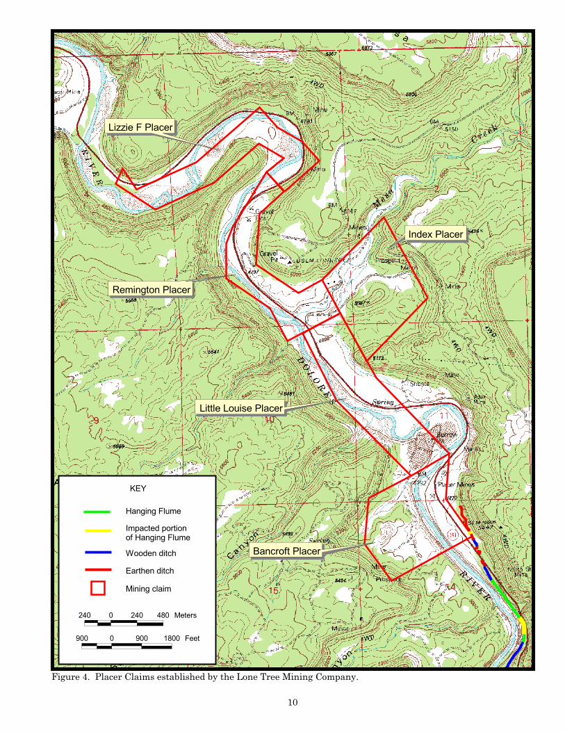
The Hanging Flume (5MN1840) was a high-capital venture. Location Certificates were filed
on five placer claims by the Lone Tree Mining Company between 1883 and 1885 (Montrose County
Recorders Office, Book 13, Pages 38, 87-89, 93, and 94). The claims were along the gravel beds of the
Dolores River approximately 4 miles north of the confluence of the Dolores and San Miguel rivers.
From south to north, these were the Bancroft Placer (Mineral Survey No. 2243), the Little Louise
Placer (Mineral Survey No. 2247), the Index Placer (Mineral Survey No. 2246), the Remington Placer
(Mineral Survey No. 2244), and the Lizzie F. Placer (Mineral Survey No. 2245) (Figure 1). All but
the Remington Placer were patented in May 1885. The Lone Tree Mining Company was composed of
investors from Salt Lake County, Utah, with the Articles of Incorporation filed in Salt Lake City in
May 1885. The corporation was made up of six investors with $1 million (10,000 shares at $100
each) in capital stock (Lone Tree Mining Company 1885).
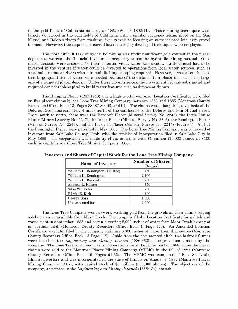
Investors and Shares of Capital Stock for the Lone Tree Mining Company.
Name of Investor Number of Shares
Owned
William H. Remington (Trustee) 750
William H. Remington 2,200
William H. Bancroft 750
Andrew L. Horner 750
Silas W. Eccles 750
Edwin E. Rich 750
George Goss 1,500
Unaccounted for 2,550
The Lone Tree Company went to work washing gold from the gravels on their claims relying
solely on water available from Mesa Creek. The company filed a Location Certificate for a ditch and
water right in September 1885 and began diverting 2,000 inches of water from Mesa Creek by way of
an earthen ditch (Montrose County Recorders Office, Book 1, Page 570). An Amended Location
Certificate was later filed by the company claiming 5,000 inches of water from that source (Montrose
County Recorders Office, Book 13 Page 119). Aside from the documented ditch, two bedrock flumes
were listed in the Engineering and Mining Journal (1886:360) as improvements made by the
company. The Lone Tree continued washing operations until the latter part of 1888, when the placer
claims were sold to the Montrose Placer Mining Company (MPMC) in the fall of 1887 (Montrose
County Recorders Office, Book 19, Pages 61-65). The MPMC was composed of East St. Louis,
Illinois, investors and was incorporated in the state of Illinois on August 8, 1887 (Montrose Placer
Mining Company 1887), with capital stock of $5 million (500,000 shares). The objectives of the
company, as printed in the Engineering and Mining Journal (1888:134), stated:
�������������
���������
����������������
���� �������
������������
�����������
�� ����������
������������
����������� �������������������
���
!" " !" !#" ���� �
$"" " $"" %#"" ����
������������
���������������� ���������������������������������������� �������
��

“The object is to acquire by location, purchase, or lease mining claims, mill-sites, and
water rights and to engage in the business of mining and sluicing, the reduction of
ores, and the purchase or sale of the products of mines and mills in any portion of
Colorado.”
Montrose Placer Mining Company Investors.
Name of Investor Number of
Shares Value of Shares
Nathaniel P. Turner 5 $50
Louis Phillippi 5 $50
J. O. Ackerson 5 $50
Matthew P. Elliott 5 $50
Gaston Meslier 5 $50
W. J. Nichols 5 $50
T. D. Gildersleve 5 $50
George F. Neale 5 $50
W. H. Hallett 5 $50
J. Herrin 5 $50
B. Allison 5 $50
A. L. Horner 499,925 $4,999,250
William Flonelly 5 $50
Oscar G. Murray 5 $50
J. E. Blythe 5 $50
T. B. Taylor 5 $50
The company was managed by Nathaniel P. Turner, rumored to have been an experienced
miner from California (Hall 1895:235). It is not certain where Turner was actually from because he
was listed in three different court documents as being from Denver, Colorado; Sumner County,
Tennessee; and St. Louis, Missouri.
It was not long before the MPMC was aware that substantial washing operations would be
necessary if the placer mining venture along the Dolores River was to become profitable. In turn,
this also meant that the seasonal water source provided by Mesa Creek would no longer be adequate
for the increased scale of the operation. In response to this limitation, the Montrose Placer Mining
Company began the construction of a flume that would transport a steady supply of water from the
San Miguel River to the patented claims. The company appears to have begun the construction of
the flume shortly after acquiring the placer claims from the Lone Tree Mining Company in the
spring of 1889 (Rockwell 1999; Silver 2003). The beginning construction date can be substantiated
by an article that appeared in the Grand Junction News on April 6, 1889, that stated that “the
Montrose Placer Company, operating on Mesa Creek and the Dolores, expect to have their big canal
finished this summer.” Still further confirmation of the date is provided by a lien filed by Buddecke
and Diehl against the MPMC on July 15, 1889 (Montrose County Recorders Office, Book 7, Page
144). The wording of the lien makes direct reference to the flume, which indicates that the flume
was still under construction at the time the lien was filed. It is clear by the lien that the MPMC was
having some difficulty meeting the financial obligations necessary to build a large waterworks like
the flume. Regardless of the financial setbacks, the flume construction continued until May 1891
when it was completed to the Bancroft Claim, the southernmost of the claims held by the company.
The completed flume was 10 miles long, though it was originally planned to be 13½ miles long.
Evidently the company was financially unable to construct the final 3½ miles, which would have
provided water to all of their claims, and planned to construct the remainder after they had profited
from mining on the Bancroft. The completion of the flume was chronicled in two different articles

printed in the Grand Junction newspaper. The first article was printed on May 16, 1891 and stated
that
“Capt. N. P. Turner, general manager of the Montrose Mining Co., the placers on the Dolores
River, in the vicinity of Mesa creek, arrived here from St. Louis Thursday night, en route for the
mines. He reports that washing has been in progress for the past ten days and everything looks
promising for a speedy and profitable return to the company which has expended so much money in
the development of these placers during the last three years (Grand Junction News May 16, 1891:8).”
The second article, a statement by a Mr. W. P. Ela, gave a first-hand account of the hydraulic mining
operations taking place on MPMC placer claims.
“I was very surprised and agreeably so with what I saw there. I had always looked
upon those placers as poor property and upon the company with a good deal of
distrust. But I am ready to acknowledge that I was wrong. The flume which
supplies the water for washing out the gold is a most wonderful affair, for almost 7
miles this flume was built right along on the sides of a perpendicular wall of stone, in
some places ninety feet above the river bed. It was two years or more in course of
construction and is a magnificent piece of work (Grand Junction News July 4,
1891:3).
In 1892, a year after the MPMC completed construction of the Hanging Flume, the General
Land Office (GLO) contacted the company to inform them that payment for the Remington Placer
Claim had not been made to the office. Unbeknownst to the MPMC, the oversight was made by the
previous owners (Lone Tree Mining Company) and stemmed from a misappropriation of funds by the
receiver of the GLO. The request for payment came at a time when the flume construction had
financially drained the company and any additional expenditure was impossible. As a result, the
MPMC lost their holdings and Nathaniel Turner was financially embarrassed, resigned from the
company, and left Colorado (Turner 1899). Turner returned to Colorado and purchased the company
holdings from a sheriff’s sale in September 1893 (Montrose County Recorders Office, Book 26, Page
335). In an effort to protect the investors of the MPMC, Turner established the Vixen Alluvial Gold
Mining Company (Vixen). He conveyed ownership of the property to the Vixen in 1897 and served as
its general manager (Turner 1899). In 1897, the Vixen prepared to construct the remaining 3½
miles of the flume. To capitalize the project, they took out a $21,000 loan from Frank D. Catlin, who
was issued a Deed of Trust for the flume and mining property as collateral (Montrose County
Recorders Office, Book 60, Page 541). Financial difficulties plagued the Vixen, and it became
painfully obvious that the gold washed from the gravels was too fine to be collected efficiently in the
sluice boxes and construction of the remaining 3½ miles of the flume was evidently never started.
On April 5, 1899, J. S. Hart was given a court judgment against the Vixen for money owed him for
performing improvements on the Vixen placer claims (Montrose County Recorders Office, Book 26,
Page 335). As a result, the Vixen property was sold by the County Sheriff to Hart, with the deed
available to him on February 17, 1900 (Montrose County Recorders Office, Book 60, Page 541). Hart
assigned the right to the deed to W. E. Bridgman, who received the deed on February 19, 1900
(Montrose County Recorders Office, Book 75, Page 178). Bridgman is assumed to be associated with
the Montrose Mining Company because the next day, on February 20, 1900, he passed the property
to the Montrose Mining Company by Quit Claim Deed (Montrose County Recorders Office, Book 72,
Page 203).
The Montrose Mining Company was incorporated in Arapahoe County, Colorado, on January
25, 1900. The corporation was composed of three individuals, R. S. Morrison, E. D. DeSoto, and N. L.
Burton, with capital stock of $100,000 (Montrose Mining Company 1900). Beginning in 1902, the
company filed annual reports and, according to the reports, the mining company was still subject to
the $21,000 loan from Frank Catlin, which was to be paid in full on July 1, 1907 (Montrose Mining
Company 1902-1904). For the years 1902 and 1903 the company failed to list any improvements to

the property. However, in the 1903 Annual Report filed on January 19, 1904, the company claimed
they had “washed for about four weeks, when the water gave out” (Montrose Mining Company
1904:2). Evidently, the flume must have suffered some catastrophic failure that the company was
unable or unwilling to repair. After 1904, the Montrose Mining Company stopped filing Annual
Reports and the company sold their placer holdings to Guy V. Sternberg on January 13, 1909
(Montrose County Recorders Office, Book 110, Page 101); it is not clear if the debt to Catlin was ever
repaid. No further evidence exists of the flume being used for mining purposes.
Construction History
The Hanging Flume would have been a major engineering and financial undertaking even by
today’s standards. Frank Hall (Hall 1895) interviewed Nathaniel Turner in Ouray, Colorado, and,
later, in Montrose, Colorado, about the particulars of the Hanging Flume construction. Turner
stated that the flume required 1,800,000 feet of lumber in its two-year construction, it carried 80
million gallons of water in 24 hours, and cost over $100,000. The exact cost of the flume construction
has been a subject of local legend speculated to have been as high as $1 million (Rockwell 1999:163).
In a statement given to the General Land Office, Turner stated that between 1888 and 1892 the
company made improvements to their property in the amount of $175,000. However, the amount
spent on the flume would have been around $165,000, because the total also included $10,000 spent
on pipe, piping, and five buildings constructed on one of the placer claims. Another cost estimate of
$173,000 appeared in the Engineering and Mining Journal (September, 18, 1897:345), suggesting
that the actual cost was between $165,000 and $173,000.
Interestingly, in at least two court documents dealing with transactions of the MPMC, the
flume is recorded as 13½ miles long (Montrose County Recorders Office, Book 71, Page 319; Book 26,
Page 323). However, the archaeological recording of the Hanging Flume indicates that the total
length of the flume is about 9.78 miles long and could not have exceeded 10 miles. As it was built,
the flume carried water to the boundary of the southernmost placer claim (Bancroft Placer), but it
appears that the original plan was to extend the flume an additional 3½ miles farther northwest to
supply water to the remaining four placer claims. This scenario is echoed in an 1897 article that
appeared in the Engineering and Mining Journal (1897:345). The article stated that MPMC had
constructed 10 miles of the flume before the project was suspended in 1893. Although the article
refers to the company as the MPMC, the company had already been reorganized as the Vixen
Alluvial Gold Mining Company (Vixen) by 1897. Construction to complete the last 3 or so miles of
the flume was planned by the company at an estimated cost of $30,000. It appears that the flume
may have been engineered and designed to be 13½ miles long and serve all five of the company’s
placer claims. However, financial difficulties may have limited construction to only the first 10
miles. This would have enabled the company to initiate hydraulic mining on the Bancroft Claim,
with the plan that profits from the mining would enable the completion of the project.
According to different sources, the flume construction began at the northern end where most
of the hanging segments of the flume were located. It is believed that this allowed for the most
difficult and labor intensive segments of the flume to be constructed first. It was also the point
closest to the lumber source being supplied to the construction (Peterson 1963; Engineering and
Mining Journal May 17, 1890). The lumber used in the construction of the flume was supplied to the
MPMC by Buddecke and Diehl, a mercantile and freighting company owned by A.E. Buddecke and
Charles Diehl and based in Montrose. This is substantiated in the lien filed by Buddecke and Diehl
against the MPMC mentioned above. In the lien filed at the Montrose County Courthouse on July
15, 1889, Buddecke and Diehl presented an itemized list outlining the work completed by them for
the flume.

Itemized List of Work Performed by Buddecke and Diehl.
Sawmill, boiler, engine and necessary buildings $6,500
Building roads $3,500
Cutting 140,000 feet of logs $1,750
Sawing 1 million feet of lumber $12,240
Delivering 280 thousand feet of lumber $3,024
Total Due $27,014
Credit by cash $3,800
Balance Due $23,214
An interview conducted with Mrs. Charles Diehl in 1936 (Peterson 1963:131) revealed that
the timber used on the flume was initially cut at a sawmill on Pine Flats, west of Buckeye Reservoir
in Utah. This information was confirmed in an interview by Marie Templeton with James Patterson
(Templeton 2002:123). Pine Flats was just over the Colorado state line about 9 miles northwest of
Paradox, Colorado, and approximately 18 miles west of the Hanging Flume. The timber in that area
was preferred because trees were of immense size and produced virtually knot-free lumber (Peterson
1963:131). Setting up the sawmill on Pine Flats appears to have been a substantial undertaking,
requiring “ten yoke of oxen to pull the boiler alone up the mountain” (The Altrurian September,
1895:2-3). However, because the cutting was unlawfully done on Utah State lands, the operations
had to be moved across the state line into Colorado after one cutting season. The sawmill was moved
1.5 miles east to Carpenter Ridge. After construction of the flume, the sawmill was sold to the
Colorado Co-operative Company of Nucla, Colorado, and used to mill lumber for an irrigation flume
(The Altrurian September, 1895:2-3).
The road constructed from the sawmill on Carpenter Ridge to the flume was built down Red
Canyon and crossed the Dolores River at a natural ford near the northern end of the Hanging Flume
(Peterson 1963:131). The road is still evident in Red Canyon and was identified during a
reconnaissance survey by Alpine in October 2004. The area was visited with local historian Marie
Templeton. The road is of narrow, cut-and-fill construction of some antiquity and has fragmented
iron wagon parts, pieces of large chain links, and lumber with cut nails lying within its confines. It
also appears that additional lumber may have been supplied to the flume by a second mill. The
second sawmill was believed to have been operated by Elisha Darling (Peterson 1963), who owned
and operated a number of sawmills in the Montrose area and was known to have supplied lumber to
Buddecke and Diehl for resale (Montrose County Recorders Office, Book 29, Page 3). It is speculated
that the lumber supplied by Darling may have been freighted to the flume from one of his sawmills
on the Uncompahgre Plateau southwest of Montrose. Darling’s sawmill was close to a freighting
road built by Buddecke and Diehl to supply the MPMC during the construction of the flume. The
road is described as crossing “the Uncompahgre Divide at Cold Springs north of what is now
Columbine Pass, wound through the pine timber, crossed Spadlin and Tabaguache Parks, then
dropped down the Dolores River” (Peterson 1963:128). The construction of the freighting road was
funded by private business and Montrose County and was expected to bring placer mining and
livestock business to Montrose, amounting to $100,000 from the gold placers alone (Grand Junction
News February 16, 1889:2). Originally, Buddecke and Diehl freighted supplies from Whitewater,
near Grand Junction, Colorado. The supply shift was viewed as a point of contention between
Montrose and Grand Junction, with the Grand Junction News (February 16, 1889:2) pointing out the
eminent loss of business to the town and faulted the Mesa County commissioner for not fully
considering building a supply route to the Hanging Flume. According to the Grand Junction News
(March 16, 1889:3) Montrose County Commissioner W. A. Thomas was quoted as saying “the county
board of Montrose County have laid out a road to the placer mines on Mesa creek and that it will be
built at once.”

John Christian
John Christian is rumored to have come to the Dolores and San Miguel canyons area after
many of the silver mines in the San Juan Mountains began to close (Rimrocker 2004), probably a
result of the Panic of 1893. It is not certain exactly what year Christian came to the area or if he
was ever associated with the construction of the flume. However, according to an affidavit
pertaining to the Index Placer Claim, Christian is documented to have been in the area as early as
1899, eight years after the completion of the flume (National Archives Affidavit Mineral Entry No.
28). The 1899 date of arrival for Christian is further substantiated by a Location Certificate he filed
in 1901 for the Gladyse Placer along the Dolores River (Montrose County Recorders Office, Book 76
Page 408). It has been suggested by local histories that Christian built his cabin on the site after he
became too old to work, sometime around 1906 (Silver 2003:8). John Christian never formally
acquired his homesite from the public domain. It is not certain whether Christian continued to mine
the area after moving to the homesite in 1906, but what is certain is that he used the site as a base
for dismantling the flume and salvaging its lumber.
Photograph of John Christian sitting on the steps of his cabin. Photograph
taken between 1906 and 1915.
It is believed that the activity of John Christian at the site masks an earlier construction
camp component that was contemporaneous with the construction of the Hanging Flume. The
evidence for this is in the presence of the forge and the location of the site at the center of a trail
system that emanates from the site to various points along the flume. The forge is similar in its
construction to other forges found associated with the construction of the flume. The site and the
canyon are accessed from the east-northeast by a substantial trail that would have been wide enough
(8 feet) to accommodate freight wagons. Five trails extend to the north, west, and east from the site
area providing accesses to a large portion of the flume on the canyon and to the Dolores River. The
complexity of the trail system indicates that the site served as an important strategic point for
movement of both materials and labor.

The Hanging Flume Description
According to court documents, the Hanging Flume was originally slated to be 13½ miles long
with the head of the ditch taking water from the San Miguel River at a point east of the abandoned
uranium mining settlement of Uravan, Colorado (Montrose County Recorders Office, Book 71 Page
319). However, the archaeological recording of the Hanging Flume indicates that the total length of
the flume is about 9.78 miles long and could not have exceeded 10 miles. The Hanging Flume, as it
is known, was originally named the Dolores and San Miguel Ditch and was constructed along the
north side of the San Miguel to its junction with the Dolores River and then followed along the
canyon of the Dolores as the river turns and continues north. The flume is on lands administered by
the Bureau of Land Management, Montrose Field Office, and on private land, meandering along the
path of the river and traversing the canyon landscape. The canyon environment is characterized by
steep vertical sandstone walls with steep slopes at their base composed of colluvium and covered
with talus. The flume begins at an elevation of 4,980 feet on its eastern end and terminates at an
elevation of 4,890 feet on the north creating a drop of 90 feet from end to end. The flume passes
through two environmental zones, divided east and west. The eastern zone is composed of riparian
plants such as cottonwood, tamarisk, willow, and cattail along the river giving way to prickly pear
cactus, sparse juniper, and a variety of grasses as the flume passes along the northern edge of the
floodplain of the San Miguel River. As the flume reaches the mouth of the San Miguel River canyon
at its junction with the Dolores River, the western vegetation zone begins and continues to the
flume’s northern terminus. Vegetation is characterized by dense stands of pinyon and juniper
growing along the upper rim of the Dolores River canyon and its lower benches. The understory of
the woodland is made up of a variety of plants including mountain mahogany, Mormon tea, prickly
pear cactus, yucca, barrel cactus, and cheatgrass.
The Hanging Flume was originally recorded by the Montrose District Office of the Bureau of
Land Management in July 1970, but does not appear to have been part of any particular cultural
resource inventory, and its recording was never incorporated into a report. The recording was
limited to a general description of the site with no condition assessment done at the time. The site
was rerecorded in 1974 with a National Register of Historic Places nomination prepared for the site
in September 1977. The flume was officially determined eligible and subsequently listed on the
National Register in July 1980.
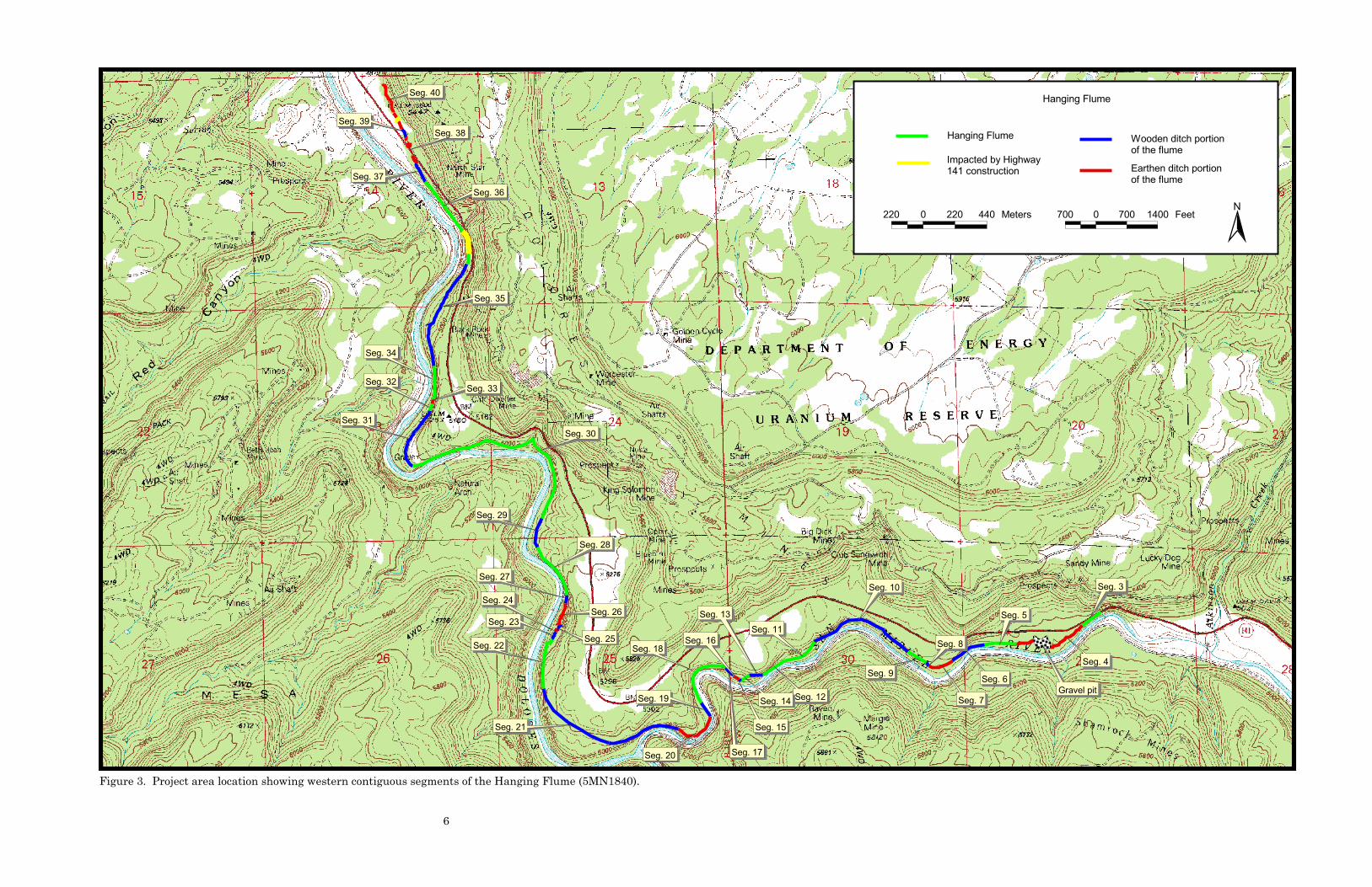
Alpine revisited the site for the 2004 Hanging Flume Project and recorded 7.15 miles of the
visible linear footprint and its associated construction features. The 7.15 miles of the flume included
the entire western half of the flume made up of contiguous segments (Segments 3-40 and two
segments (Segments 1 and 2) at the far eastern end of the flume near the abandoned uranium
mining settlement of Uravan, Colorado. These two segments are recognized as being the beginning
of the flume at the point where water was diverted from the San Miguel River. Because of the
nature of the canyon environment, some segments of the flume could not be directly accessed.
Therefore, observations about structural characteristics were gathered with the aid of binoculars
either from the level of the river below the flume or from above, on the rim of the canyon.
The remaining 2.63 miles of the flume unaccounted for during the recordation are believed to
have been earthen ditch segments. They were removed by the construction of Highway 141 and
settlement ponds and other workings associated with the uranium mill at Uravan, Colorado. The
flume was recorded with the aid of a GPS, not only to record the entirety of the linear but to
document the various structural conditions of the site as well. Structural distinctions along the
length of the flume were separated into three different construction categories and included earthen
ditch, wooden flume on trestle supports, and hanging flume.

Segments of Flume Conditions Documented During the Hanging Flume
Project.
Segment
No. Segment Type† Length in Feet
Beginning and
Ending Foot Mark
1 Earthen Ditch 502 N/A
2 Earthen Ditch 1,717 N/A
3 Hanging Flume 521 0-521
4 Earthen Ditch 1,745 521-2,266
5 Hanging Flume 742 2,266-3,008
6 Wooden Flume 832 3,008-3,840
7 Earthen Ditch 587 3,840-4,427
8 Wooden Flume 85 4,427-4,512
9 Hanging Flume 485 4,512-4,997
10 Wooden Flume 2,537 4,997-7,534
11 Hanging Flume 861 7,534-8,395
12 Hanging Flume 597 8,395-8,993
13 Wooden Flume 296 8,993-9,288
14 Hanging Flume 236 9,288-9,524
15 Wooden Flume 43 9,524-9,567
16 Earthen Ditch 62 9,567-9,629
17 Wooden Flume 252 9,629-9,881
18 Hanging Flume 1,492 9,881-11,373
19 Wooden Flume 368 11,373-11,741
20 Earthen Ditch 1,025 11,741-12,767
21 Wooden Flume 3,698 12,767-16,464
22 Hanging Flume 1,222 16,464-17,686
23 Wooden Flume 176 17,686-17,862
24 Earthen Ditch 88 17,862-17,950
25 Wooden Flume 71 17,950-18,021
26 Earthen Ditch 553 18,021-18,574
27 Wooden Flume 192 18,574-18,766
28 Hanging Flume 1,315 18,766-20,081
29 Wooden Flume 701 20,081-20,782
30 Hanging Flume 4,912 20,782-25,694
31 Wooden Flume 1,491 25,694-27,185
32 Hanging Flume 160 27,185-27,345
33 Earthen Ditch 115 27,345-27,460
34 Hanging Flume 763 27,460-28,222
35 Wooden Flume 2,623 28,222-30,845
36 Hanging Flume 2,195 30,845-33,040
37 Wooden Ditch 459 33,040-33,500
38 Earthen Ditch 677 33,500-34,177
39 Wooden Flume 213 34,178-34,390
40 Earthen Ditch 1,159 34,390-35,549
†The term Wooden Flume refers to wooden flume on trestle supports

Seg. 1Seg. 2
Seg. 3
Seg. 4
Seg. 1Seg. 2
Seg. 3
Seg. 4
Project area location showing eastern segments of the Hanging Flume (5MN1840).
5MN1840
Meters220 0 220
Feet700 0 700
Earthen ditch portionof the flume
Hanging Flume
������
������
������ �
������
������
������
������
������
�������
�������
�������
�������
�������
�������
�������
�������
�������
�������
�������
�������
�������
�������
�������
�������
�������
�������
�������
�������
��������������
������� �������
�������
�������
��������������
��������������
�������
������������ ��������� !"��#�� ! $����!�� ����� �� !
%�����%�#��
& ��!�� ����� �� ! %�����%�#��
�!� !��'�#��
��� � ��� ��� (����" ��� � ��� ���� '��� )
�!� !��'�#��
�
�������������� ��������� ���������������������� ������������������������������������������������

Eleven segments of earthen ditch totaling 8,230 feet (1.6 miles) were identified during the
recordation. The earthen ditch method was employed predominantly near the origin of the flume
where the linear crosses a fairly level, broad alluvial bench on the north side of the San Miguel
River. Unquestionably, the first portion of the route beginning at the headgate would have been the
longest segment of earthen ditch with an approximate length of nearly 3 miles. Unfortunately, only
2,219 feet (0.4 miles) of this segment of earthen ditch appears to have survived the impacts incurred
as a result of Highway 141 construction and the mining activity at Uravan. An earthen ditch was
also employed when alluvial-covered benches or colluvial slopes within the canyon were encountered.
The identified earthen ditch segments vary both in their width and depth owing principally to silting
during the use of the ditch and post-abandonment soil accumulation. In their current condition, the
earthen ditch segments average between 12 and 15 feet wide, with a depth ranging between 2 and 4
feet. For the segments of the ditch that traverse the benches, the construction method is relatively
standard: a cut-and-fill method with the profile of the ditch being U-shaped with sloping sides. The
spoil from the ditch excavations was placed along the downslope edge of the ditch and further served
to fortify the downhill side of the ditch. In areas where earthen ditches were used to transport water
across colluvial slopes, the path of the ditch was excavated into the slope with the resulting soil
being placed along the downslope edge of the ditch and used as fill to create the bed of the ditch. To
avoid slope erosion, the grade of the ditch’s uphill bank was sloped. In addition to the excavated
segments of the ditch, at least three areas were recorded that utilized masonry features (Features 2,
5, and 13) to strengthen the banked segments of ditch. In two of these instances (Features 2 and 5),
masonry walls were built to retain soil in low-lying areas, creating a grade for the ditch. In the final
instance (Feature 13), a masonry retaining wall was constructed along 20 feet of the downslope edge
of the ditch to retain soil and create a path for the ditch across a rocky section near the northern
terminus of the slope.
Sixteen segments totaling 14,037 feet (2.6 miles) of wooden flume on trestle supports were
recorded, making up a substantial portion of the 7.15 miles of the recorded flume. Unlike the
earthen ditch and hanging segments, the wooden flume segments are not readily visible owing to
post-abandonment lumber salvaging. However, construction elements indicative of the wooden
flume segments are still discernible on the landscape and include chiseled notches in the rock,
lumber and nail scatters, and an occasional horizontal beam and diagonal still attached to sandstone
outcrops or the surface of boulders. The canyon environment necessitated the construction of the
wooden flume as it functioned to transport water over uneven areas of the terrain primarily along
narrow, talus benches where it was not conceivable to excavate a ditch or attach a flume box to the
rock surface of the canyon. Although only a minimal amount of wooden flume has survived, other
flumes constructed for hydraulic mining indicate that the flume boxes were constructed in the same
manner as the hanging flume portions but were elevated above the ground on wooden trestle
supports with varied trestle leg heights to negotiate the topography (Bowie 1885:143; Willson
1898:46). Based on these historic examples, the trestles were built using two vertical post legs,
probably 8 by 8-inch or 8 by 10-inch, and capped with an additional beam of like dimensions. Two
pieces of lumber were attached diagonally between the post legs as bracing to deter lateral
movement occurring under the weight of the flowing water or windy conditions. As witnessed by the
remains in four different segments (Segments 21, 25, 29, and 35), wooden flume segments were on
horizontal beams anchored to either boulders or rock outcrops. These examples show that horizontal
beams were used mainly in areas that were transitioning from hanging portions to earthen ditches
and were supported by vertical timbers.
The term “horizontal beam” is used herein to mean the 8 by 8-inch horizontal timber support
anchored to the wall of the canyon on which the flume box was set. Beams were spaced at 4-foot
intervals and were used on wooden flume sections and hanging sections. In the case of the Hanging
Flume, two types of horizontal beams were recorded along its length. Hanging beams were anchored
to the canyon walls, and beams on trestle supports or anchored to boulders were used on wooden
flume segments of the flume. In the majority of the hanging segments, horizontal beams were

supported from below by 8 by 8-inch diagonals attached to the outboard ends of the horizontal beams
with mortise and tenon joints fastened together with either wooden pegs or threaded bolts. In some
cases, the joint was secured further with a vertical bolt through the diagonal and the horizontal
beam just a few inches inward from the mortise and tenon joint. In still other instances, the joint
was supported by a board gusset nailed across the side of the joint. It was also found that further
support for the horizontal beam and diagonal was sometimes provided by 4 by 4-inch vertical post
braces recessed into the horizontal beam and nailed between the beam and the diagonal on their
inboard ends. The bases of the diagonals were often miter cut and anchored to the face of the cliff
using one of three techniques. The most common method involved the use of a wooden shear block
placed at the base of the diagonal at the cliff face with the diagonal toe-nailed to the block. The
blocks were usually 4 inches wide and 10 inches long and attached to the rock surface using two
parallel 1¼-inch-diameter iron pins.
A second method of anchoring the diagonals also involved the use of shear blocks as
described above with the diagonal set in shallow notches chiseled into the surface of the rock with
additional support provided by a shear block below.
The final method of anchoring the diagonal dispensed completely with the shear block and
relied on a deeper chiseled notch. In these instances, the base of a diagonal was miter cut, creating a
horizontal surface, and placed on the ledge created by the notch. Once in place, the diagonal was
secured by a single 1¼-inch-diameter iron stop rod placed in a hole drilled at an angle into the cliff
face.
The flume box constructed to carry the water has largely been removed from the site, leaving
only minimal traces of its construction. Remains of the flume box exist in only the most inaccessible
locations and consist of stringers, sills, and portions of the floor boards (Segments 12, 25, 28-30, and
34). Although much of the flume box has been salvaged, an article in the Engineering and Mining
Journal (1890:563) shows an illustration of the flume detailing its construction. The illustration,
coupled with information gathered through the documentation of the flume, has aided in
understanding how the flume box was built The horizontal beams and diagonals supported two 16-
foot-long, 4 by 8-inch, generally parallel, longitudinal stringers on the inboard and outboard ends of
the horizontal beams. The ends of the stringers were overlapped and toe-nailed across the horizontal
beams. The stringers supported 4 by 6-inch sills that were toe-nailed perpendicular to the stringers
at 4-foot intervals. The sills served as the base of the box and had four 1 by 16-inch longitudinal
planks nailed to them, creating the floor of the box. The sides of the box were also made of 1 by 16-
inch planks nailed to vertical side posts set into notches in the sills. The height of the sides of the
flume box is not certain but the journal article indicates that the sides were probably at least three
boards high, equal to 4 feet. The journal illustration also suggests that horizontal tie board were
nailed to the tops of the opposite vertical side posts to keep the walls of the box from spreading; this
was typical for flume box construction.
In addition to the earthen and wooden ditches, 13 segments, making up 15,501 feet (2.9
miles) of hanging flume, were documented during the course of the project. The hanging portions of
the flume consisted of horizontal beams and diagonals found anchored to the wall of the canyon
through the use of various bracket types. The bracket types were documented and defined during
the rappelling drops by Vertical Access and personnel from Robert Silman Associates (2004). Based
on the rappelling documentation and archaeological recordings of the various segments, bracket
types fall into four distinct categories (Types A-D) with variances noted within the Type A (A1 and
A2) and Type B (B1-B3) bracket categories. All brackets were made from 1¼-inch-diameter iron
rods. The Type A1 brackets support the flume box in three or more places, including anchoring the
horizontal beam to the canyon wall with the addition of a rod placed through the inboard end of the
beam and held by a washer and square nut. The rod on the horizontal beam had either an eye or a
hooked end that was attached to a supplemental rod anchored to the cliff face. A variation of the

Type A1, referred to as the Type A2, was used in areas with a slight overhang above the horizontal
beam and diagonal and included the addition of a cripple post at the inboard end of the horizontal
beam. The cripple was placed between the overhang and the beam.
The Type B2 bracket was U-shaped and anchored to the cliff face immediately above the
horizontal beam. In these cases, one side of the “U” was butted against the inboard end of the
horizontal beam with the other side of the “U” extending upward through the beam. An interesting
addition to the B2 bracket was the use of a metal strap with a hole on each end. One end of the
strap was slid onto the rod spanning the opening of the U-shaped bracket and fastened on the short
end of the bracket on the outboard end with a 2½-inch-square nut. The strap appears to have
functioned to keep the bracket from spreading. Two grooves were cut into the inboard end of the
horizontal beam: a vertical groove for the vertical leg of the bracket and a horizontal groove on the
underside of the beam to hold the underslung portion of the bracket. The Type B2 brackets are
considered to be unusual in flume construction and were recorded only in Segment 5, on the
upstream portion of the flume.
The remaining Type B bracket is the Type B3 variant and was limited to the western end of
Segment 5. The Type B3 bracket is a vertical rod hooked into a downward drill hole on the cliff face
and placed vertically through a hole in the horizontal beam. The rod was secured to the beam with a
round washer and a square nut (see Robert Silman Associates, P.C. 2004:3-5). It appears that the
Type B3 bracket was used on an area of the cliff face where the sandstone near the horizontal beam
was not structurally sound enough to hold a typical B1 or B2 type bracket.
The Type C bracket is similar to the Type A bracket in that a diagonal rod was anchored to
the cliff face above the flume box. The difference between the Type C and Type A brackets is that
the rod is not attached to the horizontal beam as it is in the Type A bracket, but instead passes
through an angled hole in the horizontal beam and is connected to the diagonal (see Robert Silman
Associates, P.C. 2004:6-7). The rod is secured to the diagonal with a washer and a square nut.
The final bracket is the Type D bracket, which was used on Segment 30 of the flume where
the face of the cliff overhangs and required specialized anchoring methods. In the instance of
Segment 30, the Type D bracket enabled the flume to be suspended without the support of diagonals.
The Type D bracket consisted of a vertical rod bolted to the outside of the horizontal beam, ascending
above the height of the flume box and joined with interconnected hooks to a second rod angling
upward and inward to the face of the cliff. To prevent the vertical rod crushing the top of the flume
box, a 4 by 4-inch post was added between the outer side board of the flume box and the upright rod,
with the rod secured to the post by a wire staple (for detailed description of Type D bracket, see
Robert Silman Associates, P.C. 2004:7-8).
In addition to the recordation of the Hanging Flume, 22 features were also documented along
its length. The majority of the construction features documented were characterized as masonry
abutments built primarily as supports at key transition points between earthen segments and
wooden trestles. The transitions were necessary in order to transport water over drainages and
rocky talus areas of the canyon where it was not feasible to attach a flume to the canyon wall or to
extend the earthen ditch. Other features included anchor points along the rim of the canyon above
the flume that may have been used during the construction of the hanging segments of the flume; an
overflow ditch (Feature 21); and two pressure box locations (Features 20 and 22). All features were
assigned sequential numbers (1-22) beginning at the eastern end of the flume.

8x8”
TOP VIEW
4x4” vertical bracebolt
bolt
mortise and tenon joint
Horizontal beam and diagonal construction: a) horizontal and diagonal with bolt , b) mortise and tenon, c) gusset, d) top view of horizontal beam and diagonal.
gusset instead of bolt
0 1 2
Feettenon
mortise joint
boltbolt
4x4” recessed into arm and brace 1/2 its thickness and nailed
mortise and tenon joint
b.
c.
a.
d.
20
Horizontal Beam
Diagonal

1 1/4’’ diameter iron stop rod (single)
Toe Nail
1 1/4’’ diameter iron rod pins (2)
Stop Nail
Block mitered to conform to cliff face in some instances
SIDE VIEW
1 1/4’’ diameter iron rod pins
Toe Nail
END VIEW
Stop Nail
Stop Nail
Block mitered to conform to cliff face in some instances
Toe Nail
1 1/4’’ diameter iron rod pins (2)
Diagonal anchoring methods: a) shear block, b) shear block and notch, c) notch and stop pin.
a.
b.
c. ..

0 1 2
Feet
0 1 2
Feet
0 1 2
Feet
Type A bracket with variations of anchoring method.
23

0 1 2
Feet
4x8’’ stringers
6x6’’ sill
1x16’’ side and floor boards
4x4’
’ flu
me
post
4x4’
’ flu
me
post
2x4” top flume bent brace
tenon
mortise joint
Construction of flume box on Hanging Flume (5MN1840).
REFERENCE CITED
The Altrurian
September 1895
Bowie, Aug. J. Jr.
1885 A Practical Treatise on Hydraulic Mining in California. D. Van Nostrand, Publisher,
New York.
Engineering and Mining Journal
1886 May 15, 1886 41 (20)
1888 August 8, 1888 46 (7)
1897 September 18, 1897 64 (20)
1890 May 17, 1890 49 (12)
Grand Junction News
1889 February 16 and March 16
1890 May 16
1891 July 4
Hall, Frank
1895 History of Colorado. Vol. 4. The Blakely Printing Company, Chicago.
Hagwood, Joseph J. Jr.
1981 A History of the Hydraulic Mining Industry in the Western Sierra Nevada of
California, and of the Government Agency Charged with its Regulation. The
California Debris Commission, Sacramento.
Lone Tree Mining Company
1885 Articles of Incorporation, May 11, 1885. On file at Utah State Archives, Salt Lake
City.
Montrose County Courthouse, County Recorders Office
Book 1, Page 570
Book 7, Page 144
Book 13, Pages 38, 87-89, 94, and 119
Book 19, Pages 61-65
Book 26, Pages 323 and 335
Book 29, Page 3
Book 60, Page 541
Book 71, Page 319
Book 72, Page 203
Book 75, Page 178
Book 76, Page 408
Montrose Mining Company
1903 Annual Report of Mining Corporation, 1902, January 6, 1902. On file at the Colorado
State Archives, Denver.
1904 Annual Report of Mining Corporation, 1903, January 10, 1903 On file at the
Colorado State Archives, Denver, Colorado.
1905 Annual Report of Mining Corporation, 1904, January 19, 1904. On file at the
Colorado State Archives, Denver.
Montrose Placer Mining Company
1900 Articles of Incorporation, February 21, 1900. On file at State Archives, Denver.
Montrose Placer Mining Company
1887 Articles of Incorporation, August 8, 1885. On file at Illinois State Archives, Chicago.
Parker, Ben H. Jr.
1974 Gold Placers of Colorado. Quarterly of the Colorado School of Mines, 69 (4) 172-184.
Peterson, Ellen Z.
1963 The Hanging Flume of Dolores Canyon. Colorado Magazine 40 (2):128-131.
Robert Silman Associates, P.C.
2004 Existing Condition Assessment of Montrose Placer Mining Company Hanging Flume
Uravan, Colorado. Robert Silman Associates, New York. Submitted to the Western
Colorado Interpretive Association Delta, Colorado.
Rimrocker
2004 Club Ranch. http://rimrocker.org/club%20ranch%202.htm, accessed August 31, 2004.
Rockwell, Wilson
1999 Uncompahgre County. Western Reflections, Inc., Ouray, Colorado.
Silver, Estalee
2003 The Magnificent Hanging Flume, 1889-1891. Estalee Silver Collection, Grand
Junction, Colorado.
Templeton, Marie, compiler
2002 Naturita, Colorado Where the Past Meets the Future. Rimrocker Historical Society,
Naturita, Colorado.
Turner, N. P.
1899 Statement, Before the General Land Office in the Matter of the Application for Patent
for the Remington Placer, Montrose, Colorado Mineral Entry No. 28 Ute Series,
October 3, 1899. Serial File Number COCOAA 020079. On file at the National
Archives, Washington.
Wells, John H.
1969. Placer Examination: Principles and Practice. Technical Bulletin 4, U.S. Department
of the Interior, Bureau of Land Management, n.p.
Wilson, Eugene B.
1898 Hydraulic and Placer Mining. John Wiley & Sons, New York.