Historic Building Survey of Coroghan Castle,...
18
Historic Building Survey of Coroghan Castle, Canna Project Code: CORO08 Date of report: 10 th October 2008 Client: The National Trust for Scotland Magnar Dalland MSc MA MIFA
Transcript of Historic Building Survey of Coroghan Castle,...

Historic Building Survey of Coroghan Castle, Canna
Project Code: CORO08
Date of report: 10th October 2008
Client: The National Trust for Scotland
Magnar Dalland
MSc MA MIFA
Client
National Grid Reference
Address
Parish
Council
Planning Application No
NMRS No
OASIS No
SMR No
HB/SAM No
Listing Category
Project Manager
Text
Illustrators
Typesett er
Fieldwork
Specialists
Schedule Fieldwork Report
The National Trust for Scotland
NG 2796 0552
n/a
Small Isles
Highland
n/a
NG20NE 4
headland1-49055
MHG5606
n/a
n/a
Tim Holden
Magnar Dalland
Jürgen van WesselMikael Simonsson
Caroline Norrman
Magnar DallandJürgen van Wessel
n/a
12th-14th August,
10th October, 2008
Project summary sheet
Signed off by:
Tim Holden BSc MSc PhD FSA Scot MIFA, Project Manager
Date:
CONTENTS
INTRODUCTION 1
OBJECTIVES 1
METHODS 1
Desk-based research 1
Photographic survey 1
Metric Survey 1
HISTORICAL BACKGROUND 1
RESULTS 1
Chamber A (Illus 5, 6) 3
Chamber B (Illus 10, 11) 3
Chamber C (Illus 5, 6) 4
Chamber D (Illus 10, 11) 5
Features in Chamber D: 6
DISCUSSION 6
CONCLUSIONS 7
APPENDIX 1; PHOTO REGISTER 8
APPENDIX 2; ILLUSTRATIONS 9
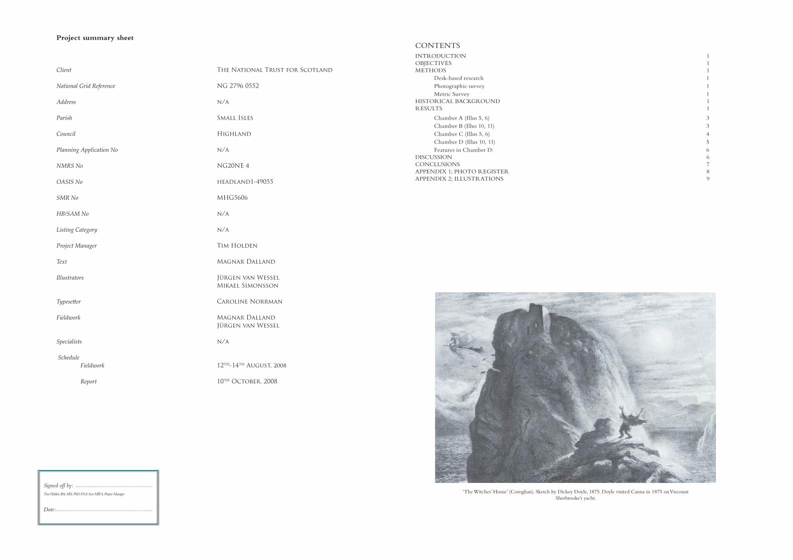
‘The Witches’ Home’ (Coroghan). Sketch by Dickey Doyle, 1875. Doyle visited Canna in 1875 on Viscount
Sherbrooke’s yacht.

Coroghan Castle, CannaCORO08
1
Historic Building Survey of Coroghan Castle, Canna
by Magnar Dalland
A Historic Building survey of the ruins of Coroghan Castle, Canna was carried out by Headland Archaeology Ltd from 12th to the 14th August
2008. The castle is owned by The National Trust for Scotland and is located at the E end of Canna, situated on the NW side of a stack some
25 m high that is otherwise surrounded by the sea.
The ruin is roofl ess and deteriorating. Large sections of the facing stones along the base of the outer walls are missing and a deep crack has opened
up in one of the walls. The survey was carried out to provide a basis for the National Trust in the planning of consolidation work to stabilise the
ruin, with structural advice being provided by Fairhurst, consulting, structural and civil engineers.
According to local tradition the building was a prison, used in the late seventeenth century by a jealous husband to confi ne his wife. However, the
location and design of the building clearly indicate that it was built as a defensive structure that turned the stack into a well defended position.
INTRODUCTION
This document reports on a Historic Building survey of the
ruins of Coroghan Castle, Canna carried out by Headland
Archaeology Ltd from 12th to the 14th August 2008. The
castle is located at the east end of Canna, situated on the NW
side of a stack some 25 m high that is otherwise surrounded
by the sea (Illus 1). The work was carried out in accordance
with a Written Scheme of Investigation prepared by Headland
Archaeology in line with the Project Outline provided by Jill
Harden and subsequent conversations.
The ruin is roofl ess; large sections of the facing stones along
the base of the outer walls are missing and a deep crack has
opened up in one of the walls, leaving the structure inherently
unstable.
OBJECTIVES
The objective of the work was to provide a measured and
photographic record of the castle supplemented by feature
descriptions and a basic written analysis. The survey is to be
used in preparing a methodology for consolidation of the
building, allowing the Trust or its agents to show Historic
Scotland how the consolidation work will aff ect the present
building.
METHODS
Desk-based research
In accordance with the WSI and Project Outline no desk-based
research was carried out as part of this project, as it is to be
undertaken by John Harrison under separate contract.
Photographic survey
A full photographic survey of the building and details of
interest were made using digital and colour slide SLRs. Each
photograph has been individually numbered and copied onto
a CD supplied with this report. Where possible, photos were
taken to enable the production of rectifi ed images of both the
internal and external elevations at a later date, if required.
However, due to the small size of the chambers some photos
had to be taken at such an oblique angle that it was not possible
to create a rectifi ed image of the entire elevation. In those cases
only the outline recorded through the REDM survey are
shown in the fi gures. Fortunately the elevations aff ected did
not contain any signifi cant details.
Metric Survey
Metric survey was undertaken through a combination of REDM
survey, hand survey, sketches and rectifi ed photography.
HISTORICAL BACKGROUND
The crag was mentioned as a ‘refuge’ in 1577-95, but with
no reference to a building it is assumed that the structure is
post-16th century (W G Collingwood 1906).
According to local tradition the building was a prison,
used in the late seventeenth century by a jealous husband to
confi ne his wife. Locally this tradition is associated with Donald
MacDonald of Clanranald and his wife Marion MacLeod.
Apart from this legend, very little is apparently known about
the building.
RESULTS
Although the structure is referred to as a castle, we have
chosen to refer to it as a building or structure in the report
due the uncertainty about its function and its diminutive size.
The term castle normally triggers associations to far more
impressive constructions.
The building is located on the side of a stack some 25 m
high and with a fl at sub-rectangular top 17 m long and 4 to
7 m wide. It is built across the only accessible route up to the
summit on the NW side of the stack and overlooking the
approach from the mainland (Illus 2).
The surviving portion of the building does not extend above
Canna Canna
Reproduced from 1976 Ordnance Survey 1:50,000 Landranger Series no 39, with the permission of the Controller of HMSO. © Crown copyright. Headland Archaeology Ltd, licence no AL 100013329 Reproduced from 1976 Ordnance Survey 1:50,000 Landranger Series no 39, with the permission of the Controller of HMSO. © Crown copyright. Headland Archaeology Ltd, licence no AL 100013329
© Crown Copyright, RCAHMS © Crown Copyright, RCAHMS
806500806500
805000805000
1280
0012
8000
1285
0012
8500
SiteSite
N
0 500 m
ARCHAEOLOGY (UK) Ltd
Illus 1Coroghan Castle, location plan

HEADLAND ARCHAEOLOGY (UK) LTD CORO08
2
the top of the stack and measures 4.4 m by 5.5 m with a rounded external corner to
the NW (Illus 3). Natural rock-faces have been incorporated into its structure to
form the walls to the S and E. The walls are up to 6 m high and built from mortared
random rubble. The outer and inner faces are faced by larger stones while the wall core
comprises smaller rubble. The outer walls vary in thickness from 0.8 m at the NW
corner down to 0.4 m above the entrance to the NE.
There are extensive scars at the base of the outer wall faces to the W and N where
the outer facing stones have been lost, exposing the wall core. This is likely to be one
of the reasons the building is becoming unstable.
The building is L shaped with a larger W wing aligned N to S and a smaller E wing.
The building appears to have been divided into at least four chambers (A-D), two on
the ground level (A and B) and two others (C and D) above on fi rst fl oor level.
0 5m
N
Ground floor
F1
F2
F3
F4
A
B
First floor
F21F22
F14
F13
F12
F11
F5
F15
C
D
F14
F2
F15F14
F2
F15
presentground surface
projectionof wall
bedrock
projection projectionof wall
see Illus 10for detail
0 2m
Key:
Opening
Exposed wall core
0 2m
Key:
Opening/beam socket
F6 F8F7 F9
F11F12
F13
F10
F1
angledcorner
turf coveredscarcement
present groundsurface
projectionof wall
projectionof wall
projectionof wall
bedrock
bedrock
Illus 2Castle on side of stack seen from NW
Illus 3Castle on side of stack seen from SW
Illus 4 & 5Ground and fi rst fl oor plan of building (left)
Chamber A and C. Internal N elevation (above)
Illus 6Chamber A and C. Internal W elevation

Coroghan Castle, CannaCORO08
3
Chamber A (Illus 5, 6)
Chamber A is located at ground fl oor level in the W part of the building. It is 2.4 m
long by 1.5 - 1.6 m wide. The NW corner is rounded refl ecting the form of the outer
wall face, while the other three corners are roughly square. The masonry that makes
up the rounded corner forms a small scarcement at the fi rst fl oor level (Illus 7). The E
half of the S wall comprises exposed bedrock; the remaining walls comprise mortared
random rubble with remains of harl pointing still surviving in some areas.
At the time of the survey the chamber had a fairly level ground surface, partly
covered in vegetation. No attempts were made to investigate its nature and it is likely
that the present surface is made up of accumulating soil that may cover the original
fl oor.
The chamber has no visible entrance and must have been accessed through a
trapdoor in the fl oor of Chamber C above. There are fi ve sockets in the W wall
indicating the position of the fl oor joists of the chamber above. If the current surface
represents the original fl oor level in the chamber it would only have been 1.45–1.55
m high.
There are three features in Chamber A (F01-F03):
F01 (Illus 8)
F01 is an opening located near the middle of the W wall. The opening is situated only
0.3 m above the current ground level. It measures 0.35 m wide by 0.46 m high at the
inner wall-face and has a stone lintel. The rough sill of the opening is level, while the
top of the opening is stepped down twice to reduce the height to some 0.27 m at the
outer wall-face. The sides of the opening are also stepped in and angled reducing the
width to 0.11 m on the outside. There are remains of harl pointing on the inside of
the opening.
F02 (Illus 9)
F02 is an opening in the W half of the N wall overlooking the approach to the
building. It is similar in size and position to F01, the feature being located close to the
original fl oor level at only 0.25 m above the current ground level. The opening has
an interior stone lintel and measures 0.28 – 0.33 m wide by 0.45 m high. The rough
sill of the opening is largely level while the top is stepped down reducing the height
to 0.35 m. The outer face of the wall has collapsed around the opening. There is harl
pointing across the rough sill of the opening.
F03
F03 is a sub-square void in the E wall. It is located approximately half-way along the
wall, and sits 1.2 m above the present ground level. The hole appears to be the socket
of a square beam as there are wood imprints in the mortar on the inside of the hole.
The beam may have protruded into the chamber about 0.35 m below the ceiling,
possibly forming the support for a ladder leading down into the chamber through a
trap door in the fl oor above. The hole continues through leading into beam sockets
on the other side of the wall.
Chamber B (Illus 10, 11)
Chamber B is located at ground fl oor level in the E wing and contains the main
entrance into the building. The chamber is defi ned by mortared stone walls to the N
and W. Remains of harl pointing still cover most of the W wall. The NW corner is
rounded, the curving masonry forming a scarcement in the corner at fi rst fl oor level
(Illus 12). The E side largely comprises bedrock with a small area in-fi lled with ma-
sonry next to the door to the N. There are no visible remains of the S wall at this level,
but the rising level suggest that chamber was no more than 1.3 to 1.5 m wide and 1.7
m long. Due to the steeply rising ground the height of the chamber varies
lintel
F14
F2
F21
F15
F4F4
F21
F22
F4F4
slot
presentground surface
rubble
projectionof wall
see Illus 5for detail
scarcementscarcement
bedrockexposed
wall core
projection projectionof wall
0 2m
Key:
Opening
Exposed wall core
Illus 8Opening F01 in the W wall of Chamber A
Illus 7Internal S-facing elevation of the W wing Chamber A.
Illus 9Opening F02 in the N wall of Chamber A Illus 10
Chamber B, D. Internal N elevation

HEADLAND ARCHAEOLOGY (UK) LTD CORO08
4
from 2.4 m at the entrance down to 1.4 m to 1.6 m under the S end of the fl oor of the
chamber above.
The chamber is partly fi lled with rubble including a fairly large block of collapsed
masonry located just inside the main entrance
The only feature in this chamber is the main doorway in the N wall (F04):
F04 (Illus 13)
The doorway into the building is 0.7 m wide and 1.85 m high with two stone steps
leading up to the door from the outside. The lintel comprises two wooden beams. The
outer beam is 1.1 m long, 0.19 m wide and 0.12 m thick. There is a 0.12 m wide and
0.04 m deep slot in the upper part of the beam indicating that the timber is re-used
from some other wooden structure.
The inner lintel appears also to be re-used timber as its W end has been worked. It
is 1.44 m long, 0.18 m wide and 0.12 m thick. There is a 0.07 m gap between the outer
an inner lintel. A 0.06 m deep and 0.22 m wide slot is cut into the inner beam above
the middle of the doorway forming a rectangular hole 0.22 m by 0.13 m up against the
outer beam. A rectangular slot in the inner wall face above the doorway corresponds
with the hole in the lintel below (Illus 14). A 1.1 m deep bar-hole is located on the W
side of the doorway.
Chamber C (Illus 5, 6)
Chamber C is situated above Chamber A in the W part of the building. It is 3.1 m
long by 2.0 m wide. All walls are built of mortared stone still partly covered by harl
pointing. The walls of the chamber survive up to a maximum height of 2.0 m, but
there seem to be no surviving parts of the original wall head. The doorway (F05) into
the chamber is located in the E wall at the SE corner.
At the NW corner of the chamber, there is a narrow scarcement at fl oor level
formed by the creation of a more angled internal corner in Chamber C compared with
the more rounded corner in the chamber below. Traces of this scarcement continue
all along the W wall level with the top of the fl oor joist slots. There is also a 0.7 m to
0.9 m wide scarcement at fl oor level that runs along the S wall of the chamber. The
scarcements to the E and S were covered in vegetation. It was therefore not possible to
see any details in their surfaces, but it seems clear that the scarcement along the E wall
is formed by the reduction of the wall thickness. The scarcement to the S appears to
F5
F17 F18 F19 F20F3
remains ofroof line
possiblecorbel
F4
0 2m
Key:
Opening
F5
F3
F16
remains ofroof line
line ofcrack
projectingmasonryprojectingmasonry
ridge ofharlingridge ofharling
projectionof wall
masonry
approximateposition ofdoorway
angledcorner
bedrock
bedrock
bedrock
rubble
ctionof
Illus 11, 12, 13 & 14Chamber B and D. Internal W elevation (top left)
Internal S-facing elevation of the E wing (bottom left)
Masonry to N of door F04 (above)
Door-opening F04 seen from the S (below)
Illus 15Vertical slot in wall with corresponding slot in wooden lintels above door opening.

Coroghan Castle, CannaCORO08
5
be largely formed by a cut into bedrock.
The fl oor level of the chamber is defi ned by the broad scarcements and fi ve sockets
(F06 – F10) for the fl oor joists in the W wall. The sockets indicate that the joists were
spaced out at around 0.5 m centre to centre (Illus 15).
There are a further fi ve features in the chamber comprising three openings in the
W wall (F11 – F13) and two openings towards the N (F14 – F15).
F05 (Illus 16)
The door opening leading into Chamber C is situated at the SE corner in the E wall. It
is 0.55 m wide and survives up to a height of 0.8 m. An 0.11 m wide and up to 0.10 m
deep vertical slot at the E end of the S wall indicates the position of the S door cheek.
The slot is D-shaped in cross section refl ecting the cross section of the door post. Only
a small part of the other side of the door opening survives, but also it shows traces of
the door cheek.
F06
F06 is a rectangular socket 0.21 m wide by 0.15 m high. It is located towards the SW
corner and is on the same level as the front edge of the scarcement along the S wall.
It is one of fi ve sockets that used to hold the fl oor joists in Chamber C. The socket is
lined with mortar that forms a cast of the joist. Today the socket is visible externally
as the outer wall-face has fallen away at this point.
F07
F07 is an oval socket 0.18 m wide by 0.16 m high to the N of F06. The shape of the
socket indicates that it held a sub-oval joist with a fl at upper surface. As with F06 to
the S the socket continues through the wall, but is likely to originally have been sealed
off on the outside.
F08
F08 is a rectangular socket 0.20 m wide by 0.13 m high to the N of F07. The form of
the socket indicates that it held a rectangular joist. The socket continues through to
the outer wall face, but a lip of mortar deep inside the hole indicates the original depth
of the socket that was originally sealed off on the outside.
F09
F09 is a D-shaped socket 0.19 m wide by 0.13 m high to the N of F08. As with the
three sockets to the S, the shape of the fl oor joist is preserved in the mortar lining the
socket. The socket is 0.27 m deep.
F10
F10 is a sub-rectangular socket 0.23 m wide by 0.12 m high. It is located 0.23 m to the
N of F09 and 0.2 m to the S of the NW corner. The shape of the socket indicates that
it held a rectangular fl oor joist that extended 0.18 m into the wall.
F11 (Illus 17)
F11 is a sub-rectangular opening located in the S half of the W wall. At the inner
wall-face it is 0.44 m high by 0.16 m wide capped by a stone lintel. The base of the
opening is level and is 0.9 m above the fl oor while the top of the opening is stepped
down twice to reduce the height to 0.26 m at the outer wall-face. The sides of the
opening are slanted inwards reducing the width to 0.16 m at the outside.
F12 (Illus 17)
F12 is a rectangular opening located near the middle of the W wall to the N of F11. It
is 0.40 m high by 0.26 to 0.31 m wide with a stone lintel. The opening is placed 0.2
m higher in the wall than F11 to the S with the base of the opening at 1.1 m above
the fl oor level. The top and base of the opening are roughly level, while its sides are
splayed reducing the width to 0.18 m on the outside.
F13 (Illus 17)
F13 is a small rectangular opening located in the N half of the W wall 0.46 m to the
N of F12. It measures 0.16 m wide by 0.20 m high and has a small stone lintel and a
similar sill. The sill is at the same height as F12 to the S at 1.1 m above the fl oor level.
The opening slants down at a 30 degree angle towards the outer wall face. As a result
the lintel on the outside lies 0.15 m below the sill on the inside.
F14 (Illus 18)
F14 is a rectangular opening located in the N wall at the NW corner of the chamber.
It is 0.24 m high by 0.17 m wide with a stone lintel. The opening is aligned towards
the NW and at right angles to the rounded corner. The base of the opening is 0.54
m above the fl oor level on the inside but slopes downwards towards the outer wall at
an angle of 16 degrees where it appears as a triangular opening 0.11 m high by 0.15
m wide.
F15 (Illus 18)
F15 is a rectangular opening located in the N wall near the NE corner of the chamber.
It is 0.24 m high by 0.17 m wide with a stone lintel. The base of the opening is at the
same level as F14 to the W but in contrast to F14 it slopes upwards towards the outer
wall-face at an angle of 15 degrees.
Chamber D (Illus 10, 11)
Chamber D is situated above Chamber B in the E part of the building. The E wall of
the chamber is missing and the only possible indication of the S wall is a small lump of
projecting masonry in the W wall possibly the remains of a corbel (Illus 19). A slight
vertical ridge extending 0.7 m down from the protruding masonry is in line with its N
side, but there are no traces of a corresponding ridge at its other side. The lack of any
remains of the proposed wall at the lower level seems to indicate that the protruding
Illus 16Five slots in the W wall for the fl oor joists of Chamber C
Illus 17 (left)Door F05 at the SE corner of Chamber C

HEADLAND ARCHAEOLOGY (UK) LTD CORO08
6
masonry is remains of a corbel used to support the roof, and that the entire S wall may
have been built out of wood. Assuming that the E wall of Chamber D was roughly
in line with the E wall of the chamber below, Chamber D was some 1.6 m long E to
W and 1.2 m wide.
As in the W part of the building, the NW corner of the upper chamber is less
rounded than the chamber below forming a small scarcement in the corner. The
scarcement continues around the inside of the N wall, only truncated by the slot in
the masonry above the door (see F04).
The fl oor level of the chamber is indicated by a slot (F16) in the W wall that
contains the imprints of the cross-sections of four fl oor joists (F17-20) that were
deeply imbedded into the wall. The top of the joists were level with the scarcement
in the NW corner of the chamber.. The fl oor level of Chamber D is 0.3 m below that
of Chamber C.
The two surviving walls of the chamber to the N and W are 1.5 m and 2.4 m high
respectively. The N wall survives up to its full height at its W end where it meets the
traces of the pitched roof-line of Chamber D visible on the outside of the E wall of
Chamber C (Illus 20). The roof-line has a downward pitch of 55 degrees towards the
N.
There are two openings in the N wall of the chamber (F21 – F22) overlooking the
approach to the building from the N side.
There were no surviving remains of any steps or doorway leading into the chamber,
but the only possible location of an access into this chamber seems to be in the
proposed timber S wall.
Features in Chamber D:
F16 (Illus 21)
F16 is a 1.12 m long, 0.2 m high and 0.6 m to 0.9 m deep slot in the W wall. The
slot was formed by the insertion of four wooden beams close to each other into the
wall. The beams were so close that the gaps between them were fi lled with mortar as
the wall was built up and over the joists, leaving behind imprints of their shape and
dimensions. The slot also contains the imprint of a fi fth beam (F03) that continued
straight through the wall into Chamber A. It is possible that this beam also was part
of the fl oor support in Chamber D
F17 (Illus 21)
F17 is the imprint of a rectangular wooden beam, 0.30 m wide by 0.14 m high at the
S end of the long beam slot. The socket extends 0.60 m into the wall. The projected
imprint of beam F03 lies immediately to the N of F17. There is no mortar surviving
between the two slots suggesting that the two beams were placed next to each other.
F18 (Illus 21)
F18 is the imprint of a rectangular wooden beam, 0.22 m wide by 0.16 m high to the
N of F03. The socket extends 0.70 m into the wall. A 0.05 m wide wall of mortar
separates the slot from F03 to the S.
F19 (Illus 21)
F19 is the imprint of a D-shaped wooden beam to the N of F18 that is 0.17 m wide by
0.16 m high and extends 0.77 m into the wall. A 0.08 m wide wall of mortar separates
the slot from F18 to the S.
F20 (Illus 21)
F20 is the imprint of a D-shaped wooden beam at the N end of the long beam slot. It
is 0.19 m wide by 0.16 m high and extends 0.90 m into the wall. A 0.03 m wide wall
of mortar separates the slot from F19 to the S.
F21 (Illus 22)
F21 is a square opening in the W half of the N wall. It measures 0.17 m by 0.17 m
and is located near NW corner and only 0.35 m above the fl oor of the chamber. The
opening slopes downwards towards the outer wall face at a 15 degree angle.
F22 (Illus 22)
F22 is a rectangular opening in the W half of the N wall. It is 0.16 m wide by 0.24 m
high and is located to the E of F21 some 0.80 m above the fl oor of the chamber.
DISCUSSION
Although large portions of the building are still extant, its original layout and func-
tion are diffi cult to resolve as it is a fairly unique structure in an unusual location.
However, its layout and setting can provide some clues to its function.
Local tradition suggests that the structure was built as a prison, and although it may
have functioned as a prison in the past, there are several features and aspects of this
building that indicate that this may not have been its original function.
The building has been constructed in a spectacular location on the very steep
sides of a small stack. The erection of a stone structure on near vertical slopes must
have created large problems during the construction phase even by today’s standards.
Considering the diffi culties creating stable foundations on such a steep slope it is
remarkable that the structure has survived up to the present.
There are two hollows on the top of the stack. These may be the remains of small
Illus 19Openings F14-15 in the N wall of Chamber C
Illus 20NW corner of Chamber D
Illus 21Traces of the pitched roof-line of Chamber D visible on the outer E wall of Chamber C
Illus 18Openings F11-13 in the W wall of Chamber C

Coroghan Castle, CannaCORO08
7
stone quarries used to provide some or all of the stone used for the construction of
the building. To have such a close source of building material would have been an
advantage given the diffi culties caused by the precarious location of the site.
The hollows are most likely to be quarries and not remains of buildings associ-
ated with the ‘Castle’ as the features comprise cuts into bedrock with no trace of any
associated wall remains.
The erection of this fairly small building eff ectively sealed off the only access to the
top of the stack. This seems to be the reason why it was decided to build it on the side
of the stack rather than on the top. By placing the building at this location the stack
was turned into a well defended position.
There are a total of nine openings in the building, excluding the two doorways.
These would all have let light into the chambers, but several have been constructed
in a way that indicates that they were built also to serve other functions. Three of the
openings (F13, 14 and 21) were built at a slant down through the wall that provided
an improved viewing angle of the approach to the building. A further three openings
(F1, 2 and 11) had a top that sloped downwards through the wall that also improved
the viewing angle.
Four of the openings (F1, 2, 11 and 12) had a much smaller aperture on the outside
which may suggest that they were built also to function as gun loops. F1 and F2 were
located some 0.3 m above the fl oor suitable for a lying down shooting position, the
other two that were located 0.9 m and 1.1 m above the fl oor indicate a kneeling or
crouched shooting position.
Opening F15 is diff erent from all the others as it slopes upwards through the wall.
This renders it fairly useless for observation or fi ring. One reason for its incline might
be that it served as a primitive chimney. There were no traces of any fi replaces in the
chamber, but this could have been heated using a brazier situated up against the wall
below the opening letting the smoke out. However there was no trace of soot on the
wall or inside the opening to support this suggestion.
The layout of the building appears to have been L-shaped. The W wing is aligned
NS and measures some 3 m by 5 m externally. The wing contains two fl oors,
Chamber A at ground level probably accessed through a trap door, and the larger
Chamber C at fi rst fl oor level accessed through a door at the SE corner. The door
threshold lies some 0.4 to 0.8 m above the sloping ground to the E. There were no
indication of any stone steps leading up to the door that would probably been accessed
by wooden steps or a small ladder.
Imprints of the fi ve wooden fl oor joists are still clearly visible in the W wall. The
two chambers are fairly small measuring 3.7 m2 and 6.2 m2 respectively. None of the
walls in the W wing are preserved up to their original wall head, but it seems likely
that the surviving remains are close to their original height. Since the wall heads are
not surviving it is not clear how the roof was pitched.
The E wing is smaller, aligned E-W and measures some 3 m by 2.5 m externally.
This part of the building is less well preserved. Given its poor preservation, there are
still several uncertainties concerning how the E wing was laid out and functioned.
The N wall is fully integrated with that of the W wing but curves slightly round
towards the SE hugging the side of the stack. The E wall of the wing has collapsed
leaving a jagged scar at the E end of the N wall. Very little of the S wall of the wing is
preserved which may indicate that it was made of wood.
The E wing contained the entrance into the building. There were no traces of
any doorframe or hinges in the masonry at the opening suggesting that the opening
had contained a door. It is possible that a door frame was attached to the masonry
using pegs hammered into gaps in the masonry, but here were no clear indications
of this and it would not provide a very secure fi xing of the door to its opening.
However, there was a slot in the inner wall face above the door extending down to a
corresponding slot in the wooden lintels above the door suggesting that the opening
and a possible door was blocked by lowering a thick wooden beam from above. A deep
slot in the masonry on the W side of the door may have held a second wooden beam
that would have secured this beam horizontally.
The E wing appears to have contained two compartments, Chamber B at the
entrance at ground level with Chamber D above. There were no visible traces of the
south wall of Chamber B. The faint traces of the S wall seen in the wall harl pointing
of the chamber above stops on top of the S fl oor joist, left no trace in the harl pointing
of the W wall below. The S wall of this chamber was no more than 1.5 m wide. The
access to the rest of the building must have been through this wall. Assuming a door
was situated in the middle of this wall, it would occupy approximately half of the wall
width leaving less than 0.4 m of walling on either side. It is possible that this side of
the chamber was left open, leaving a gap some 1.5 m wide by 1.45 m high at the S end
of the chamber. Due to the steeply sloping ground level, the height of the chamber
decreases from 2.4 m at the entrance down to a clearing of 1.45 m below the fl oor joist
at the S end of the chamber above.
Chamber D was situated on the fi rst fl oor in the E wing. It measured some 1.2 by
1.6 m, less than 2 m2 of fl oor space. The fl oor of the chamber appears to have been
made from four, possibly fi ve fl oor joists set next to each other. The W ends of the
joists were deeply embedded into the E wall of the W wing which could indicate that
they were cantilevered with little or no support in the opposite wall. The north wall
of the chamber survives to its original height at the NW corner as indicated by the
traces of the pitched roof-line in the adjacent wall.
The protruding masonry in the W wall could possibly be the remains of a corbel
that would have supported a small roof above the chamber. Assuming the pitch of the
Illus 22Slot F16, with imprints of fl oor joists F03, F17-20 in the W wall of Chamber D
Illus 23Openings F21 and F22 in the N wall of Chamber D
S side of the roof was the same as the N side the ridge of the roof would have been
roughly level with the top of the highest surviving part of the W wing.
The intermittent vertical ridge in the W wall in line with the N side of the
presumed corbel might refl ect the position of a light wooden S wall resting on fl oor
joist F17 at the S end of the beam slot F16.
The size of the chamber seems to suggest that it was meant to function as a
fi ghting platform possibly accessed by a ladder from the S. The two holes in the N
wall may have been gun loops for defending the steep path leading up to the entrance.
If by any chance the attackers made it through the entrance they would then been
facing the choice of either scramble backwards up a steep slope to face the defenders
on the platform above or to emerge from underneath the platform with their back to
the defenders while being attacked from above and behind.
CONCLUSIONS
The location and design of the building clearly indicate that it was built as a defensive
structure. A small building placed in a strategic location turned the stack into a very
defensible position. It was located in a relatively sheltered position on the side of the
stack with only the roof of the west wing protruding above its top.

HEADLAND ARCHAEOLOGY (UK) LTD CORO08
8
APPENDIX 1; PHOTO REGISTER
Pic no File name prefi x (jpg)
Slide From Details
1 CORO08-Pic01- SE Coroghan Castle.The surrounding landscape
seen from the sea.
2 CORO08-Pic02- 1 SW Castle on side of stack seen from SW
3 CORO08-Pic03- W Castle on side of stack seen from W
4 CORO08-Pic04- NW Castle on side of stack seen from NW
5 CORO08-Pic05- 2 N Castle on side of stack seen from N
6 CORO08-Pic06- 1 W External W-facing elevation
7 CORO08-Pic07- W External W-facing elevation, zoomed out
8 CORO08-Pic08- NW Path leading up to the entrance
9 CORO08-Pic09- NW NW corner and external W-facing elevation
10 CORO08-Pic10- NW NW corner and external N-facing elevation
11 CORO08-Pic11- NW Castle seen from the NW
12 CORO08-Pic12- NW Castle seen from the NW, zoomed out
13 CORO08-Pic13- 4 N External W-facing elevation
14 CORO08-Pic14- N External W-facing elevation
15 CORO08-Pic15- 1 SE External E-facing elevation of the W wing
16 CORO08-Pic16- SE External E-facing elevation of the W wing,
lower part
17 CORO08-Pic17- 1 SE Internal S-facing elevation of the E wing
18 CORO08-Pic18- S Internal NW corner of the E wing
19 CORO08-Pic19- S Door-opening F04 seen from the S
20 CORO08-Pic20- SE W side of door opening F04 with slot for
horizontal bar
21 CORO08-Pic21- 1 S Vertical slot in wall with corresponding slot in
wooden lintels above the door opening F04
22 CORO08-Pic22- 1 S Internal E wall face in Chamber B next to door
opening
23 CORO08-Pic23- SE Internal NE comer of Chamber D
24 CORO08-Pic24- SE Internal W wall in Chamber D
25 CORO08-Pic25- S Internal N wall in Chamber D
26 CORO08-Pic26- 1 E Chamber D. Slot F16, with imprints of fl oor
joists F03, F17-20
27 CORO08-Pic27- 1 S Chamber D. Openings F21 and F22 in the N
wall. Gun loops?
28 CORO08-Pic28- 1 S Internal S-facing elevation of the W wing
29 CORO08-Pic29- S W wing of the building seen from the S
30 CORO08-Pic30- S Internal ledge along the E side of the W wing
31 CORO08-Pic31- S Internal ledge along the W side of the W wing
32 CORO08-Pic32- E Chamber A. W wall of with opening F01 near
the base and the fi ve slots F 06 - F10 for the
fl oor joists of Chamber C above
33 CORO08-Pic33- S Chamber A. N wall with opening F02 near the
base
34 CORO08-Pic34- SW Chamber A. N part of the E wall with opening
F03 near the top
35 CORO08-Pic35- SW Chamber A. S part of the E wall
36 CORO08-Pic36- 1 Chamber A. E wall with opening F03 near the
top. Opening F02 in N wall to the left.
37 CORO08-Pic37- 1 N Chamber A. S wall
38 CORO08-Pic38- S Chamber A. Upper part of N wall with ledges
to the E and W
39 CORO08-Pic39- 1 E Chamber A. Detail of opening F01 in the W
wall
40 CORO08-Pic40- 1 S Chamber A. Detail of opening F02 in the N
wall
Pic no File name prefi x (jpg)
Slide From Details
41 CORO08-Pic41- 1 W Chamber A. Detail of opening F03 in the E wall
42 CORO08-Pic42- 1 E Chamber C. Openings F11-13 in the W wall.
43 CORO08-Pic43- 1 E Chamber C. Openings F11-13 and fl oor sockets
F7-10 in the W wall.
44 CORO08-Pic44- 1 SE Chamber C. Openings F12-14 and fl oor sockets
F7-10 in the W wall.
45 CORO08-Pic45- E Chamber C. Openings F11-14 in the W wall
46 CORO08-Pic46- E Chamber C. Floor sockets F6-8 in the W wall.
47 CORO08-Pic47- SE Chamber C. Opening F14 in the NW corner
48 CORO08-Pic48- S Chamber C. Opening F15 in the N wall
49 CORO08-Pic49- 1 SW Chamber C. E wall
50 CORO08-Pic50- SW Chamber C. Upper part of E wall
51 CORO08-Pic51- SW Chamber C. Lower part of E wall
52 CORO08-Pic52- SW Chamber C. Lower part of E wall with N side
of door F05
53 CORO08-Pic53- E Chamber C. Door F05 leading into SE corner
of Chamber
54 CORO08-Pic54- NW Chamber C. E end of S wall with S side of door
F05
55 CORO08-Pic55- 1 N Chamber C. S wall
56 CORO08-Pic56- N Chamber C. Upper middle section of S wall
57 CORO08-Pic57- N Chamber C. Upper W part of S wall
58 CORO08-Pic58- N Chamber C. Lower middle section of S wall
59 CORO08-Pic59- N Chamber C. Lower W part of S wall
60 CORO08-Pic60- S Chamber C. Openings F14 and F15 in the N
wall
61 CORO08-Pic61- 1 E Chamber C. Detail of fl oor socket F06 in the
W wall.
62 CORO08-Pic62- 1 E Chamber C. Detail of fl oor socket F07 in the
W wall.
63 CORO08-Pic63- 1 E Chamber C. Detail of fl oor socket F08 in the
W wall.
64 CORO08-Pic64- 1 E Chamber C. Detail of fl oor socket F09 in the
W wall.
65 CORO08-Pic65- 1 E Chamber C. Detail of fl oor socket F10 in the
W wall.
66 CORO08-Pic66- 1 S Chamber C. Detail of opening F14 at the NW
corner
67 CORO08-Pic66- 1 S Chamber C. Detail of opening F15 in the N
wall

9
Coroghan Castle, CannaCORO08
APPENDIX 2; ILLUSTRATIONS
Key:
Drawn by:JvW
13 Jane streetEdinburghEH6 5HE
Surveyed by:MD, JvW
Drawn date:29/09/2008
Surveyed date:14/08/2008
phone 0131 467 7705fax 0131 467 7706
Project code:CORO08
Scale:1:50 @ A3
Title:
Coroghon Castle, Canna
Plans
HISTORIC BUILDINGRECORDING
Masonry
Lower levels
Indicative edge of bedrock
0 5m
N
Wallhead
Ground floor
F1
F2
F3
F4
First floor
F21F22
F14
F13
F12
F11
F5
F15
C
D
A
B

10
HEADLAND ARCHAEOLOGY (UK) LTD CORO08
Key:
Drawn by:JvW
13 Jane streetEdinburghEH6 5HE
Surveyed by:MD, JvW
Drawn date:29/09/2008
Surveyed date:14/08/2008
phone 0131 467 7705fax 0131 467 7706
Project code:CORO08
Scale:1:25 @ A3
Title:
Coroghon Castle, Canna
Rectified image of SW facing elevation
HISTORIC BUILDINGRECORDING
Opening
Indicative edge of bedrock
Edge of masonry/features
Bedrock
0 1m
Key:
Drawn by:JvW
13 Jane streetEdinburghEH6 5HE
Surveyed by:MD, JvW
Drawn date:29/09/2008
Surveyed date:14/08/2008
phone 0131 467 7705fax 0131 467 7706
Project code:CORO08
Scale:1:25 @ A3
Title:
Coroghon Castle, Canna
Rectified image ofSW facing elevation
HISTORIC BUILDINGRECORDING
Opening
Indicative edge of bedrock
Edge of masonry/features
Bedrock
0 1m
bedrock
bedrock
F1
F8 F7 F6
F11
F13F12
F1
F8 F7 F6
F11
F13F12
exposed wall core
exposed wall core

11
Coroghan Castle, CannaCORO08
Coroghan Castle, CannaCORO08
Drawn by:JvW
13 Jane streetEdinburghEH6 5HE
Surveyed by:MD, JvW
Drawn date:29/09/2008
Surveyed date:14/08/2008
phone 0131 467 7705fax 0131 467 7706
Project code:CORO08
Scale:1:25 @ A3
Title:
Coroghon Castle, Canna
Rectified image ofNW facing elevation
HISTORIC BUILDINGRECORDING
Opening
Indicative edge of bedrock
Edge of masonry/features
Bedrock
F21
F15
F14
F2
F22
F21
F15
F14
F2
F22
0 1m
Key:
exposed wall core
exposed wall core
F4F4
bedrockthreshold
bedrock
threshold
bedrock
12
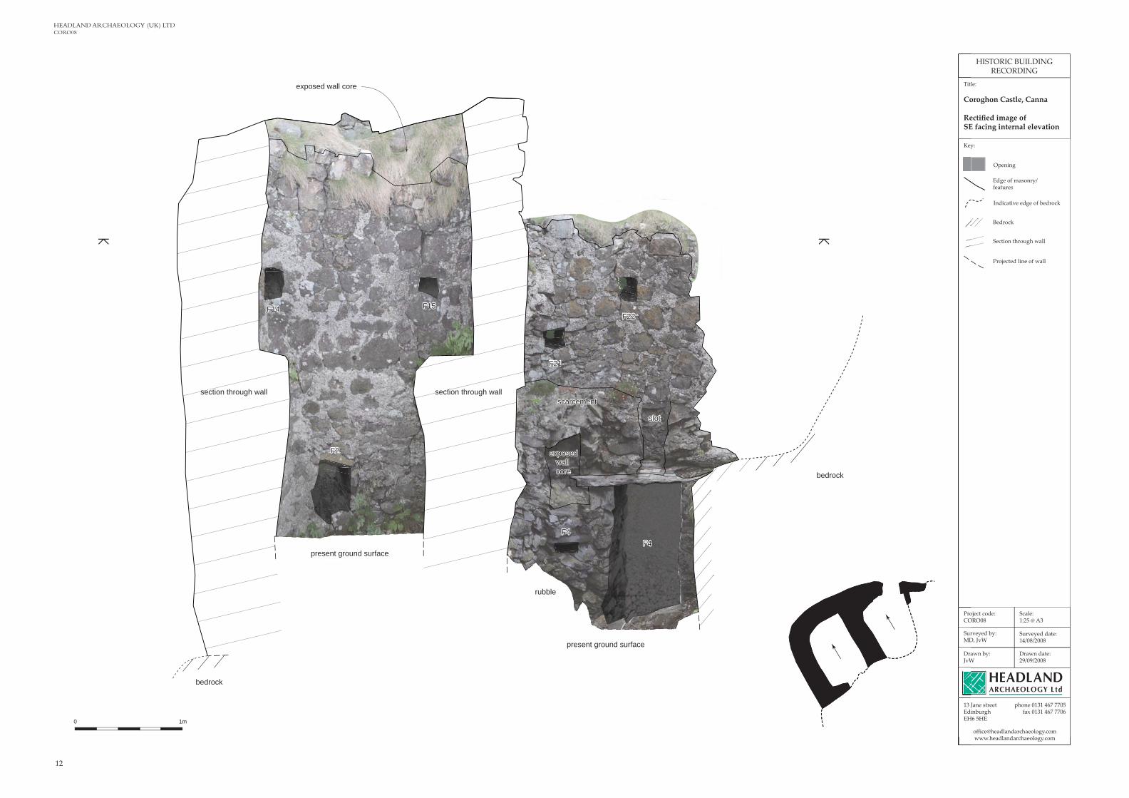
HEADLAND ARCHAEOLOGY (UK) LTD CORO08
Drawn by:JvW
13 Jane streetEdinburghEH6 5HE
Surveyed by:MD, JvW
Drawn date:29/09/2008
Surveyed date:14/08/2008
phone 0131 467 7705fax 0131 467 7706
Project code:CORO08
Scale:1:25 @ A3
Title:
Coroghon Castle, Canna
Rectified image ofSE facing internal elevation
HISTORIC BUILDINGRECORDING
Key:
Opening
Indicative edge of bedrock
Edge of masonry/features
Bedrock
Section through wall
Projected line of wall
0 1m
F14
F2
F21
F22F15
F4F4
F14
F2
F21
F22
F4F4
F15
exposed wall core
slot
present ground surface
present ground surface
rubble
section through wall section through wallscarcementscarcement
bedrock
exposedwall core
exposedwall core
bedrock
sectiosec

13
Coroghan Castle, CannaCORO08
Drawn by:JvW
13 Jane streetEdinburghEH6 5HE
Surveyed by:MD, JvW
Drawn date:29/09/2008
Surveyed date:14/08/2008
phone 0131 467 7705fax 0131 467 7706
Project code:CORO08
Scale:1:25 @ A3
Title:
Coroghon Castle, Canna
Rectified image of ChambersA and C NE facing internal elevation
HISTORIC BUILDINGRECORDING
Opening
Indicative edge of bedrock
Edge of masonry/features
Bedrock
Present ground surface
Section through wall
Projected line of wall
F6 F8F7 F9
F11
F12 F13
F10
F1
F6 F8F7 F9
F11
F12 F13
F10
F1
0 1m
Key:
angled corner
turf coveredscarcement
present ground surface
bedrock
bedrock
section through wall
section through wall
sectionthrough wall

14
HEADLAND ARCHAEOLOGY (UK) LTD CORO08
Drawn by:JvW
13 Jane streetEdinburghEH6 5HE
Surveyed by:MD, JvW
Drawn date:29/09/2008
Surveyed date:14/08/2008
phone 0131 467 7705fax 0131 467 7706
Project code:CORO08
Scale:1:25 @ A3
Title:
Coroghon Castle, Canna
Rectified image of ChambersB and D NE facing internalelevation
HISTORIC BUILDINGRECORDING
Key:
Opening/socket
Indicative edge of bedrock
Edge of masonry/features
Bedrock
Rubble
Section through wall
Projected line of wall
0 1m
F5
F17 F18 F19 F20F3
remains ofroof line
F5
F17 F18 F19 F20F3
remains ofroof line
line ofcrackline ofcrack
projectingmasonryprojectingmasonry
ridge ofharlingridge ofharling
masonry
approximateposition ofdoorway
angledcorner
bedrock
bedrock
bedrock
rubble
Projected lineof masonry
section through wall

15
Coroghan Castle, CannaCORO08
Key:
Drawn by:JvW
13 Jane streetEdinburghEH6 5HE
Surveyed by:MD, JvW
Drawn date:29/09/2008
Surveyed date:14/08/2008
phone 0131 467 7705fax 0131 467 7706
Project code:CORO08
Scale:1:25 @ A3
Title:
Coroghon Castle, Canna
SW facing internal elevationof Chambers A and C
HISTORIC BUILDINGRECORDING
Note:
The oblique nature of the photography of this elevation produced poor results during rectification and have been omitted.
Please see photos 29, 36 and 49 on the accompanying CD for details.
Opening
Indicative edge of bedrock
Edge of masonry/features
Bedrock
Present ground surface
Section through wall
Projected line of wall
turf covered scarcement
present ground surface
bedrock
bedrock
F3
0 1m
approximateposition ofdoorway
b
section through wallhrough
masonry
exposedwall core
exposedwall core

16
HEADLAND ARCHAEOLOGY (UK) LTD CORO08
Drawn by:JvW
13 Jane streetEdinburghEH6 5HE
Surveyed by:MD, JvW
Drawn date:29/09/2008
Surveyed date:14/08/2008
phone 0131 467 7705fax 0131 467 7706
Project code:CORO08
Scale:1:25 @ A3
Title:
Coroghon Castle, Canna
Rectified image of ChambersA and C NW facing internal elevation
HISTORIC BUILDINGRECORDING
Opening
Indicative edge of bedrock
Edge of masonry/features
Bedrock
Section through wall
Projected line of wall
0 1m
turf coveredscarcement
bedrock
masonrymasonry
masonrymasonry
bedrock
bedrock
section through wall