HiQuad - Istituto Nazionale di Fisica Nucleare
48
Operating Instructions incl. Declaration of Conformity BG 5400 BE (2004-12) 1 HiQuad Quadrupole Mass Spectrometry System QMG 700
Transcript of HiQuad - Istituto Nazionale di Fisica Nucleare

Operating Instructions incl. Declaration of Conformity
BG 5400 BE (2004-12) 1
HiQuad Quadrupole Mass Spectrometry System
QMG 700
2 BG 5400 BE (2004-12) QMG 700.oi
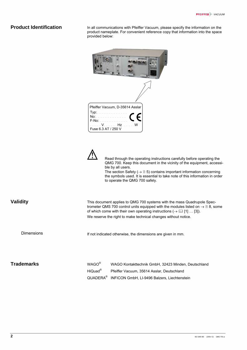
In all communications with Pfeiffer Vacuum, please specify the information on the product nameplate. For convenient reference copy that information into the space provided below:
Typ:No: F-No: V Hz WFuse 6.3 AT / 250 V
Pfeiffer Vacuum, D-35614 Asslar
Read through the operating instructions carefully before operating the QMG 700. Keep this document in the vicinity of the equipment, accessi-ble by all users. The section Safety (→ 5) contains important information concerning the symbols used. It is essential to take note of this information in order to operate the QMG 700 safely.
This document applies to QMG 700 systems with the mass Quadrupole Spec-trometer QMS 700 control units equipped with the modules listed on → 8, some of which come with their own operating instructions (→ [1] … [3]). We reserve the right to make technical changes without notice.
If not indicated otherwise, the dimensions are given in mm.
WAGO® WAGO Kontakttechnik GmbH, 32423 Minden, Deutschland
HiQuad® Pfeiffer Vacuum, 35614 Asslar, Deutschland
QUADERA® INFICON GmbH, LI-9496 Balzers, Liechtenstein
Product Identification
Validity
Dimensions
Trademarks

BG 5400 BE (2004-12) QMG 700.oi 3
Contents
Product Identification 2 Validity 2 Trademarks 2 Contents 3 1 Safety 5 1.1 Symbols Used 5 1.2 Intended Use 5 1.3 Safety Information 6 1.4 Liability and Warranty 6 1.5 Courses 6 2 System Overview 7 2.1 QMG 700 Quadrupole Mass Spectrometer, Components and Modules 8 2.1.1 Controller QMS 700 8 2.1.2 42x Components 10 3 Technical Data 11 3.1 General 11 3.2 System Chassis SC 700 11 3.3 Quadrupole Controller QC 700 13 3.3.1 Operation Modes and Parameters 13 3.3.2 Electrical Connections QC 700 15 3.4 Ion Supply IS 716 17 3.4.1 Potentials IS 716 18 3.4.2 Electrical Connections IS 716 20 3.5 High Voltage Supply HV 701 21 3.6 I/O System IO 700 22 3.7 Field Bus FB 711 24 3.8 Electrometer Preamplifier EP 422 25 3.9 Ion Counter Preamplifier CP 400 26 4 Installation 27 4.1 Overall System 27 4.2 Installation of the System Chassis 28 4.3 Installation/Replacement of Modules in the System Chassis 29 4.4 Installation of the Field Bus FB 711 30 4.5 EP 422 31 4.6 CP 400 32 4.7 QMH 4xx 32 4.8 QMA 4x0 32 4.9 System Wiring 33 4.10 PC Connection 36 4.11 IO 700 Wiring 37 4.12 Operation of Two and More Chassis (optional) 38

4 BG 5400 BE (2004-12) QMG 700.oi
5 Operation 39 5.1 Initial Start Up 39 6 Maintenance 40 6.1 Maintenance of the Air Filter 40 7 Repair 41 7.1 Replacing the Mains Fuse 41 8 Accessories 42 9 Storage 42 10 Returning the Product 42 11 Disposal 43 Appendix 44 A: Connection Diagram IO 700 44 B: Literature 45 Declaration of Contamination 46 Declaration of Conformity 47
For cross-references within this document, the symbol (→ XY) is used, for cross-references to further documents, the symbol (→ [Z]).

BG 5400 BE (2004-12) QMG 700.oi 5
1 Safety
DANGER
Information on preventing any kind of physical injury.
WARNING
Information on preventing extensive equipment and environmental damage.
Caution
Information on correct handling or use. Disregard can lead to malfunctions or mi-nor equipment damage.
Skilled personnel
All work described in this document may only be carried out by persons who have suitable technical training and the necessary experience or who have been instructed by the end-user of the product.
Consultation of operating instructions required (symbol printed on equipment housing).
Notice
Optical inspection
italic Labels on modules, keywords, variables etc.
The QMG 700 is a mass spectrometer designed for gas analysis in the high vacuum range. It may be used only for this purpose. The instructions in this user’s guide and in those of the accessories must be conscientiously followed.
DANGER
The QMG 700 is not intended to produce measurement results on which the safety of persons or large assets depend. For such applications the safety must be ensured by additional measures.
1.1 Symbols Used
1.2 Intended Use

6 BG 5400 BE (2004-12) QMG 700.oi
• Adhere to the applicable regulations and take the necessary precautions for the process media used.
• Before handling any used instruments or components, find out whether they are contaminated. Adhere to the relevant regulations and take the necessary pre-cautions when handling contaminated parts.
• Pass on the safety information to other users.
Pfeiffer Vacuum assumes no liability and the warranty becomes null and void if the custodian or third parties • disregard the information in this document • use the product in a non-conforming manner • make any kind of changes (modifications, alterations etc.) to the product • use the product with accessories not listed in the corresponding product docu-
mentation The custodian assumes the responsibility in conjunction with the process media used.
Courses
Pfeiffer Vacuum offers application, operating and maintenance courses for the best use of this product. Please inquire with your local Pfeiffer Vacuum partner.
1.3 Safety Information
1.4 Liability and Warranty
1.5 Courses

BG 5400 BE (2004-12) QMG 700.oi 7
2 System Overview
The QMG 700 comprises of the controller QMS 700 (system chassis SC 700 in-cluding the modules QC 700, FB 711, IS 716, HV 701 and IO 700). From the 42x system the modules RF generators (QMH 4xx-x), analyzers (QMA 4x0) the elec-trometer preamplifier (EP 422) and the ion counter preamplifier CP 400 are utilized as well.
The following block diagram shows the general QMG 700 system structure. De-pending on the application, various configurations are possible (→ [1] … [3]). For ion counting the electrometer preamplifier EP 422 is replaced by the ion counter preamplifier CP 400. Individual modules are described in detail on the following pages. The block diagram below shows a configuration example.
SEM or CD-SEM
QMA 4x0Ion source Mass filter
Faraday collector
Ion SupplyIS 716
High VoltageSupplyHV 701
PreampEP 422 (2)
PreampEP 422 (1)
Ion counterCP 400
Power supply(SC 700)
I/O SystemIO 700
QMS 700
Field BusFB 711(Option)
QuadrupoleControllerQC 700
Field bus
PC
PC link(Ethernet / USB)
DI AI DO AO BusIN
BusOut
MainsAC
(90° ion deflec-tion unit)1)
RF generatorQMH 4xx
System components
System structure QMG 700
8 BG 5400 BE (2004-12) QMG 700.oi
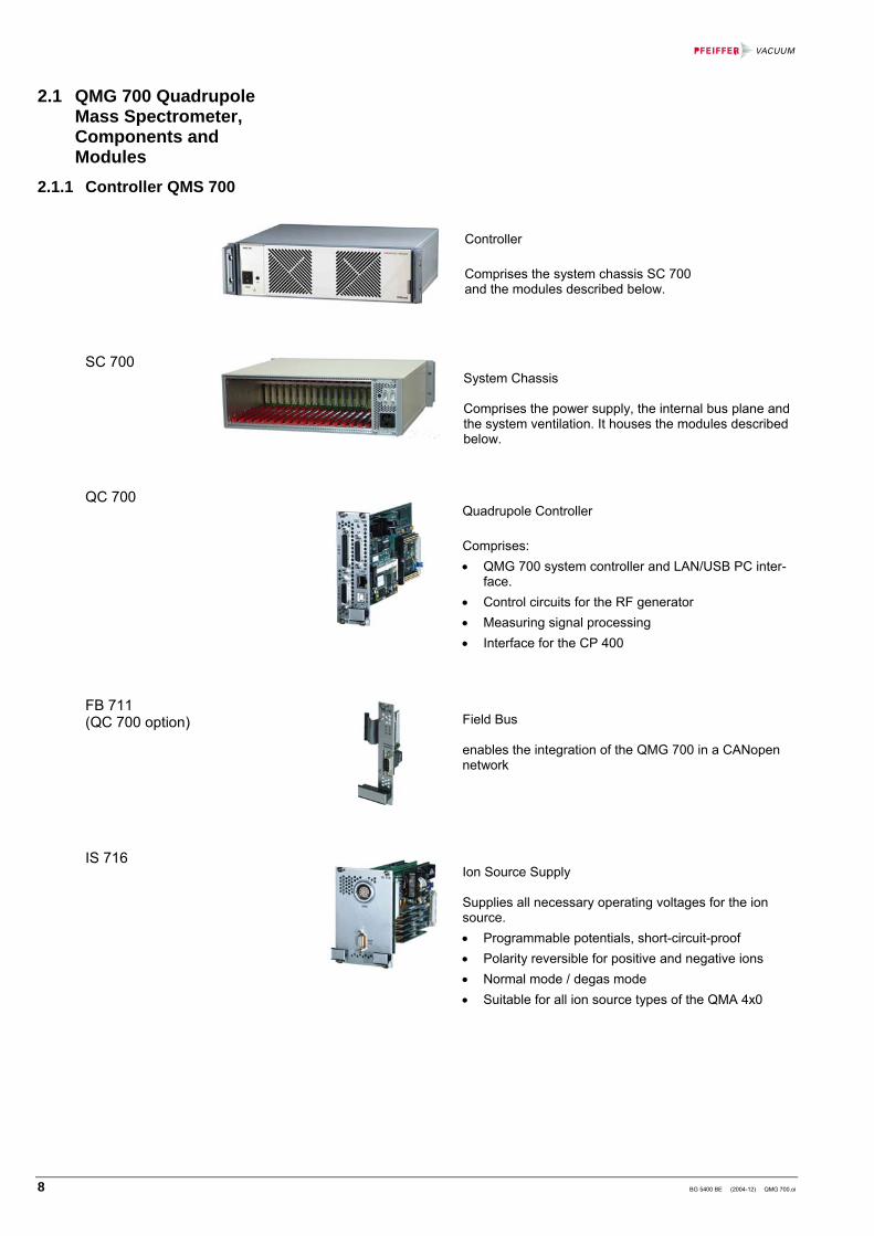
Controller Comprises the system chassis SC 700 and the modules described below.
System Chassis Comprises the power supply, the internal bus plane and the system ventilation. It houses the modules described below.
Quadrupole Controller Comprises: • QMG 700 system controller and LAN/USB PC inter-
face. • Control circuits for the RF generator • Measuring signal processing • Interface for the CP 400
Field Bus enables the integration of the QMG 700 in a CANopen network
Ion Source Supply Supplies all necessary operating voltages for the ion source. • Programmable potentials, short-circuit-proof • Polarity reversible for positive and negative ions • Normal mode / degas mode • Suitable for all ion source types of the QMA 4x0
2.1 QMG 700 Quadrupole Mass Spectrometer, Components and Modules
2.1.1 Controller QMS 700
SC 700
QC 700
FB 711 (QC 700 option)
IS 716

BG 5400 BE (2004-12) QMG 700.oi 9
High Voltage Supply Supplies high voltage to the SEM 217 for positive ion detection.
I/O System Provides programmable digital and analog inputs and outputs.
HV 701
IO 700

10 BG 5400 BE (2004-12) QMG 700.oi
42x components have initially been designed for the QMG 420/421 and QMG 422 system, however they are fully compatible to the QMG 700 system.
Electrometer Preamplifier The EP 422 amplifies the very small ion current signals of the analyzer to voltage levels that are suitable for further processing. It is installed directly on the analyzer in order to minimize parasitic noise. • Compact, simple installation on QMA 4x0 • Low-noise, low-drift, little vibration sensitivity • Fast response and quick recovery form overdriving
On analyzers with 90°off-axis SEM, two EP 422 can be connected. This allows simple changeover from Faraday to SEM mode (→ 33 and
[2]).
Ion Counter Preamplifier comprises the pulse coupling, amplifier and pulse height discriminator with adjustable threshold. It is installed directly on the QMA 4x0 with 90°off-axis SEM (separate operating instructions → [3]).
RF-Generator produces the high frequency voltage required for mass separation (separate operating instructions → [1]). QMH type Range QMA type Rod ø QMH 400-1 128 amu QMA 410 16 mm QMH 400-5 300 amu QMA 430 8 mm QMH 400-5 512 amu QMA 400 8 mm QMH 410-1 1024 amu QMA 400 8 mm QMH 410-2 2048 amu QMA 400 8 mm QMH 410-3 340 amu QMA 410 16 mm QMH 402-2 16 amu QMA 410 16 mm
In the following QMH 4xx or QMA 4x0 always refers to all types if not specified otherwise.
Analyzer Comprises the ion source, mass filter, ion collector and housing (separate operating instructions → [1]). Ion collector types: • Faraday collector • SEM 217 (90° off-axis with integrated Faraday
collector).
2.1.2 42x Components
EP 422
CP 400
QMH 4xx
QMA 4x0

BG 5400 BE (2004-12) QMG 700.oi 11
3 Technical Data
This information applies to all QMS 700 modules unless specified otherwise.
Temperature Storage Operation
–40 °C … +65 ° +5 °C … +40 °C
Relative humidity ≤80% up to +31 °C, decreasing linearly to 50% at +40 °C
Use indoors, altitude up to 2000 m NN Type of protection IP 30 Overvoltage category II
Pollution degree 2
Mains switch Power
LED DC
Filter cover
Module slots
Mains connector Fuse holder
Mains connection Mains voltage Power requirement Connector
100 … 240 VAC, 50 … 60 Hz ≤500 W mains connector with integrated fuse holder
Fuse 6.3 AT HBC, 5×20 mm Mains cable country specific
7.5 kg (without modules)
18 (4U each)
3.1 General Ambient conditions
3.2 System Chassis SC 700 Front panel
Rear panel
Power supply
Dimensions [mm]
Weight
Module slots

12 BG 5400 BE (2004-12) QMG 700.oi
In order to expand system functionality, up to four SC 700 chassis can be cas-caded (→ 38) 1).
Two versions of the SC 700 chassis are available:
• Standard system chassis (operated as a single chassis).
BUS IN, BUS OUT and 24 VDC power supply connectors are not equipped on this version.
• System chassis with the expansion option (up to four chassis can be operated on a bus, interconnection between chassis is made via bus cable 1).
• Module arrangement in chassis No. 2 … 4 differs from chassis No. 1 (→ 38).
SC 700 chassis No. 3
HV 701or
IS 716
SC 700 chassis No. 1(Master)
QC 700
SC 700 chassis No. 2
HV 701or
IS 716
SC 700 chassis No. 4
HV 701or
IS 716
BUS IN ( D-Sub,9 pins, male)
BUS OUT(D-Sub,9 pins, male)
24 VDCpower supply
SC 700
CAN termination
CAN termination
Connector for optional chassis expansion, must be terminated with a resistor if not used.
Connector for optional chassis expansion, must be terminated with a resistor if not used.
This 24 V supply may only be used for an external bus node. Do not use it for any other purpose.
4
3 1
Connector type: M8, female
Pin Signal Comment
1 +24 V Imax. 2 A 3 0 V 4 Not connected
1) Chassis version with the expansion option are configured in the factory and will be delivered with an additional set of documents.
System expansion
BUS IN
BUS OUT
24 VDC power supply

BG 5400 BE (2004-12) QMG 700.oi 13
QMH Connector for RF generator (QMH 4xx) CTRL Connector for test-, monitor and special purpose signals
CP Connector for ion counter preamplifier (CP 400) LAN Ethernet interface- (PC) with integrated status LEDs USB USB interface (PC)
General Compatibility system chassis SC 700 Number of slots occupied 2 Modules per system 1 Slot No. 1 and 2
(lefthand side of system chassis, → 29) Weight 0.4 kg
Number of measuring channels
128
Operation modes MONO- / MULTI channel Measuring cycles 1 ... 10'000 or REPEAT Time required for a channel change
100 ... 200 µs (at min. PAUSE in Cycle)
mass-MODE Measuring methode SCAN-N SCAN-F STAIR
SAMPLE PEAK-L PEAK-F
ADJUST-C ADJUST-F
Analogscan normal Analogscan with FIR filter for measuring value Scan Bargraph in steps of 1 amu Single mass and MID (Multiple Ion Detection) Scan Bargraph using level criterion Scan Bargraph using FIR FILTER Coarse search Fine search
3.3 Quadrupole Controller QC 700
3.3.1 Operation Modes and Parameters
Mass scan modes

14 BG 5400 BE (2004-12) QMG 700.oi
STEPS per mass Scan-SPEED FIX-
Range AUTO-Range
125 µs/amu 8/amu ---
250 µs/amu 16/amu --- 0.5 … 1 ms/amu 32/amu 1)
--- 2 … 20 ms/amu 64/amu 1) 32/amu 1)
50 ms/u ...60 s/amu 64/amu 1) 64/amu 1)
1) 32 at mass range 2048
16 at mass range 4096
EP 422 or external inputs Ion counter (CP 400) mass-MODE FIX-Range AUTO-Range AUTO-Range
SAMPLE 125µs … 60 s 0.5 ms … 60 s 125µs … 60 s
STAIR 125µs/amu … 60 s/amu 2 ms/amu … 60 s/amu 0.5 ms/amu … 60 s/amu
SCAN 125µs/amu … 60 s/amu 5 ms/amu … 60 s/amu 1.25 ms/amu … 60 s/amu
PEAK 125µs/amu … 60 s/amu 5 ms/amu … 60 s/amu 1.25 ms/amu … 60 s/amu
detect-TYPE
FARAD Faraday collector, EP 422 SEM SEM (type configurable), EP 422
ION-CNT ion counter CP 400 EXTERN 1 external analog input of QC 700 (EXT IN 1) EXTERN 2 external analog input of QC 700 (EXT IN 2)
A-INPUT (1 … n) analog signal via IO 700 (analog channels 1 … n)
Detector type Measurement ranges
Modes Resolution
FARAD,SEM 10-12 … 10-5 A fsd FIX- and AUTO-Range
16 bit 2) (per range)
EXTERN GAIN 1: ±10.240 VGAIN 10: ±1.024 V
FIX-Range 16 bit 2)
ION-CNT 10-2 … 108 cps (meaningful use up to 106 … 107 cps)
AUTO-Range in mass-MODE: SAMPLE: 1 / DWELL STAIR: 2 / SPEED SCAN: steps / SPEED
2) Further increased by averaging
Mass scale resolution
Measurement speeds
Detector
Measurement ranges and resolution

BG 5400 BE (2004-12) QMG 700.oi 15
Filter type two stage low pass effective for preamp and external inputs
Filter time constant automatic or selectable in 9 steps: 5, 18, 85, 400 µs 1.7, 8, 40, 180, 800 ms
Filter step response
τ63
ts τ63: filter time constant
settling time to ±1‰: ts ≈4 × τ63
NORMAL (N) Low pass (average value) FIR (F) Finite Impulse Response
Connector for RF generators (QMH 4xx) (D-Sub 25 pin, female).
Ethernet connector (RJ45) (PC connector → 36).
The interface status is indicated by two LEDs integrated in the RJ45 connector:
LED Status Meaning lit data transfer rate
100 MHz Green
dark data transfer rate 10 MHz
lit (flickering)
data transfer in progress
dark no data transfer (or no connection)
GreenRJ45
Yellow
yellow
USB PC connector (→ 36).
USB connector type B
Analog filter
Digital filter
3.3.2 Electrical Connections QC 700 QMH connection
LAN connection
USB connection

16 BG 5400 BE (2004-12) QMG 700.oi
Pin Signal Signal type Description 1 GND GND via 100 Ω to GND 10 GND GND via 100 Ω to GND 26 GND GND via 100 Ω to GND 2 RUN IN TTL input input for external start of measuring cycle, low true,
internal pull-up 5.6 kΩ to +5 V 14 SYNC IN TTL input reserved for future use, low true,
internal pull-up 5.6 kΩ to +5 V 15 IN 0 TTL input internal pull-up 5.6 kΩ to +5 V (can only be used if
jumper J2 is in place) 3 IN 1 TTL input internal pull-up 5.6 kΩ to +5 V (can only be used if
jumper J4 is in place) 16 IN 2 TTL input internal pull-up 5.6 kΩ to +5 V 23 OUT 0 TTL output 11 OUT 1 TTL output 25 SYNC
OUT+ TTL output positive edge marking start of measurement,
scope trigger 13 SYNC OUT- GND referece point SYNC OUT+,via 200 Ω to GND 4 EXT IN 1+ analog input 17 EXT IN 1– analog input
terminals for external voltmeter (differentially), max. ±10 V, with low pass filter/amplifier
5 EXT IN 2+ analog input 18 EXT IN 2– analog input
terminals for external voltmeter (differentially), max. ±10 V, with or without low pass filter/amplifier
6 ELM OUT+ analog output output of low pass filter/amplifier, ±10 V, max 0.1 mA via 200 Ω
19 ELM OUT– GND referece point for ELM OUT+, via 200 Ω to GND 7 AO MON 0+ analog output user configurable output 1), ±10 V, 12 Bit,
max. 0.1mA via 200 Ω 20 AO MON 0– GND referece point for AO MON 0+, via 200 Ω to GND 8 AO MON 1+ analog output user configurable output 2), ±10 V, 12 Bit,
max. 0.1 mA, via 200 Ω 21 AO MON 1– GND referece point for AO MON 1+ via 200 Ω to GND 9 SCO+ analog output output "mass number", 0 … +10 V, 16 Bit,
max. 0.1 mA, via 200 Ω 22 SCO– GND referece point for SCO+, via 200 Ω to GND 12 EP OUT+ analog output electrometer signal, max. 0.1 mA, via 200 Ω 24 EP OUT– GND referece point for EP OUT+, viar 200 Ω to GND
1) Reserved for Range Code of detector in monitor mode:
Detector range Output voltage
1×10⁻⁵ A 8 V
1×10⁻⁶ A 7 V
1×10⁻⁷ A 6 V
1×10⁻⁸ A 5 V
1×10⁻⁹ A 4 V
1×10⁻¹⁰ A 3 V
1×10-11 A 2 V
1×10-12 A 1 V
(In ion counter mode, the output voltage is 0 V) 2) Reserved for intensity signal in monitor mode (various configurations are possible):
• Linear (±10 V / decade)
• Logarithmic (±10 V FS, 1 … 10 decades)
CTRL connector, pin assignment
1
9
10
18
19
26
HD-Sub, 26 pins
View on QC 700

BG 5400 BE (2004-12) QMG 700.oi 17
QMA Connector for analyzer
AUX I/O Connector for filament pro-tection and reserved I/Os
General Compatibility system chassis SC 700 Number of slots occupied 4 Modules per system max. 2 Slot No. (→ 29) Weight 1 kg Filament power supply Voltage 0 … +10 V Current max. 5 A Power max. 50 W Operation modes Fil 1, Fil 2 Filament protection 0 … 5 A Emission Normal 0 … 10 mA Degas 0 … 20 mA
3.4 Ion Supply IS 716
18 BG 5400 BE (2004-12) QMG 700.oi
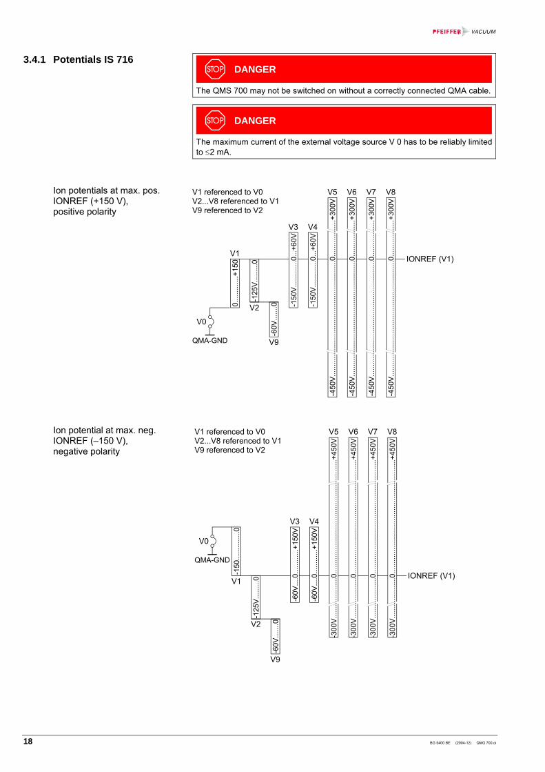
DANGER
The QMS 700 may not be switched on without a correctly connected QMA cable.
DANGER
The maximum current of the external voltage source V 0 has to be reliably limited to ≤2 mA.
0....
......
...+1
50
-125
V....
.....0
-150
V....
......
...0.
..+60
V
-60V
......
.0 -150
V....
......
...0.
..+60
V
-450
V....
......
......
......
......
......
......
......
......
.....0
......
......
......
+300
V
-450
V....
......
......
......
......
......
......
......
......
.....0
......
......
......
+300
V
-450
V....
......
......
......
......
......
......
......
......
.....0
......
......
......
+300
V
-450
V....
......
......
......
......
......
......
......
......
.....0
......
......
......
+300
V
V1
V9
V3 V4
V5 V6 V7 V8
V2
V0
QMA-GND
IONREF (V1)
V1 referenced to V0V2...V8 referenced to V1V9 referenced to V2
-150
......
......
..0
-125
V....
.....0
-60V
......
.0
-60V
....0
......
......
+150
V
-300
V....
......
......
....0
......
......
......
......
......
......
......
......
......
..+45
0V
V1
V9
V3 V4
V5 V6 V7 V8
V2
V0
QMA-GND
IONREF (V1)
V1 referenced to V0V2...V8 referenced to V1V9 referenced to V2
-300
V....
......
......
....0
......
......
......
......
......
......
......
......
......
..+45
0V
-300
V....
......
......
....0
......
......
......
......
......
......
......
......
......
..+45
0V
-300
V....
......
......
....0
......
......
......
......
......
......
......
......
......
..+45
0V
-60V
....0
......
......
+150
V
3.4.1 Potentials IS 716
Ion potentials at max. pos. IONREF (+150 V), positive polarity
Ion potential at max. neg. IONREF (–150 V), negative polarity

BG 5400 BE (2004-12) QMG 700.oi 19
Electrode name
Range Nominal current
Resolution Offset
Gain Error
Potential at degas
4) V0 1) V1 IONREF -
150 … +150 V±2.5 mA 20 mV ±120 mV 1.6% +550 V
V2 CATH 0 … -125 V -10 mA 10 mV ±60 mV 1.6% +7 V V3 FOCUS 2) ±3 mA 20 mV ±120 mV 1.6% 0 V V4 F-AXIS 2) ±3 mA 20 mV ±120 mV 1.6% 0 V V5 EXTRACT 2) ±100 µA 58.82 mV ±240 mV 1.6% 0 V V6 DEF-I 2), 3) ±100 µA 58.82 mV ±240 mV 1.6% 0 V V7 DEF-O 2), 3) ±100 µA 58.82 mV ±240 mV 1.6% 0 V V8 Res 2) ±100 µA 58.82 mV ±240 mV 1.6% 0 V V9 WEHNELT 0 … -60 V -500 µA 3.92 mV ±30 mV 1.6% 0 V 1) Normally V0 is connected to QMA GND (vacuum system GND). For special
applications V0 may be rised to max. ±200 V respective to QMA GND. 2) → Diagram 18 3) In Faraday mode, V6 and V7 are connected to QMA GND. 4) Referenced to V0.

20 BG 5400 BE (2004-12) QMG 700.oi
DANGER
The QMS 700 may not be switched on without a correctly connected QMA cable.
1
11
23 4
5
6
789
10
12
1314
1516
QMA
16 pin LEMO socket, view on IS 716
Pin Signal Description 1 QMA GND 2 SPEC SRC RET reference signal for SPEC SRC ON 3 V6, inner Deflection 4 V3, Focus 5 V9, Wehnelt 6 V5, Extraction 7 Filament + 8 Filament – / Cathode 9 Filament Common
10 V4, Field Axis 11 V0, Ref GND 12 Screen 13 V8, Reserve 14 V1, Ion Ref 15 SPEC SRC ON +24 V if activated, max. 200 mA 16 V7, outer Deflection
9 5
6 1
D-Sub 9-pin, female view on IS 716
Pin Signal Signal type Description 1 EXT PROT 24 V digital input filament protection input 1) 2 GND GND 3 DI RES 1 TTL input 4 DI RES 3 TTL input 5 DO RES 1 TTL input 6 DO RES 2 TTL input 7 DO RES 3 TTL input 8 DO RES 4 TTL input
2)
9 n.c. –
1) Must be connected to GND via a floating contact while Extern_Protection is activate (internal pul-up resistor 5.6 KΩ to +24 V), otherwise the emission will be switched off.
2) Reserved for future use.
3.4.2 Electrical Connections IS 716 QMA connector pin assignment
AUX I/O connector pin assignment

BG 5400 BE (2004-12) QMG 700.oi 21
HV– High voltage connector
General Compatibility system chassis SC 700 Number of slots occupied 1 Modules per system max. 4 Slot No. (→ 29) Weight 0.3 kg High voltage power supply SEM voltage HV– –30 … –3500 V (ripple 10 mV typical) Resolution 219 mV Load ≥15 MΩ Current limit ≤1 mA Source impedance ≈0 Ω Settling time 0.3 s (0.1%, switching on, RL = 15 MΩ) Admissible voltage
difference (between chassis and QMA GND)
≤0.5 V
3.5 High Voltage Supply HV 701

22 BG 5400 BE (2004-12) QMG 700.oi
Digital and analog input/output sub-modules made by WAGO® are used In the IO 700 (detailed description → block diagram and connection dia-gram in appendix A).
Cable glands
WAGO® modules
General Compatibility system chassis SC 700 Number of slots occupied 6 Modules per system max. 3 Slot No. No. 13 … 18 (→ 29) 1) Weight 1.4 kg External system power supply 2)
Voltage 24 VDC (–15% … +20%) Current max. 10 A Digital outputs Sub-module type used WAGO 750-530 Number of outputs 32 Output voltage 0/+24 V (source) Load max. 0.5 A (short-circuit-proof) Sum of currents
per module max. 10 A
Admitted load types resistive, inductive, incandescent lamps Refresh rate 10 ms Digital inputs Sub-module type used WAGO 750-430 Number of inputs 32 Input voltage 0/+24 V Input current 2.8 mA Input filter time constant 3 ms Refresh rate 10 ms Analog outputs Sub-module type used WAGO 750-559 Number of channels 8 Output voltage 0 … +10 V Resolution 12 bit Load impedance ≥5 kΩ Conversion time 10 ms Refresh rate 10 ms Reference potential GND terminals are connected together in groups
of four channels. 1) Position stated applies only to chassis 1 (in case of optional system expansion). 2) Only for digital I/Os, analog I/Os do not require an external voltage.
3.6 I/O System IO 700

BG 5400 BE (2004-12) QMG 700.oi 23
Analog inputs Sub-module type used WAGO 750-459 Number of channels 8 Resolution 12 Bit Input impedance 100 kΩ Conversion time 10 ms Refresh rate 10 ms Reference potential GND terminals are connected together in groups
of four channels.
The node address of an I/O module is programmed on DIL switches located inside the IO 700 as shown below (top view of IO 700):
Program switchesnode address
IO 700
1
8ON OFF
Module address setting Node address
first IO 700 module 14Hex, (20Dec), switches 3 and 5 in position ON following IO 700 modules (option chassis expansion) 15Hex, (21Dec), switches 1, 3 and 5 in position ON
16Hex, (22Dec), switches 2, 3 and 5 in position ON
I/O module address setting

24 BG 5400 BE (2004-12) QMG 700.oi
The FB 711 module is an optional interface, providing fieldbus access to the QC 700 (→ 30).
Interconnection ribbon cable to QC 700 Handle, (mechanical link to QC 700)
SYS, COM LEDs, status indicators CANopen MASTER fieldbus connector
General Compatibility system chassis SC 700 Number of slots occupied 1 Modules per system 1 Slot No. 3 (to the right of QC 700) (→ 29) Weight 0.08 kg
The communication status of the QMS 700 in a fieldbus environment can be moni-tored on two status indicator LEDs (SYS and COM) located on the FB 711 rear panel.
LED Color Status, flashing
rate
Meaning
SYS yellow cyclic (1 Hz)
FB 711 in bootloader -mode, waiting for firmware-download
cyclic, (5 Hz)
firmware-download in progress
acyclic, 3× (5 Hz)
8× (≈0.75 Hz)
fatal hardware error- or runtime error detected
⇒ contact a Pfeiffer Vacuum service office.
green cyclic, (5 Hz)
no error detected FB 711 is ready for operation and makes attempts to communicate in the network but is not yet connected to a fieldbus device.
acyclic, 3× (5 Hz)
8× (≈0.75 Hz)
Power Up: configuration of FB 711 missing Runtime: critical link error found (e.g. host watch-dog timeout)
lit FB 711 has established at least one fieldbus connection
dark FB 711 supply voltage missing COM yellow lit FB 711 transmits a CAN telegram
dark FB 711 has concluded the CAN tele-gram transmission
SYS
COM
FB 711
red lit FB 711 has detected a communication problem with at least one CAN node (device) connection timeout.
D-Sub 9 pin, male, pin assignment according to CAN bus standards.
3.7 Field Bus FB 711
Status indicators SYS, COM
CAN connector

BG 5400 BE (2004-12) QMG 700.oi 25
Analyzer connection
Cable to QMH
General Location directly connected to analyzer Interfaces for QMH and QMA Modules per system max. 2 Weight 0.15 kg Power supply (provided by QMS 700) Voltage ±16 V (±0.2 V, ≤10 mV ripple) Current ±10 mA
Input/output Input current → table below Input impedance 100 kΩ Output voltage –10 … +10 V Output current ≤2 mA Drift offset doubling per 10 °C temperature increase Noise typically 2×10⁻¹³ App (unfiltered)
Range Sensitivity Tolerance at 25 °C
Rise time 10 … 90%
Offset at 25 °C
±10−5 A 10−6 A/V ±1% 50 µs ±0.5 mV ±10−7 A 10−8 A/V ±1% 90 µs ±0.5 mV ±10−9 A 10−10 A/V ±2% 1.9 ms ±2 mV ±10−11 A 10−12 A/V ±2% 2.6 ms –50 … +150 mV
Connectors Input connector type: TNC coaxial connector Output D-Sub 9 pin, male Ambient, temperatures Storage –40 … +70 °C Operation 0 … +50 °C
18
18.6
72
50 850
8
20
3.8 Electrometer Preamplifier EP 422
Amplifier specifications EP 422
Dimensions [in mm]

26 BG 5400 BE (2004-12) QMG 700.oi
Function and technical data of the CP 400 are described separately (operating instructions → [3]).
QC Connection to QC 700 High voltage connectors
HV+ HV–
SEM connection flange
General Compatibility QMG 700 system Location SEM feedthrough at QMA Interfaces to QMA, QC 700 and HV 701 Modules per system 1 Weight 0.5 kg
QC HV+ HV–
CP400
17132
75
D-SUBSHV
15 8
9 1
D-Sub,15 pin, male view on CP 400
Pin Signal Signal type, description 1 QMA GND GND 2 Identification – 3 OUT– ECL output 4 OUT+ ECL output 5 V+ supply voltage 6 LEVEL– threshold voltage 7 LEVEL+ threshold voltage 8 V– supply voltage
9 … 15 not connected –
3.9 Ion Counter Preamplifier CP 400
Dimensions [mm]
QC connector pin assignment

BG 5400 BE (2004-12) QMG 700.oi 27
4 Installation
DANGER
The local line voltage ratings must correspond to the nominal voltage of the product (→ product nameplate). A 3-conductor power cable with protective ground must be used. The power out-let must have a protective ground contact. Extensions without protective ground conductor are inadmissible. To ensure continuity of the protective ground, always connect the power cable before all other cables. Conversely, unplug all other cables before the power ca-ble.
Do not yet switch on the equipment.
WARNING
In rack installations the temperature inside the rack must not exceed 40° C. En-sure adequate air circulation. The air filters inside the unit should be periodically checked and serviced (refer to 40). In desktop installation the air should be able to enter through the front panel inlets and exit through the rear panel slots without obstruction.
Make sure all screws and strain relieves are tightened to ensure reliable contact of connectors.
Install peripheral components such as the analyzer, RF generator etc. in accor-dance with the information in the respective operation instructions. All components involved must be grounded to a single point. Utilization of a single power distributor is recommended. The only exception is the PC.
Skilled personnel
Make sure that the QMA, the vacuum chamber and the entire equipment is al-ways connected to the protective ground. Hazardous voltages up to 600 V are present on the QMA If this unit can be touched by the user when the vacuum system is open, additional protection is required, e.g.: Mechanical protection against contact Forced disconnection of the QMG 700 line voltage by means of a door contact The electrode system of the QMA must not be subjected to hazardous external voltages (from direct contact, arcing, plasma, ion or electron beams, etc.). If such danger hazards exist in the vacuum system, appropriate protection measures must be taken there (arrangement of components, shielding, grounding, etc.) that reliably preclude such influences. Refer to the standards applicable to your system.
General
4.1 Overall System

28 BG 5400 BE (2004-12) QMG 700.oi
Skilled personnel
When the QMA is in operation, hazardous voltages up to 600 VDC are present. Under unfavorable conditions other built-in components in the vacuum chamber (e.g. gauge heads) can be subjected to this voltage. If as a result such compo-nents become dangerous to touch (also take into consideration the lines and the connected equipment!), they must be arranged or protected in such a way that no contact, no arcs, and no charge carrier flow can occur.
The system chassis can be built into a 19" rack frame or alternatively be used as a desk-top unit.
The chassis is designed for installation in a 19" rack frame according to DIN 41 494 standard.
DANGER
Caution: protection category of the rack If the product is installed in a rack, it is likely to lower the protection category of the rack (protection against foreign bodies and water) e.g. the EN 60204-1 regulations for switch cabinets. Take appropriate measures for the rack to meet the specifications of the protection category.
For use as a desk-top unit, four plastic feet (supplied with the unit) have to be fitted to the bottom panel of the unit:
Turn over the unit and plug the plastic feet into the four holes as shown.
Push in the protruding plastic pins completely with a screwdriver handle or a similar tool of appropriate size.
The feet are now locked in the bottom plate. Turn back the unit to upright position.
Select a location where the admissible maximum ambient temperature (→ 11) is not exceeded (e.g. due to sun irradiation).
4.2 Installation of the System Chassis Rack installation
Use as a desk-top unit
Installation of plastic feet

BG 5400 BE (2004-12) QMG 700.oi 29
Skilled personnel
Work on open equipment may only be performed by specialists. Switch off the unit before any manipulations on the equipment. Wait 60 s and detach all cables (power cable last). For commissioning perform these steps in reverse order.
WARNING
Work may only be performed on ESD protected benches while observing appro-priate working methods. The modules should always be stored in antistatic packages. Defects caused by the disregard of this warning will void the warranty.
• Screw driver type "Pozidriv", size1.
Modules are installed in the order shown below (standard configuration). All screws must be tight for a firm mechanical support and reliable elec-trical contact. Unused slots must be covered with correctly fitting blank panels to en-sure safety and adequate ventilation of the unit.
QC
700
FB 7
11
IS 7
16
Bla
nk p
anel
4U
HV
701
Bla
nk p
anel
4U
Bla
nk p
anel
8U
IO 7
00
SC
700
,
Pow
er s
uppl
y
1)
2) 2)
3)
1) Optional, if FB 711 is not built in, the slot must be covered (4U blank panel).
2) To the right of the IS 716 module, always install a 4U blank panel. To the left of the IS 716 an optional FB 711 or a 4U blank panel has to be installed.
3) Optional, if the IO 700 is not equipped, the slots must be covered (3 × 8U blank
panels).
4.3 Installation/Replacement of Modules in the System Chassis
Required tool

30 BG 5400 BE (2004-12) QMG 700.oi
The optional fieldbus interface can be added according to the following description.
Screwdriver size 2.
Remove the QC 700 from the system chassis.
Slide out the cover plates of QC 700 and FB 711 handles.
Remove the handle of the QC 700.
Bend the ribbon cable of the FB 711 approx. to the shape shown.
Plug the ribbon cable carefully into the corresponding socket on the QC 700 board.
Screw the handle of the FB 711 to the QC 700 rear panel and slide the cover plate of the FB 711 back into the handle.
QC 700 and FB 711 form a single module now. Reinstall the complete mod-ule into the system chassis (→ 29).
4.4 Installation of the Field Bus FB 711 Required tool
Procedure

BG 5400 BE (2004-12) QMG 700.oi 31
The EP 422 is located directly at the analyzer.
Connect the EP 422 into the corresponding connector at the QMA.
Make sure the EP 422 is not touching adjacent connectors.
Fasten the knurled nut.
Connect the control cables to the connectors ep1 and/or ep2 (→ 33) at the QMH 4xx. Lock the connectors.
For optimum signal stability the EP 422 must be protected from vibra-tions, temperature fluctuations, high temperature, humidity and strong magnetic alternating fields.
4.5 EP 422
32 BG 5400 BE (2004-12) QMG 700.oi
DANGER
The CP400 may not be operated with a high voltage supply that can deliver haz-ardous voltages or currents. Switch the unit off and detach all cables before you open the cover. Operation of the equipment with the cover removed is not allowed.
The inside of the CP 400 may not be touched or contaminated. Finger smudges can cause noise pulses or even arcing.
The installation/de-installation of the CP 400 is described in detail in a separate operating instruction: "Ion Counter Preamplifier CP 400" (→ [3]).
The installation of RF generators QMH 4xx is described in detail in a separate operating instruction: "RF Generator QMH 400 / 410" (→ [1]).
The installation of the analyzers QMA 4x0 is described in detail in a separate operating instruction: "Analyzer QMA 400 / 410 / 430" (→ [2]).
4.6 CP 400
4.7 QMH 4xx
4.8 QMA 4x0

BG 5400 BE (2004-12) QMG 700.oi 33
System wiring depends on the operation mode. On the following pages, wiring and material requirements of three operation modes are described.
90°-SEM and CP operation modes each require supplementary wiring to the basic wiring described below.
Cable Length Order number
1 Interconnection IS 716 – QMA 4x0 3 m 10 m
BG548082-T BG548083-T
2 Interconnection QC 700 – QMH 4xx 7 m BG448175-T
3 Interconnection EP 422 (1) – QMH 4xx 0.85 m – 1)
4 RF interconnection QMH 4xx – QMA 4x0 0.7 m BG541960-T
5 RF interconnection QMH 4xx – QMA 4x0 0.7 m BG541960-T
6 Interconnection QMA 4x0 – QMH 4xx 0.7 m BG541962-T
1) Permanently fixed to the EP 422
RF A RF B
FA
IS
EP
QC 700 IS 716
QMH 4xx
QMA
EP 1FARADEP 2SEM
QMH
RF+
FA
RF -
1)
QMA
65
4
12 3
1) It may be necessary to cross the cables 4 and 5 → Test protocol.
4.9 System Wiring
Basic wiring Faraday operation mode
Required cables
34 BG 5400 BE (2004-12) QMG 700.oi
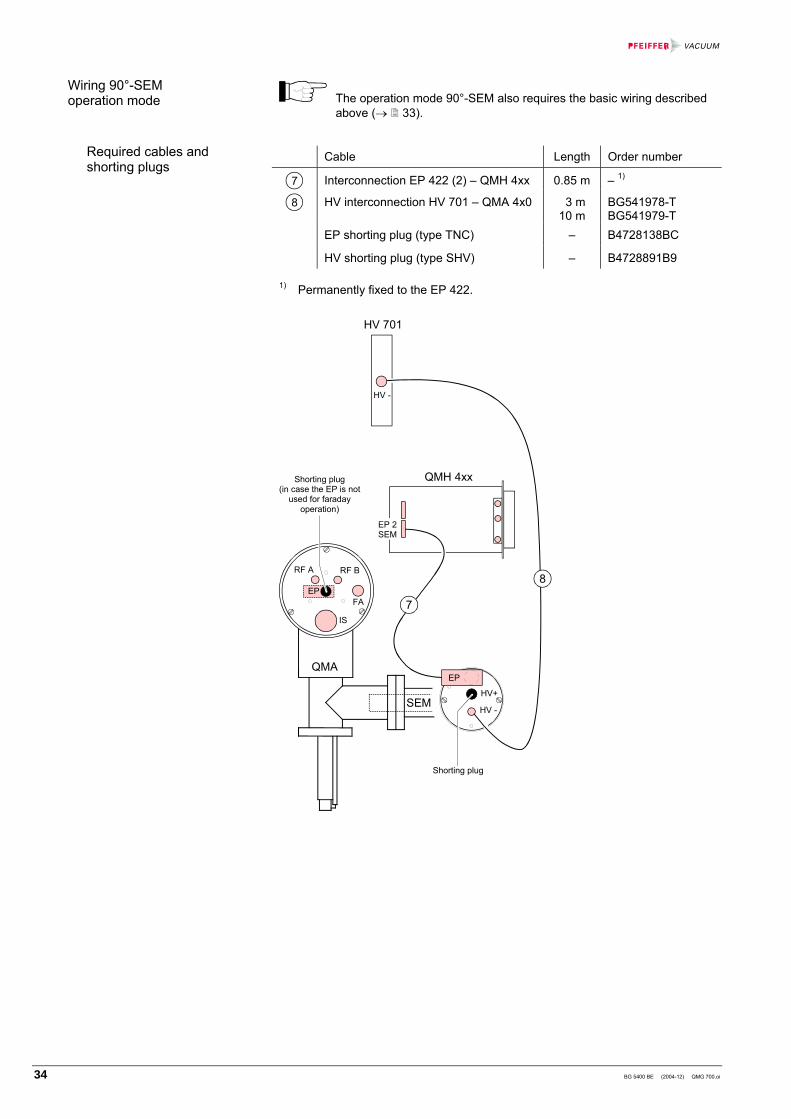
The operation mode 90°-SEM also requires the basic wiring described above (→ 33).
Cable Length Order number
7 Interconnection EP 422 (2) – QMH 4xx 0.85 m – 1)
8 HV interconnection HV 701 – QMA 4x0 3 m 10 m
BG541978-T BG541979-T
EP shorting plug (type TNC) – B4728138BC
HV shorting plug (type SHV) – B4728891B9
1) Permanently fixed to the EP 422.
Shorting plug
SEM
RF A RF B
FA
IS
EP
QMH 4xx
EP 2SEM
HV 701
HV -
QMAEP
HV+
HV -
7
8
Shorting plug(in case the EP is not
used for faradayoperation)
Wiring 90°-SEM operation mode
Required cables and shorting plugs

BG 5400 BE (2004-12) QMG 700.oi 35
The operation mode CP also requires the basic wiring described above (→ 33).
Cable Length Order number
9 HV interconnection HV 701 – CP 400 10 m BG448199-T
10 Interconnection QC 700 – CP 400 10 m BG541979-T
HV shorting plug (type SHV) – B4728891B9
RF A RF B
FA
IS
EP
QC 700
CP
HV 701
HV -
QMA CP 400
Shorting plug
HV+ QCHV-
9 10
Wiring CP operation mode (Ion counter)
Required cables and shorting plug

36 BG 5400 BE (2004-12) QMG 700.oi
Since the QMS 700 does not have a local control panel, it is operated via a PC interface or as a device in a network. There are various ways to interconnect a QMS 700 (QC 700) and a PC:
• For a direct link between a QC 700 and a PC the 8 core, crossed patch cable supplied with the QC is used (red, length 3 m, RJ45 connectors on both sides).
• For an interconnection via switch or in a network situation, the straight (1:1) patch cable is used (gray, length 3 m, RJ45 connectors on both sides, also supplied with the QC).
PC
Network, switch
Patch cable 1:1 (grey)
PC
Patch cable crossed (red)
In case of a USB link between the QC 700 and a PC, an regular USB cable with a type A connector on one end and a type B connector on the other end can be used.
PCUSB connectortyp B
USB connectortyp A
4.10 PC Connection
LAN interface
USB interface

BG 5400 BE (2004-12) QMG 700.oi 37
Options are factory installed if they have been ordered together with the system. They can also be installed in the field at any time.
Skilled personnel
Work on open equipment may only be performed by specialists. Switch off the unit before any manipulations on the equipment. Wait 60 s and detach all cables (power cable last). For commission perform these steps in re-verse order.
Cables are directly wired to the connection terminals on the I/O sub-modules inside the IO 700.
Detailed information can be found in the connection diagram delivered with the IO 700 (→ Appendix A).
Up to six cables (3 × Ø5 … 9 mm and 3 × Ø9 … 13 mm ) can be accommodated at the rear panel of the IO 700 module through six EMC-proof cable glands. For EMC reasons, shielded cables have to be used exclusively. The shielding mesh has to be sufficiently exposed in order to ensure reliable conductive clamping to chassis potential of the rear panel. A partly disassembled cable gland and the treatment of the cable end and the shielding mesh is shown in the figure below. Pay attention to the correct assem-bling order of the parts.
Shielding mesh
Cables and individual cores have to be strain relieved inside the IO 700 module.
4.11 IO 700 Wiring

38 BG 5400 BE (2004-12) QMG 700.oi
QMS 700 versions with the option "chassis expansion" installed will be delivered in the correct configuration and a supplementary documentation is added.
In a multi chassis system, slot assignment has to meet the following requirements:
• If the system comprises more than one chassis, all chassis have to be of the expansion type.
• The QC 700 must be installed in chassis No. 1, slot No.1 (left side of chassis, view on rear panels).
• In chassis No. 2, 3 and 4 slot No.1 must always contain an HV 701 or an IS 716 in order to satisfy the automatic configuration recogni-tion. The user can freely choose the rest of the chassis content and order of modules in the chassis (spaces between modules are per-mitted, but must be covered with blank panels).
• Power supplies of chassis No. 2, 3 and 4 must be switched on be-fore (or at least together with) the power supply of chassis No. 1, otherwise the internal module recognition routine is not working cor-rectly.
(Slot assignment and chassis interconnections → 12)
4.12 Operation of Two and More Chassis (optional)

BG 5400 BE (2004-12) QMG 700.oi 39
5 Operation
DANGER
Verify the correct installation of all system components and compliance with technical data (→ 11) before equipment is switched on.
Before the system is started up, check the following:
• Mains switch of QMS 700 is in OFF (O) position
• Correct installation of all system components and modules
• Correct condition of vacuum/process chamber
• Correct wiring of system components (→ 33)
• LAN- or USB link to PC (directly or via network) installed (→ 36)
• Interconnections between all QMS 700 chassis checked (only in case of op-tional expansion)
• Mains cable to QMS 700 installed
• PC ready for operation according to software instructions (→ [4]).
Consult operating instructions of all system components involved before you start up the system (→ [1] … [4]). In complete (factory configured) systems, settings and parameters have been optimally aligned. Do not change them unfounded.
After the conclusion of the checks listed above, the system can be switched on.
Switch mains switch on QMS 700 front panel to ON ( I ). The LED DC next to the mains switch lights up. The QMS 700 is ready for operation.
Switch the PC on and start the QUADERA® application software. A flickering yellow LED in the RJ45 LAN connector socket (QC 700 rear panel) indi-cates that data communication is in progress.
If this LED remains dark, a communication error has to be sus-pected. In this case, check the cables and components along the communication path. Also check the PC for correct configuration and installation (application software, firewall status etc.).
QUADERA® will then guide the user through the subsequent steps of the start up procedure (configuration, measurement range etc.).
5.1 Initial Start Up
Note before start up
Switching on
40 BG 5400 BE (2004-12) QMG 700.oi
6 Maintenance
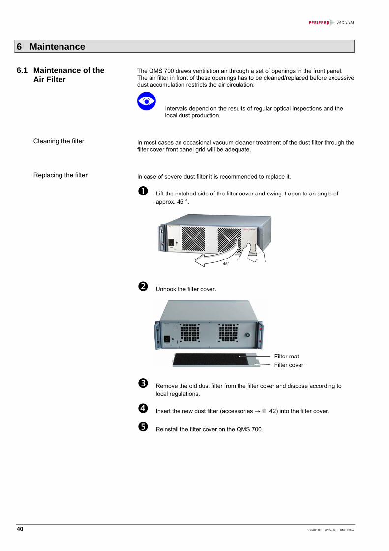
The QMS 700 draws ventilation air through a set of openings in the front panel. The air filter in front of these openings has to be cleaned/replaced before excessive dust accumulation restricts the air circulation.
Intervals depend on the results of regular optical inspections and the local dust production.
In most cases an occasional vacuum cleaner treatment of the dust filter through the filter cover front panel grid will be adequate.
In case of severe dust filter it is recommended to replace it.
Lift the notched side of the filter cover and swing it open to an angle of approx. 45 °.
45°
Unhook the filter cover.
Filter mat Filter cover
Remove the old dust filter from the filter cover and dispose according to local regulations.
Insert the new dust filter (accessories → 42) into the filter cover.
Reinstall the filter cover on the QMS 700.
6.1 Maintenance of the Air Filter
Cleaning the filter
Replacing the filter

BG 5400 BE (2004-12) QMG 700.oi 41
7 Repair
Skilled personnel
Work on an open unit may only be performed by skilled personnel. The relevant safety instructions given in the corresponding chapters must be conscientiously followed. Protection against electrostatic discharges (ESD) is absolutely essential, other-wise the Pfeiffer Vacuum warranty becomes null and void.
A defective mains fuse will cause the DC LED to stay dark even if mains voltage is applied and the mains switch is in ON position ( I ).
Usually a defective mains fuse indicates a serious problem in the unit or in the system. If after replacement the fuse blows again, it is strongly recommended to contact a Pfeiffer Vacuum service office.
View on SC 700 rear panel
SC 700
Mains fuse holder(with fuse carrier)
Switch QMS 700 off and remove its mains cable.
Open the fuse carrier of the mains fuse holder.
Replace defective fuse (6.3 AT HBC, 5×20 mm) and push the fuse carrier back into the mains fuse holder.
Make sure the mains switch Power is in position OFF (O).
Reconnect the mains cable.
Switch on the system.
General
7.1 Replacing the Mains Fuse
Replacing the fuse

42 BG 5400 BE (2004-12) QMG 700.oi
8 Accessories
When ordering, always indicate: • all information on the product name plate • description and ordering number according to list Ordering number Replacement dust filter 451-067 Blank panel 4U (20 mm) 46-0022 Blank panel 8U (40.3 mm) 46-0023 Blank panel 28U (141.9 m) 46-0024 Screws for blank panels 30-0017 Patch cable RJ45 1:1 grey 3 m 45-0006 Patch cable RJ45 crossed red 3 m 45-0007
9 Storage
Caution
Caution: electronic component Inappropriate storage (static electricity, humidity etc.) can damage electronic components. Store product in antistatic container. Observe the corresponding speci-fications in the Technical Data (→ 11).
10 Returning the Product
WARNING
Caution: forwarding contaminated products Contaminated products (e.g. radioactive, toxic, caustic or biological hazard) can be detrimental to health and environment. Products returned to Pfeiffer Vacuum should preferably be free of harmful substances. Adhere to the forwarding regulations of all in-volved countries and forwarding companies and enclose a duly com-pleted declaration of contamination (→ 46).
Products that are not clearly declared as "free of harmful substances" are decon-taminated at the expense of the customer. Products not accompanied by a duly completed declaration of contamination are returned to the sender at his own expense.

BG 5400 BE (2004-12) QMG 700.oi 43
11 Disposal
DANGER
Caution: contaminated parts Contaminated parts can be detrimental to health and environment. Before beginning to work, find out whether any parts are contami-nated. Adhere to the relevant regulations and take the necessary pre-cautions when handling contaminated parts.
N
WARNING
Caution: substances detrimental to the environment Products or parts thereof (mechanical and electric components, oper-ating fluids etc.) can be detrimental to the environment. Dispose of such substances in accordance with the relevant local regulations.
After disassembling the product, separate its components according to the follow-ing criteria:
Contaminated components (radioactive, toxic, caustic or biological hazard etc.) must be decontaminated in accordance with the relevant national regulations, separated according to their materials, and disposed of.
Such components must be separated according to their materials and recycled.
Separating the components
Contaminated components
Other components

44 BG 5400 BE (2004-12) QMG 700.oi
Appendix
Note sub-module specifications when wiring the I/O modules (→ 22).
+24
V
0V
CA
Nop
enC
OU
PLER
750-
337
24 V 0 V
AO
1A
NA
LOG
OU
T 4
CH
750-
559
AO
2
12
56
34
78
AO 1
AO 2
AO 3
AO 4
GN
D
AI 1
AN
ALO
G IN
4 C
H75
0-45
9
AI 2
12
56
34
78
AI 1
AI 2
AI 3
AI 4
END
MO
DU
LE75
0-60
0
0VG
ND
DO
1D
IGIT
AL
OU
T 8
BIT
750-
530
DO 1DO 2DO 3DO 4DO 5DO 6DO 7DO 8
DO
2D
O 3
DO
4
15
26
37
48
DI 1
DIG
ITA
L IN
8 B
IT75
0-43
0
DI 1DI 2DI 3DI 4DI 5DI 6DI 7DI 8
DI 2D
I 3DI 4
15
26
37
48
750
SYST
EMBU
S
max
0.5
Aty
p 2.
8 m
A
ISO
LATI
ON
ISO
LATI
ON
ISO
LATI
ON
ISO
LATI
ON
EXT
0V
EXT
+24
V
R_L
OAD
>5 K
+ -V IN
R_I
N 1
00 K
32 B
IT D
IGIT
AL O
UT
24 V
SO
UR
CE
32 B
IT D
IGIT
AL IN
24 V
8 C
H A
NA
LOG
OU
T0
... +
10 V
, 12
BIT
RE
SOLU
TIO
NS
ING
LE E
ND
ED
8 C
H A
NA
LOG
IN0
... +
10 V
, 12
BIT
RE
SOLU
TIO
NS
ING
LE E
ND
ED
CA
N G
ND
CA
N_L
(SH
IELD
)
CA
N_H
+24
V
EXT
ER
NA
L 24
VP
OW
ER
SU
PPLY
0 V
+24
V
max
10
A
blue
0.5
mm
2
red
0.5
mm
2
5a6c 5c 6a 1a 1c 16a
16c
yello
w 0
.25
mm
2
gree
n 0.
25 m
m2
blac
k 0.
25 m
m2
ISO
LATI
ON
-+
+-
CH
ASSI
SC
HAS
SIS
CH
ASSI
SC
HAS
SIS
10 n
F
CO
NNE
CTIO
N B
OAR
D
CO
NNE
CTIO
N B
OAR
D
5a6c 5c 6a 1a 1c 16a
16c
X1
FAC
TOR
Y W
IRIN
G
US
ER W
IRIN
G
TW
IST
ED
TW
IST
ED
EXT
+24V
EXT
0 V
X3X4
X2
Inte
rnal
QM
S 7
00 B
US
10 n
F10
nF
10 n
F
I/O M
odul
e IO
700
A: Connection Diagram IO 700

BG 5400 BE (2004-12) QMG 700.oi 45
[1] www. pfeiffer-vacuum.net Operating instructions RF Generator QMH 400 / 410 BG 805 982 BE Pfeiffer Vacuum GmbH, D-35614 Asslar, Deutschland
[2] www.pfeiffer-vacuum.net Operating instructions Analyzer QMA 400 / 410 / 430 BK 805 983 BE Pfeiffer Vacuum GmbH, D-35614 Asslar, Deutschland
[3] www.pfeiffer-vacuum.net Operating instructions Ion Counter Preamplifier CP 400 BG 805 812 BE Pfeiffer Vacuum GmbH, D-35614 Asslar, Deutschland
[4] www.pfeiffer-vacuum.net Software documentation QUADERA® Pfeiffer Vacuum GmbH, D–35614 Asslar, Deutschland
B: Literature

46 BG 5400 BE (2004-12) QMG 700.oi
Declaration of Contamination The service, repair, and/or disposal of vacuum equipment and components will only be carried out if a correctly completed declaration has been submitted. Non-completion will result in delay.This declaration may only be completed (in block letters) and signed by authorized and qualified staff.
Description of product Type Part number Serial number
Reason for return
Legally binding declaration: We hereby declare that the information on this form is complete and accurate and that we will assume any further costs that may arise. The contaminated product will be dispatched in accordance with the applicable regulations.
Organization/company Address Post code, place Phone Fax Email Name
Date and legally binding signature Company stamp
Copies:Original for addresee - 1 copy for accompanying documents - 1 copy for file of sender
Operating fluid(s) used (Must be drained before shipping.)
Harmful substances, gases and/or by-productsPlease list all substances, gases, and by-products which the product may have come into contact with:Trade/product name Chemical name
(or symbol)Precautions associatedwith substance
Action if human contact
The product is free of any sub-stances which are damaging tohealth. yes
Used in copper processno yes Seal product in plastic bag and
mark it with a corresponding label.
This form can be downloaded from our website.
2) Products thus contami- nated will not be ac- cepted without written evidence of decontami- nation.
1) or not containing any amount of hazardous residues that exceed the permissible ex- posure limits
Process related contamination of product: toxic no 1) yes caustic no 1) yes biological hazard no yes 2) explosive no yes 2) radioactive no yes 2) other harmful substances no 1) yes

BG 5400 BE (2004-12) QMG 700.oi 47
Declaration of Conformity
We, Pfeiffer Vacuum hereby declare that the equipment mentioned below complies with the provisions of the Directive relating to electrical equipment designed for use within certain voltage limits 73/23/EEC and the Directive relating to electromagnetic compatibility 89/336/EEC.
HiQuad Quadrupole Mass Spectrometry System
QMG 700
Harmonized and international/national standards and specifications: • EN 61010-1:2001 (Safety requirements for electrical equipment for
measurement, control and laboratory use) • EN 61326-1:1997 (Electrical equipment for measurement control and
laboratory use – EMC requirements) • EN 61326:1997/A1:1998 (Electrical equipment for measurement control and
laboratory use – EMC requirements)
Pfeiffer Vacuum GmbH, Asslar
23 December 2004
Wolfgang Dondorf Managing Director
Product
Standards
Signature

Berliner Strasse 43 D–35614 Asslar Deutschland Tel +49 (0) 6441 802-0 Fax +49 (0) 6441 802-202
Original: German BG 5400 BD (2004-12) [email protected]
bg5400be www.pfeiffer-vacuum.net