Hilti HIT-ICE mortar with HIT-V / HAS rod · PDF fileHilti HIT-ICE mortar with HIT-V / HAS rod...
34
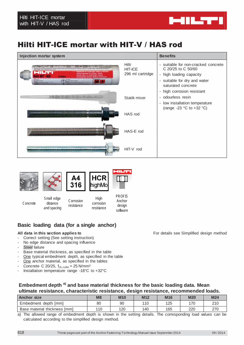
Hilti HIT-ICE mortar with HIT-V / HAS rod These pages are part of the Anchor Fastening Technology Manual issue September 2014 09 / 2014 818 Hilti HIT-ICE mortar with HIT-V / HAS rod Injection mortar system Benefits Hilti HIT -ICE 296 ml cartridge - suitable for non-cracked concrete C 20/25 to C 50/60 - high loading capacity - suitable for dry and water saturated concrete - high corrosion resistant - odourless resin - low installation temperature (range -23 °C to +32 °C) Statik mixer HAS rod HAS-E rod HIT -V rod Concrete Small edge distance and spacing Corrosion resistance High corrosion resistance PROFIS Anchor design software Basic loading data (for a single anchor) All data in this section applies to For details see Simplified design method - Correct setting (See setting instruction) - No edge distance and spacing influence - Steel failure - Base material thickness, as specified in the table - One typical embedment depth, as specified in the table - One anchor material, as specified in the tables - Concrete C 20/25, f ck,cube = 25 N/mm² - Installation temperature range -18°C to +32°C Embedment depth a) and base material thickness for the basic loading data. Mean ultimate resistance, characteristic resistance, design resistance, recommended loads. Anchor size M8 M10 M12 M16 M20 M24 Embedment depth [mm] 80 90 110 125 170 210 Base material thickness [mm] 110 120 140 165 220 270 a) The allowed range of embedment depth is shown in the setting details. The corresponding load values can be calculated according to the simplified design method.
Transcript of Hilti HIT-ICE mortar with HIT-V / HAS rod · PDF fileHilti HIT-ICE mortar with HIT-V / HAS rod...
Hilti HIT-ICE mortar with HIT-V / HAS rod
These pages are part of the Anchor Fastening Technology Manual issue September 2014 09 / 2014 818
Hilti HIT-ICE mortar with HIT-V / HAS rod Injection mortar system Benefits
Hilti HIT-ICE 296 ml cartridge
- suitable for non-cracked concrete C 20/25 to C 50/60
- high loading capacity - suitable for dry and water
saturated concrete - high corrosion resistant - odourless resin - low installation temperature
(range -23 °C to +32 °C)
Statik mixer
HAS rod
HAS-E rod
HIT-V rod
Concrete Small edge
distance and spacing
Corrosion resistance
High corrosion resistance
PROFIS Anchor design
software
Basic loading data (for a single anchor)All data in this section applies to For details see Simplified design method - Correct setting (See setting instruction) - No edge distance and spacing influence - Steel failure - Base material thickness, as specified in the table - One typical embedment depth, as specified in the table - One anchor material, as specified in the tables - Concrete C 20/25, fck,cube = 25 N/mm² - Installation temperature range -18°C to +32°C Embedment depth a) and base material thickness for the basic loading data. Mean ultimate resistance, characteristic resistance, design resistance, recommended loads. Anchor size M8 M10 M12 M16 M20 M24 Embedment depth [mm] 80 90 110 125 170 210 Base material thickness [mm] 110 120 140 165 220 270
a) The allowed range of embedment depth is shown in the setting details. The corresponding load values can be calculated according to the simplified design method.
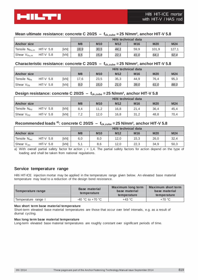
Hilti HIT-ICE mortar
with HIT-V / HAS rod
09 / 2014 These pages are part of the Anchor Fastening Technology Manual issue September 2014
819
Mean ultimate resistance: concrete C 20/25 – fck,cube = 25 N/mm², anchor HIT-V 5.8 Hilti technical data Anchor size M8 M10 M12 M16 M20 M24 Tensile NRu,m HIT-V 5.8 [kN] 18,9 30,5 44,1 59,9 101,9 127,1
Shear VRu,m HIT-V 5.8 [kN] 9,5 15,8 22,1 41,0 64,1 92,4 Characteristic resistance: concrete C 20/25 – fck,cube = 25 N/mm², anchor HIT-V 5.8 Hilti technical data Anchor size M8 M10 M12 M16 M20 M24 Tensile NRk HIT-V 5.8 [kN] 17,6 23,5 35,3 44,9 76,4 95,3
Shear VRk HIT-V 5.8 [kN] 9,0 15,0 21,0 39,0 61,0 88,0 Design resistance: concrete C 20/25 – fck,cube = 25 N/mm², anchor HIT-V 5.8 Hilti technical data Anchor size M8 M10 M12 M16 M20 M24 Tensile NRd HIT-V 5.8 [kN] 8,4 11,2 16,8 21,4 36,4 45,4
Shear VRd HIT-V 5.8 [kN] 7,2 12,0 16,8 31,2 48,8 70,4 Recommended loads a): concrete C 20/25 – fck,cube = 25 N/mm², anchor HIT-V 5.8 Hilti technical data Anchor size M8 M10 M12 M16 M20 M24 Tensile Nrec HIT-V 5.8 [kN] 6,0 8,0 12,0 15,3 26,0 32,4
Shear Vrec HIT-V 5.8 [kN] 5,1 8,6 12,0 22,3 34,9 50,3 a) With overall partial safety factor for action = 1,4. The partial safety factors for action depend on the type of
loading and shall be taken from national regulations. Service temperature range Hilti HIT-ICE injection mortar may be applied in the temperature range given below. An elevated base material temperature may lead to a reduction of the design bond resistance.
Temperature range Base material temperature
Maximum long term base material temperature
Maximum short term base material temperature
Temperature range I -40 °C to +70 °C +43 °C +70 °C
Max short term base material temperature Short-term elevated base material temperatures are those that occur over brief intervals, e.g. as a result of diurnal cycling.
Max long term base material temperature Long-term elevated base material temperatures are roughly constant over significant periods of time.
Hilti HIT-ICE mortar with HIT-V / HAS rod
These pages are part of the Anchor Fastening Technology Manual issue September 2014 09 / 2014
820
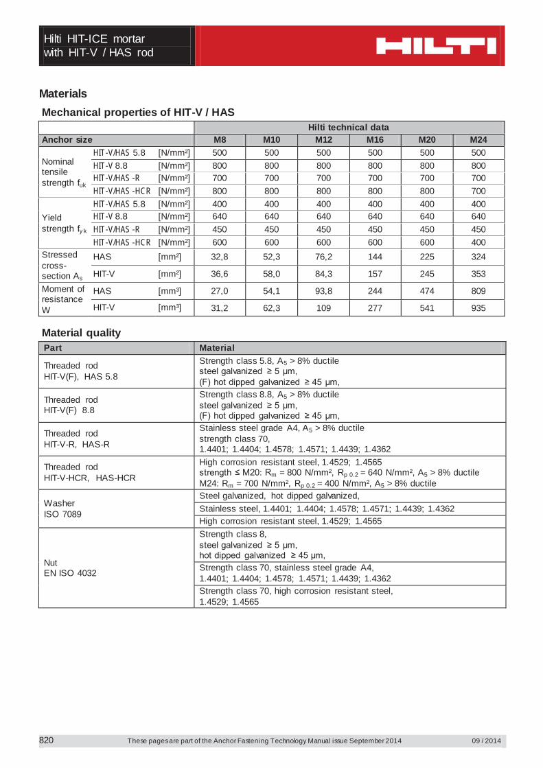
Materials Mechanical properties of HIT-V / HAS Hilti technical data Anchor size M8 M10 M12 M16 M20 M24
Nominal tensile strength fuk
HIT-V/HAS 5.8 [N/mm²] 500 500 500 500 500 500 HIT-V 8.8 [N/mm²] 800 800 800 800 800 800 HIT-V/HAS -R [N/mm²] 700 700 700 700 700 700 HIT-V/HAS -HCR [N/mm²] 800 800 800 800 800 700
Yield strength fy k
HIT-V/HAS 5.8 [N/mm²] 400 400 400 400 400 400 HIT-V 8.8 [N/mm²] 640 640 640 640 640 640 HIT-V/HAS -R [N/mm²] 450 450 450 450 450 450 HIT-V/HAS -HCR [N/mm²] 600 600 600 600 600 400
Stressed cross-section As
HAS [mm²] 32,8 52,3 76,2 144 225 324
HIT-V [mm²] 36,6 58,0 84,3 157 245 353
Moment of resistance W
HAS [mm³] 27,0 54,1 93,8 244 474 809
HIT-V [mm³] 31,2 62,3 109 277 541 935 Material quality Part Material
Threaded rod HIT-V(F), HAS 5.8
Strength class 5.8, A5 > 8% ductile steel galvanized ≥ 5 μm, (F) hot dipped galvanized ≥ 45 μm,
Threaded rod HIT-V(F) 8.8
Strength class 8.8, A5 > 8% ductile steel galvanized ≥ 5 μm, (F) hot dipped galvanized ≥ 45 μm,
Threaded rod HIT-V-R, HAS-R
Stainless steel grade A4, A5 > 8% ductile strength class 70, 1.4401; 1.4404; 1.4578; 1.4571; 1.4439; 1.4362
Threaded rod HIT-V-HCR, HAS-HCR
High corrosion resistant steel, 1.4529; 1.4565 strength ≤ M20: Rm = 800 N/mm², Rp 0.2 = 640 N/mm², A5 > 8% ductile M24: Rm = 700 N/mm², Rp 0.2 = 400 N/mm², A5 > 8% ductile
Washer ISO 7089
Steel galvanized, hot dipped galvanized, Stainless steel, 1.4401; 1.4404; 1.4578; 1.4571; 1.4439; 1.4362 High corrosion resistant steel, 1.4529; 1.4565
Nut EN ISO 4032
Strength class 8, steel galvanized ≥ 5 μm, hot dipped galvanized ≥ 45 μm, Strength class 70, stainless steel grade A4, 1.4401; 1.4404; 1.4578; 1.4571; 1.4439; 1.4362 Strength class 70, high corrosion resistant steel, 1.4529; 1.4565
Hilti HIT-ICE mortar
with HIT-V / HAS rod
09 / 2014 These pages are part of the Anchor Fastening Technology Manual issue September 2014
821
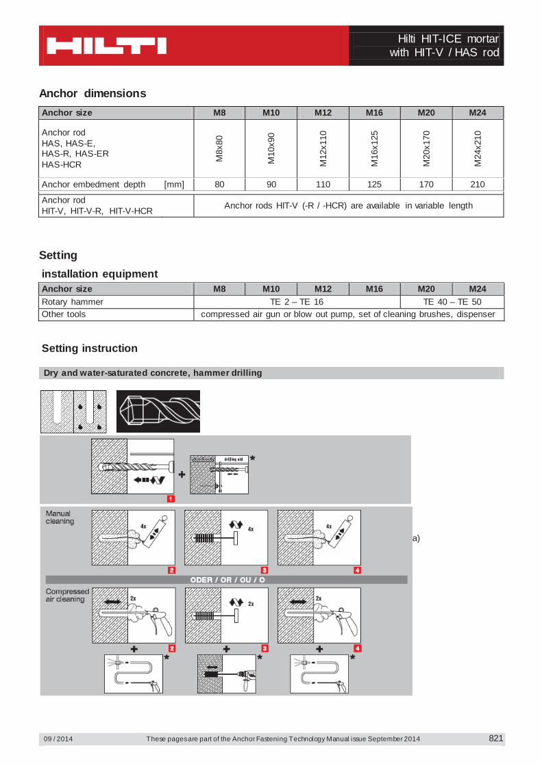
Anchor dimensions Anchor size M8 M10 M12 M16 M20 M24
Anchor rod HAS, HAS-E, HAS-R, HAS-ER HAS-HCR
M8x
80
M10
x90
M12
x110
M16
x125
M20
x170
M24
x210
Anchor embedment depth [mm] 80 90 110 125 170 210
Anchor rod HIT-V, HIT-V-R, HIT-V-HCR Anchor rods HIT-V (-R / -HCR) are available in variable length
Setting installation equipment Anchor size M8 M10 M12 M16 M20 M24 Rotary hammer TE 2 – TE 16 TE 40 – TE 50 Other tools compressed air gun or blow out pump, set of cleaning brushes, dispenser
Setting instruction
Dry and water-saturated concrete, hammer drilling
a)
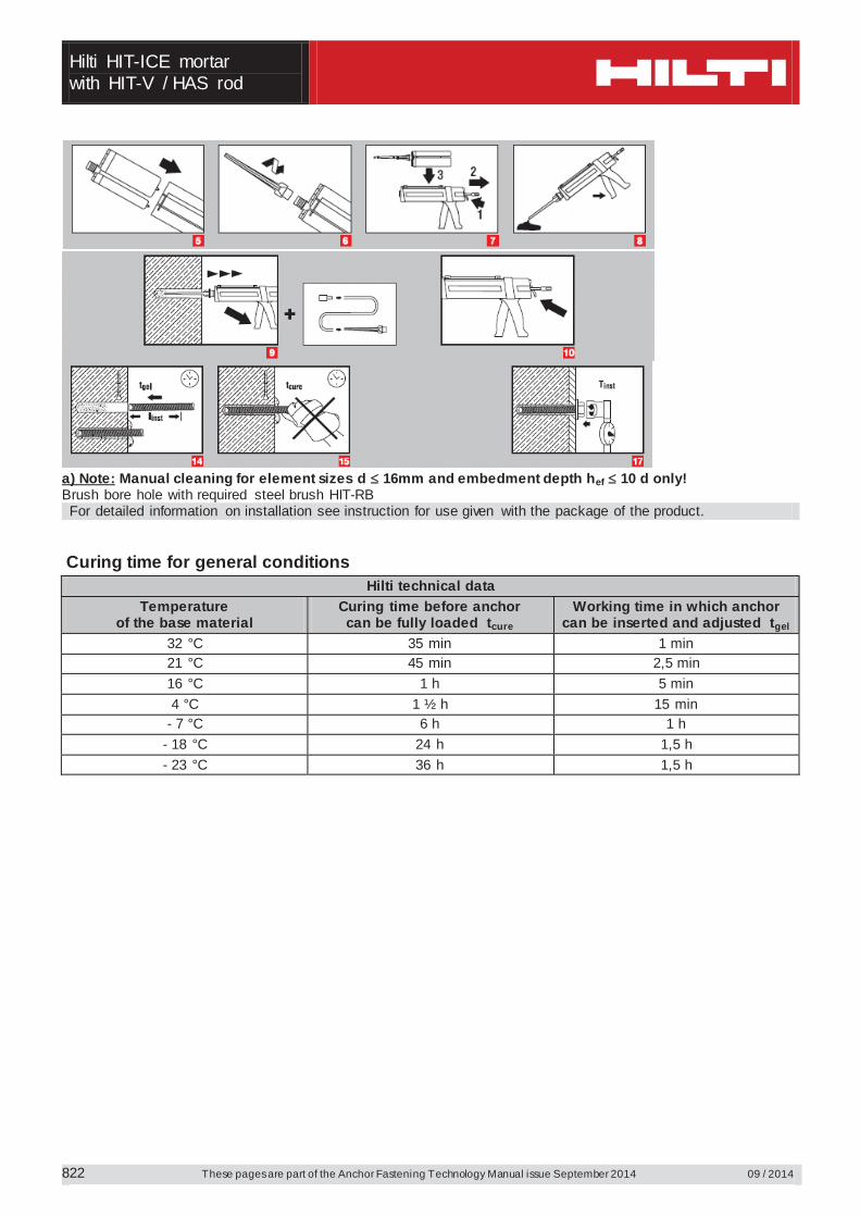
Hilti HIT-ICE mortar with HIT-V / HAS rod
These pages are part of the Anchor Fastening Technology Manual issue September 2014 09 / 2014
822
a) Note: Manual cleaning for element sizes d 16mm and embedment depth hef 10 d only! Brush bore hole with required steel brush HIT-RB For detailed information on installation see instruction for use given with the package of the product.
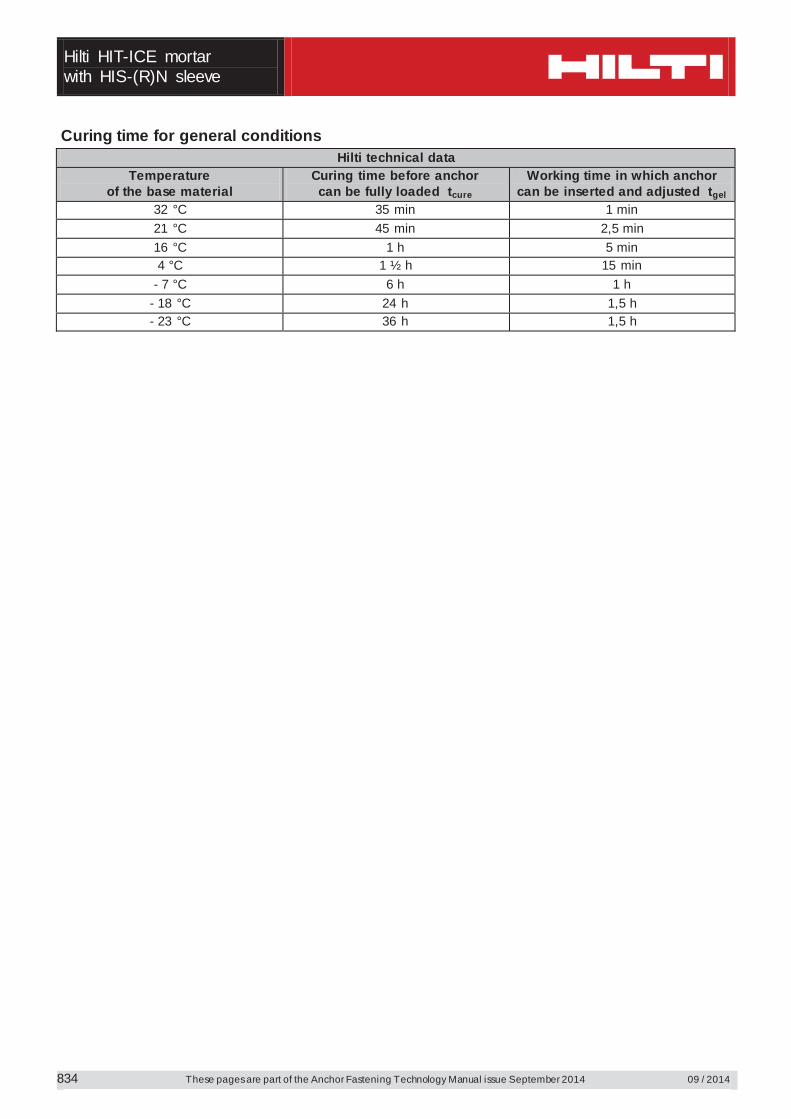
Curing time for general conditions
Hilti technical data Temperature
of the base material Curing time before anchor can be fully loaded tcure
Working time in which anchor can be inserted and adjusted tgel
32 °C 35 min 1 min 21 °C 45 min 2,5 min 16 °C 1 h 5 min 4 °C 1 ½ h 15 min
- 7 °C 6 h 1 h - 18 °C 24 h 1,5 h - 23 °C 36 h 1,5 h
Hilti HIT-ICE mortar
with HIT-V / HAS rod
09 / 2014 These pages are part of the Anchor Fastening Technology Manual issue September 2014
823
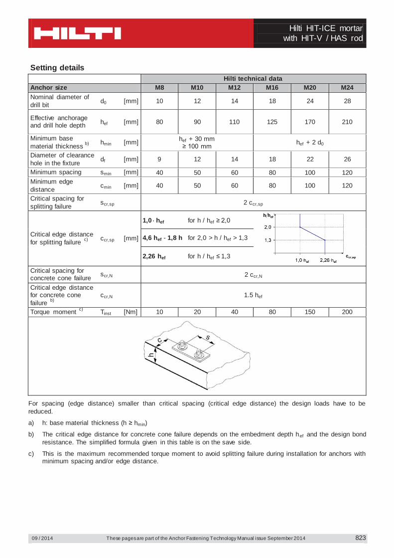
Setting details Hilti technical data Anchor size M8 M10 M12 M16 M20 M24 Nominal diameter of drill bit d0 [mm] 10 12 14 18 24 28
Effective anchorage and drill hole depth hef [mm] 80 90 110 125 170 210
Minimum base material thickness b) hmin [mm] hef + 30 mm
≥ 100 mm hef + 2 d0
Diameter of clearance hole in the fixture df [mm] 9 12 14 18 22 26
Minimum spacing smin [mm] 40 50 60 80 100 120 Minimum edge distance cmin [mm] 40 50 60 80 100 120
Critical spacing for splitting failure scr,sp 2 ccr,sp
Critical edge distance for splitting failure c) ccr,sp [mm]
1,0 hef for h / hef ≥ 2,0
4,6 hef - 1,8 h for 2,0 > h / hef > 1,3
2,26 hef for h / hef ≤ 1,3
Critical spacing for concrete cone failure scr,N 2 ccr,N
Critical edge distance for concrete cone failure b)
ccr,N 1.5 hef
Torque moment c) Tinst [Nm] 10 20 40 80 150 200
For spacing (edge distance) smaller than critical spacing (critical edge distance) the design loads have to be reduced.
a) h: base material thickness (h ≥ hmin)
b) The critical edge distance for concrete cone failure depends on the embedment depth hef and the design bond resistance. The simplified formula given in this table is on the save side.
c) This is the maximum recommended torque moment to avoid splitting failure during installation for anchors with minimum spacing and/or edge distance.
Hilti HIT-ICE mortar with HIT-V / HAS rod
These pages are part of the Anchor Fastening Technology Manual issue September 2014 09 / 2014
824
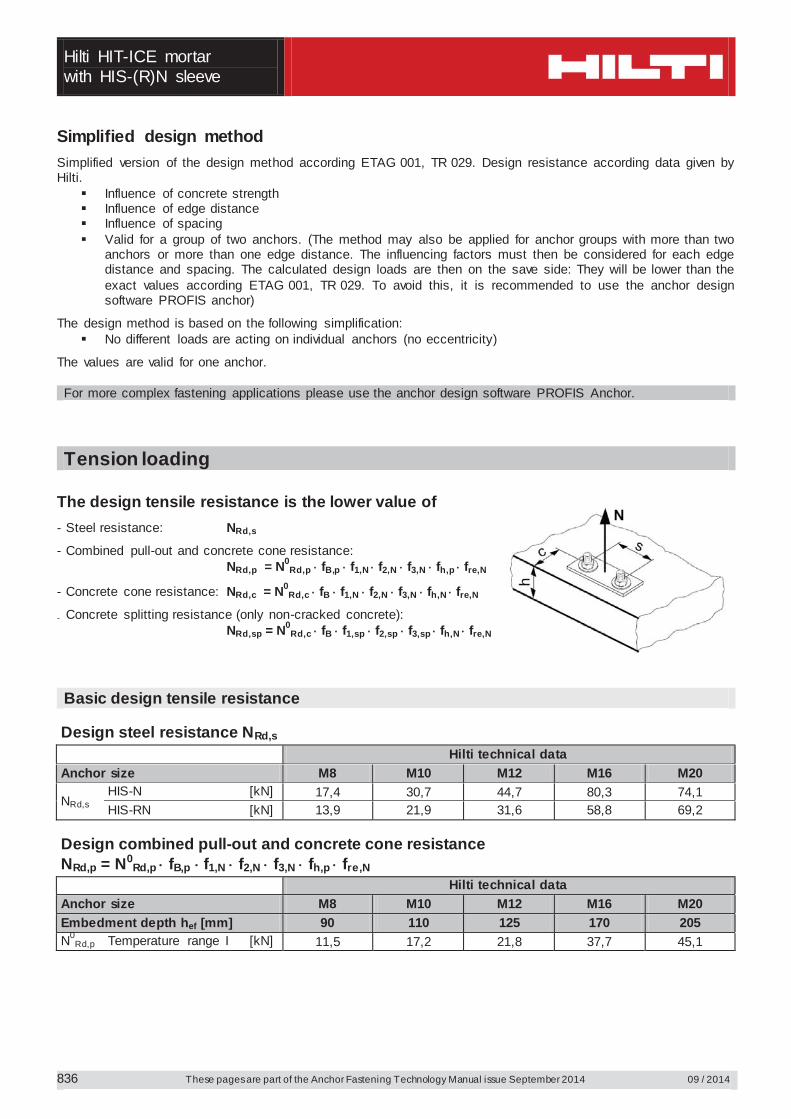
Simplified design method Simplified version of the design method according ETAG 001, TR 029. Design resistance according data given by Hilti.
Influence of concrete strength Influence of edge distance Influence of spacing Valid for a group of two anchors. (The method may also be applied for anchor groups with more than two
anchors or more than one edge distance. The influencing factors must then be considered for each edge distance and spacing. The calculated design loads are then on the save side: They will be lower than the exact values according ETAG 001, TR 029. To avoid this, it is recommended to use the anchor design software PROFIS anchor)
The design method is based on the following simplification: No different loads are acting on individual anchors (no eccentricity)
The values are valid for one anchor. For more complex fastening applications please use the anchor design software PROFIS Anchor.
Tension loading
The design tensile resistance is the lower value of - Steel resistance: NRd,s
- Combined pull-out and concrete cone resistance: NRd,p = N0
Rd,p fB,p f1,N f2,N f3,N fh,p fre,N
- Concrete cone resistance: NRd,c = N0Rd,c fB f1,N f2,N f3,N fh,N fre,N
- Concrete splitting resistance (only non-cracked concrete): NRd,sp = N0
Rd,c fB f1,sp f2,sp f3,sp fh,N fre,N
Basic design tensile resistance
Design steel resistance NRd,s Hilti technical data Anchor size M8 M10 M12 M16 M20 M24
NRd,s
HAS 5.8 [kN] 11,1 17,6 25,4 48,1 74,8 106,8 HIT-V 5.8 [kN] 12,0 19,3 28,0 52,7 82,0 118,0 HIT-V 8.8 [kN] 19,3 30,7 44,7 84,0 130,7 188,0 HAS (-E)-R [kN] 12,4 19,8 28,6 54,1 84,1 120,2 HIT-V-R [kN] 13,9 21,9 31,6 58,8 92,0 132,1 HAS (-E)-HCR [kN] 17,7 28,2 40,6 76,9 119,6 106,8 HIT-V-HCR [kN] 19,3 30,7 44,7 84,0 130,7 117,6
Design combined pull-out and concrete cone resistance NRd,p = N0
Rd,p fB,p f1,N f2,N f3,N fh,p fre,N Hilti technical data Anchor size M8 M10 M12 M16 M20 M24 Typical embedment depth hef,typ [mm] 80 90 110 125 170 210
N0Rd,p Temperature range I [kN] 8,4 11,2 16,8 21,4 36,4 45,4
Hilti HIT-ICE mortar
with HIT-V / HAS rod
09 / 2014 These pages are part of the Anchor Fastening Technology Manual issue September 2014
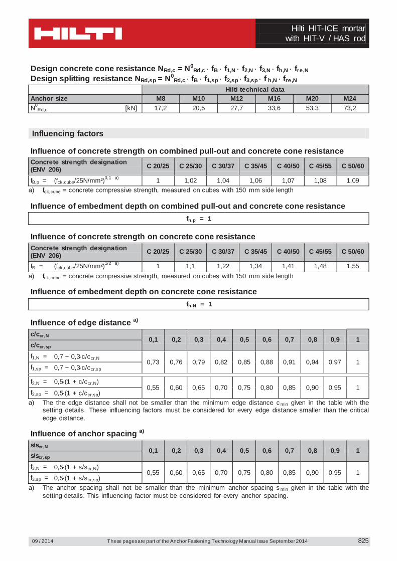
825
Design concrete cone resistance NRd,c = N0Rd,c fB f1,N f2,N f3,N fh,N fre,N
Design splitting resistance NRd,sp = N0Rd,c fB f1,sp f2,sp f3,sp f h,N fre,N
Hilti technical data Anchor size M8 M10 M12 M16 M20 M24 N0
Rd,c [kN] 17,2 20,5 27,7 33,6 53,3 73,2 Influencing factors
Influence of concrete strength on combined pull-out and concrete cone resistance Concrete strength designation (ENV 206) C 20/25 C 25/30 C 30/37 C 35/45 C 40/50 C 45/55 C 50/60
fB,p = (fck,cube/25N/mm²)0,1 a) 1 1,02 1,04 1,06 1,07 1,08 1,09 a) fck,cube = concrete compressive strength, measured on cubes with 150 mm side length Influence of embedment depth on combined pull-out and concrete cone resistance
fh,p = 1
Influence of concrete strength on concrete cone resistance
Concrete strength designation (ENV 206) C 20/25 C 25/30 C 30/37 C 35/45 C 40/50 C 45/55 C 50/60
fB = (fck,cube/25N/mm²)1/2 a) 1 1,1 1,22 1,34 1,41 1,48 1,55 a) fck,cube = concrete compressive strength, measured on cubes with 150 mm side length Influence of embedment depth on concrete cone resistance
fh,N = 1
Influence of edge distance a)
c/ccr,N 0,1 0,2 0,3 0,4 0,5 0,6 0,7 0,8 0,9 1
c/ccr,sp f1,N = 0,7 + 0,3 c/ccr,N
0,73 0,76 0,79 0,82 0,85 0,88 0,91 0,94 0,97 1 f1,sp = 0,7 + 0,3 c/ccr,sp
f2,N = 0,5 (1 + c/ccr,N)
0,55 0,60 0,65 0,70 0,75 0,80 0,85 0,90 0,95 1 f2,sp = 0,5 (1 + c/ccr,sp)
a) The the edge distance shall not be smaller than the minimum edge distance c min given in the table with the setting details. These influencing factors must be considered for every edge distance smaller than the critical edge distance.
Influence of anchor spacing a)
s/scr,N 0,1 0,2 0,3 0,4 0,5 0,6 0,7 0,8 0,9 1
s/scr,sp f3,N = 0,5 (1 + s/scr,N)
0,55 0,60 0,65 0,70 0,75 0,80 0,85 0,90 0,95 1 f3,sp = 0,5 (1 + s/scr,sp)
a) The anchor spacing shall not be smaller than the minimum anchor spacing s min given in the table with the setting details. This influencing factor must be considered for every anchor spacing.
Hilti HIT-ICE mortar with HIT-V / HAS rod
These pages are part of the Anchor Fastening Technology Manual issue September 2014 09 / 2014
826
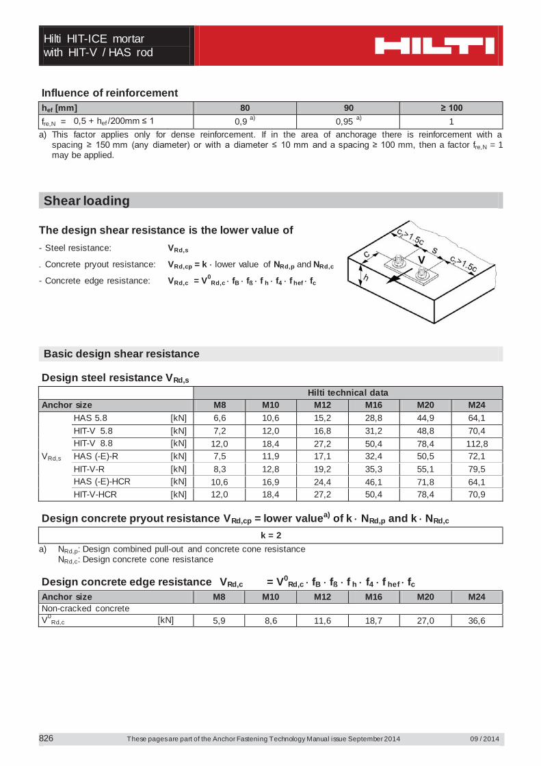
Influence of reinforcement hef [mm] 80 90 ≥ 100 fre,N = 0,5 + hef /200mm ≤ 1 0,9 a) 0,95 a) 1
a) This factor applies only for dense reinforcement. If in the area of anchorage there is reinforcement with a spacing ≥ 150 mm (any diameter) or with a diameter ≤ 10 mm and a spacing ≥ 100 mm, then a factor fre,N = 1 may be applied.
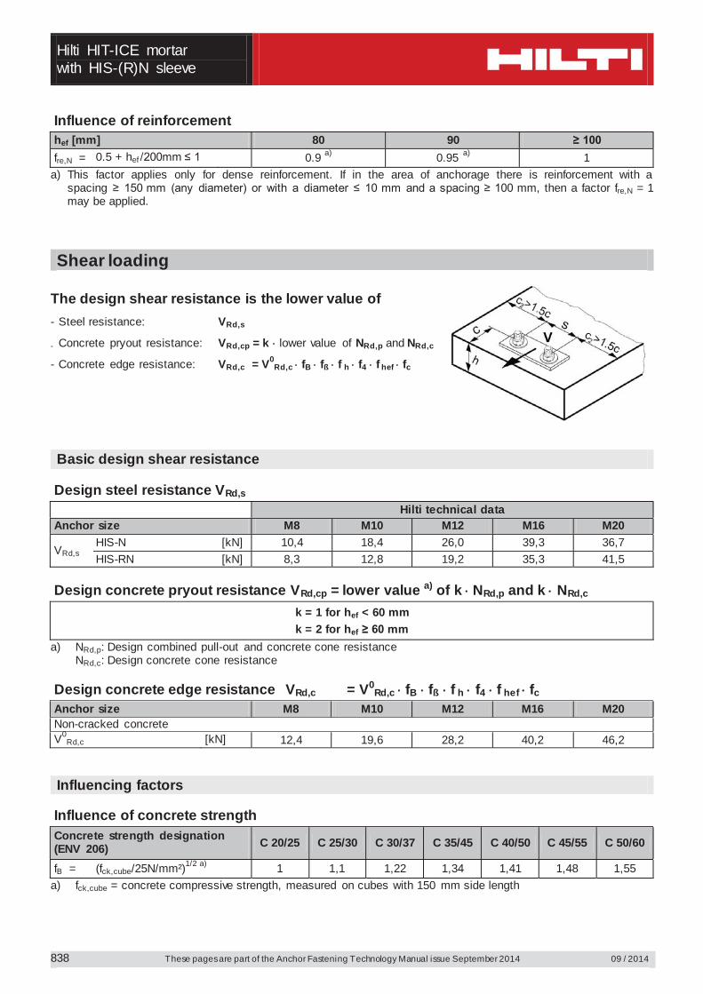
Shear loading
The design shear resistance is the lower value of - Steel resistance: VRd,s
- Concrete pryout resistance: VRd,cp = k lower value of NRd,p and NRd,c
- Concrete edge resistance: VRd,c = V0Rd,c fB fß f h f4 f hef fc
Basic design shear resistance
Design steel resistance VRd,s Hilti technical data Anchor size M8 M10 M12 M16 M20 M24
VRd,s
HAS 5.8 [kN] 6,6 10,6 15,2 28,8 44,9 64,1 HIT-V 5.8 [kN] 7,2 12,0 16,8 31,2 48,8 70,4 HIT-V 8.8 [kN] 12,0 18,4 27,2 50,4 78,4 112,8 HAS (-E)-R [kN] 7,5 11,9 17,1 32,4 50,5 72,1 HIT-V-R [kN] 8,3 12,8 19,2 35,3 55,1 79,5 HAS (-E)-HCR [kN] 10,6 16,9 24,4 46,1 71,8 64,1 HIT-V-HCR [kN] 12,0 18,4 27,2 50,4 78,4 70,9
Design concrete pryout resistance VRd,cp = lower valuea) of k NRd,p and k NRd,c
k = 2
a) NRd,p: Design combined pull-out and concrete cone resistance NRd,c: Design concrete cone resistance
Design concrete edge resistance VRd,c = V0
Rd,c fB fß f h f4 f hef fc Anchor size M8 M10 M12 M16 M20 M24 Non-cracked concrete V0
Rd,c [kN] 5,9 8,6 11,6 18,7 27,0 36,6
Hilti HIT-ICE mortar
with HIT-V / HAS rod
09 / 2014 These pages are part of the Anchor Fastening Technology Manual issue September 2014
827
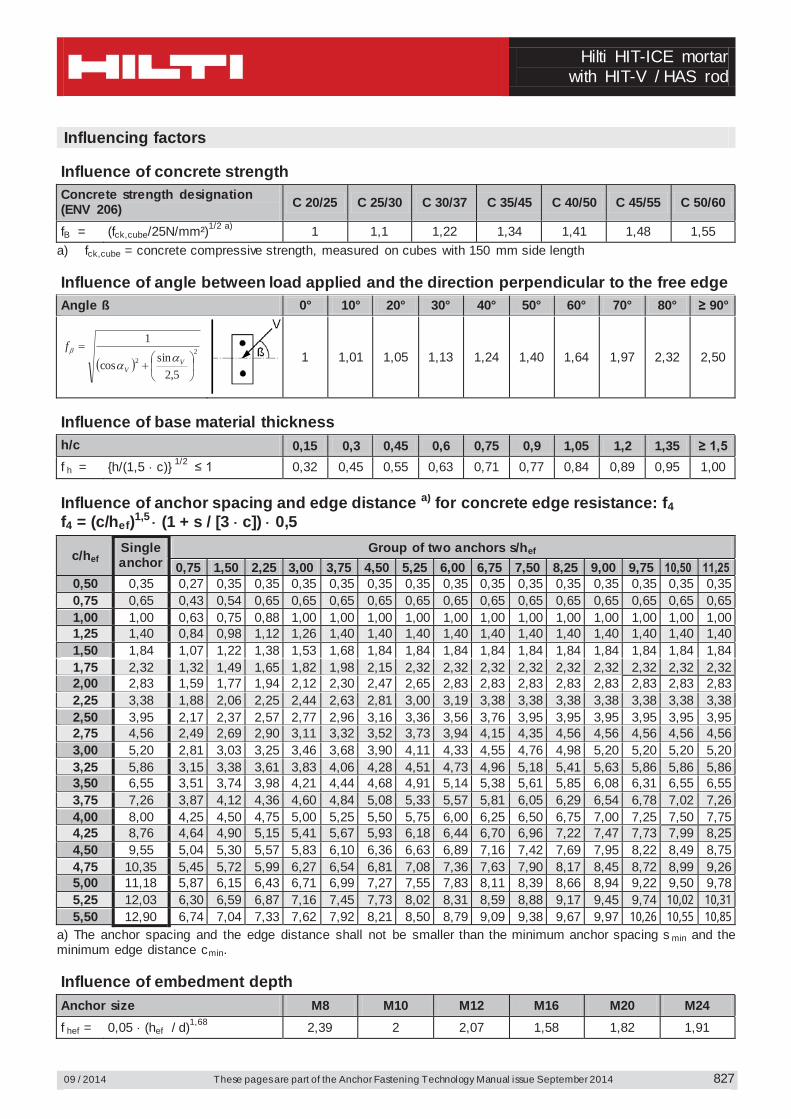
Influencing factors Influence of concrete strength
Concrete strength designation (ENV 206) C 20/25 C 25/30 C 30/37 C 35/45 C 40/50 C 45/55 C 50/60
fB = (fck,cube/25N/mm²)1/2 a) 1 1,1 1,22 1,34 1,41 1,48 1,55 a) fck,cube = concrete compressive strength, measured on cubes with 150 mm side length Influence of angle between load applied and the direction perpendicular to the free edge
Angle ß 0° 10° 20° 30° 40° 50° 60° 70° 80° ≥ 90°
22
5,2sincos
1
VV
f
1 1,01 1,05 1,13 1,24 1,40 1,64 1,97 2,32 2,50
Influence of base material thickness
h/c 0,15 0,3 0,45 0,6 0,75 0,9 1,05 1,2 1,35 ≥ 1,5 f h = {h/(1,5 c)} 1/2 ≤ 1 0,32 0,45 0,55 0,63 0,71 0,77 0,84 0,89 0,95 1,00
Influence of anchor spacing and edge distance a) for concrete edge resistance: f4 f4 = (c/hef)1,5 (1 + s / [3 c]) 0,5
c/hef Single anchor
Group of two anchors s/hef 0,75 1,50 2,25 3,00 3,75 4,50 5,25 6,00 6,75 7,50 8,25 9,00 9,75 10,50 11,25
0,50 0,35 0,27 0,35 0,35 0,35 0,35 0,35 0,35 0,35 0,35 0,35 0,35 0,35 0,35 0,35 0,35 0,75 0,65 0,43 0,54 0,65 0,65 0,65 0,65 0,65 0,65 0,65 0,65 0,65 0,65 0,65 0,65 0,65 1,00 1,00 0,63 0,75 0,88 1,00 1,00 1,00 1,00 1,00 1,00 1,00 1,00 1,00 1,00 1,00 1,00 1,25 1,40 0,84 0,98 1,12 1,26 1,40 1,40 1,40 1,40 1,40 1,40 1,40 1,40 1,40 1,40 1,40 1,50 1,84 1,07 1,22 1,38 1,53 1,68 1,84 1,84 1,84 1,84 1,84 1,84 1,84 1,84 1,84 1,84 1,75 2,32 1,32 1,49 1,65 1,82 1,98 2,15 2,32 2,32 2,32 2,32 2,32 2,32 2,32 2,32 2,32 2,00 2,83 1,59 1,77 1,94 2,12 2,30 2,47 2,65 2,83 2,83 2,83 2,83 2,83 2,83 2,83 2,83 2,25 3,38 1,88 2,06 2,25 2,44 2,63 2,81 3,00 3,19 3,38 3,38 3,38 3,38 3,38 3,38 3,38 2,50 3,95 2,17 2,37 2,57 2,77 2,96 3,16 3,36 3,56 3,76 3,95 3,95 3,95 3,95 3,95 3,95 2,75 4,56 2,49 2,69 2,90 3,11 3,32 3,52 3,73 3,94 4,15 4,35 4,56 4,56 4,56 4,56 4,56 3,00 5,20 2,81 3,03 3,25 3,46 3,68 3,90 4,11 4,33 4,55 4,76 4,98 5,20 5,20 5,20 5,20 3,25 5,86 3,15 3,38 3,61 3,83 4,06 4,28 4,51 4,73 4,96 5,18 5,41 5,63 5,86 5,86 5,86 3,50 6,55 3,51 3,74 3,98 4,21 4,44 4,68 4,91 5,14 5,38 5,61 5,85 6,08 6,31 6,55 6,55 3,75 7,26 3,87 4,12 4,36 4,60 4,84 5,08 5,33 5,57 5,81 6,05 6,29 6,54 6,78 7,02 7,26 4,00 8,00 4,25 4,50 4,75 5,00 5,25 5,50 5,75 6,00 6,25 6,50 6,75 7,00 7,25 7,50 7,75 4,25 8,76 4,64 4,90 5,15 5,41 5,67 5,93 6,18 6,44 6,70 6,96 7,22 7,47 7,73 7,99 8,25 4,50 9,55 5,04 5,30 5,57 5,83 6,10 6,36 6,63 6,89 7,16 7,42 7,69 7,95 8,22 8,49 8,75 4,75 10,35 5,45 5,72 5,99 6,27 6,54 6,81 7,08 7,36 7,63 7,90 8,17 8,45 8,72 8,99 9,26 5,00 11,18 5,87 6,15 6,43 6,71 6,99 7,27 7,55 7,83 8,11 8,39 8,66 8,94 9,22 9,50 9,78 5,25 12,03 6,30 6,59 6,87 7,16 7,45 7,73 8,02 8,31 8,59 8,88 9,17 9,45 9,74 10,02 10,31 5,50 12,90 6,74 7,04 7,33 7,62 7,92 8,21 8,50 8,79 9,09 9,38 9,67 9,97 10,26 10,55 10,85
a) The anchor spacing and the edge distance shall not be smaller than the minimum anchor spacing s min and the minimum edge distance cmin. Influence of embedment depth
Anchor size M8 M10 M12 M16 M20 M24 f hef = 0,05 (hef / d)1,68 2,39 2 2,07 1,58 1,82 1,91
Hilti HIT-ICE mortar with HIT-V / HAS rod
These pages are part of the Anchor Fastening Technology Manual issue September 2014 09 / 2014
828
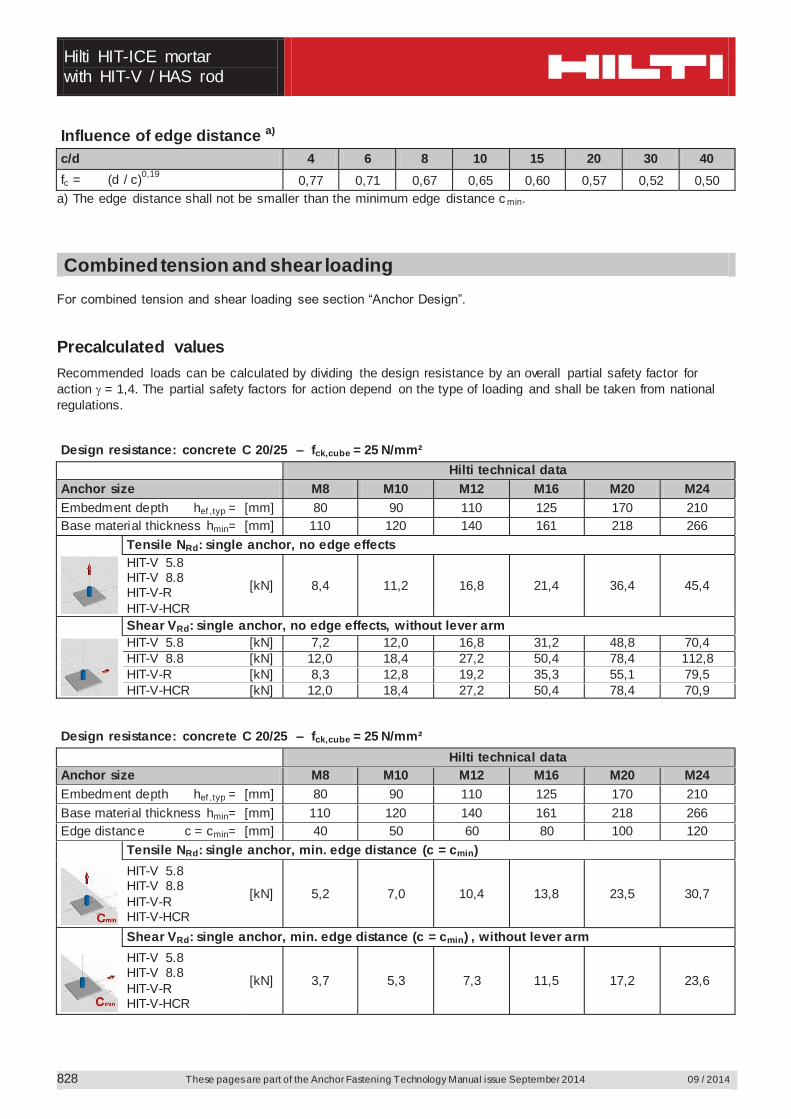
Influence of edge distance a)
c/d 4 6 8 10 15 20 30 40 fc = (d / c)0,19 0,77 0,71 0,67 0,65 0,60 0,57 0,52 0,50
a) The edge distance shall not be smaller than the minimum edge distance c min.
Combined tension and shear loading For combined tension and shear loading see section “Anchor Design”. Precalculated values Recommended loads can be calculated by dividing the design resistance by an overall partial safety factor for action = 1,4. The partial safety factors for action depend on the type of loading and shall be taken from national regulations. Design resistance: concrete C 20/25 – fck,cube = 25 N/mm² Hilti technical data Anchor size M8 M10 M12 M16 M20 M24 Embedment depth hef ,typ = [mm] 80 90 110 125 170 210 Base material thickness hmin= [mm] 110 120 140 161 218 266
Tensile NRd: single anchor, no edge effects HIT-V 5.8 HIT-V 8.8 HIT-V-R HIT-V-HCR
[kN] 8,4 11,2 16,8 21,4 36,4 45,4
Shear VRd: single anchor, no edge effects, without lever arm HIT-V 5.8 [kN] 7,2 12,0 16,8 31,2 48,8 70,4 HIT-V 8.8 [kN] 12,0 18,4 27,2 50,4 78,4 112,8 HIT-V-R [kN] 8,3 12,8 19,2 35,3 55,1 79,5 HIT-V-HCR [kN] 12,0 18,4 27,2 50,4 78,4 70,9
Design resistance: concrete C 20/25 – fck,cube = 25 N/mm² Hilti technical data Anchor size M8 M10 M12 M16 M20 M24 Embedment depth hef ,typ = [mm] 80 90 110 125 170 210 Base material thickness hmin= [mm] 110 120 140 161 218 266 Edge distance c = cmin= [mm] 40 50 60 80 100 120
Tensile NRd: single anchor, min. edge distance (c = cmin) HIT-V 5.8 HIT-V 8.8 HIT-V-R HIT-V-HCR
[kN] 5,2 7,0 10,4 13,8 23,5 30,7
Shear VRd: single anchor, min. edge distance (c = cmin) , without lever arm HIT-V 5.8 HIT-V 8.8 HIT-V-R HIT-V-HCR
[kN] 3,7 5,3 7,3 11,5 17,2 23,6
Hilti HIT-ICE mortar
with HIT-V / HAS rod
09 / 2014 These pages are part of the Anchor Fastening Technology Manual issue September 2014
829
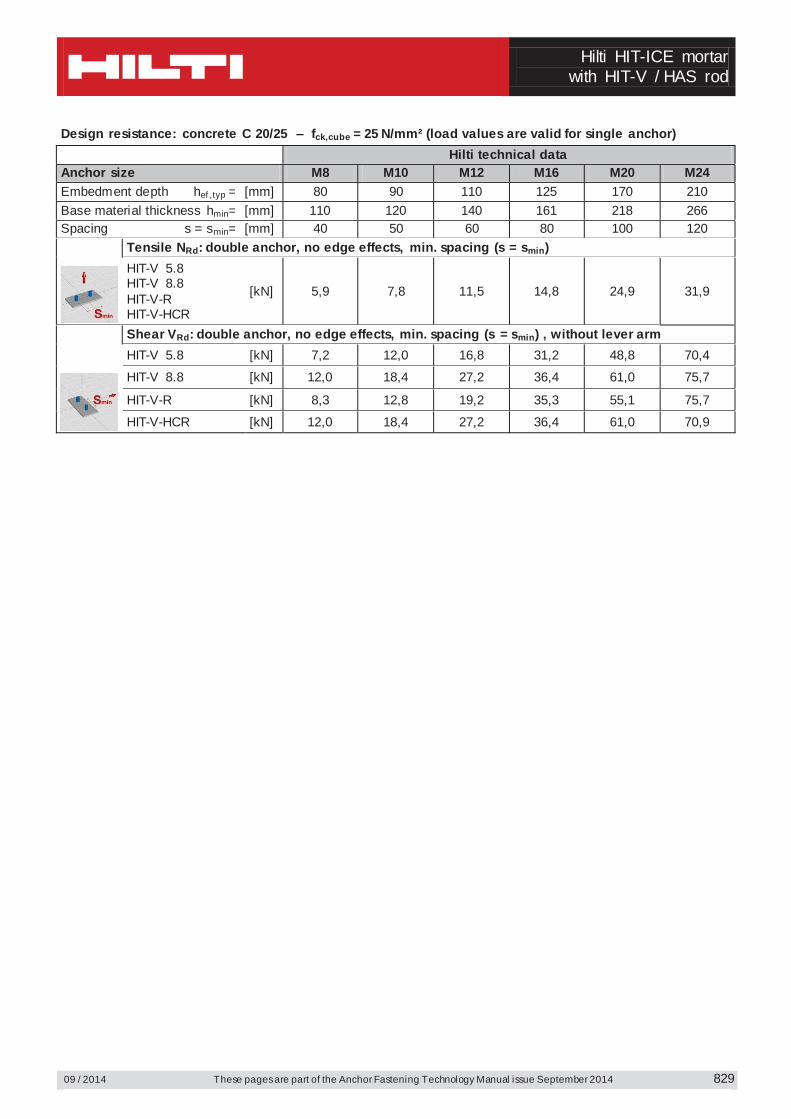
Design resistance: concrete C 20/25 – fck,cube = 25 N/mm² (load values are valid for single anchor) Hilti technical data Anchor size M8 M10 M12 M16 M20 M24 Embedment depth hef ,typ = [mm] 80 90 110 125 170 210 Base material thickness hmin= [mm] 110 120 140 161 218 266 Spacing s = smin= [mm] 40 50 60 80 100 120
Tensile NRd: double anchor, no edge effects, min. spacing (s = smin) HIT-V 5.8 HIT-V 8.8 HIT-V-R HIT-V-HCR
[kN] 5,9 7,8 11,5 14,8 24,9 31,9
Shear VRd: double anchor, no edge effects, min. spacing (s = smin) , without lever arm HIT-V 5.8 [kN] 7,2 12,0 16,8 31,2 48,8 70,4
HIT-V 8.8 [kN] 12,0 18,4 27,2 36,4 61,0 75,7
HIT-V-R [kN] 8,3 12,8 19,2 35,3 55,1 75,7
HIT-V-HCR [kN] 12,0 18,4 27,2 36,4 61,0 70,9
Hilti HIT-ICE mortar with HIS-(R)N sleeve
These pages are part of the Anchor Fastening Technology Manual issue September 2014 09 / 2014 830
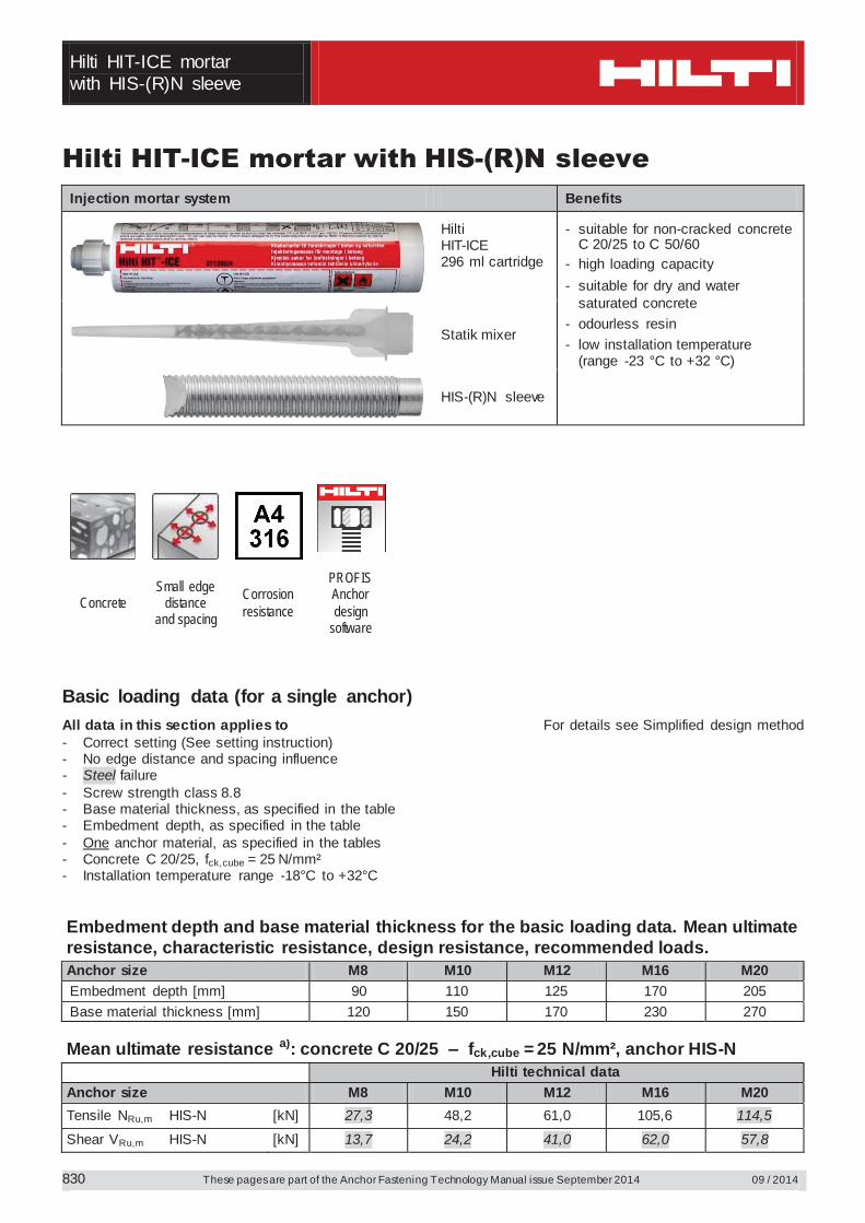
Hilti HIT-ICE mortar with HIS-(R)N sleeve Injection mortar system Benefits
Hilti HIT-ICE 296 ml cartridge
- suitable for non-cracked concrete C 20/25 to C 50/60
- high loading capacity - suitable for dry and water
saturated concrete - odourless resin - low installation temperature
(range -23 °C to +32 °C)
Statik mixer
HIS-(R)N sleeve
Concrete Small edge
distance and spacing
Corrosion resistance
PROFIS Anchor design
software
Basic loading data (for a single anchor) All data in this section applies to For details see Simplified design method - Correct setting (See setting instruction) - No edge distance and spacing influence - Steel failure - Screw strength class 8.8 - Base material thickness, as specified in the table - Embedment depth, as specified in the table - One anchor material, as specified in the tables - Concrete C 20/25, fck,cube = 25 N/mm² - Installation temperature range -18°C to +32°C Embedment depth and base material thickness for the basic loading data. Mean ultimate resistance, characteristic resistance, design resistance, recommended loads. Anchor size M8 M10 M12 M16 M20 Embedment depth [mm] 90 110 125 170 205 Base material thickness [mm] 120 150 170 230 270
Mean ultimate resistance a): concrete C 20/25 – fck,cube = 25 N/mm², anchor HIS-N Hilti technical data Anchor size M8 M10 M12 M16 M20 Tensile NRu,m HIS-N [kN] 27,3 48,2 61,0 105,6 114,5
Shear VRu,m HIS-N [kN] 13,7 24,2 41,0 62,0 57,8
Hilti HIT-ICE mortar
with HIS-(R)N sleeve
09 / 2014 These pages are part of the Anchor Fastening Technology Manual issue September 2014
831
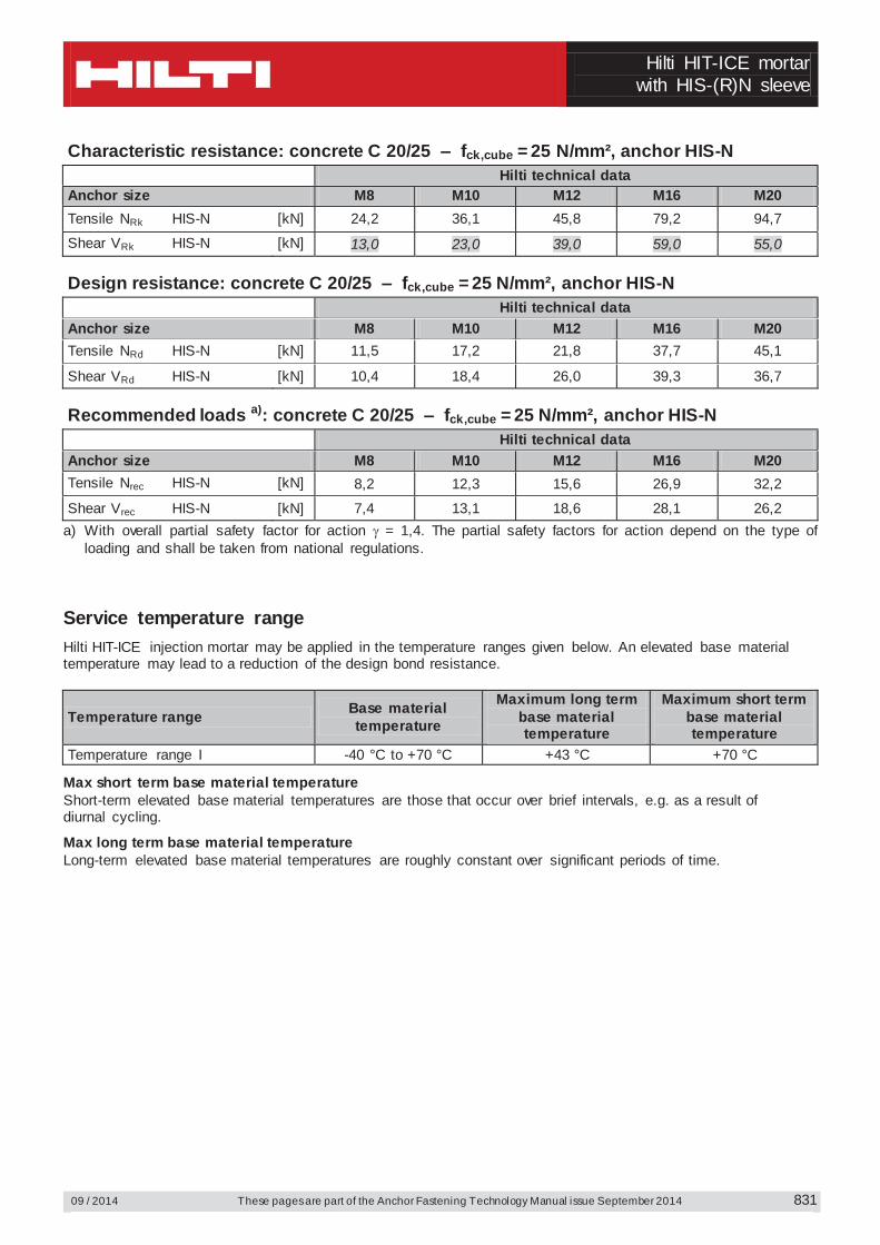
Characteristic resistance: concrete C 20/25 – fck,cube = 25 N/mm², anchor HIS-N Hilti technical data Anchor size M8 M10 M12 M16 M20 Tensile NRk HIS-N [kN] 24,2 36,1 45,8 79,2 94,7
Shear VRk HIS-N [kN] 13,0 23,0 39,0 59,0 55,0 Design resistance: concrete C 20/25 – fck,cube = 25 N/mm², anchor HIS-N Hilti technical data Anchor size M8 M10 M12 M16 M20 Tensile NRd HIS-N [kN] 11,5 17,2 21,8 37,7 45,1
Shear VRd HIS-N [kN] 10,4 18,4 26,0 39,3 36,7 Recommended loads a): concrete C 20/25 – fck,cube = 25 N/mm², anchor HIS-N Hilti technical data Anchor size M8 M10 M12 M16 M20 Tensile Nrec HIS-N [kN] 8,2 12,3 15,6 26,9 32,2
Shear Vrec HIS-N [kN] 7,4 13,1 18,6 28,1 26,2 a) With overall partial safety factor for action = 1,4. The partial safety factors for action depend on the type of
loading and shall be taken from national regulations. Service temperature range Hilti HIT-ICE injection mortar may be applied in the temperature ranges given below. An elevated base material temperature may lead to a reduction of the design bond resistance.
Temperature range Base material temperature
Maximum long term base material temperature
Maximum short term base material temperature
Temperature range I -40 °C to +70 °C +43 °C +70 °C
Max short term base material temperature Short-term elevated base material temperatures are those that occur over brief intervals, e.g. as a result of diurnal cycling.
Max long term base material temperature Long-term elevated base material temperatures are roughly constant over significant periods of time.
Hilti HIT-ICE mortar with HIS-(R)N sleeve
These pages are part of the Anchor Fastening Technology Manual issue September 2014 09 / 2014
832
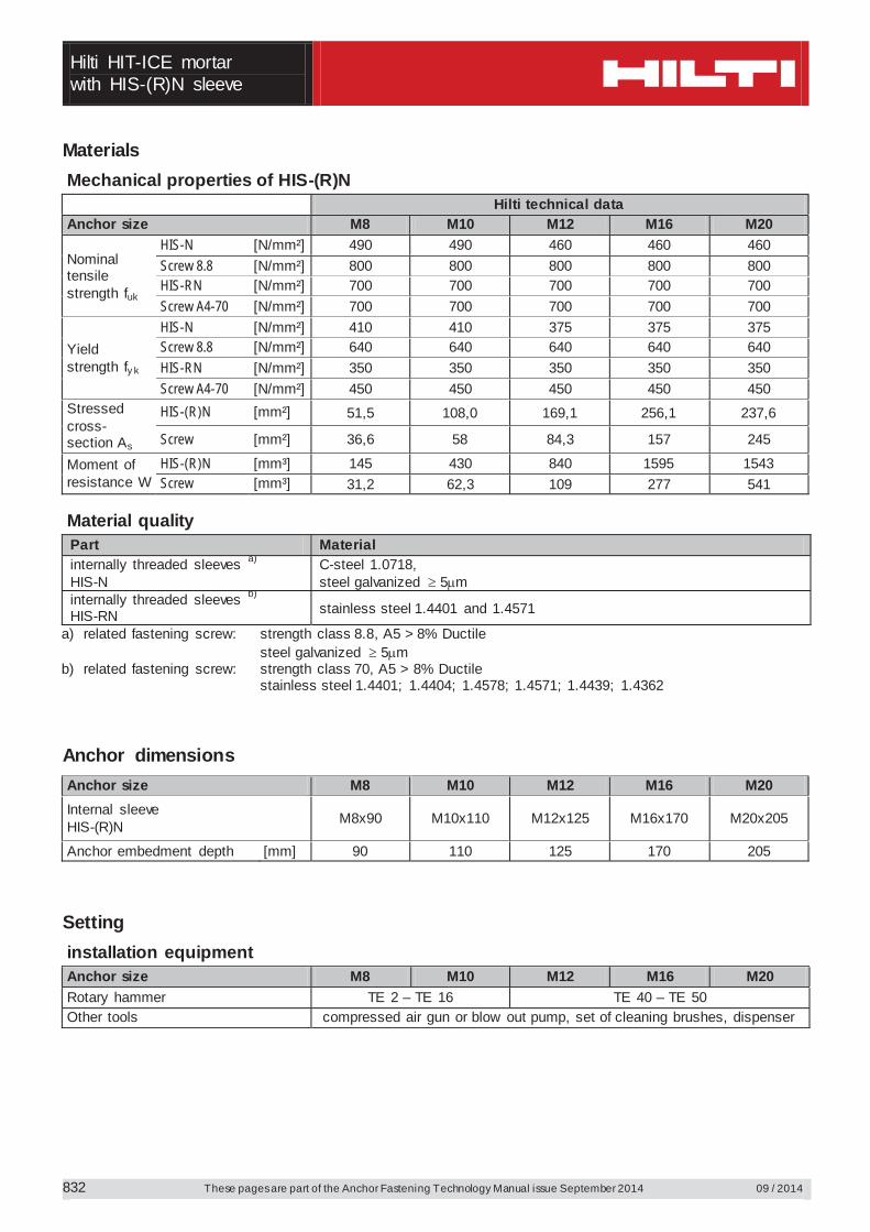
Materials Mechanical properties of HIS-(R)N Hilti technical data Anchor size M8 M10 M12 M16 M20
Nominal tensile strength fuk
HIS-N [N/mm²] 490 490 460 460 460 Screw 8.8 [N/mm²] 800 800 800 800 800 HIS-RN [N/mm²] 700 700 700 700 700 Screw A4-70 [N/mm²] 700 700 700 700 700
Yield strength fy k
HIS-N [N/mm²] 410 410 375 375 375 Screw 8.8 [N/mm²] 640 640 640 640 640 HIS-RN [N/mm²] 350 350 350 350 350 Screw A4-70 [N/mm²] 450 450 450 450 450
Stressed cross-section As
HIS-(R)N [mm²] 51,5 108,0 169,1 256,1 237,6
Screw [mm²] 36,6 58 84,3 157 245
Moment of resistance W
HIS-(R)N [mm³] 145 430 840 1595 1543 Screw [mm³] 31,2 62,3 109 277 541
Material quality Part Material internally threaded sleeves a)
HIS-N C-steel 1.0718, steel galvanized 5 m
internally threaded sleeves b) HIS-RN stainless steel 1.4401 and 1.4571
a) related fastening screw: strength class 8.8, A5 > 8% Ductile steel galvanized 5 m
b) related fastening screw: strength class 70, A5 > 8% Ductile stainless steel 1.4401; 1.4404; 1.4578; 1.4571; 1.4439; 1.4362
Anchor dimensions Anchor size M8 M10 M12 M16 M20 Internal sleeve HIS-(R)N M8x90 M10x110 M12x125 M16x170 M20x205
Anchor embedment depth [mm] 90 110 125 170 205 Setting installation equipment Anchor size M8 M10 M12 M16 M20 Rotary hammer TE 2 – TE 16 TE 40 – TE 50 Other tools compressed air gun or blow out pump, set of cleaning brushes, dispenser

Hilti HIT-ICE mortar
with HIS-(R)N sleeve
09 / 2014 These pages are part of the Anchor Fastening Technology Manual issue September 2014
833
Setting instruction Dry and water-saturated concrete, hammer drilling
a)
a) Note: Manual cleaning for HIS-(R)N M8 and HIS-(R)N M10 only! Brush bore hole with required steel brush HIT-RB For detailed information on installation see instruction for use given with the package of the product.
Hilti HIT-ICE mortar with HIS-(R)N sleeve
These pages are part of the Anchor Fastening Technology Manual issue September 2014 09 / 2014
834
Curing time for general conditions Hilti technical data
Temperature of the base material
Curing time before anchor can be fully loaded tcure
Working time in which anchor can be inserted and adjusted tgel
32 °C 35 min 1 min 21 °C 45 min 2,5 min 16 °C 1 h 5 min 4 °C 1 ½ h 15 min
- 7 °C 6 h 1 h - 18 °C 24 h 1,5 h - 23 °C 36 h 1,5 h
Hilti HIT-ICE mortar
with HIS-(R)N sleeve
09 / 2014 These pages are part of the Anchor Fastening Technology Manual issue September 2014
835
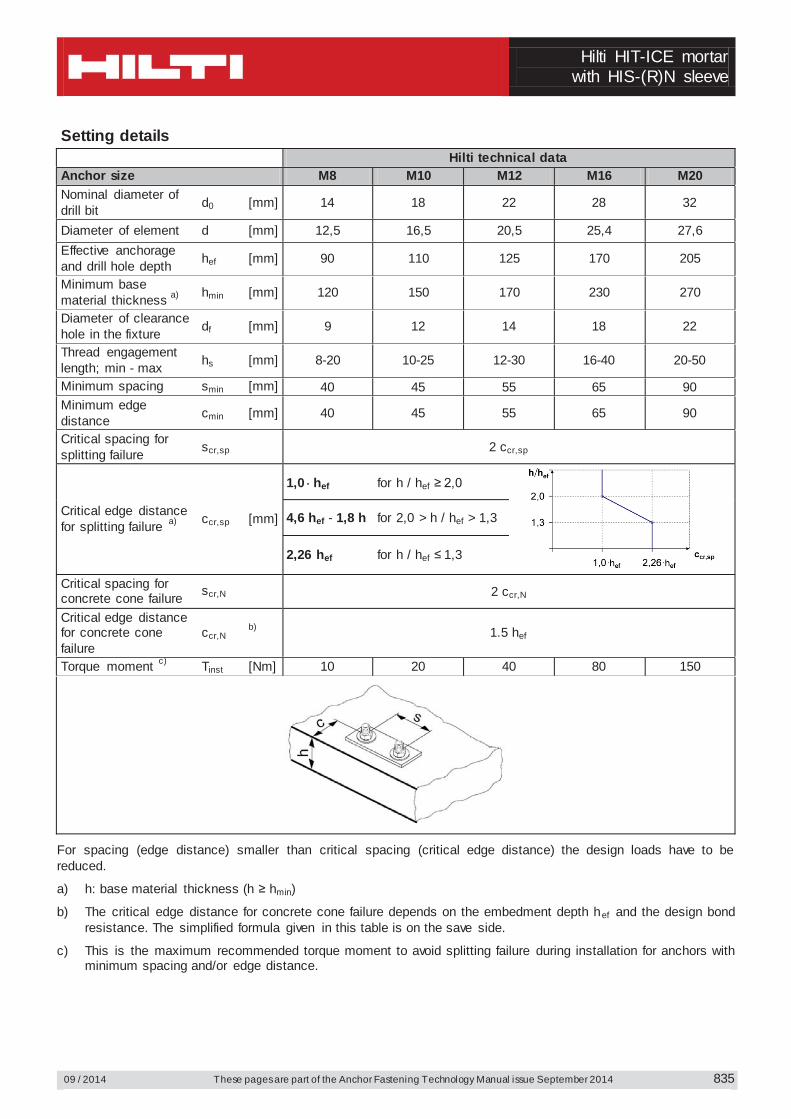
Setting details Hilti technical data Anchor size M8 M10 M12 M16 M20 Nominal diameter of drill bit d0 [mm] 14 18 22 28 32
Diameter of element d [mm] 12,5 16,5 20,5 25,4 27,6 Effective anchorage and drill hole depth hef [mm] 90 110 125 170 205
Minimum base material thickness a) hmin [mm] 120 150 170 230 270
Diameter of clearance hole in the fixture df [mm] 9 12 14 18 22
Thread engagement length; min - max hs [mm] 8-20 10-25 12-30 16-40 20-50
Minimum spacing smin [mm] 40 45 55 65 90 Minimum edge distance cmin [mm] 40 45 55 65 90
Critical spacing for splitting failure scr,sp 2 ccr,sp
Critical edge distance for splitting failure a) ccr,sp [mm]
1,0 hef for h / hef ≥ 2,0
4,6 hef - 1,8 h for 2,0 > h / hef > 1,3
2,26 hef for h / hef ≤ 1,3
Critical spacing for concrete cone failure scr,N 2 ccr,N
Critical edge distance for concrete cone failure
ccr,N b) 1.5 hef
Torque moment c) Tinst [Nm] 10 20 40 80 150
For spacing (edge distance) smaller than critical spacing (critical edge distance) the design loads have to be reduced.
a) h: base material thickness (h ≥ hmin)
b) The critical edge distance for concrete cone failure depends on the embedment depth hef and the design bond resistance. The simplified formula given in this table is on the save side.
c) This is the maximum recommended torque moment to avoid splitting failure during installation for anchors with minimum spacing and/or edge distance.
Hilti HIT-ICE mortar with HIS-(R)N sleeve
These pages are part of the Anchor Fastening Technology Manual issue September 2014 09 / 2014
836
Simplified design method Simplified version of the design method according ETAG 001, TR 029. Design resistance according data given by Hilti.
Influence of concrete strength Influence of edge distance Influence of spacing Valid for a group of two anchors. (The method may also be applied for anchor groups with more than two
anchors or more than one edge distance. The influencing factors must then be considered for each edge distance and spacing. The calculated design loads are then on the save side: They will be lower than the exact values according ETAG 001, TR 029. To avoid this, it is recommended to use the anchor design software PROFIS anchor)
The design method is based on the following simplification: No different loads are acting on individual anchors (no eccentricity)
The values are valid for one anchor. For more complex fastening applications please use the anchor design software PROFIS Anchor.
Tension loading
The design tensile resistance is the lower value of - Steel resistance: NRd,s
- Combined pull-out and concrete cone resistance: NRd,p = N0
Rd,p fB,p f1,N f2,N f3,N fh,p fre,N
- Concrete cone resistance: NRd,c = N0Rd,c fB f1,N f2,N f3,N fh,N fre,N
- Concrete splitting resistance (only non-cracked concrete): NRd,sp = N0
Rd,c fB f1,sp f2,sp f3,sp fh,N fre,N
Basic design tensile resistance
Design steel resistance NRd,s Hilti technical data Anchor size M8 M10 M12 M16 M20
NRd,s HIS-N [kN] 17,4 30,7 44,7 80,3 74,1 HIS-RN [kN] 13,9 21,9 31,6 58,8 69,2
Design combined pull-out and concrete cone resistance NRd,p = N0
Rd,p fB,p f1,N f2,N f3,N fh,p fre,N Hilti technical data Anchor size M8 M10 M12 M16 M20 Embedment depth hef [mm] 90 110 125 170 205 N0
Rd,p Temperature range I [kN] 11,5 17,2 21,8 37,7 45,1
Hilti HIT-ICE mortar
with HIS-(R)N sleeve
09 / 2014 These pages are part of the Anchor Fastening Technology Manual issue September 2014
837
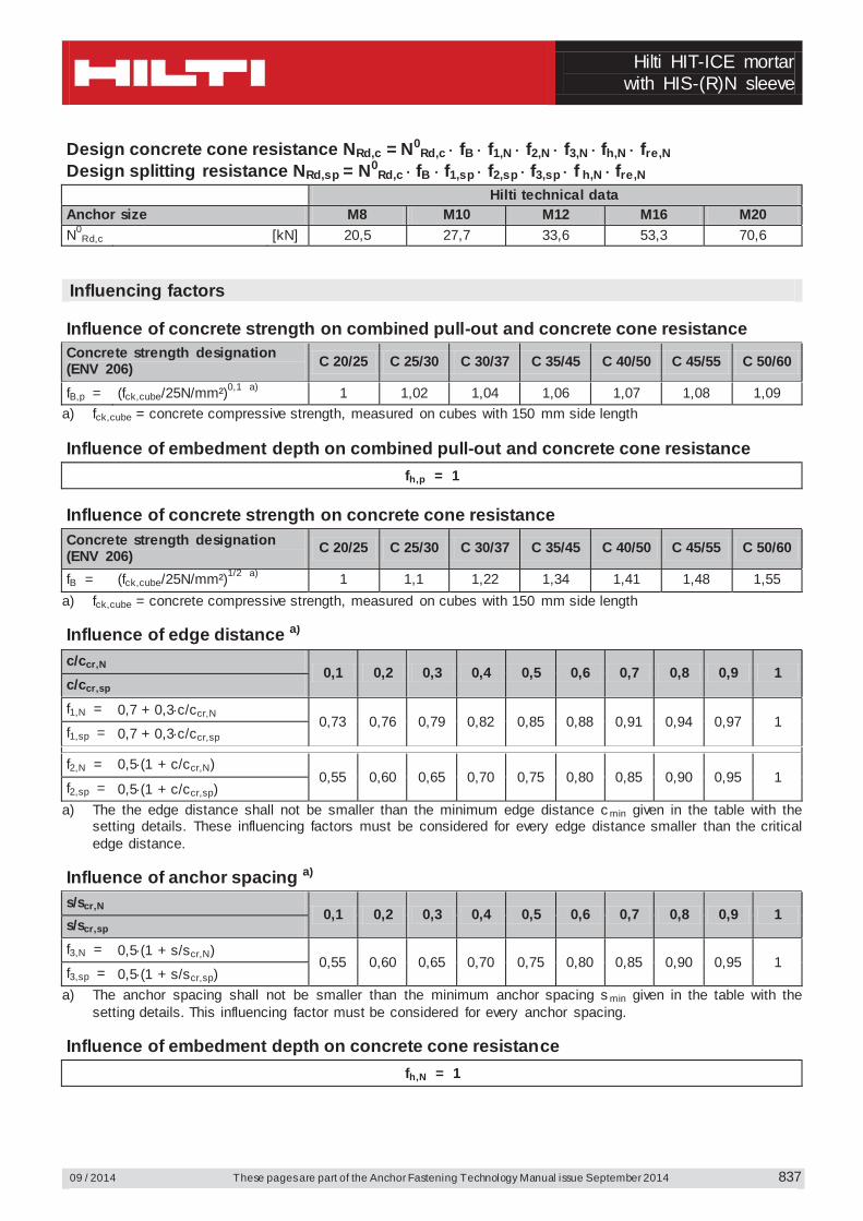
Design concrete cone resistance NRd,c = N0Rd,c fB f1,N f2,N f3,N fh,N fre,N
Design splitting resistance NRd,sp = N0Rd,c fB f1,sp f2,sp f3,sp f h,N fre,N
Hilti technical data Anchor size M8 M10 M12 M16 M20 N0
Rd,c [kN] 20,5 27,7 33,6 53,3 70,6 Influencing factors
Influence of concrete strength on combined pull-out and concrete cone resistance Concrete strength designation (ENV 206) C 20/25 C 25/30 C 30/37 C 35/45 C 40/50 C 45/55 C 50/60
fB,p = (fck,cube/25N/mm²)0,1 a) 1 1,02 1,04 1,06 1,07 1,08 1,09 a) fck,cube = concrete compressive strength, measured on cubes with 150 mm side length Influence of embedment depth on combined pull-out and concrete cone resistance
fh,p = 1
Influence of concrete strength on concrete cone resistance
Concrete strength designation (ENV 206) C 20/25 C 25/30 C 30/37 C 35/45 C 40/50 C 45/55 C 50/60
fB = (fck,cube/25N/mm²)1/2 a) 1 1,1 1,22 1,34 1,41 1,48 1,55 a) fck,cube = concrete compressive strength, measured on cubes with 150 mm side length Influence of edge distance a)
c/ccr,N 0,1 0,2 0,3 0,4 0,5 0,6 0,7 0,8 0,9 1
c/ccr,sp f1,N = 0,7 + 0,3 c/ccr,N
0,73 0,76 0,79 0,82 0,85 0,88 0,91 0,94 0,97 1 f1,sp = 0,7 + 0,3 c/ccr,sp
f2,N = 0,5 (1 + c/ccr,N)
0,55 0,60 0,65 0,70 0,75 0,80 0,85 0,90 0,95 1 f2,sp = 0,5 (1 + c/ccr,sp)
a) The the edge distance shall not be smaller than the minimum edge distance c min given in the table with the setting details. These influencing factors must be considered for every edge distance smaller than the critical edge distance.
Influence of anchor spacing a)
s/scr,N 0,1 0,2 0,3 0,4 0,5 0,6 0,7 0,8 0,9 1
s/scr,sp f3,N = 0,5 (1 + s/scr,N)
0,55 0,60 0,65 0,70 0,75 0,80 0,85 0,90 0,95 1 f3,sp = 0,5 (1 + s/scr,sp)
a) The anchor spacing shall not be smaller than the minimum anchor spacing s min given in the table with the setting details. This influencing factor must be considered for every anchor spacing.
Influence of embedment depth on concrete cone resistance
fh,N = 1
Hilti HIT-ICE mortar with HIS-(R)N sleeve
These pages are part of the Anchor Fastening Technology Manual issue September 2014 09 / 2014
838
Influence of reinforcement hef [mm] 80 90 ≥ 100 fre,N = 0.5 + hef /200mm ≤ 1 0.9 a) 0.95 a) 1
a) This factor applies only for dense reinforcement. If in the area of anchorage there is reinforcement with a spacing ≥ 150 mm (any diameter) or with a diameter ≤ 10 mm and a spacing ≥ 100 mm, then a factor fre,N = 1 may be applied.
Shear loading
The design shear resistance is the lower value of - Steel resistance: VRd,s
- Concrete pryout resistance: VRd,cp = k lower value of NRd,p and NRd,c
- Concrete edge resistance: VRd,c = V0Rd,c fB fß f h f4 f hef fc
Basic design shear resistance
Design steel resistance VRd,s Hilti technical data Anchor size M8 M10 M12 M16 M20
VRd,s HIS-N [kN] 10,4 18,4 26,0 39,3 36,7 HIS-RN [kN] 8,3 12,8 19,2 35,3 41,5
Design concrete pryout resistance VRd,cp = lower value a) of k NRd,p and k NRd,c
k = 1 for hef < 60 mm k = 2 for hef ≥ 60 mm
a) NRd,p: Design combined pull-out and concrete cone resistance NRd,c: Design concrete cone resistance
Design concrete edge resistance VRd,c = V0
Rd,c fB fß f h f4 f hef fc Anchor size M8 M10 M12 M16 M20 Non-cracked concrete V0
Rd,c [kN] 12,4 19,6 28,2 40,2 46,2 Influencing factors
Influence of concrete strength
Concrete strength designation (ENV 206) C 20/25 C 25/30 C 30/37 C 35/45 C 40/50 C 45/55 C 50/60
fB = (fck,cube/25N/mm²)1/2 a) 1 1,1 1,22 1,34 1,41 1,48 1,55 a) fck,cube = concrete compressive strength, measured on cubes with 150 mm side length
Hilti HIT-ICE mortar
with HIS-(R)N sleeve
09 / 2014 These pages are part of the Anchor Fastening Technology Manual issue September 2014
839
Influence of angle between load applied and the direction perpendicular to the free edge
Angle ß 0° 10° 20° 30° 40° 50° 60° 70° 80° ≥ 90°
22
5,2sincos
1
VV
f
1 1,01 1,05 1,13 1,24 1,40 1,64 1,97 2,32 2,50
Influence of base material thickness
h/c 0,15 0,3 0,45 0,6 0,75 0,9 1,05 1,2 1,35 ≥ 1,5 f h = {h/(1,5 c)} 1/2 ≤ 1 0,32 0,45 0,55 0,63 0,71 0,77 0,84 0,89 0,95 1,00
Influence of anchor spacing and edge distance a) for concrete edge resistance: f4 f4 = (c/hef)1,5 (1 + s / [3 c]) 0,5
c/hef Single anchor
Group of two anchors s/hef 0,75 1,50 2,25 3,00 3,75 4,50 5,25 6,00 6,75 7,50 8,25 9,00 9,75 10,50 11,25
0,50 0,35 0,27 0,35 0,35 0,35 0,35 0,35 0,35 0,35 0,35 0,35 0,35 0,35 0,35 0,35 0,35 0,75 0,65 0,43 0,54 0,65 0,65 0,65 0,65 0,65 0,65 0,65 0,65 0,65 0,65 0,65 0,65 0,65 1,00 1,00 0,63 0,75 0,88 1,00 1,00 1,00 1,00 1,00 1,00 1,00 1,00 1,00 1,00 1,00 1,00 1,25 1,40 0,84 0,98 1,12 1,26 1,40 1,40 1,40 1,40 1,40 1,40 1,40 1,40 1,40 1,40 1,40 1,50 1,84 1,07 1,22 1,38 1,53 1,68 1,84 1,84 1,84 1,84 1,84 1,84 1,84 1,84 1,84 1,84 1,75 2,32 1,32 1,49 1,65 1,82 1,98 2,15 2,32 2,32 2,32 2,32 2,32 2,32 2,32 2,32 2,32 2,00 2,83 1,59 1,77 1,94 2,12 2,30 2,47 2,65 2,83 2,83 2,83 2,83 2,83 2,83 2,83 2,83 2,25 3,38 1,88 2,06 2,25 2,44 2,63 2,81 3,00 3,19 3,38 3,38 3,38 3,38 3,38 3,38 3,38 2,50 3,95 2,17 2,37 2,57 2,77 2,96 3,16 3,36 3,56 3,76 3,95 3,95 3,95 3,95 3,95 3,95 2,75 4,56 2,49 2,69 2,90 3,11 3,32 3,52 3,73 3,94 4,15 4,35 4,56 4,56 4,56 4,56 4,56 3,00 5,20 2,81 3,03 3,25 3,46 3,68 3,90 4,11 4,33 4,55 4,76 4,98 5,20 5,20 5,20 5,20 3,25 5,86 3,15 3,38 3,61 3,83 4,06 4,28 4,51 4,73 4,96 5,18 5,41 5,63 5,86 5,86 5,86 3,50 6,55 3,51 3,74 3,98 4,21 4,44 4,68 4,91 5,14 5,38 5,61 5,85 6,08 6,31 6,55 6,55 3,75 7,26 3,87 4,12 4,36 4,60 4,84 5,08 5,33 5,57 5,81 6,05 6,29 6,54 6,78 7,02 7,26 4,00 8,00 4,25 4,50 4,75 5,00 5,25 5,50 5,75 6,00 6,25 6,50 6,75 7,00 7,25 7,50 7,75 4,25 8,76 4,64 4,90 5,15 5,41 5,67 5,93 6,18 6,44 6,70 6,96 7,22 7,47 7,73 7,99 8,25 4,50 9,55 5,04 5,30 5,57 5,83 6,10 6,36 6,63 6,89 7,16 7,42 7,69 7,95 8,22 8,49 8,75 4,75 10,35 5,45 5,72 5,99 6,27 6,54 6,81 7,08 7,36 7,63 7,90 8,17 8,45 8,72 8,99 9,26 5,00 11,18 5,87 6,15 6,43 6,71 6,99 7,27 7,55 7,83 8,11 8,39 8,66 8,94 9,22 9,50 9,78 5,25 12,03 6,30 6,59 6,87 7,16 7,45 7,73 8,02 8,31 8,59 8,88 9,17 9,45 9,74 10,02 10,31 5,50 12,90 6,74 7,04 7,33 7,62 7,92 8,21 8,50 8,79 9,09 9,38 9,67 9,97 10,26 10,55 10,85
a) The anchor spacing and the edge distance shall not be smaller than the minimum anchor spacing s min and the minimum edge distance cmin. Influence of embedment depth
Anchor size M8 M10 M12 M16 M20 f hef = 1,38 1,21 1,04 1,22 1,45
Influence of edge distance a)
c/d 4 6 8 10 15 20 30 40 fc = (d / c)0,19 0,77 0,71 0,67 0,65 0,60 0,57 0,52 0,50
a) The edge distance shall not be smaller than the minimum edge distance c min.
Hilti HIT-ICE mortar with HIS-(R)N sleeve
These pages are part of the Anchor Fastening Technology Manual issue September 2014 09 / 2014
840
Combined tension and shear loading For combined tension and shear loading see section “Anchor Design”. Precalculated values Recommended loads can be calculated by dividing the design resistance by an overall partial safety factor for action = 1,4. The partial safety factors for action depend on the type of loading and shall be taken from national regulations. Design resistance: concrete C 20/25 – fck,cube = 25 N/mm² Hilti technical data Anchor size M8 M10 M12 M16 M20 Embedment depth hef = [mm] 90 110 125 170 205 Base material thickness hmin= [mm] 120 150 170 230 270
Tensile NRd: single anchor, no edge effects
HIS-(R)N [kN] 11,5 17,2 21,8 37,7 45,1
Shear VRd: single anchor, no edge effects, without lever arm HIS-N [kN] 10,4 18,4 26,0 39,3 36,7
HIS-RN [kN] 8,3 12,8 19,2 35,3 41,5 Design resistance: concrete C 20/25 – fck,cube = 25 N/mm² Hilti technical data Anchor size M8 M10 M12 M16 M20 Embedment depth hef = [mm] 90 110 125 170 205 Base material thickness hmin= [mm] 120 150 170 230 270 Edge distance c = cmin= [mm] 40 45 55 65 90
Tensile NRd: single anchor, min. edge distance (c = cmin)
HIS-(R)N [kN] 6,1 8,8 11,3 19,1 25,5
Shear VRd: single anchor, min. edge distance (c = cmin) , without lever arm
HIS-(R)N [kN] 4,2 5,5 7,6 10,8 17,2
Design resistance: concrete C 20/25 – fck,cube = 25 N/mm² (load values are valid for single anchor) Hilti technical data Anchor size M8 M10 M12 M16 M20 Embedment depth hef = [mm] 90 110 125 170 205 Base material thickness hmin= [mm] 120 150 170 230 270 Spacing s = smin= [mm] 40 45 55 65 90
Tensile NRd: double anchor, no edge effects, min. spacing (s = smin)
HIS-(R)N [kN] 7,7 11,2 14,1 23,8 29,9
Shear VRd: double anchor, no edge effects, min. spacing (s = smin) , without lever arm HIS-N [kN] 10,4 18,4 26,0 39,3 36,7
HIS-RN [kN] 8,3 12,8 19,2 35,3 41,5
Hilti HIT-ICE mortar
with HIS-(R)N sleeve
09 / 2014 These pages are part of the Anchor Fastening Technology Manual issue September 2014
841
Hilti HIT-ICE mortar with rebar (as anchor)
These pages are part of the Anchor Fastening Technology Manual issue September 2014 09 / 2014 842
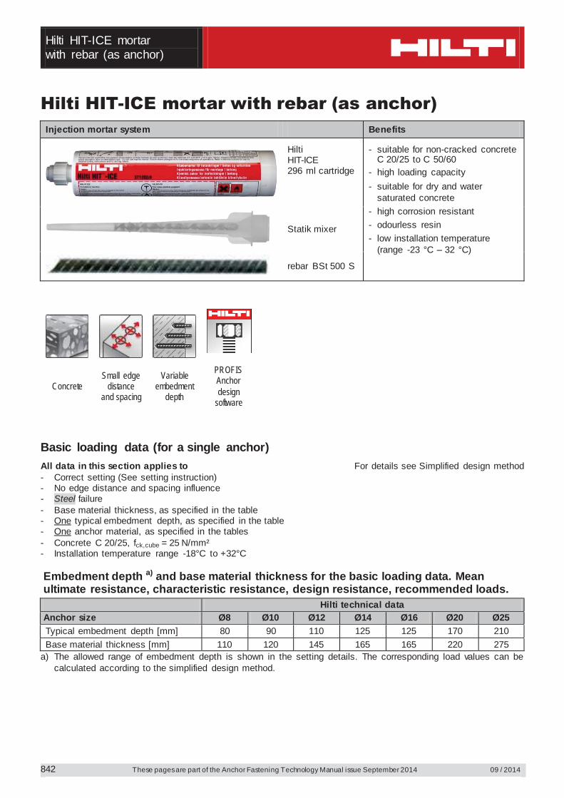
Hilti HIT-ICE mortar with rebar (as anchor) Injection mortar system Benefits
Hilti HIT-ICE 296 ml cartridge
- suitable for non-cracked concrete C 20/25 to C 50/60
- high loading capacity - suitable for dry and water
saturated concrete - high corrosion resistant - odourless resin - low installation temperature
(range -23 °C – 32 °C)
Statik mixer
rebar BSt 500 S
Concrete Small edge
distance and spacing
Variable embedment
depth
PROFIS Anchor design
software
Basic loading data (for a single anchor) All data in this section applies to For details see Simplified design method - Correct setting (See setting instruction) - No edge distance and spacing influence - Steel failure - Base material thickness, as specified in the table- One typical embedment depth, as specified in the table - One anchor material, as specified in the tables - Concrete C 20/25, fck,cube = 25 N/mm² - Installation temperature range -18°C to +32°C Embedment depth a) and base material thickness for the basic loading data. Mean ultimate resistance, characteristic resistance, design resistance, recommended loads. Hilti technical data Anchor size Ø8 Ø10 Ø12 Ø14 Ø16 Ø20 Ø25 Typical embedment depth [mm] 80 90 110 125 125 170 210 Base material thickness [mm] 110 120 145 165 165 220 275
a) The allowed range of embedment depth is shown in the setting details. The corresponding load values can be calculated according to the simplified design method.
Hilti HIT-ICE mortar
with rebar (as anchor)
09 / 2014 These pages are part of the Anchor Fastening Technology Manual issue September 2014
843
Mean ultimate resistance: concrete C 20/25 – fck,cube = 25 N/mm², anchor rebar BSt 500S Hilti technical data Anchor size Ø8 Ø10 Ø12 Ø14 Ø16 Ø20 Ø25 Tensile NRu,m BSt 500 S [kN] 20,2 28,3 40,0 51,8 63,6 84,6 105,8
Shear VRu,m BSt 500 S [kN] 14,7 23,1 32,6 44,1 57,8 90,3 141,8 Characteristic resistance: concrete C 20/25 – fck,cube = 25 N/mm², anchor rebar BSt 500 S Hilti technical data Anchor size Ø8 Ø10 Ø12 Ø14 Ø16 Ø20 Ø25 Tensile NRk BSt 500 S [kN] 15,1 21,2 30,0 38,9 47,7 63,4 79,4
Shear VRk BSt 500 S [kN] 14,0 22,0 31,0 42,0 55,0 86,0 135,0 Design resistance: concrete C 20/25 – fck,cube = 25 N/mm², anchor rebar BSt 500 S Hilti technical data Anchor size Ø8 Ø10 Ø12 Ø14 Ø16 Ø20 Ø25 Tensile NRd BSt 500 S [kN] 7,2 10,1 14,3 18,5 22,7 30,2 37,8
Shear VRd BSt 500 S [kN] 9,3 14,7 20,7 28,0 36,7 57,3 90,0 Recommended loads a): concrete C 20/25 – fck,cube = 25 N/mm², anchor rebar BSt 500 S Hilti technical data Anchor size Ø8 Ø10 Ø12 Ø14 Ø16 Ø20 Ø25 Tensile Nrec BSt 500 S [kN] 5,1 7,2 10,2 13,2 16,2 21,6 27,0
Shear Vrec BSt 500 S [kN] 6,7 10,5 14,8 20,0 26,2 41,0 64,3 a) With overall partial safety factor for action = 1,4. The partial safety factors for action depend on the type of
loading and shall be taken from national regulations. Service temperature range Hilti HIT-ICE injection mortar may be applied in the temperature ranges given below. An elevated base material temperature may lead to a reduction of the design bond resistance.
Temperature range Base material temperature
Maximum long term base material temperature
Maximum short term base material temperature
Temperature range I -40 °C to +40 °C +43 °C +70 °C
Max short term base material temperature Short-term elevated base material temperatures are those that occur over brief intervals, e.g. as a result of diurnal cycling.
Max long term base material temperature Long-term elevated base material temperatures are roughly constant over significant periods of time.
Hilti HIT-ICE mortar with rebar (as anchor)
These pages are part of the Anchor Fastening Technology Manual issue September 2014 09 / 2014
844
Materials Mechanical properties of rebar BSt 500S Hilti technical data Anchor size Ø8 Ø10 Ø12 Ø14 Ø16 Ø20 Ø25 Nominal tensile strength fuk
BSt 500 S [N/mm²] 550 550 550 550 550 550 550
Yield strength fy k
[N/mm²] 500 500 500 500 500 500 500
Stressed cross-section As
BSt 500 S [mm²] 50,3 78,5 113,1 153,9 201,1 314,2 490,9
Moment of resistance W
BSt 500 S [mm³] 50,3 98,2 169,6 269,4 402,1 785,4 1534
Material quality Part Material rebar BSt 500 S
Geometry and mechanical properties according to DIN 488-2:1986 or E DIN 488-2:2006
Setting installation equipment Anchor size Ø8 Ø10 Ø12 Ø14 Ø16 Ø20 Ø25 Rotary hammer TE 2 – TE 16 TE 40 – TE 70 Other tools compressed air gun or blow out pump, set of cleaning brushes, dispenser
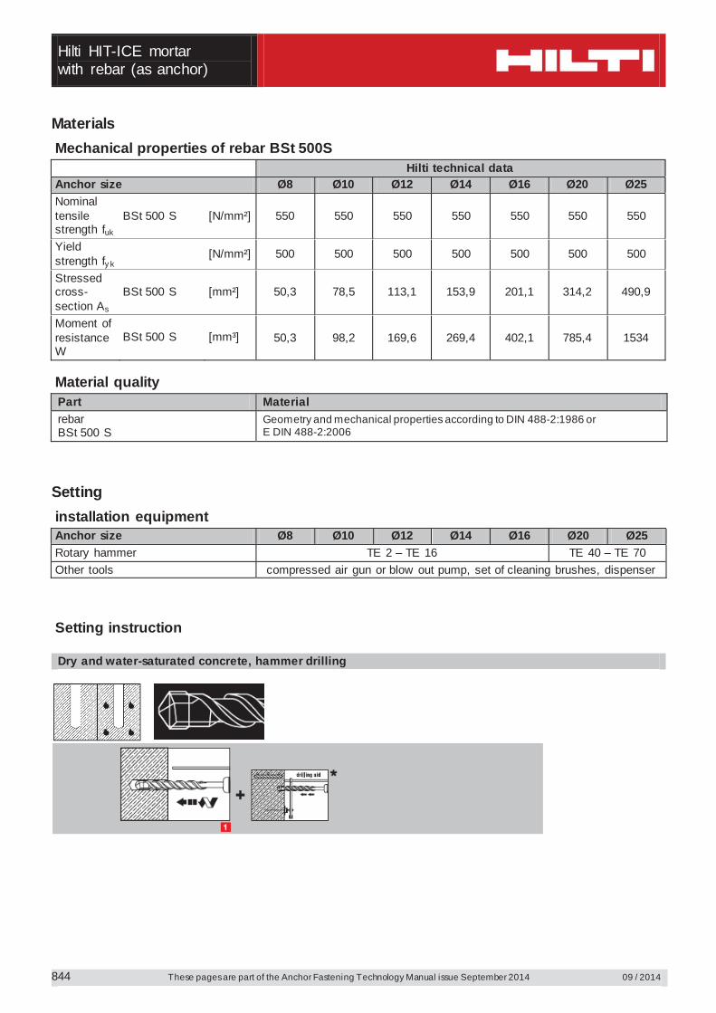
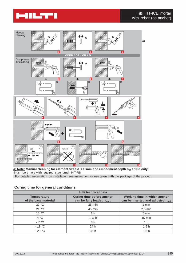
Setting instruction
Dry and water-saturated concrete, hammer drilling
Hilti HIT-ICE mortar
with rebar (as anchor)
09 / 2014 These pages are part of the Anchor Fastening Technology Manual issue September 2014
845
a)
a) Note: Manual cleaning for element sizes d 16mm and embedment depth hef 10 d only! Brush bore hole with required steel brush HIT-RB For detailed information on installation see instruction for use given with the package of the product.
Curing time for general conditions
Hilti technical data Temperature
of the base material Curing time before anchor can be fully loaded tcure
Working time in which anchor can be inserted and adjusted tgel
32 °C 35 min 1 min 21 °C 45 min 2,5 min 16 °C 1 h 5 min 4 °C 1 ½ h 15 min
- 7 °C 6 h 1 h - 18 °C 24 h 1,5 h - 23 °C 36 h 1,5 h
Hilti HIT-ICE mortar with rebar (as anchor)
These pages are part of the Anchor Fastening Technology Manual issue September 2014 09 / 2014
846
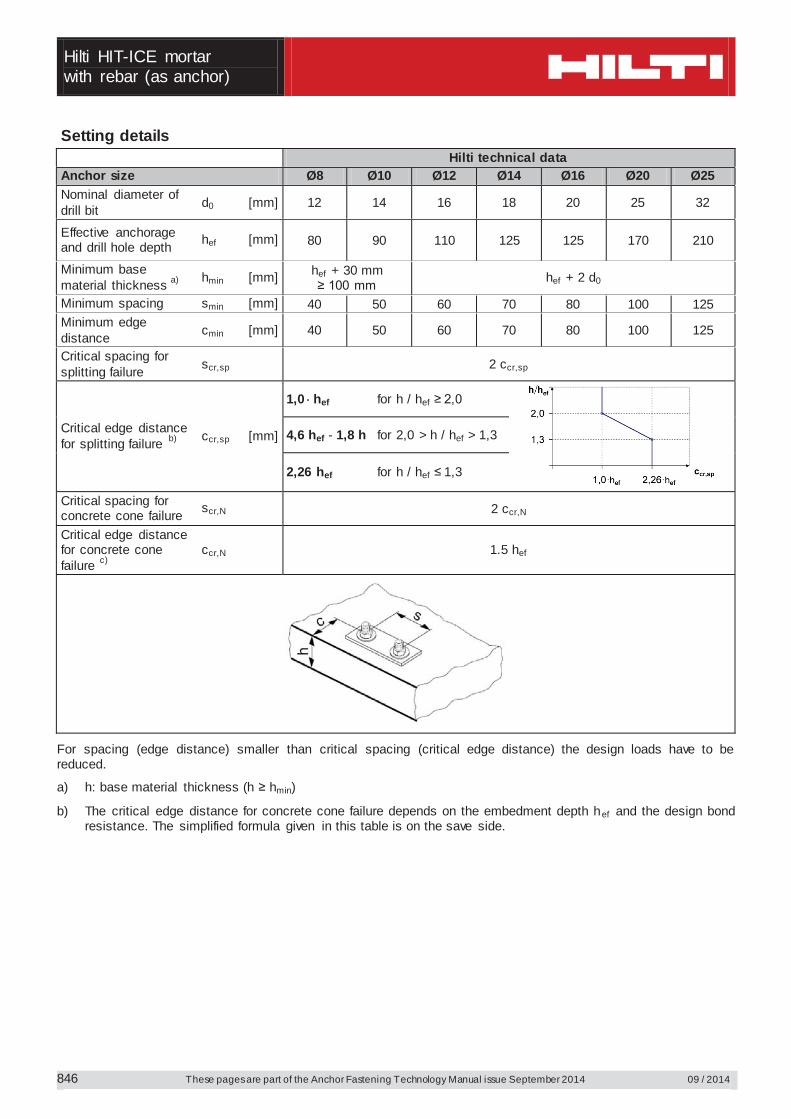
Setting details Hilti technical data Anchor size Ø8 Ø10 Ø12 Ø14 Ø16 Ø20 Ø25 Nominal diameter of drill bit d0 [mm] 12 14 16 18 20 25 32
Effective anchorage and drill hole depth hef [mm] 80 90 110 125 125 170 210
Minimum base material thickness a) hmin [mm] hef + 30 mm
≥ 100 mm hef + 2 d0
Minimum spacing smin [mm] 40 50 60 70 80 100 125 Minimum edge distance cmin [mm] 40 50 60 70 80 100 125
Critical spacing for splitting failure scr,sp 2 ccr,sp
Critical edge distance for splitting failure b) ccr,sp [mm]
1,0 hef for h / hef ≥ 2,0
4,6 hef - 1,8 h for 2,0 > h / hef > 1,3
2,26 hef for h / hef ≤ 1,3
Critical spacing for concrete cone failure scr,N 2 ccr,N
Critical edge distance for concrete cone failure c)
ccr,N 1.5 hef
For spacing (edge distance) smaller than critical spacing (critical edge distance) the design loads have to be reduced.
a) h: base material thickness (h ≥ hmin)
b) The critical edge distance for concrete cone failure depends on the embedment depth hef and the design bond resistance. The simplified formula given in this table is on the save side.
Hilti HIT-ICE mortar
with rebar (as anchor)
09 / 2014 These pages are part of the Anchor Fastening Technology Manual issue September 2014
847
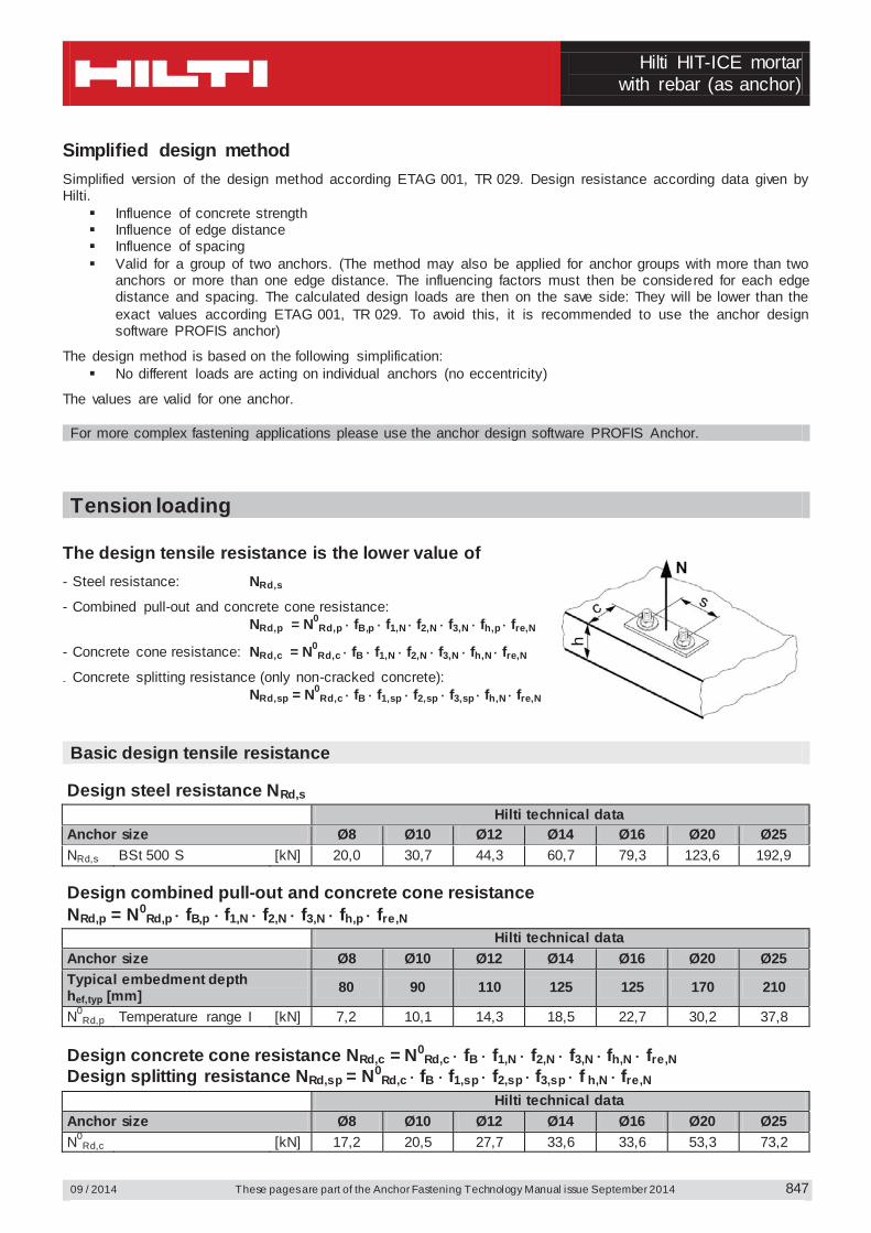
Simplified design method Simplified version of the design method according ETAG 001, TR 029. Design resistance according data given by Hilti.
Influence of concrete strength Influence of edge distance Influence of spacing Valid for a group of two anchors. (The method may also be applied for anchor groups with more than two
anchors or more than one edge distance. The influencing factors must then be considered for each edge distance and spacing. The calculated design loads are then on the save side: They will be lower than the exact values according ETAG 001, TR 029. To avoid this, it is recommended to use the anchor design software PROFIS anchor)
The design method is based on the following simplification: No different loads are acting on individual anchors (no eccentricity)
The values are valid for one anchor. For more complex fastening applications please use the anchor design software PROFIS Anchor.
Tension loading
The design tensile resistance is the lower value of - Steel resistance: NRd,s
- Combined pull-out and concrete cone resistance: NRd,p = N0
Rd,p fB,p f1,N f2,N f3,N fh,p fre,N
- Concrete cone resistance: NRd,c = N0Rd,c fB f1,N f2,N f3,N fh,N fre,N
- Concrete splitting resistance (only non-cracked concrete): NRd,sp = N0
Rd,c fB f1,sp f2,sp f3,sp fh,N fre,N
Basic design tensile resistance
Design steel resistance NRd,s Hilti technical data Anchor size Ø8 Ø10 Ø12 Ø14 Ø16 Ø20 Ø25 NRd,s BSt 500 S [kN] 20,0 30,7 44,3 60,7 79,3 123,6 192,9
Design combined pull-out and concrete cone resistance NRd,p = N0
Rd,p fB,p f1,N f2,N f3,N fh,p fre,N Hilti technical data Anchor size Ø8 Ø10 Ø12 Ø14 Ø16 Ø20 Ø25 Typical embedment depth hef,typ [mm] 80 90 110 125 125 170 210
N0Rd,p Temperature range I [kN] 7,2 10,1 14,3 18,5 22,7 30,2 37,8
Design concrete cone resistance NRd,c = N0
Rd,c fB f1,N f2,N f3,N fh,N fre,N Design splitting resistance NRd,sp = N0
Rd,c fB f1,sp f2,sp f3,sp f h,N fre,N Hilti technical data Anchor size Ø8 Ø10 Ø12 Ø14 Ø16 Ø20 Ø25 N0
Rd,c [kN] 17,2 20,5 27,7 33,6 33,6 53,3 73,2
Hilti HIT-ICE mortar with rebar (as anchor)
These pages are part of the Anchor Fastening Technology Manual issue September 2014 09 / 2014
848
Influencing factors Influence of concrete strength on combined pull-out and concrete cone resistance
Concrete strength designation (ENV 206) C 20/25 C 25/30 C 30/37 C 35/45 C 40/50 C 45/55 C 50/60
fB,p = (fck,cube/25N/mm²)0,1 a) 1 1,02 1,04 1,06 1,07 1,08 1,09 a) fck,cube = concrete compressive strength, measured on cubes with 150 mm side length Influence of embedment depth on combined pull-out and concrete cone resistance
fh,p = 1
Influence of concrete strength on concrete cone resistance
Concrete strength designation (ENV 206) C 20/25 C 25/30 C 30/37 C 35/45 C 40/50 C 45/55 C 50/60
fB = (fck,cube/25N/mm²)1/2 a) 1 1,1 1,22 1,34 1,41 1,48 1,55 a) fck,cube = concrete compressive strength, measured on cubes with 150 mm side length Influence of embedment depth on concrete cone resistance
fh,N = 1
Influence of edge distance a)
c/ccr,N 0,1 0,2 0,3 0,4 0,5 0,6 0,7 0,8 0,9 1
c/ccr,sp f1,N = 0,7 + 0,3 c/ccr,N
0,73 0,76 0,79 0,82 0,85 0,88 0,91 0,94 0,97 1 f1,sp = 0,7 + 0,3 c/ccr,sp
f2,N = 0,5 (1 + c/ccr,N)
0,55 0,60 0,65 0,70 0,75 0,80 0,85 0,90 0,95 1 f2,sp = 0,5 (1 + c/ccr,sp)
a) The the edge distance shall not be smaller than the minimum edge distance c min given in the table with the setting details. These influencing factors must be considered for every edge distance smaller than the critical edge distance.
Influence of anchor spacing a)
s/scr,N 0,1 0,2 0,3 0,4 0,5 0,6 0,7 0,8 0,9 1
s/scr,sp f3,N = 0,5 (1 + s/scr,N)
0,55 0,60 0,65 0,70 0,75 0,80 0,85 0,90 0,95 1 f3,sp = 0,5 (1 + s/scr,sp)
a) The anchor spacing shall not be smaller than the minimum anchor spacing s min given in the table with the setting details. This influencing factor must be considered for every anchor spacing.
Influence of reinforcement hef [mm] 80 90 ≥ 100 fre,N = 0.5 + hef /200mm ≤ 1 0,9 a) 0,95 a) 1
a) This factor applies only for dense reinforcement. If in the area of anchorage there is reinforcement with a spacing ≥ 150 mm (any diameter) or with a diameter ≤ 10 mm and a spacing ≥ 100 mm, then a factor fre,N = 1 may be applied.
Hilti HIT-ICE mortar
with rebar (as anchor)
09 / 2014 These pages are part of the Anchor Fastening Technology Manual issue September 2014
849
Shear loading
The design shear resistance is the lower value of - Steel resistance: VRd,s
- Concrete pryout resistance: VRd,cp = k lower value of NRd,p and NRd,c
- Concrete edge resistance: VRd,c = V0Rd,c fB fß f h f4 f hef fc
Basic design shear resistance
Design steel resistance VRd,s Hilti technical data Anchor size Ø8 Ø10 Ø12 Ø14 Ø16 Ø20 Ø25 VRd,s BSt 500 S [kN] 9,3 14,7 20,7 28,0 36,7 57,3 90,0
Design concrete pryout resistance VRd,cp = lower value a) of k NRd,p and k NRd,c
k = 2
a) NRd,p: Design combined pull-out and concrete cone resistance NRd,c: Design concrete cone resistance
Design concrete edge resistance VRd,c = V0
Rd,c fB fß f h f4 f hef fc Anchor size Ø8 Ø10 Ø12 Ø14 Ø16 Ø20 Ø25 Non-cracked concrete V0
Rd,c [kN] 5,9 8,6 11,6 15,0 18,7 27,0 39,2 Influencing factors
Influence of concrete strength
Concrete strength designation (ENV 206) C 20/25 C 25/30 C 30/37 C 35/45 C 40/50 C 45/55 C 50/60
fB = (fck,cube/25N/mm²)1/2 a) 1 1,1 1,22 1,34 1,41 1,48 1,55 a) fck,cube = concrete compressive strength, measured on cubes with 150 mm side length Influence of angle between load applied and the direction perpendicular to the free edge
Angle ß 0° 10° 20° 30° 40° 50° 60° 70° 80° ≥ 90°
22
5,2sincos
1
VV
f
1 1,01 1,05 1,13 1,24 1,40 1,64 1,97 2,32 2,50
Influence of base material thickness
h/c 0,15 0,3 0,45 0,6 0,75 0,9 1,05 1,2 1,35 ≥ 1,5 f h = {h/(1,5 c)} 1/2 ≤ 1 0,32 0,45 0,55 0,63 0,71 0,77 0,84 0,89 0,95 1,00
Hilti HIT-ICE mortar with rebar (as anchor)
These pages are part of the Anchor Fastening Technology Manual issue September 2014 09 / 2014
850
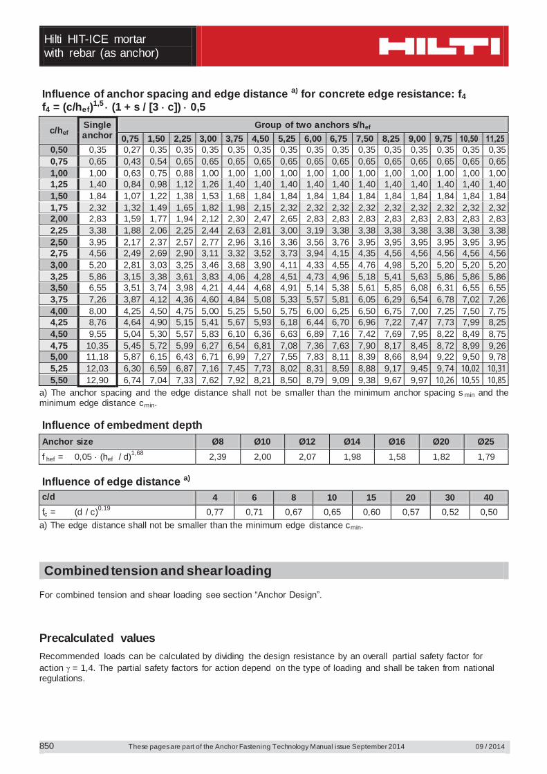
Influence of anchor spacing and edge distance a) for concrete edge resistance: f4 f4 = (c/hef)1,5 (1 + s / [3 c]) 0,5
c/hef Single anchor
Group of two anchors s/hef 0,75 1,50 2,25 3,00 3,75 4,50 5,25 6,00 6,75 7,50 8,25 9,00 9,75 10,50 11,25
0,50 0,35 0,27 0,35 0,35 0,35 0,35 0,35 0,35 0,35 0,35 0,35 0,35 0,35 0,35 0,35 0,35 0,75 0,65 0,43 0,54 0,65 0,65 0,65 0,65 0,65 0,65 0,65 0,65 0,65 0,65 0,65 0,65 0,65 1,00 1,00 0,63 0,75 0,88 1,00 1,00 1,00 1,00 1,00 1,00 1,00 1,00 1,00 1,00 1,00 1,00 1,25 1,40 0,84 0,98 1,12 1,26 1,40 1,40 1,40 1,40 1,40 1,40 1,40 1,40 1,40 1,40 1,40 1,50 1,84 1,07 1,22 1,38 1,53 1,68 1,84 1,84 1,84 1,84 1,84 1,84 1,84 1,84 1,84 1,84 1,75 2,32 1,32 1,49 1,65 1,82 1,98 2,15 2,32 2,32 2,32 2,32 2,32 2,32 2,32 2,32 2,32 2,00 2,83 1,59 1,77 1,94 2,12 2,30 2,47 2,65 2,83 2,83 2,83 2,83 2,83 2,83 2,83 2,83 2,25 3,38 1,88 2,06 2,25 2,44 2,63 2,81 3,00 3,19 3,38 3,38 3,38 3,38 3,38 3,38 3,38 2,50 3,95 2,17 2,37 2,57 2,77 2,96 3,16 3,36 3,56 3,76 3,95 3,95 3,95 3,95 3,95 3,95 2,75 4,56 2,49 2,69 2,90 3,11 3,32 3,52 3,73 3,94 4,15 4,35 4,56 4,56 4,56 4,56 4,56 3,00 5,20 2,81 3,03 3,25 3,46 3,68 3,90 4,11 4,33 4,55 4,76 4,98 5,20 5,20 5,20 5,20 3,25 5,86 3,15 3,38 3,61 3,83 4,06 4,28 4,51 4,73 4,96 5,18 5,41 5,63 5,86 5,86 5,86 3,50 6,55 3,51 3,74 3,98 4,21 4,44 4,68 4,91 5,14 5,38 5,61 5,85 6,08 6,31 6,55 6,55 3,75 7,26 3,87 4,12 4,36 4,60 4,84 5,08 5,33 5,57 5,81 6,05 6,29 6,54 6,78 7,02 7,26 4,00 8,00 4,25 4,50 4,75 5,00 5,25 5,50 5,75 6,00 6,25 6,50 6,75 7,00 7,25 7,50 7,75 4,25 8,76 4,64 4,90 5,15 5,41 5,67 5,93 6,18 6,44 6,70 6,96 7,22 7,47 7,73 7,99 8,25 4,50 9,55 5,04 5,30 5,57 5,83 6,10 6,36 6,63 6,89 7,16 7,42 7,69 7,95 8,22 8,49 8,75 4,75 10,35 5,45 5,72 5,99 6,27 6,54 6,81 7,08 7,36 7,63 7,90 8,17 8,45 8,72 8,99 9,26 5,00 11,18 5,87 6,15 6,43 6,71 6,99 7,27 7,55 7,83 8,11 8,39 8,66 8,94 9,22 9,50 9,78 5,25 12,03 6,30 6,59 6,87 7,16 7,45 7,73 8,02 8,31 8,59 8,88 9,17 9,45 9,74 10,02 10,31 5,50 12,90 6,74 7,04 7,33 7,62 7,92 8,21 8,50 8,79 9,09 9,38 9,67 9,97 10,26 10,55 10,85
a) The anchor spacing and the edge distance shall not be smaller than the minimum anchor spacing s min and the minimum edge distance cmin. Influence of embedment depth
Anchor size Ø8 Ø10 Ø12 Ø14 Ø16 Ø20 Ø25 f hef = 0,05 (hef / d)1,68 2,39 2,00 2,07 1,98 1,58 1,82 1,79
Influence of edge distance a)
c/d 4 6 8 10 15 20 30 40 fc = (d / c)0,19 0,77 0,71 0,67 0,65 0,60 0,57 0,52 0,50
a) The edge distance shall not be smaller than the minimum edge distance cmin.
Combined tension and shear loading For combined tension and shear loading see section “Anchor Design”. Precalculated values
Recommended loads can be calculated by dividing the design resistance by an overall partial safety factor for action = 1,4. The partial safety factors for action depend on the type of loading and shall be taken from national regulations.
Hilti HIT-ICE mortar
with rebar (as anchor)
09 / 2014 These pages are part of the Anchor Fastening Technology Manual issue September 2014
851
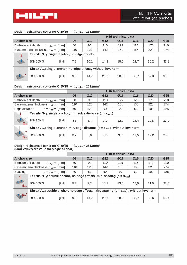
Design resistance: concrete C 20/25 – fck,cube = 25 N/mm² Hilti technical data Anchor size Ø8 Ø10 Ø12 Ø14 Ø16 Ø20 Ø25 Embedment depth hef ,typ = [mm] 80 90 110 125 125 170 210 Base material thickness hmin= [mm] 110 120 142 161 165 220 274
Tensile NRd: single anchor, no edge effects
BSt 500 S [kN] 7,2 10,1 14,3 18,5 22,7 30,2 37,8
Shear VRd: single anchor, no edge effects, without lever arm
BSt 500 S [kN] 9,3 14,7 20,7 28,0 36,7 57,3 90,0
Design resistance: concrete C 20/25 – fck,cube = 25 N/mm² Hilti technical data Anchor size Ø8 Ø10 Ø12 Ø14 Ø16 Ø20 Ø25 Embedment depth hef ,typ = [mm] 80 90 110 125 125 170 210 Base material thickness hmin= [mm] 110 120 142 161 165 220 274 Edge distance c = cmin= [mm] 40 50 60 70 80 100 125
Tensile NRd: single anchor, min. edge distance (c = cmin)
BSt 500 S [kN] 4,6 6,4 9,2 12,0 14,4 20,5 27,2
Shear VRd: single anchor, min. edge distance (c = cmin) , without lever arm
BSt 500 S [kN] 3,7 5,3 7,3 9,5 11,5 17,2 25,0
Design resistance: concrete C 20/25 – fck,cube = 25 N/mm² (load values are valid for single anchor) Hilti technical data Anchor size Ø8 Ø10 Ø12 Ø14 Ø16 Ø20 Ø25 Embedment depth hef ,typ = [mm] 80 90 110 125 125 170 210 Base material thickness hmin= [mm] 110 120 142 161 165 220 274 Spacing s = smin= [mm] 40 50 60 70 80 100 125
Tensile NRd: double anchor, no edge effects, min. spacing (s = smin)
BSt 500 S [kN] 5,2 7,2 10,1 13,0 15,5 21,5 27,6
Shear VRd: double anchor, no edge effects, min. spacing (s = smin) , without lever arm
BSt 500 S [kN] 9,3 14,7 20,7 28,0 36,7 50,6 63,4