Hilti HIT-HY 170 mortar for masonry · Hilti HIT-HY 170 mortar for masonry ... use PROFIS Anchor...
16
1 Oct-17 Hilti HIT-HY 170 mortar for masonry Injection mortar system Benefits - Chemical injection fastening for the most common types of base materials: - Hollow and solid clay bricks, calcium silicate bricks, normal and light weight concrete blocks - Two-component hybrid mortar - Versatile and convenient handling with HDE dispenser - Mortar filing control wit HIT-SC sleeves Hilti HIT-HY 170 500 ml foil pack (also available as 330 ml foil pack) HIT-V (F) HIT-V-R HIT-V-HCR (M8-M12) HIT-IC (M8-M12) HIT-SC composite sleeve (16-22) Base material Load conditions Solid brick Hollow brick Static/ quasi-static Installation conditions Other information Hammer drilled holes Small edge embedment depth Variable embedment depth European Technical Assessment CE conformity Corrosion resistance High corrosion resistance PROFIS Anchor design software a) All data given in this section according to ETA-15/0197, issue 2015-12-09. Approvals / certificates Description Authority / Laboratory No. / date of issue European technical Approval a) DIBt, Berlin, Germany ETA-15/0197 / 2015-12-09 (HIT-HY 200-A)
-
Upload
hoangnguyet -
Category
Documents
-
view
273 -
download
3
Transcript of Hilti HIT-HY 170 mortar for masonry · Hilti HIT-HY 170 mortar for masonry ... use PROFIS Anchor...
1 Oct-17
Hilti HIT-HY 170 mortar for masonry
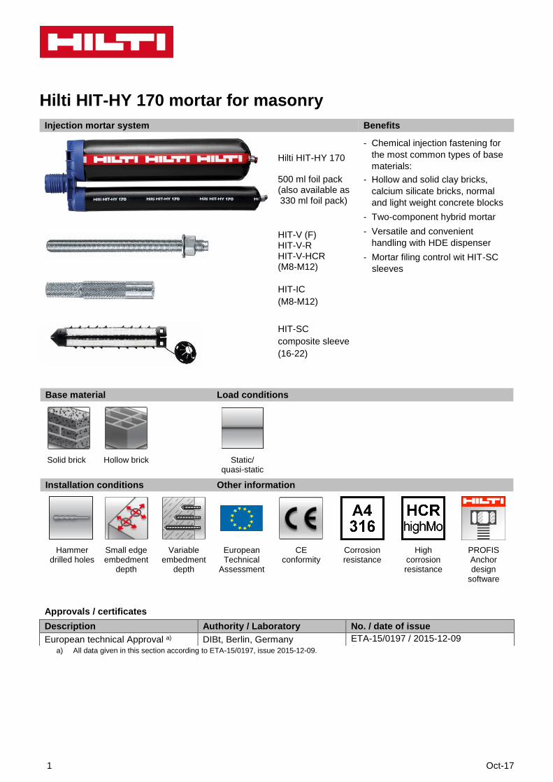
Injection mortar system Benefits
- Chemical injection fastening for
the most common types of base
materials:
- Hollow and solid clay bricks,
calcium silicate bricks, normal
and light weight concrete blocks
- Two-component hybrid mortar
- Versatile and convenient
handling with HDE dispenser
- Mortar filing control wit HIT-SC
sleeves
Hilti HIT-HY 170
500 ml foil pack (also available as 330 ml foil pack)
HIT-V (F) HIT-V-R HIT-V-HCR(M8-M12)
HIT-IC
(M8-M12)
HIT-SC
composite sleeve
(16-22)
Base material Load conditions
Solid brick Hollow brick Static/ quasi-static
Installation conditions Other information
Hammer drilled holes
Small edge embedment
depth
Variable embedment
depth
European Technical
Assessment
CE conformity
Corrosion resistance
High corrosion resistance
PROFIS Anchor design
software
a) All data given in this section according to ETA-15/0197, issue 2015-12-09.
Approvals / certificates
Description Authority / Laboratory No. / date of issue
European technical Approval a) DIBt, Berlin, Germany ETA-15/0197 / 2015-12-09 (HIT-HY 200-A)
Oct-17 2
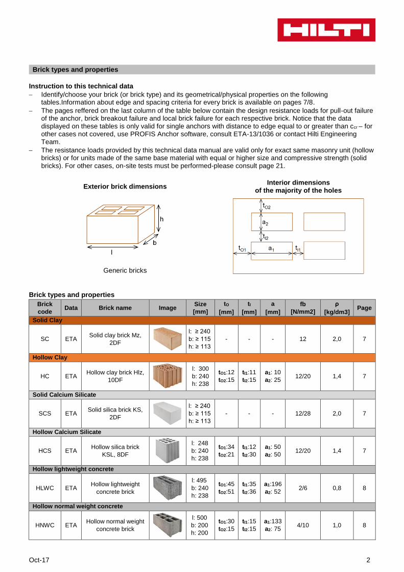
Brick types and properties
Instruction to this technical data
Identify/choose your brick (or brick type) and its geometrical/physical properties on the following tables.Information about edge and spacing criteria for every brick is available on pages 7/8.
The pages reffered on the last column of the table below contain the design resistance loads for pull-out failure of the anchor, brick breakout failure and local brick failure for each respective brick. Notice that the data displayed on these tables is only valid for single anchors with distance to edge equal to or greater than ccr – for other cases not covered, use PROFIS Anchor software, consult ETA-13/1036 or contact Hilti Engineering Team.
The resistance loads provided by this technical data manual are valid only for exact same masonry unit (hollow bricks) or for units made of the same base material with equal or higher size and compressive strength (solid bricks). For other cases, on-site tests must be performed-please consult page 21.
Exterior brick dimensions Interior dimensions
of the majority of the holes
Generic bricks
Brick types and properties
Brick
code Data Brick name Image
Size
[mm]
tO
[mm]
tI
[mm]
a
[mm]
fb
[N/mm2]
ρ
[kg/dm3] Page
Solid Clay
SC ETA Solid clay brick Mz,
2DF
l: ≥ 240
b: ≥ 115
h: ≥ 113
- - - 12 2,0 7
Hollow Clay
HC ETA Hollow clay brick Hlz,
10DF
l: 300
b: 240
h: 238
tO1:12
tO2:15
tI1:11
tI2:15
a1: 10
a2: 25 12/20 1,4 7
Solid Calcium Silicate
SCS ETA Solid silica brick KS,
2DF
l: ≥ 240
b: ≥ 115
h: ≥ 113
- - - 12/28 2,0 7
Hollow Calcium Silicate
HCS ETA Hollow silica brick
KSL, 8DF
l: 248
b: 240
h: 238
tO1:34
tO2:21
tI1:12
tI2:30
a1: 50
a2: 50 12/20 1,4 7
Hollow lightweight concrete
HLWC ETA Hollow lightweight
concrete brick
l: 495
b: 240
h: 238
tO1:45
tO2:51
tI1:35
tI2:36
a1:196
a2: 52 2/6 0,8 8
Hollow normal weight concrete
HNWC ETA Hollow normal weight
concrete brick
l: 500
b: 200
h: 200
tO1:30
tO2:15
tI1:15
tI2:15
a1:133
a2: 75 4/10 1,0 8
3 Oct-17
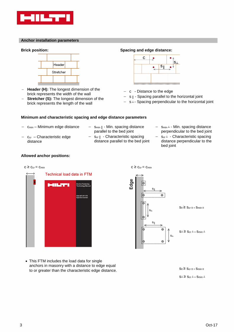
Anchor installation parameters
Brick position: Spacing and edge distance:
Header (H): The longest dimension of the brick represents the width of the wall
Stretcher (S): The longest dimension of the brick represents the length of the wall
c - Distance to the edge s ║ - Spacing parallel to the horizontal joint s ┴ - Spacing perpendicular to the horizontal joint
Minimum and characteristic spacing and edge distance parameters
cmin – Minimum edge distance
ccr – Characteristic edge distance
smin ║ - Min. spacing distance parallel to the bed joint
scr ║ - Characteristic spacing distance parallel to the bed joint
smin ┴ - Min. spacing distance perpendicular to the bed joint
scr ┴ - Characteristic spacing distance perpendicular to the bed joint
Allowed anchor positions:
c ≥ ccr = cmin
This FTM includes the load data for singleanchors in masonry with a distance to edge equal
to or greater than the characteristic edge distance.
c ≥ ccr = cmin
sII ≥ scr II = smin II
s┴ ≥ scr ┴ = smin ┴
sII ≥ scr II = smin II
s┴ ≥ scr ┴ = smin ┴

Oct-17 4
Edge and spacing distances per brick
Brick code cmin= ccr
[mm] sminII= scrII
[mm] smin┴ = scr┴
[mm]
SC 115 240 115
HC 150 300 240
SCS 115 240 115
HCS 125 248 240
HLC 250 240 240
HNC 200 200 200
Anchor dimensions
Anchor size M8 M10 M12
Embedment depth HIT-V-(R, HCR) hef [mm] 80
Embedment depth HIT-IT hef [mm] 80
5 Oct-17
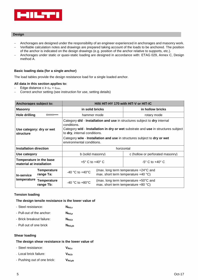
Design
Anchorages are designed under the responsibility of an engineer experienced in anchorages and masonry work.
Verifiable calculation notes and drawings are prepared taking account of the loads to be anchored. The position of the anchor is indicated on the design drawings (e.g. position of the anchor relative to supports, etc.).
Anchorages under static or quasi-static loading are designed in accordance with: ETAG 029, Annex C, Design method A.
Basic loading data (for a single anchor)
The load tables provide the design resistance load for a single loaded anchor.
All data in this section applies to:
Edge distance c ≥ ccr = cmin.
Correct anchor setting (see instruction for use, setting details)
Tension loading
The design tensile resistance is the lower value of
- Steel resistance: NRd,s
- Pull-out of the anchor: NRd,p
- Brick breakout failure: NRd,b
- Pull out of one brick NRd,pb
Shear loading
The design shear resistance is the lower value of
- Steel resistance: VRd,s
- Local brick failure: VRd,b
- Pushing out of one brick: VRd,pb
Anchorages subject to: Hilti HIT-HY 170 with HIT-V or HIT-IC
Masonry in solid bricks in hollow bricks
Hole drilling hammer mode rotary mode
Use category: dry or wet
structure
Category d/d - Installation and use in structures subject to dry internal
conditions.
Category w/d - Installation in dry or wet substrate and use in structures subject
to dry, internal conditions.
Category w/w - Installation and use in structures subject to dry or wet
environmental conditions.
Installation direction horizontal
Use category b (solid masonry) c (hollow or perforated masonry)
Temperature in the base
material at installation +5° C to +40° C -5° C to +40° C
In-service
temperature
Temperature
range Ta: -40 °C to +40°C
(max. long term temperature +24°C and
max. short term temperature +40 °C)
Temperature
range Tb: -40 °C to +80°C
(max. long term temperature +50°C and
max. short term temperature +80 °C)
Oct-17 6
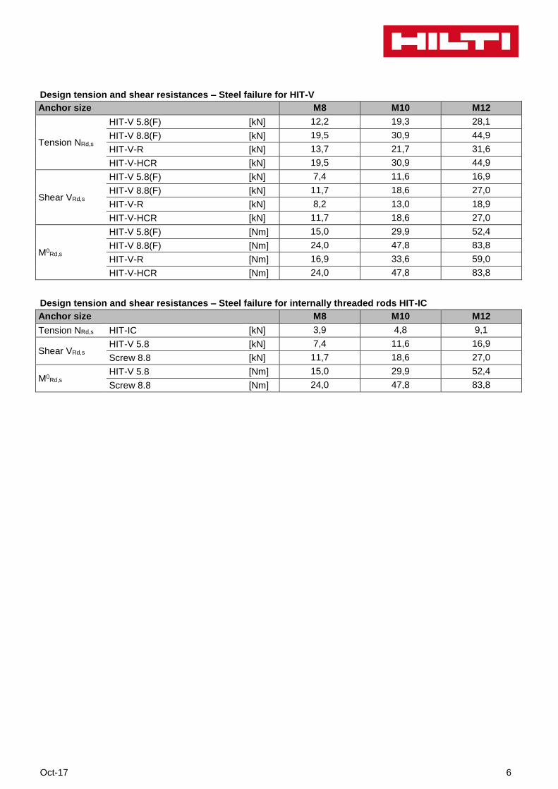
Design tension and shear resistances – Steel failure for HIT-V
Anchor size M8 M10 M12
Tension NRd,s
HIT-V 5.8(F) [kN] 12,2 19,3 28,1
HIT-V 8.8(F) [kN] 19,5 30,9 44,9
HIT-V-R [kN] 13,7 21,7 31,6
HIT-V-HCR [kN] 19,5 30,9 44,9
Shear VRd,s
HIT-V 5.8(F) [kN] 7,4 11,6 16,9
HIT-V 8.8(F) [kN] 11,7 18,6 27,0
HIT-V-R [kN] 8,2 13,0 18,9
HIT-V-HCR [kN] 11,7 18,6 27,0
M0Rd,s
HIT-V 5.8(F) [Nm] 15,0 29,9 52,4
HIT-V 8.8(F) [Nm] 24,0 47,8 83,8
HIT-V-R [Nm] 16,9 33,6 59,0
HIT-V-HCR [Nm] 24,0 47,8 83,8
Design tension and shear resistances – Steel failure for internally threaded rods HIT-IC
Anchor size M8 M10 M12
Tension NRd,s HIT-IC [kN] 3,9 4,8 9,1
Shear VRd,s HIT-V 5.8 [kN] 7,4 11,6 16,9
Screw 8.8 [kN] 11,7 18,6 27,0
M0Rd,s
HIT-V 5.8 [Nm] 15,0 29,9 52,4
Screw 8.8 [Nm] 24,0 47,8 83,8
7 Oct-17
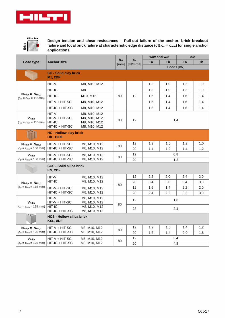
Design tension and shear resistances – Pull-out failure of the anchor, brick breakout
failure and local brick failure at characteristic edge distance (c ≥ ccr = cmin) for single anchor
applications
Load type Anchor size hef
[mm]
fb
[N/mm²]
w/w and w/d d/d
Ta Tb Ta Tb
Loads [kN]
SC - Solid clay brick
Mz, 2DF
NRd,p = NRd,b
(ccr = cmin = 115mm)
HIT-V M8, M10, M12
80 12
1,2 1,0 1,2 1,0
HIT-IC M8 1,2 1,0 1,2 1,0
HIT-IC M10, M12 1,6 1,4 1,6 1,4
HIT-V + HIT-SC M8, M10, M12 1,6 1,4 1,6 1,4
HIT-IC + HIT-SC M8, M10, M12 1,6 1,4 1,6 1,4
VRd,b
(ccr = cmin = 115mm)
HIT-V M8, M10, M12
HIT-V + HIT-SC M8, M10, M12
HIT-IC M8, M10, M12
HIT-IC + HIT-SC M8, M10, M12
80 12 1,4
HC - Hollow clay brick
Hlz, 10DF
NRd,p = NRd,b
(ccr = cmin = 150 mm)
HIT-V + HIT-SC
HIT-IC + HIT-SC
M8, M10, M12
M8, M10, M12 80
12 1,2 1,0 1,2 1,0
20 1,4 1,2 1,4 1,2
VRd,b
(ccr = cmin = 150 mm)
HIT-V + HIT-SC
HIT-IC + HIT-SC
M8, M10, M12
M8, M10, M12 80
12 0,8
20 1,2
SCS - Solid silica brick
KS, 2DF
NRd,p = NRd,b
(ccr = cmin = 115 mm)
HIT-V
HIT-IC
M8, M10, M12
M8, M10, M12 80
12 2,2 2,0 2,4 2,0
28 3,4 3,0 3,4 3,0
HIT-V + HIT-SC
HIT-IC + HIT-SC
M8, M10, M12
M8, M10, M12
12 1,6 1,4 2,2 2,0
28 2,4 2,2 3,2 3,0
VRd,b
(ccr = cmin = 115 mm)
HIT-V
HIT-V + HIT-SC
M8, M10, M12
M8, M10, M12 80
12 1,6
HIT-IC
HIT-IC + HIT-SC
M8, M10, M12
M8, M10, M12 28 2,4
HCS - Hollow silica brick
KSL, 8DF
NRd,p = NRd,b
(ccr = cmin = 125 mm)
HIT-V + HIT-SC
HIT-IC + HIT-SC
M8, M10, M12
M8, M10, M12 80
12 1,2 1,0 1,4 1,2
20 1,6 1,4 2,0 1,8
VRd,b
(ccr = cmin = 125 mm)
HIT-V + HIT-SC
HIT-IC + HIT-SC
M8, M10, M12
M8, M10, M12 80
12 3,4
20 4,8
Oct-17 8
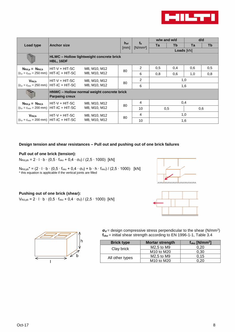
Load type Anchor size hef
[mm]
fb
[N/mm²]
w/w and w/d d/d
Ta Tb Ta Tb
Loads [kN]
HLWC – Hollow lightweight concrete brick
HBL, 16DF
NRd,p = NRd,b
(ccr = cmin = 250 mm)
HIT-V + HIT-SC
HIT-IC + HIT-SC
M8, M10, M12
M8, M10, M12 80
2 0,5 0,4 0,6 0,5
6 0,8 0,6 1,0 0,8
VRd,b
(ccr = cmin = 250 mm)
HIT-V + HIT-SC
HIT-IC + HIT-SC
M8, M10, M12
M8, M10, M12 80
2 1,0
6 1,6
HNWC – Hollow normal weight concrete brick
Parpaing creux
NRd,p = NRd,b
(ccr = cmin = 200 mm)
HIT-V + HIT-SC
HIT-IC + HIT-SC
M8, M10, M12
M8, M10, M12 80
4 0,4
10 0,5 0,6
VRd,b
(ccr = cmin = 200 mm)
HIT-V + HIT-SC
HIT-IC + HIT-SC
M8, M10, M12
M8, M10, M12 80
4 1,0
10 1,6
Design tension and shear resistances – Pull out and pushing out of one brick failures
Pull out of one brick (tension):
NRd,pb = 2 ∙ l ∙ b ∙ (0,5 ∙ fvko + 0,4 ∙ σd) / (2,5 ∙ 1000) [kN] NRd,pb* = (2 ∙ l ∙ b ∙ (0,5 ∙ fvko + 0,4 ∙ σd) + b ∙ h ∙ fvko) / (2,5 ∙ 1000) [kN] * this equation is applicable if the vertical joints are filled
Pushing out of one brick (shear):
VRd,pb = 2 ∙ l ∙ b ∙ (0,5 ∙ fvko + 0,4 ∙ σd) / (2,5 ∙ 1000) [kN]
σd = design compressive stress perpendicular to the shear (N/mm2) fvko = initial shear strength according to EN 1996-1-1, Table 3.4
Brick type Mortar strength fvko [N/mm2]
Clay brick M2,5 to M9 0,20 M10 to M20 0,30
All other types M2,5 to M9 0,15 M10 to M20 0,20
9 Oct-17
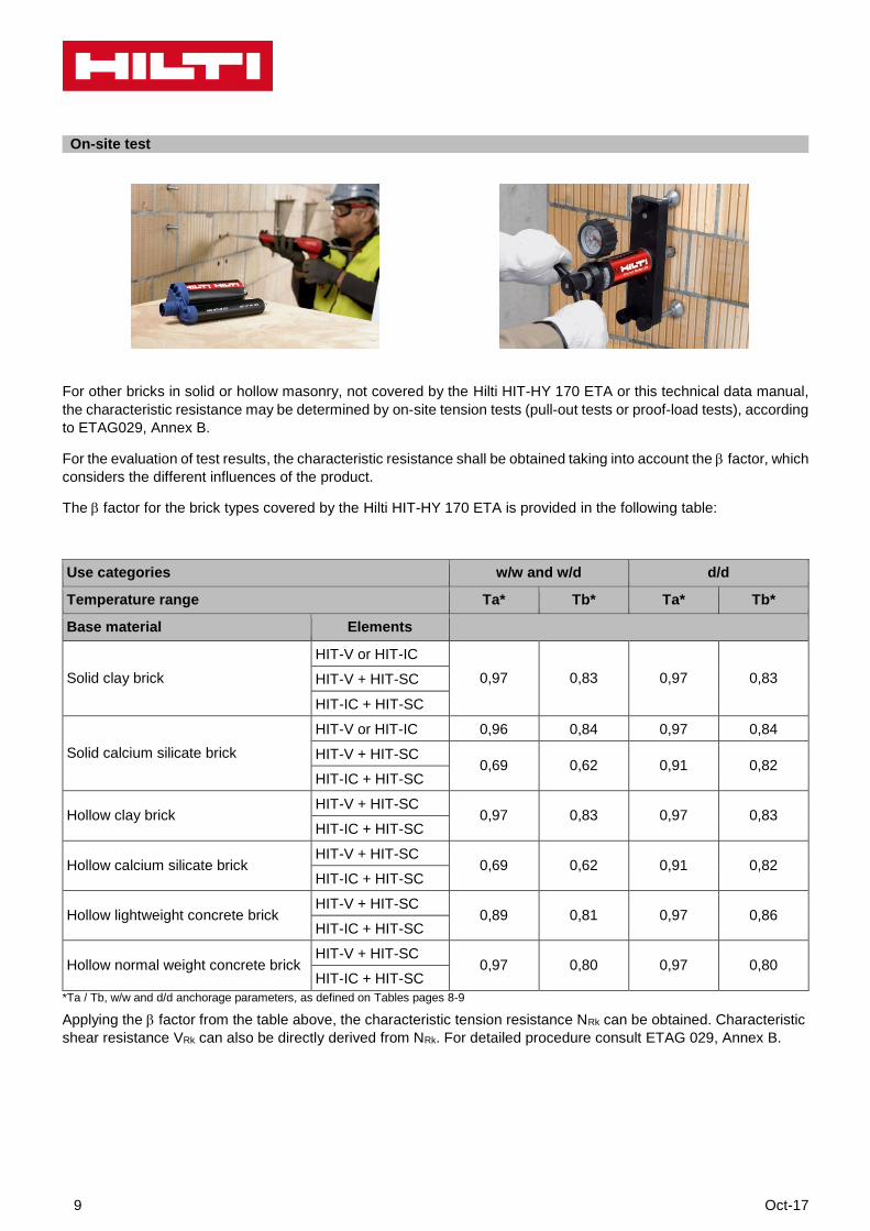
For other bricks in solid or hollow masonry, not covered by the Hilti HIT-HY 170 ETA or this technical data manual,
the characteristic resistance may be determined by on-site tension tests (pull-out tests or proof-load tests), according
to ETAG029, Annex B.
For the evaluation of test results, the characteristic resistance shall be obtained taking into account the factor, which
considers the different influences of the product.
The factor for the brick types covered by the Hilti HIT-HY 170 ETA is provided in the following table:
Use categories w/w and w/d d/d
Temperature range Ta* Tb* Ta* Tb*
Base material Elements
Solid clay brick
HIT-V or HIT-IC
0,97 0,83 0,97 0,83 HIT-V + HIT-SC
HIT-IC + HIT-SC
Solid calcium silicate brick
HIT-V or HIT-IC 0,96 0,84 0,97 0,84
HIT-V + HIT-SC 0,69 0,62 0,91 0,82
HIT-IC + HIT-SC
Hollow clay brick HIT-V + HIT-SC
0,97 0,83 0,97 0,83 HIT-IC + HIT-SC
Hollow calcium silicate brick HIT-V + HIT-SC
0,69 0,62 0,91 0,82 HIT-IC + HIT-SC
Hollow lightweight concrete brick HIT-V + HIT-SC
0,89 0,81 0,97 0,86 HIT-IC + HIT-SC
Hollow normal weight concrete brick HIT-V + HIT-SC
0,97 0,80 0,97 0,80 HIT-IC + HIT-SC
*Ta / Tb, w/w and d/d anchorage parameters, as defined on Tables pages 8-9
Applying the factor from the table above, the characteristic tension resistance NRk can be obtained. Characteristic
shear resistance VRk can also be directly derived from NRk. For detailed procedure consult ETAG 029, Annex B.
On-site test
Oct-17 10
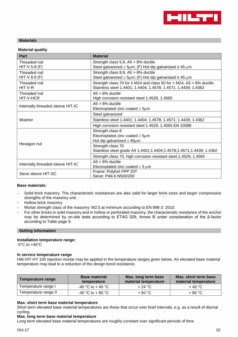
Materials Material quality
Part Material
Threaded rod HIT-V 5.8 (F)
Strength class 5.8, A5 > 8% ductile
Steel galvanized 5m; (F) Hot dip galvanized ≥ 45 m
Threaded rod HIT-V 8.8 (F)
Strength class 8.8, A5 > 8% ductile
Steel galvanized 5m; (F) Hot dip galvanized ≥ 45 m
Threaded rod HIT-V-R
Strength class 70 for ≤ M24 and class 50 for > M24, A5 > 8% ductile Stainless steel 1.4401; 1.4404; 1.4578; 1.4571; 1.4439; 1.4362
Threaded rod HIT-V-HCR
A5 > 8% ductile High corrosion resistant steel 1.4528, 1.4565
Internally threaded sleeve HIT-IC A5 > 8% ductile
Electroplated zinc coated 5m
Washer
Steel galvanized
Stainless steel 1.4401; 1.4404; 1.4578; 1.4571; 1.4439; 1.4362
High corrosion resistant steel 1.4529, 1.4565 EN 10088
Hexagon nut
Strength class 8
Electroplated zinc coated 5m
Hot dip galvanized 45m
Strength class 70 Stainless steel grade A4 1.4401;1.4404;1.4578;1.4571;1.4439; 1.4362
Strength class 70, high corrosion resistant steel,1.4529; 1.4565
Internally threaded sleeve HIT-IC A5 > 8% ductile
Electroplated zinc coated 5 m
Sieve sleeve HIT-SC Frame: Polyfort FPP 20T Sieve: PA6.6 N500/200
Base materials:
Solid brick masonry. The characteristic resistances are also valid for larger brick sizes and larger compressive strengths of the masonry unit.
Hollow brick masonry
Mortar strength class of the masonry: M2,5 at minimum according to EN 998-2: 2010.
For other bricks in solid masonry and in hollow or perforated masonry, the characteristic resistance of the anchor may be determined by on-site tests according to ETAG 029, Annex B under consideration of the β-factor according to Table page 9.
Setting information
Installation temperature range: -5°C to +40°C
In service temperature range Hilti HIT-HY 100 injection mortar may be applied in the temperature ranges given below. An elevated base material temperature may lead to a reduction of the design bond resistance.
Temperature range Base material temperature
Max. long term base material temperature
Max. short term base material temperature
Temperature range I -40 °C to + 40 °C + 24 °C + 40 °C
Temperature range II -40 °C to + 80 °C + 50 °C + 80 °C
Max. short term base material temperature Short term elevated base material temperatures are those that occur over brief intervals, e.g. as a result of diurnal cycling. Max. long term base material temperature Long term elevated base material temperatures are roughly constant over significant periods of time.
11 Oct-17
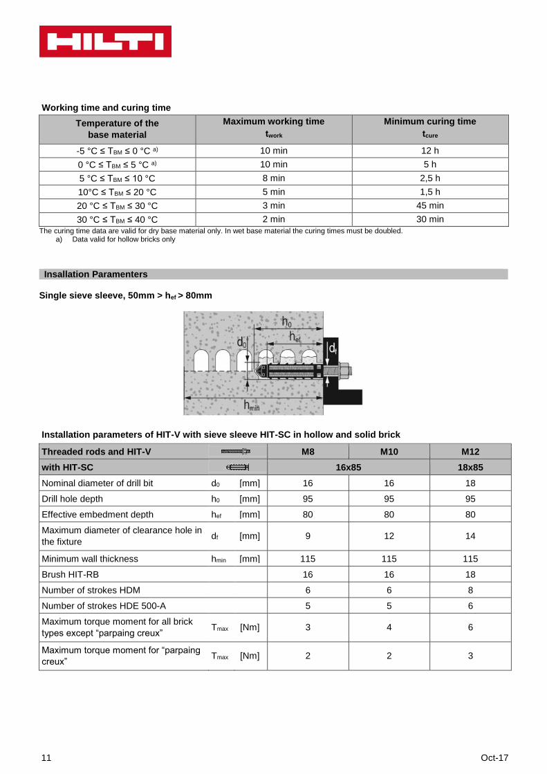
Working time and curing time
Temperature of the
base material
Maximum working time
twork
Minimum curing time
tcure
-5 °C ≤ TBM ≤ 0 °C a) 10 min 12 h
0 °C ≤ TBM ≤ 5 °C a) 10 min 5 h
5 °C ≤ TBM ≤ 10 °C 8 min 2,5 h
10°C ≤ TBM ≤ 20 °C 5 min 1,5 h
20 °C ≤ TBM ≤ 30 °C 3 min 45 min
30 °C ≤ TBM ≤ 40 °C 2 min 30 min
The curing time data are valid for dry base material only. In wet base material the curing times must be doubled. a) Data valid for hollow bricks only
Insallation Paramenters
Single sieve sleeve, 50mm > hef > 80mm
Installation parameters of HIT-V with sieve sleeve HIT-SC in hollow and solid brick
Threaded rods and HIT-V M8 M10 M12
with HIT-SC 16x85 18x85
Nominal diameter of drill bit d0 [mm] 16 16 18
Drill hole depth h0 [mm] 95 95 95
Effective embedment depth hef [mm] 80 80 80
Maximum diameter of clearance hole in
the fixture df [mm] 9 12 14
Minimum wall thickness hmin [mm] 115 115 115
Brush HIT-RB 16 16 18
Number of strokes HDM 6 6 8
Number of strokes HDE 500-A 5 5 6
Maximum torque moment for all brick
types except “parpaing creux” Tmax [Nm] 3 4 6
Maximum torque moment for “parpaing
creux” Tmax [Nm] 2 2 3
Oct-17 12
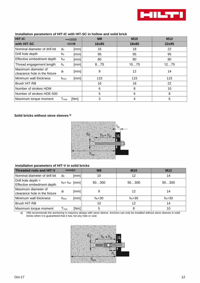
Installation parameters of HIT-IC with HIT-SC in hollow and solid brick
HIT-IC
M8 M10 M12
with HIT-SC
16x85 18x85 22x85
Nominal diameter of drill bit d0 [mm] 16 18 22
Drill hole depth h0 [mm] 95 95 95
Effective embedment depth hef [mm] 80 80 80
Thread engagement length hs [mm] 8…75 10…75 12…75
Maximum diameter of
clearance hole in the fixture df [mm] 9 12 14
Minimum wall thickness hmin [mm] 115 115 115
Brush HIT-RB 16 18 22
Number of strokes HDM 6 8 10
Number of strokes HDE-500 5 6 8
Maximum torque moment Tmax [Nm] 3 4 6
Solid bricks without sieve sleeves a)
Installation parameters of HIT-V in solid bricks
Threaded rods and HIT-V
M8 M10 M12
Nominal diameter of drill bit d0 [mm] 10 12 14
Drill hole depth =
Effective embedment depth h0= hef [mm] 50…300 50…300 50…300
Maximum diameter of
clearance hole in the fixture df [mm] 9 12 14
Minimum wall thickness hmin [mm] h0+30 h0+30 h0+30
Brush HIT-RB 10 12 14
Maximum torque moment Tmax [Nm] 5 8 10
a) Hilti recommends the anchoring in masonry always with sieve sleeve. Anchors can only be installed without sieve sleeves in solid bricks when it is guaranteed that it has not any hole or void.
13 Oct-17
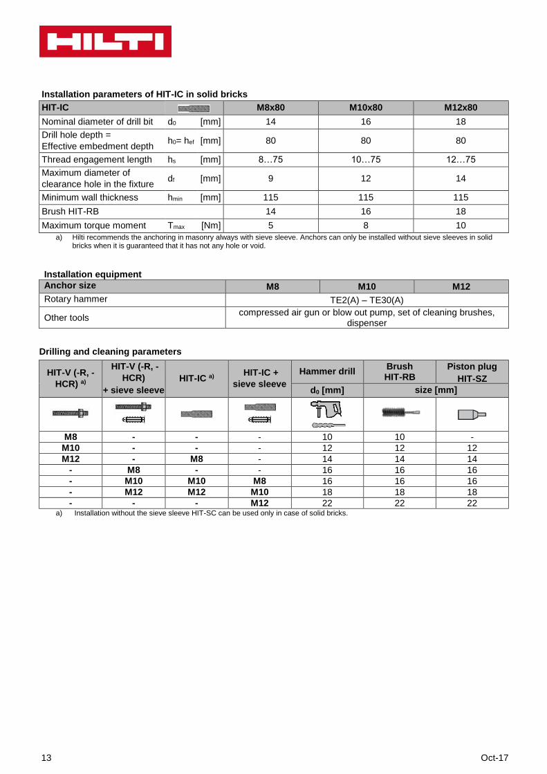
Installation parameters of HIT-IC in solid bricks
HIT-IC
M8x80 M10x80 M12x80
Nominal diameter of drill bit d0 [mm] 14 16 18
Drill hole depth =
Effective embedment depth h0= hef [mm] 80 80 80
Thread engagement length hs [mm] 8…75 10…75 12…75
Maximum diameter of
clearance hole in the fixture df [mm] 9 12 14
Minimum wall thickness hmin [mm] 115 115 115
Brush HIT-RB 14 16 18
Maximum torque moment Tmax [Nm] 5 8 10
a) Hilti recommends the anchoring in masonry always with sieve sleeve. Anchors can only be installed without sieve sleeves in solid bricks when it is guaranteed that it has not any hole or void.
Installation equipment
Anchor size M8 M10 M12
Rotary hammer TE2(A) – TE30(A)
Other tools compressed air gun or blow out pump, set of cleaning brushes,
dispenser
Drilling and cleaning parameters
HIT-V (-R, -
HCR) a)
HIT-V (-R, -
HCR)
+ sieve sleeve
HIT-IC a) HIT-IC +
sieve sleeve
Hammer drill Brush HIT-RB
Piston plug
HIT-SZ
d0 [mm] size [mm]
M8 - - - 10 10 -
M10 - - - 12 12 12
M12 - M8 - 14 14 14
- M8 - - 16 16 16
- M10 M10 M8 16 16 16
- M12 M12 M10 18 18 18
- - - M12 22 22 22 a) Installation without the sieve sleeve HIT-SC can be used only in case of solid bricks.
Oct-17 14
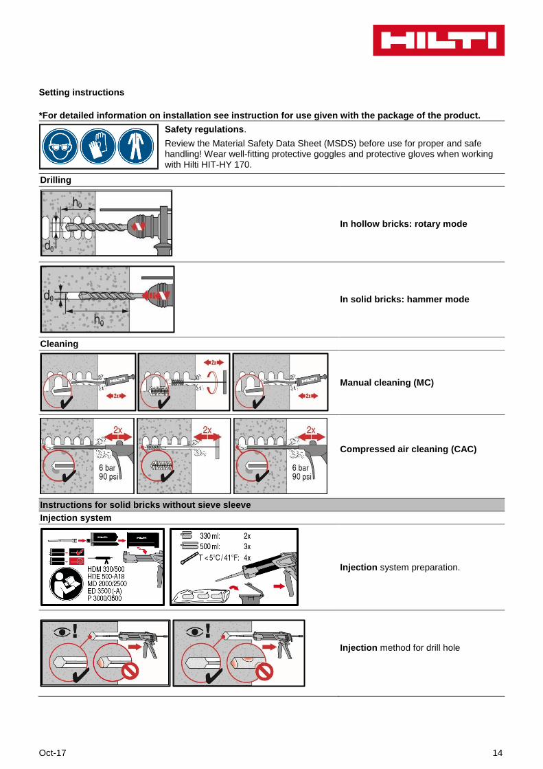
Setting instructions
*For detailed information on installation see instruction for use given with the package of the product.
Safety regulations.
Review the Material Safety Data Sheet (MSDS) before use for proper and safe handling! Wear well-fitting protective goggles and protective gloves when working with Hilti HIT-HY 170.
Drilling
In hollow bricks: rotary mode
In solid bricks: hammer mode
Cleaning
Manual cleaning (MC)
Compressed air cleaning (CAC)
Instructions for solid bricks without sieve sleeve
Injection system
Injection system preparation.
Injection method for drill hole
15 Oct-17
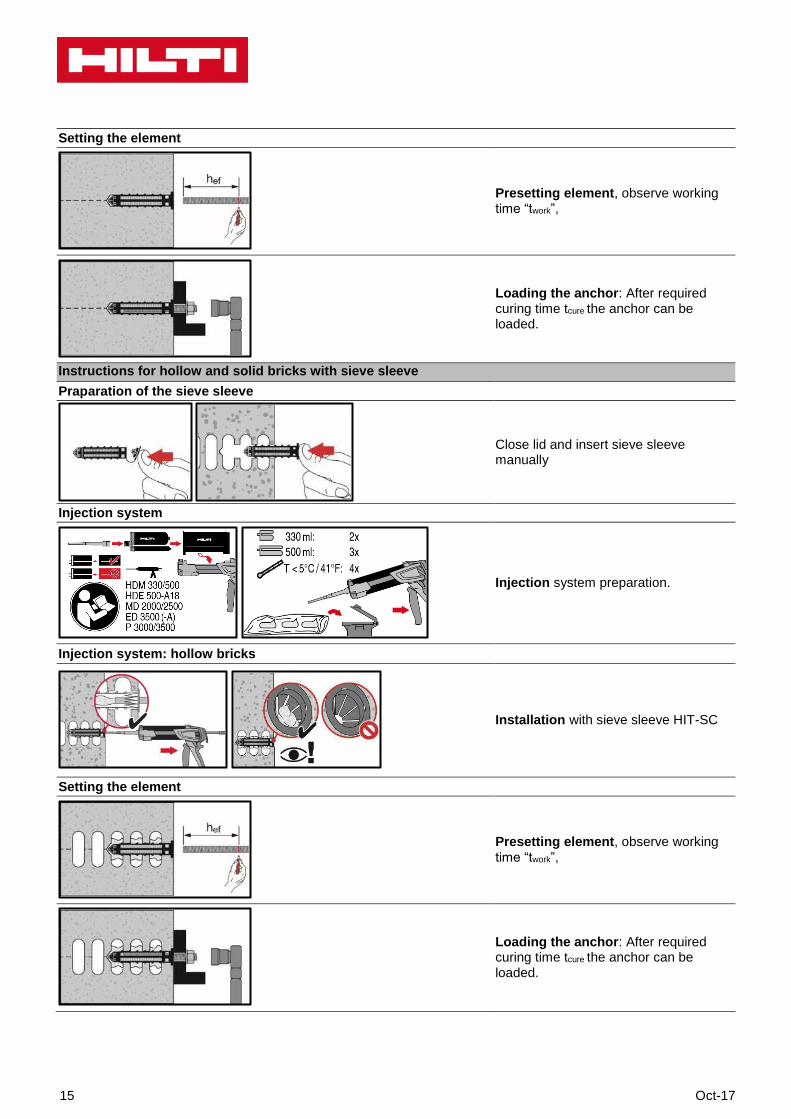
Setting the element
Presetting element, observe working time “twork”,
Loading the anchor: After required curing time tcure the anchor can be loaded.
Instructions for hollow and solid bricks with sieve sleeve Praparation of the sieve sleeve
Close lid and insert sieve sleeve manually
Injection system
Injection system preparation.
Injection system: hollow bricks
Installation with sieve sleeve HIT-SC
Setting the element
Presetting element, observe working
time “twork”,
Loading the anchor: After required curing time tcure the anchor can be loaded.
Oct-17 16