HIH9000 Series
13
Honeywell HumidIcon ™ Digital Humidity/Temperature Sensors HIH9000 Series • ±1.7 %RH Accuracy Datasheet
Transcript of HIH9000 Series
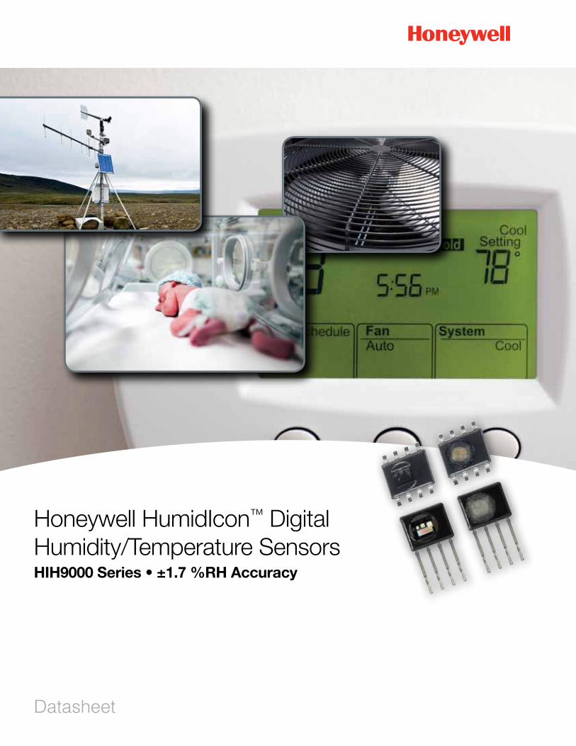
Honeywell HumidIcon™ Digital Humidity/Temperature Sensors HIH9000 Series • ±1.7 %RH Accuracy
Datasheet
2 sensing.honeywell.com
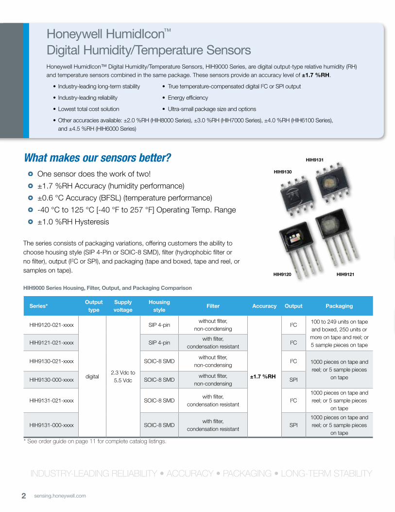
What makes our sensors better? • One sensor does the work of two!
• ±1.7 %RH Accuracy (humidity performance)
• ±0.6 °C Accuracy (BFSL) (temperature performance)
• -40 °C to 125 °C [-40 °F to 257 °F] Operating Temp. Range
• ±1.0 %RH Hysteresis
The series consists of packaging variations, offering customers the ability to choose housing style (SIP 4-Pin or SOIC-8 SMD), filter (hydrophobic filter or no filter), output (I2C or SPI), and packaging (tape and boxed, tape and reel, or samples on tape).
Honeywell HumidIcon™ Digital Humidity/Temperature Sensors Honeywell HumidIcon™ Digital Humidity/Temperature Sensors, HIH9000 Series, are digital output-type relative humidity (RH) and temperature sensors combined in the same package. These sensors provide an accuracy level of ±1.7 %RH.
• Industry-leadinglong-termstability • Truetemperature-compensateddigitalI2C or SPI output
• Industry-leadingreliability • Energyefficiency
•Lowesttotalcostsolution • Ultra-smallpackagesizeandoptions
•Otheraccuraciesavailable:±2.0%RH(HIH8000Series),±3.0%RH(HIH7000Series),±4.0%RH(HIH6100Series), and ±4.5 %RH (HIH6000 Series)
HIH9120 HIH9121
HIH9130
HIH9131
Series*Output
typeSupply voltage
Housing style
Filter Accuracy Output Packaging
HIH9120-021-xxxx
digital2.3Vdcto5.5Vdc
SIP 4-pinwithout filter,
non-condensing
±1.7 %RH
I2C 100 to 249 units on tape and boxed, 250 units or
more on tape and reel; or 5 sample pieces on tapeHIH9121-021-xxxx SIP 4-pin
with filter,condensation resistant
I2C
HIH9130-021-xxxx SOIC-8 SMDwithout filter,
non-condensingI2C 1000 pieces on tape and
reel; or 5 sample pieces on tapeHIH9130-000-xxxx SOIC-8 SMD
without filter,non-condensing
SPI
HIH9131-021-xxxx SOIC-8 SMDwith filter,
condensation resistantI2C
1000 pieces on tape and reel; or 5 sample pieces
on tape
HIH9131-000-xxxx SOIC-8 SMDwith filter,
condensation resistantSPI
1000 pieces on tape and reel; or 5 sample pieces
on tape
* See order guide on page 11 for complete catalog listings.
HIH9000 Series Housing, Filter, Output, and Packaging Comparison
INDUSTRY-LEADING RELIAbILITY • ACCURACY • pACkAGING • LoNG-TERm STAbILITY

3sensing.honeywell.com
±1.7ACC
URACY%RH
Features and Benefits
*Competitive Differentiator
InduStRy-leAdIng lOng-teRm StAbIlIty* (1.2 %RH OveR FIve yeARS)Competitive humidity sensors require a 12 hour at 75 %RH rehydration process (which requires special equipment chambers) to correct reflow temperature offset. Honeywell’s sensor also experiences an offset after reflow; however, it only requires a five-hour rehydration under ambient conditions (>50 %RH). Honeywell’sindustry-leadinglong-termstability:
•Minimizessystemperformanceissues
•Helpssupport system uptime by eliminating the need to service or replace the sensor during its application life
•eliminates the need to regularly recalibrate the sensor in the application, which can be inconvenient and costly
InduStRy-leAdIng RelIAbIlIty (mttF 9,312,507 HR)*Thermoset-polymer capacitive sensing element’s multilayer construction provides resistance to most application hazards such as condensation, dust, dirt, oils, and common environmental chemicals, which help provide industry-leading reliability
lOweSt tOtAl COSt SOlutIOn*Honeywell’s HumidIcon HIH9000 Series delivers the lowest total cost solution due to the sensor’s industry-leading combined humidity/temperature sensor
COmbIned HumIdIty And temPeRAtuRe SenSORAllows the RH measurement to be temperature compensated, and provides a second, standalone temperature sensor output; allows the user to purchase one sensor instead of two
eneRgy eFFICIent*• Low supply voltage: Canoperatedownto2.3Vdc,whichallowsuseinlow
energy and wireless-compatible applications to enhance energy savings and prolong system battery life
• Low power consumption: The sensor goes into sleep mode when not taking a measurement within the application, consuming only 1 µA of power versus 750 µA in full operation in a battery operated system; sleep mode helps maximizebatterylife,reducespowersupplysize,andreducestheapplication’soverall weight
Offers customers the lowest total cost solution.
One sensor does the work of two!

4 sensing.honeywell.com
HIgH ReSOlutIOnHigh 14-bit humidity sensor resolution and 14-bit temperature sensor resolution within the application help the user’s system detect the smallest relative humidity or temperature change
tRue, temPeRAtuRe-COmPenSAted dIgItAl I2C OR SPI OutPut*Typically allows the customer to remove the components associated with signal conditioning from the PCB to free up space and reduce costs associated with those components (e.g., acquisition, inventory, assembly). True, temperature-compensated digital I2C or SPI output often eliminates problems that could occur from having multiple signal conditioning components across the PCB, as well as simplifies integration to the microprocessor, eliminating the need for customer-implemented, complex signal conditioning
HOuSIng StyleSOIC-8SMD(SurfaceMountDevice)orSIP4Pin;ultra-smallsizeallowsforflexibility of use within the application, occupies less space on the PCB, and typically simplifies placement on crowded PCBs or in small devices; industry standard design simplifies design-in
FIlteRAvailable with hydrophobic filter and condensation-resistance, allowing for use in many condensing environments, or without hydrophobic filter, non-condensing
tAPe And ReelAllows for use in high volume, automated pick-and-place manufacturing, eliminating lead misalignment to the PCB and helping the customer to reduce manufacturing costs
wIde OPeRAtIng temPeRAtuRe RAnge-40 °C to 125 °C [-40 °F to 257 °F] allows for use in many applications
OPtIOnAl One OR twO %RH level AlARm OutPutSProvides the ability to monitor whether the RH level has exceeded or fallen below predetermined and critical levels within the application
multI-FunCtIOn ASICDelivers flexibility within the application by lowering or eliminating the risk and cost ofOEMcalibration
ROHS And weee COmPlIAnt, HAlOgen FRee
Free up PCB space. Reduce costs.
Choose options to best fit the application.
Features and Benefits
*Competitive Differentiator

5sensing.honeywell.com
InduStRIAl
HvAC/R
May be used to provide precise RH and temperature measurement in air conditioning/air movement systems, enthalpy sensing, thermostats, humidifiers/dehumidifiers, and humidistats to maintain occupant comfort and ideal storage humidity/temperature while achieving low energy consumption, supporting system accuracyandwarrantyrequirements,maximizingsystemuptime,andimprovingoverall system quality.
AIR COmPReSSORS
May be used to provide precise RH measurement in compressed air lines, allowing the system to remove any condensation; dry compressed air is critical for customer process control measurement.
weAtHeR StAtIOnS
May be used to provide precise RH and temperature measurement in ground-based and airborne weather stations, allowing real time and highly accurate monitoring/reporting of actual weather conditions.
teleCOm CAbInetS
May be used to provide precise RH and temperature measurement in the telecom cabinetHVACsystem;maintainingpropertemperatureandhumiditylevelsinthecabinet provides maximum system uptime and performance.
InduStRIAl InCubAtORS/mICROenvIROnmentS
May be used to provide optimal temperature and RH levels to support critical processes and experiments, enhancing process efficiency with desired climate conditions.
medICAl
ReSPIRAtORy tHeRAPy
May be used to provide precise RH and temperature measurement in sleep apnea machines and ventilators, enhancing patient comfort, safety and treatment effectiveness with warm and humidified air.
InCubAtORS/mICROenvIROnmentS
May be used to provide optimal temperature and RH levels to support critical processes and experiments, enhancing process efficiency with desired climate conditions.
Potential Applications

6 sensing.honeywell.com
HIH9000 Series • ±1.7 %RH Accuracy
table 1. environmental Specifications
Characteristic Condition min. typ. max. unit
Operating temperature range powered -40 [-40] – 125 [257] °C [°F]
Operating humidity range powered 0 – 100 %RH
Storage temperature range unpowered -40 [-40] – 125 [257] °C [°F]
Storage humidity range – 30 – 50 %RH
Solderingtemperature:manualautomated
4 s reflow peak30sreflowpeak
––
––
350[662]260 [500]
°C [°F]
ESD MIL-STD883H,Method3015.7 – – ±4 kV
Latch-up immunity – – – ±100 m
ShockMIL-STD202G,Method213D,TestConditionC,half-sine,6ms±3perpendicularaxis,3shock
pulses per axis– – 100 g
VibrationMIL-STD 202G, Method 204D, Test Condition D,
10Hzto2000Hz– – 20 g
Light sensitivity exposed to 50 lumens yellow light; exhibited no change in output
Reliability (MTTF) 9,312,507hr
table 2. Humidity Performance Specifications
Characteristic Condition min. typ. max. unit
Supply voltage variation effect on humidity
2.3Vdcto5.5Vdc – 0.1 1.5 %RH/V
Compensated humidity range1 5 °C to 50 °C [41 °F to 122 °F] 10 – 90 %RH
Compensated temp. range1 – 5 [41] – 50 [122] °C [°F]
Resolution 14 bit ADC resolution – – 0.04 %RH
Accuracy2 25 °C [77 °F] rising RH – ±1.7 – %RH
Maximal accuracy – – ±3.0 – %RH
Hysteresis – – ±1.0 – %RH
Total error band35 °C to 50 °C [41 °F to 122 °F],
20 %RH to 80 %RH– ±5.0 – %RH
Long term stability 50 %RH, 25 °C [77 °F], 5 years – ±0.05 ±1.2 %RH
Response time t63% – – 8 s
Impact of solderingIPC/EIA/JEDECJ-STD-020D,peaktemp.
of 260 °C [500 °F]– – ±2.5 %RH
notes:1ConversionFormulas:
14bitADCoutputforhumidityto%RH: 14bitADCoutputfortemperatureconversionto°C:
Humidity (%RH) = Humidity_14_bit_ADC_output x 100 214 – 2
Temperature (C°) = Temperature_14_bit_ADC_output x 165 – 40 214 – 2
2 Accuracyisspecifiedatthetypicalsupplyvoltageof3.3Vdcandat25°C[77°F].Itisthemaximumdeviationfromtheidealtransferfunctionofrelative humidity measured over the compensated humidity range of 10 %RH to 90 %RH.
3 Total error band is the maximum deviation from the ideal transfer function of relative humidity over the compensated range of 5 °C [41 °F] to 50 °C [122°F].Itincludesallerrorsduetohumiditynon-linearity,humidityhysteresis,humiditynon-repeatability,thermaleffectonzero,thermaleffectonspan and thermal hysteresis.

7sensing.honeywell.com
Honeywell HumidIcon™ Digital Humidity/Temperature Sensors
Table 3. temperature Performance Specifications
Characteristic Condition min. typ. max. unit
Supply voltage variation effect on temperature
2.3Vdcto5.5Vdc – 0.1 1.0 °C/V
Compensated temp. range – 5 [41] – 50 [122] °C [°F]
Resolution 14 bit ADC resolution – – 0.025 °C
Accuracy (BFSL)1 5 °C to 50 °C [41 °F to 122 °F] – ±0.6 – °C
Long term stability 25 °C for 5 years – – ±0.05 °C/yr
Response time t63% – – 30 s
Impact of solderingIPC/EIA/JEDECJ-STD-020D,peaktemp.
of 260 °C [500 °F]– – ±0.1 °C
note:1 Accuracy is specified over the compensated temperature range.
table 4. Current Consumption
Characteristic vDD Abbr. Condition typ. max. unit
Sleep current 3.3 ISLEEP – 0.6 1 µA
Supplycurrent: I2C SPI
3.33.3
IDD
IDD
14 bit fastest update, no sleep14 bit fastest update, no sleep
0.650.75
11
mAmA
table 5. Input and Output Characteristics
Characteristic Abbr. Condition min. typ. max. unit
Supply voltage VDD – 2.3 3.3 5.5 Vdc
Low level output voltage VOL IOL = 2.8 mA min. – – 20 % VDD
High level output voltage VOH IOH = -2.8 mA min. 80 % – – VDD
Low level input voltage VIL – – – 20 % VDD
High level input voltage VIH – 80 % – – VDD
Pull-upresistor: I2C SPI (for SS only)
RP
RSS
––
––
2.210
––
kOhmkOhm
table 6. measurement timing
Characteristic Abbr. Condition min. typ. max. unit
Start-up time (power-on to data ready)
TSTA 14 bit TH and 14 bit humidity resolution – 50 60 ms
Updaterate applicationdependent:measurementsaretakenonlywhentheapplicationrequeststhem

8 sensing.honeywell.com
Figure 1. I2C timing diagram
SDA
SCL
tLOW
tHDSTA
tHDSTA
tHIGHtHDDAT tSUSTA tSUSTO
tBUStSUDAT
Characteristic Abbr. min. typ. max. unit
SCL clock frequency FSCL 100 – 400 kHz
Start condition hold time relative to SCL edge tHDSTA 0.1 – – µs
Minimum SCL clock low width1 tLOW 0.6 – – µs
Minimum SCL clock high width1 tHIGH 0.6 – – µs
Start condition setup time relative to SCL edge tSUSTA 0.1 – – µs
Data hold time on SDA relative to SCL edge tHDDAT 0 – 0.5 µs
Data setup time on SDA relative to SCL edge tSUDAT 0.1 – – µs
Stop condition setup time on SCL tSUSTO 0.1 – – µs
Bus free time between stop and start condition tBUS 1 – – µs
note:1 Combined low and high widths must equal or exceed minimum SCL period.
Figure 2. SPI timing diagram
tBUS
tCLKD
SCLK
MISO
SS
tHIGH
tSUSS
HiZHiZ
tHDSS tLOW
tCLKD
Characteristic Abbr. min. typ. max. unit
SCLK clock frequency fSCL 50 – 800 kHz
SS drop to first clock edge tHDSS 2.5 – – μs
Minimum SCLK clock low width1 tLOW 0.6 – – μs
Minimum SCLK clock high width1 tHIGH 0.6 – – μs
Clock edge to data transition tCLKD 0 – 0.5 μs
Rise of SS relative to last clock edge tSUSS 0.1 – – μs
Bus free time between rise and fall of SS tBUS 2 – – µs
note:1 Combined low and high widths must equal or exceed minimum SCLK period.
HIH9000 Series • ±1.7 %RH Accuracy

9sensing.honeywell.com
Honeywell HumidIcon™ Digital Humidity/Temperature Sensors
Figure 3. SOIC-8 Smd typical Application Circuits
I2C SPI
Digital Humidity/Temp. Sensor
VDD
VCORE
VSS
NC
SCL
SDA
AL_L
AL_H
VSUPPLY = 2.3 Vdc to 5.5 Vdc
GND
GND
12 V
0.1 µF
0.22 µF
2.2 kOhm
8 3
4
5
6
1
2
7
LED
2.2 kOhm Digital Humidity/Temp.
Sensor
VDD
VCORE
VSS
NC
SS
SCLK
MISO
AL_LGND
0.1 µF
0.22 µF
10 kOhm
8 3
4
6
5
1
2
7
LED
VSUPPLY = 2.3 Vdc to 5.5 Vdc
Figure 4. SOIC-8 Smd mounting dimensions, PCb landing Pattern and Pinout [For reference only: mm/[in].)
mounting landing Pattern
4,90[0.193]
3,90[0.153]
1,905[0.075]
1,27[0.050]
0.41[0.016]
1 2 3 4
8 7 6 5
6,0[0.236]
0,15[0.006]
0,203[0.0080]
2,055[0.081]
8X 0,61 [0.024]
8X 2,03 [0.08]
4X 4,9 [0.193]
6X 1,27 [0.05]
Pinout for I2C versions Pinout for SPI versions
Pin ASIC Pad description Pin ASIC Pad description
1 VCORE connect via 0.1 µF to ground 1 VCORE connect via 0.1 µF to ground
2 VSS supply ground 2 VSS supply ground
3 SCL I2C clock 3 SS slave select (Input)
4 SDA I2C data 4 SCLK serial clock
51 AL_H alarm output high 5 MISO master-in-slave-out
61 AL_L alarm output low 61 AL_L alarm output low
7 NC not connected externally 7 NC not connected externally
8 VDD supply voltage, connect via 0.22 µF to ground 8 VDD supply voltage, connect via 0.22 µF to ground1 Do not connect Pin(s) 5 and/or 6 if the built-in alarm feature is not desired. 1 Do not connect Pin 6 if the built-in alarm feature is not desired.
tape and Reel
4,00[0.157]
1,50 [0.059]
1,75[0.069]
0,32[0.013]
13[0.51]
330[13,0]
21,4[0.84]
102[4.0]
8,00[0.315]
16,00[0.630]
5,00[0.197]
2,61[0.103]
10 sensing.honeywell.com
HIH9000 Series • ±1.7 %RH Accuracy
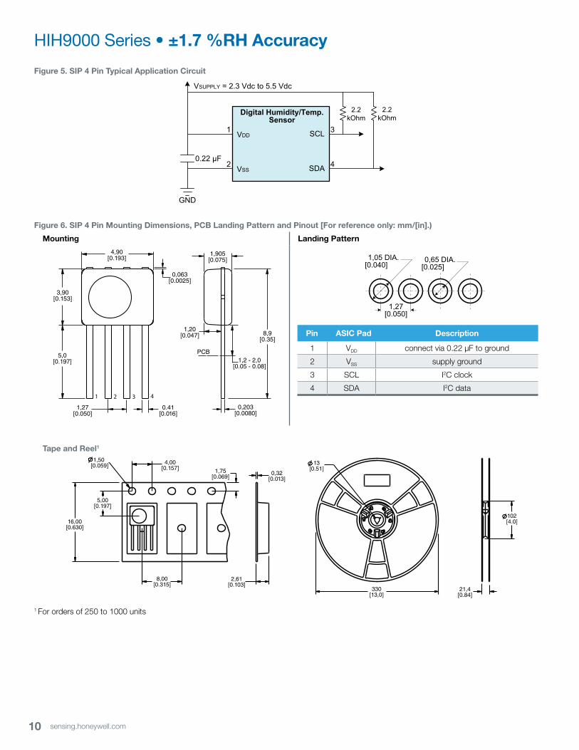
Figure 5. SIP 4 Pin typical Application Circuit
Digital Humidity/Temp. Sensor
VDD
VSS
SCL
SDA
VSUPPLY = 2.3 Vdc to 5.5 Vdc
GND
0.22 µF
2.2 kOhm
1 3
42
2.2 kOhm
Figure 6. SIP 4 Pin mounting dimensions, PCb landing Pattern and Pinout [For reference only: mm/[in].)
mounting landing Pattern
1 2 3 4
8,9[0.35]
1,20[0.047]
PCB1,2 - 2,0
[0.05 - 0.08]
4,90[0.193]
3,90[0.153]
5,0[0.197]
1,27[0.050]
0.41[0.016]
0,063[0.0025]
0,203[0.0080]
1,905[0.075]
1,27[0.050]
1,05 DIA.[0.040]
0,65 DIA.[0.025]
tape and Reel1
4,00[0.157]
1,50 [0.059]
1,75[0.069]
0,32[0.013]
13[0.51]
330[13,0]
21,4[0.84]
102[4.0]
8,00[0.315]
16,00[0.630]
5,00[0.197]
2,61[0.103]
1 For orders of 250 to 1000 units
Pin ASIC Pad description
1 VDD connect via 0.22 µF to ground
2 VSS supply ground
3 SCL I2C clock
4 SDA I2C data

11sensing.honeywell.com
Honeywell HumidIcon™ Digital Humidity/Temperature Sensors
Order guide
Catalog listing description
HIH9120-021-0011HoneywellHumidIcon™DigitalHumidity/TemperatureSensors:HIH9000Series,I2C, ±1.7 %RH accuracy, SIP 4 Pin, without filter, non-condensing, 100 units on tape
HIH9120-021-001SHoneywellHumidIcon™DigitalHumidity/TemperatureSensors:HIH9000Series,I2C, ±1.7 %RH accuracy, SIP 4 Pin, without filter, non-condensing, five units on tape (sample)
HIH9121-021-0011HoneywellHumidIcon™DigitalHumidity/TemperatureSensors:HIH9000Series,I2C, ±1.7 %RH accuracy, SIP 4 Pin, with filter, condensation-resistant, 100 units on tape
HIH9121-021-001SHoneywellHumidIcon™DigitalHumidity/TemperatureSensors:HIH9000Series,I2C, ±1.7 %RH accuracy, SIP 4 Pin, with filter, condensation-resistant, five units on tape (sample)
HIH9130-000-001HoneywellHumidIcon™DigitalHumidity/TemperatureSensors:HIH9000Series,SPI,±1.7%RHaccuracy,SOIC-8 SMD, without filter, non-condensing, 1000 units on tape and reel
HIH9130-000-001SHoneywellHumidIcon™DigitalHumidity/TemperatureSensors:HIH9000Series,SPI,±1.7%RHaccuracySOIC-8 SMD, without filter, non-condensing, five units on tape (sample)
HIH9130-021-001HoneywellHumidIcon™DigitalHumidity/TemperatureSensors:HIH9000Series,I2C, ±1.7 %RH accuracy, SOIC-8 SMD, without filter, non-condensing, 1000 units on tape and reel
HIH9130-021-001SHoneywellHumidIcon™DigitalHumidity/TemperatureSensors:HIH9000Series,I2C, ±1.7 %RH accuracy, SOIC-8 SMD, without filter, non-condensing, five units on tape (sample)
HIH9131-000-001HoneywellHumidIcon™DigitalHumidity/TemperatureSensors:HIH9000Series,SPI,±1.7%RHaccuracy,SOIC-8 SMD, with filter, condensation-resistant, 1000 units on tape and reel
HIH9131-000-001SHoneywellHumidIcon™DigitalHumidity/TemperatureSensors:HIH9000Series,SPI,±1.7%RHaccuracy,SOIC-8 SMD, with filter, condensation-resistant, five units on tape (sample)
HIH9131-021-001HoneywellHumidIcon™DigitalHumidity/TemperatureSensors:HIH9000Series,I2C, ±1.7 %RH accuracy, SOIC-8 SMD, with filter, condensation-resistant, 1000 units on tape and reel
HIH9131-021-001SHoneywellHumidIcon™DigitalHumidity/TemperatureSensors:HIH9000Series,I2C, ±1.7 %RH accuracy, SOIC-8 SMD, with filter, condensation-resistant, five units on tape (sample)
1 Orders of 250 units or more are packaged on tape and reel.

12 sensing.honeywell.com
SENSOR REHYDRATION
nOtICe: SenSOR ReHydRAtIOn
• Exposuretoelevatedtemperatures,suchasthoseexperienced during solder reflow, may dry out the sensing element. It is recommended that the sensor be allowed time to rehydrate after soldering or other high temperature/dry exposures.
• Exposuretotheseconditionswillnotpermanentlydamagethesensor. It will generally return to its factory-calibrated value after rehydration.
• Ifrehydrationisnotperformed,thesensormayreadaslightoffset that slowly disappears over time as the sensor becomes exposed to ambient conditions. Conversely, extended exposure to condensing and high humidity environments (>90 %RH) may cause a revisable shift in readings which will generally return to normal after the sensor has been allowed to dry off.
To rehydrate the sensor, expose it to room temperature under ambient conditions (>50 %RH) for a minimum of five hours.
AddItIOnAl InFORmAtIOnThefollowingassociatedliteratureisavailableontheWeb:• Productinstallationinstructions
• Productapplicationnote
• Applicationsheets:
– Humidity Sensor Performance Characteristics
– Humidity Sensor Theory and Behavior
– Humidity Sensor Moisture and Psychrometrics
– Humidity Sensor Chemical Resistivity
– Thermoset Polymer-Based Capacitive Sensors
• TechnicalNotes:
– I2C Communication with the Honeywell HumidIcon™ Digital Humidity/Temperature Sensors
– SPI Communication with the Honeywell HumidIcon™ Digital Humidity/Temperature Sensors
– UsingAlarmsontheHoneywellHumidIcon™DigitalHumidity/Temperature Sensors
– EnteringandUsingCommandModeontheHoneywellHumidIcon™ Digital Humidity/Temperature Sensors
WARNINGPERSONAL INJURYDO NOT USE these products as safety or emergency stop devices or in any other application where failure of the product could result in personal injury.
Failure to comply with these instructions could result in death or serious injury.
WARNINGMISUSE OF DOCUMENTATION• Theinformationpresentedinthisproductsheetisfor
reference only. Do not use this document as a product installation guide.
• Completeinstallation,operation,andmaintenanceinformation is provided in the instructions supplied with each product.
Failure to comply with these instructions could result in death or serious injury.
HIH9000 Series • ±1.7 %RH Accuracy
wARRAnty/RemedyHoneywell warrants goods of its manufacture as being free of defective materials and faulty workmanship. Honeywell’s standard product warranty applies unless agreed to otherwise by Honeywell in writing; please refer to your order acknowledgement or consult your local sales office for specific warranty details. If warranted goods are returned to Honeywell during the period of coverage, Honeywell will repair or replace, at its option, without charge those items it finds defective. the foregoing is buyer’s sole remedy and is in lieu of all other warranties, expressed or implied, including those of merchantability and fitness for a particu-lar purpose. In no event shall Honeywell be liable for conse-quential, special, or indirect damages.
While we provide application assistance personally, through our literature and the Honeywell website, it is up to the customer to determine the suitability of the product in the application.
Specifications may change without notice. The information we supply is believed to be accurate and reliable as of this printing. However, we assume no responsibility for its use.

009076-3-EN IL50 GLO July 2013Copyright © 2013 Honeywell International Inc. All rights reserved.
Sensing and Control
Honeywell
1985 Douglas Drive North
Golden Valley, MN 55422
www.honeywell.com
Find out moreHoneywell serves its customers through a worldwide network of sales offices, representatives and distributors. For application assistance, current specifications, pricing or name of the nearest Authorized Distributor, contact your local sales office.
To learn more about Honeywell’s
sensing and control products,
call +1-815-235-6847 or
1-800-537-6945, visit
sensing.honeywell.com, or e-
mail inquiries to