
HIGHWAY STANDARDS DEVELOPMENT PROCEDURES … · HIGHWAY STANDARDS & DEVELOPMENT PROCEDURES for the...
142
HIGHWAY STANDARDS & DEVELOPMENT PROCEDURES for the ASSOCIATION of CANYON COUNTY HIGHWAY DISTRICTS May 2007
Transcript of HIGHWAY STANDARDS DEVELOPMENT PROCEDURES … · HIGHWAY STANDARDS & DEVELOPMENT PROCEDURES for the...

HIGHWAY STANDARDS&
DEVELOPMENT PROCEDURESfor the
ASSOCIATION ofCANYON COUNTY HIGHWAY DISTRICTS
May 2007
cmeyer
Typewritten Text
January 2010 Revision
cmeyer
Typewritten Text
cmeyer
Typewritten Text
cmeyer
Typewritten Text

JANUARY 2010
UPDATE TO THE
HIGHWAY STANDARDS
AND
DEVELOPMENT PROCEDURES
FOR THE
ASSOCIATION OF CANYON COUNTY HIGHWAY DISTRICTS (ACCHD)
(December 2008 Edition)
The following Sections of the Highway Standards and Development Procedures for the Association of Canyon
County Highway Districts (ACCHD), December 2008 Edition are amended by this January 2010 Update. Italic bold
font has been used to identify the January, 2010 revisions. This update requires the replacement of the following
pages (identifiable by the footer date – January 2010):
This Table identifies the revised sections and pages for the January 2010 revision.
Section 2000 Section 3000 Section 4000 Section 5000 Appendix/Std Dwg 2040.010 (Pg 2000-13)
3030.010 (Pg 3000-3 thru 4)
SD-303, note 1 (Pg 4000-5)
5070.010 (Pg 5000-4)
ACCHD-101A
2130.040 (Pg 2000-21)
3040.060 (Pg 3000-6)
810.3.14.B.2 (Pg 4000-15 thru 17)
5070.020 (Pg 5000-5)
ACCHD-102
3080.010 (pg 3000-23)
2060, Guardrail, Part 4 (pg 4000-23)
5070.060 (pg 5000-7)
ACCHD-102A
3090.010 (pg 3000-24)
3300 (pg 3000-29)


Highway Standards and Development Procedures
for the Association of Canyon County Highway Districts
MANUAL UPDATE REQUEST FORM
Although significant effort has been put forth in the preparation of the Highway Standards and Development
Procedures for the Canyon County Highway Districts, not all conditions of development, site characteristics or
unusual circumstances can be addressed within this manual. Therefore, this form is included to provide an
avenue for Manual users to request updates, revisions or corrections. To request a revision to this manual,
submit this completed form to the District for their consideration. Periodically the Association of Canyon
County Highway Districts (ACCHD) will review the revision requests and if appropriate, Manual Updates will be
prepared. Date:
Revision Requested by:
Manual Section Number of Revision Request:
Manual Page Number of Revision request:
Revision Request:
Reason / Justification for Revision:

FORWARD
The four Districts within Canyon County, Idaho are members of the Multi-Jurisdiction Transportation
Committee, known as the Association of Canyon County Highway Districts (ACCHD) and continual
communication and joint use of special equipment occurs between all four of the Districts.
The ACCHD has promulgated these Standards and Procedures for the construction by developers of public
roads within the Districts’ respective boundaries. A public road constructed by a developer in accordance with
these Standards and Procedures may be included in the District road system and will be eligible for permanent
maintenance and repair.
Variance to these Standards may be allowed where extraordinary circumstances exist by reason of terrain,
safety, or other site characteristics. Each variance will be determined on its own merits by the District having
jurisdiction over the road.
ACCHD has adopted the Idaho Standards for Public Works Construction (ISPWC), latest edition, as its basic
construction standard as modified in Section 4000. Copies of that document may be purchased from the Local
Highway Technical Assistance Council (LHTAC). The Highway Standards and Development Procedures
contained herein are to be used in conjunction with the ISPWC. In the event of conflict, the ACCHD Manual
shall take precedence.
The Highway Standards and Development Procedures for the ACCHD have been updated with the assistance of
PARAGON Consulting, Inc.
This Manual update has been completed as part of the Districts’ ongoing effort to apply best transportation
standards and practices. The recent significant increase of development within rural Canyon County has been
taxing the ACCHD Districts’ ability to maintain the existing roadway network and provide the needed capacity
improvements required to support the rapidly increasing traffic volumes throughout Canyon County.
Additionally, ACCHD is updating these standards so the Districts’ standards are more consistent with the
adjacent jurisdictions namely, Ada County Highway District, City of Nampa, City of Caldwell and City of
Middleton.

Some of the major revisions to the ACCHD Standards include:
Clarification of the subdivision and development process of the Districts, especially in areas of city
impact.
More descriptive submittal requirements at all stages of a development.
Modification of road and driveway access control policy to provide more stringent control on arterial
and major collector roadways.
Modifications of right-of-way requirements requiring increased right-of-way on arterial and collector
roads.
Clarification of acceptable hydrologic and hydraulic calculation methodology.
Modification of the requirements for traffic studies.
Modification of the required minimum thickness for roadway sections including an increase in the
thickness for arterial and collector roads.
Addition of the requirement for developers to complete frontage roadway improvements along the
development.
Revisions of the construction specifications to more closely follow the Idaho Standards for Public
Works Construction (ISPWC).
All Developers and Engineers developing and designing projects requiring approval of the District are
required to maintain a copy of these standards, as well as the most current Idaho Standards for Public
Works Construction (ISPWC). The ACCHD standards are available from the District and the ISPWC is
available from the Local Highway Technical Assistance Council at (208) 344-0565.

HIGHWAY DISTRICT INFORMATION
Nampa Highway District No. 1 Notus-Parma Highway District No. 2 4507 Highway 45 106 South 4th Street P.O. Box 76 P.O. Box 719 Nampa, ID 83653 Parma, ID 83660 Phone (208) 467-6576 Phone: (208) 722-5343 Fax: (208) 467-9916 Fax: (208) 722-5896 Golden Gate Highway District No. 3 Canyon Highway District No. 4 500 Golden Gate Avenue 15435 Highway 44 P.O. Box 38 Caldwell, ID 83607 Wilder, ID 83676 Phone: (208) 454-8135 Phone: (208) 482-6267 Fax: (208) 454-2008 Fax: (208) 482-6100

TABLE OF CONTENTS
SECTION 1000 – INTRODUCTION ...................................................................................... 1000-1 1010. Authority of Highway Districts ....................................................................... 1000-1 1020. Need for Control and Uniformity .................................................................... 1000-1 SECTION 2000 – GENERAL PROCEDURES AND CONDITIONS ........................................................ 2000-1 2010. Subdivision and Development Process .............................................................. 2000-1 2020. Right-of-Way Dedication .............................................................................. 2000-4 2030. Application Requirements and Content ............................................................ 2000-6 2040. Coordination with Utilities and the District ..................................................... 2000-12 2050. Financial Guarantee Agreements ................................................................. 2000-13 2060. Construction .......................................................................................... 2000-13 2070. Construction Observation .......................................................................... 2000-14 2080. Fees for Plan Review and Construction Observation ........................................... 2000-14 2090. Testing ................................................................................................ 2000-15 2100. Area of City Impact .................................................................................. 2000-15 2110. Acceptance into District System .................................................................. 2000-16 2120. Special Permits ....................................................................................... 2000-16 2130. Road Names and Signs .............................................................................. 2000-21 2140. Variances .............................................................................................. 2000-22 2150. Vacation of Public Right-of-Way .................................................................. 2000-23 2160. Surface Restoration ................................................................................. 2000-23 SECTION 3000 – DESIGN CRITERIA ..................................................................................... 3000-1 3010. General Design Criteria ............................................................................... 3000-1 3011. Survey ................................................................................................... 3000-2 3020. Roadway Classification ............................................................................... 3000-2 3030. Right-of-Way ........................................................................................... 3000-3 3040. Alignment ............................................................................................... 3000-4

3050. Sight Distance .......................................................................................... 3000-6 3060. Roadway Cross Section ................................................................................ 3000-6 3061. Intersection and Approach Policy ................................................................... 3000-8 3062. Earthwork ............................................................................................. 3000-11 3063. Trenching ............................................................................................. 3000-11 3064. Water .................................................................................................. 3000-12 3065. Sewer .................................................................................................. 3000-12 3066. Irrigation .............................................................................................. 3000-13 3070. Drainage ............................................................................................... 3000-13 3080. Structures ............................................................................................. 3000-23 3090. Signing ................................................................................................. 3000-23 3100. Guardrail .............................................................................................. 3000-24 3110. Striping or Pavement Markings .................................................................... 3000-24 3120. Traffic Impact Studies .............................................................................. 3000-24 3130. Transportation Plan and Connectivity ............................................................ 3000-28 3200. Vision and Signage Clearance ...................................................................... 3000-29 3300. Roundabouts .......................................................................................... 3000-29 SECTION 4000 – CONSTRUCTION SPECIFICATIONS .................................................................. 4000-1 SECTION 5000 – CONSTRUCTION QUALITY ASSURANCE ............................................................ 5000-1 5010. Purpose ................................................................................................. 5000-1 5020. Construction Responsibilities ........................................................................ 5000-1 5030. Pre-Construction Conference ........................................................................ 5000-2 5040. Submittals ............................................................................................... 5000-3 5050. Construction Observation Policy .................................................................... 5000-3 5060. Testing Results ......................................................................................... 5000-3 5070. Observation and Testing Requirements ............................................................ 5000-4 5080. Pre-Acceptance Final Review ........................................................................ 5000-8

5090. Post Construction Submittal ......................................................................... 5000-9 SECTION 6000 – DEFINITIONS .......................................................................................... 6000-1 APPENDIX Financial Guarantee Agreement (Form A) Financial Guarantee Agreement (Form B)
Application and Permit to Use Right-of-Way – Utilities
Application and Permit to Use Right-of-Way – Approaches and Other Pre-Construction Conference Agenda Application for Variance Plan Review Checklist – Improvement Plans Plan Review Checklist – Final Plat Plan Review Checklist – Conditional Use, Rezone, Preliminary Plat STANDARD DRAWINGS

May 2007 1000-1 Introduction
SECTION 1000
INTRODUCTION
1010. Authority of Highway Districts
1010.010. The authority of Highway Districts within the State of Idaho is set forth in Chapter 13, Title
40 of the Idaho Code, as amended.
1010.020. The four Districts adopting these Highway Standards and Development Procedures are:
Nampa Highway District No. 1, Notus-Parma Highway District No. 2, Golden Gate Highway District No. 3,
and Canyon Highway District No. 4.
Current maps are available from each District showing their jurisdictional boundaries and the highways
under their jurisdiction.
1010.030. If any section, subsection, sentence, clause, phrase, or portion of these Standards is for any
reason held invalid or unconstitutional by any court of competent jurisdiction, such portions shall be
deemed a separate, distinct and independent provision and such holdings shall not affect the validity of
the remaining portions thereof.
1020. Need for Control and Uniformity
1020.010. All roadways within Canyon County are classified under the Highway Functional Classification
System developed for roadways in the United States. The function of each roadway in the system has
been defined, and maps showing their Functional Classification are available for review at each Districts’
office.
1020.020. These Highway Standards and Development Procedures (HSDP) include modifications of the
Standards identified in Section 3010.040 and 3010.050.
1020.030. The intent of the HSDP is to provide consistent roadway standards and procedures for the
construction of quality roads.

May 2007 1000-2 Introduction
1020.040. Variation from these Standards may be allowed by each District within that District. Nothing
herein shall be construed to impose an obligation or duty upon the Districts to construct, reconstruct or
improve existing roadways to comply with these Standards. Districts may or may not meet or exceed
these standards on any new projects or maintenance activity depending on funding available, time or any
other relevant constraints.
1020.050. The type of surfacing allowed for each roadway within subdivisions or other developments is
specified in Section 3000 of these Standards.
May 2007 2000-1 General Procedures and Conditions
SECTION 2000
GENERAL PROCEDURES AND CONDITIONS
2010. Subdivision and Development Process
2010.010. General: All proposed subdivisions and developments within the jurisdiction of a District shall
receive approval from that District prior to construction of the Development or recording of the Final
Subdivision Plat.
2010.020. Land Use Application: Whenever application is made to the Canyon County Development
Services Department requesting a conditional use permit, rezone, comprehensive plan amendment, or
other land use approval within a District's boundary, the District shall be given the opportunity to review
and comment on the proposed development’s impact on the District transportation system, including
roadway maintenance and Capital Improvement Programs. The District may recommend conditions for
approval to the Canyon County Planning & Zoning Commission.
2010.030. Preliminary Subdivision Plat: The District shall be given the opportunity to review and
comment on all Preliminary Subdivision Plats submitted to the Canyon County Planning and Zoning
Commission. The District shall review such preliminary plats for general compliance with these Standards
and may recommend conditions for approval to the Commission.
2010.040. Final Subdivision Plat: All Final Subdivision Plats within the District's jurisdiction shall be
submitted to the appropriate District for review and consideration. The authorized signature of the
District Commissioners shall appear on all accepted Final Subdivision Plats prior to presentation for
recording with the Canyon County Recorder. Such signature shall signify the District's acceptance of the
Final Plat and does not constitute acceptance of any roadway depicted on the Plat.
2010.050. Improvement Drawings: Improvement drawings shall be submitted for review of compliance
with these standards on all developments within the District’s jurisdiction requiring roadway
improvements. The District shall outline conditions for acceptance of the improvement plans and any
construction requirements for acceptance of improvements into the District’s System. Acceptance of
improvement drawings for construction shall expire two (2) years from the date of acceptance. The
Applicant may request an extension of the improvement plans acceptance from the District if the
improvements have not been completed within two (2) years. If the extension is not granted by the

May 2007 2000-2 General Procedures and Conditions
District or the expiration date has passed, the Applicant shall be required to resubmit the improvement
drawings to the District for review.
2010.060. Construction: The District requires construction of all roadways and drainage improvements
within the development, as well as improvements to the roadway and drainage system contiguous to the
frontage of the Development in accordance with these standards. At the District’s discretion, the
applicant of any development may deposit the cost (as estimated by the applicant and approved by the
District) of the frontage improvements with the District for the District’s use in completing the frontage
improvements at a later date. Developments along section or quarter section lines shall be required to
construct arterial and/or collector roadways within or contiguous to the frontage of the development,
unless otherwise determined by the District. Where there is no existing public road along a section or
quarter section line within or contiguous to the frontage of the development, the development shall be
responsible for constructing one-half the roadway width, but in no case less than a 20-foot plant mix
pavement width.
2010.070. Submittal and Time Requirements:
2010.071. Application Review Schedule: The deadline for any application for consideration by the
Commission is 30 calendar days before the regularly scheduled Commission meeting, when the
application will be considered. The deadline for Final Plat consideration shall also be 30 calendar
days before the Commission meeting, provided there is no change from the preliminary plat and all
conditions of the preliminary plat approval have been met, as determined by the District.
If an application is received that is deemed by the District to have an inordinate impact on the
existing transportation system, the District may defer consideration of the application in order to
obtain and review additional information or to provide sufficient time to conduct an adequate
review.
The District reserves the right to delay Commission action, on those requests that differ from
established policy.
2010.072. Checklists: All applications shall be accompanied by the appropriate submittal checklist.
Incomplete submittals will not be accepted by staff for review or action by the Commission.

May 2007 2000-3 General Procedures and Conditions
2010.073. Improvement Plans:
A. Time of Review: Construction plan review will normally be completed in approximately 30
calendar days from the date all required materials, as determined by the District, are
submitted to the District. Complex developments, and those which differ from established
policy, may take longer. The District may assign construction plan review to an on-call
consulting Engineer.
If the District expects the review time to exceed 30 calendar days, staff will estimate a
completion date and inform the developer or Engineer, as soon as practical after receiving the
plans.
The time required for acceptance of improvement plans may vary due to required changes or
corrections to the plans. If changes or corrections are required, the District will normally
review the revised plans within 30 calendar days after re-submittal.
B. Responsibility of Design Engineer: The Registered Engineer who signs and stamps the
improvement plans is responsible for the proper design and function of the improvements.
Acceptance of the improvement plans by the District does not relieve the design Engineer of
this responsibility.
2010.074. Submittal Schedule:
A. Conflicts between Manual versions & updates: The applicant shall be required to follow the
preliminary platting and final platting requirements under the current ACCHD manual at the
time of preliminary plat submittal to the County or Municipality. All construction of the
infrastructure shall be accomplished in accordance with the current manual at the time of
construction.
2010.080. Irrigation Entities: An irrigation entity or owner must approve or accept all irrigation
conveyance system alterations including, but not limited to, design, construction, piping, moving of
structures and/or the discharge of drainage into the irrigation system before District acceptance of the
improvement drawings. The developer shall follow the requirements of the affected irrigation entity and
make a reasonable effort to obtain an approval letter from the entity. If the irrigation entity is not
responsive to the developer’s requests for review and approval of the development, the developer shall

May 2007 2000-4 General Procedures and Conditions
provide the District with a detailed submittal and correspondence log documenting the efforts put forth
to achieve irrigation entity review and approval.
2010.090. Conditional Use and Rezone Requests: These requests are submitted to the District by
Canyon County for the District’s review and comment. The District will respond to the County with the
District requirements together with a recommendation that they be included in the action taken by the
County.
2020. Right-of-Way Dedication
2020.010. By Subdivision Plat: All rights-of-way intended for use by the public and maintenance by the
District as set forth by the criteria in these Standards shall be dedicated to the public in accordance with
provisions set forth by Idaho State Code and District Standards.
2020.020. Other Than by Subdivision Plat: Any public rights-of-way to be created which are not within a
recorded subdivision plat may be transferred to the District by deed in a form acceptable to the District.
Acceptable roadway improvement drawings, all right-of-way instrument recording fees and the required
Financial Guarantee Agreement shall be provided when new roads or other improvements are to be
constructed by persons other than the District. A statement of acceptance of such right-of-way
dedication must appear in the official records of the District prior to any obligation by the District to
maintain the new road or other improvement. Upon acceptance of a deed for a public right-of-way, such
instrument shall be submitted by the District to the County for recording.
2020.030. Approach Permits: Issuance of an approach permit providing ingress-egress to an existing
roadway shall not be granted unless additional right-of-way adjacent to the existing roadway is
transferred to the District as may be needed to satisfy the classification of the roadway under Section
3030.010. Dedication shall be in the form as outlined in Section 2020.010 or 2020.020. Changes in land
use of an existing parcel or through development that alters the use or character of an existing approach
are required to obtain an approach permit under this section, 2020.030.
2020.040. Private Roads: Some Subdivisions are developed with private roads as authorized by Idaho
Code 50-1309. A private road may become a public road provided it can be documented to have been
constructed in accordance with these Standards, or after improvements to bring the roadway into
compliance with these Standards have been completed and appropriate right-of-way is dedicated to the
District in a form as outlined in Section 2020.010 or 2020.020. New private roads shall not have direct
access to any roadway designated as arterials or collectors as provided for in Section 3000.

May 2007 2000-5 General Procedures and Conditions
2020.050. Temporary Access Requirements: The District acknowledges that ownership and timing issues
may impact the developer’s ability to fully comply with the roadway spacing policy identified in section
3000. Therefore, the district may permit temporary accesses for a development under the following
conditions:
A. The developer demonstrates that he has contacted the adjacent property owner(s) and has been
unable to obtain the necessary access to a public road.
B. Any adjacent public road development is scheduled for completion at least one (1) year later
than the development’s proposed completion date.
C. The development’s roadway network is designed so that future developments can connect to the
network and provide local area continuity.
D. The temporary access can be removed by the developer or owner(s) without affecting the
continuity of the roadway network and without damage to adjoining properties or improvements in
the District’s right-of-way.
E. There is a note on the face of the plat indicating that the access is temporary and will be
removed by the developer or owner(s) once an adjacent public road connection is made.
2020.060. Plat Notes: Plats requiring acceptance of the District will have one of the following notes, as
determined by the District, on the face of the Plat, which note shall be followed by a signature line for
the District Chairman and date:
A. Plats with only public road right(s)-of-way dedication(s):
_________ Highway District No. __ does hereby accept this plat, and the dedicated public
streets, highways and rights-of-way as are depicted on this plat, in accordance with the
provisions of I.C. § 50-1312.
B. Plats with private roads and public road right(s)-of-way dedication(s):
_________ Highway District No. __ does hereby accept this plat, and the dedicated public
streets, highways and rights-of-way as are depicted on this plat, in accordance with the
provisions of I.C. § 50-1312. Private streets depicted on this plat are not maintained by or

May 2007 2000-6 General Procedures and Conditions
under the jurisdiction of the Highway District. There is no legal obligation or assurances that
the private streets will be accepted as public streets in the future.
C. Plats with private roads and no public road right(s)-of-way dedication(s):
_________ Highway District No. __ does hereby accept this plat in accordance with the
provisions of I.C. § 50-1312. Private streets depicted on this plat are not maintained by or
under the jurisdiction of the Highway District. There is no legal obligation or assurances that
the private streets will be accepted as public streets in the future.
2030. Application Requirements and Content
2030.010. Preliminary Plats: The content and drafting of a preliminary plat shall provide enough
information to properly evaluate the proposed development.
Staff may review the proposed street layout for continuity and adequate connection with existing and
proposed streets next to the proposed development. They may also check conformity with the current
Functional Street Classification Plan.
Staff may review the drainage system for its impact on adjacent property (both upstream and
downstream). They may also check the design details of the system proposed for the development and
assure conformity with applicable drainage master plans. See Section 3000 and the following.
If land included in a preliminary plat is to be developed in phases, approval of the phasing plan, by the
District, is required. Approval of the preliminary plat shall be interpreted as approval of a master plan of
streets for the entire project. The requirements of the approved master plan must be followed for each
intermediate phase of the development. The developer shall provide a copy of the development
drainage master plan at the same time the developer submits said plans to District with the preliminary
plat.
The District will return, without action, any preliminary plat submitted for review that does not contain
adequate information or is not complete.
The District will send a letter to the applicant advising the applicant about the Commission action. The
conditions of approval will be included if it is approved. If not approved, the reason(s) for disapproval
will be stated.

May 2007 2000-7 General Procedures and Conditions
2030.011. Preliminary Plat Contents: The content and drafting of the preliminary plat shall be
consistent with the requirements of Canyon County and Idaho law. All Preliminary Plat applications
shall include a vicinity map, a preliminary plat map and attachments. In addition to the
requirements of the Canyon County Zoning Ordinance, the following additional information shall be
provided:
A. Vicinity Map.
1. The vicinity map shall extend a minimum distance of one (1) mile beyond all boundaries
of the proposed development.
B. Preliminary Plat Map.
1. Name, seal and signature of person preparing plat.
2. In areas where street grades may not conform with the required minimum or maximum
slope requirements of the District, show approximate grades of existing and proposed
streets and private roads within and immediately next to the proposed development (Note:
Additional information may be required by the District after initial review of plat map).
3. Centerline radii of all curves on public or private roadways and alleys.
4. Location and identification of known potentially dangerous areas. Include geologic
hazard areas, areas subject to inundation or flood, and areas of high groundwater. High
groundwater is deemed to be an area where the groundwater is less than 4-feet below
natural ground level.
5. Proposed locations of facilities to be used by alternative transportation forms, such as
bus stops, park and ride lots, bike paths, etc.
C. Special Requirements. Where the proposed development may have significant adverse
impact, the following additional information may be required.
1. Location of any areas of fill or excavation and estimated volume of material to be
moved.
2. For multi-phase developments, the proposed boundaries of each phase and the
sequence of phases to be developed. The phasing sequence should use consistent lot and
block numbering patterns.
3. Secondary access.
4. Traffic impact studies, special intersection studies and/or master plans. Traffic impact
studies will be required as provided for in Section 3120 of this Policy and shall be
submitted with or prior to the preliminary plat, unless otherwise required by the District.

May 2007 2000-8 General Procedures and Conditions
D. Attachments
1. An 8-1/2”x11” photo-reduction of the vicinity map suitable for public presentation.
2. An 8-1/2”x11” photo-reduction of the preliminary plat suitable for public presentation.
Note: If either the vicinity map or the preliminary plat is so large that it does not fit
conveniently on a single 8-1/2”x11” photo-reduction, the developer should work with the
District to attain approval on alternatives such as, multiple sheets; single sheet of different
dimensions, etc.).
3. An electronic file of the preliminary plat and vicinity map. The preliminary plat will
not be processed until an acceptable electronic file is submitted to the District.
2030.012. Name Changes: If the name of a subdivision is changed after submittal to the County,
the developer shall notify the District staff of the name change in writing within seven (7) days of
the name change.
2030.013. Time Limitations: A preliminary plat shall be voided if the final plat is not recorded
within twenty-four (24) months of the County approval, and the developer shall be required to
resubmit the preliminary plat or start a new platting process with the District. Twelve (12) month
extensions are permitted, subject to the following conditions:
A. Each extension shall be for twelve (12) months from the date of preliminary final plat
approval by the County.
B. With each request for extension new conditions may be added by the District.
C. A written request for the time extension must be submitted and all required fees paid
before the expiration date of the most recent preliminary plat approval or extension period.
2030.020. Final Plats. The content and drafting of the final plat shall be consistent with the
requirements of Canyon County, and Idaho law.
The final plat will be scheduled for Commission consideration consistent with the schedule outlined in
Section 2010.
If the final plat conforms to all requirements established by the District at the time of approval of the
preliminary plat, and all conditions of approval of the preliminary plat have been met, the Commission

May 2007 2000-9 General Procedures and Conditions
may accept, or conditionally accept said plat. The Commission may refuse to accept the final plat for
reasons including, but not limited to, the following:
A. Federal, State or local laws affecting the approved preliminary plat have changed.
B. Final engineering requirements differ from those used in the preliminary plat.
C. Changes made by the developer between preliminary plat and final plat require modification in
order to maintain integrity with current laws and policies. Changes that might invoke this provision
include, but are not limited to phasing, lot density, street layout and drainage.
D. The required approval of any other agency or jurisdiction is contingent upon changing the plat.
2030.021. Limitations on Time of Recording. District approval of a final plat shall be voided if the
final plat is not recorded within twelve (12) months of the District’s acceptance of the final plat,
and the developer shall be required to resubmit the final plat or start a new platting process with
the District.
2030.030. Out-Parcels. Out-parcels are created when a land development is constructed around a
remnant parcel of land. The lack of dedicated right-of-way and improvements along the frontage of the
out-parcel creates gaps in widened roadway sections, as well as curbs and sidewalks that can take years
to complete, often at public expense.
The following policy applies to right-of-way dedication and improvements in front of out-parcels that are
contiguous with development. If five (5) or more of the following conditions are present, right-of-way
dedication and improvements will not be required in front of any out-parcel.
A. The out-parcel was created legally, as a one-time split of the original parcel as defined by the
Zoning Ordinance of the County, except when a condition is noted, in the letter of acknowledgement
provided by the District at the time of the lot split, that requires the right-of-way dedication at the
time any portion of the original parcel is subdivided.
B. The out-parcel was created more than twelve (12) months previous to the application.
C. The applicant is not the original purchaser of the land being developed.

May 2007 2000-10 General Procedures and Conditions
D. There is no other curb and sidewalk on the fronting street or intersecting streets within 1,400
feet of the out-parcel.
E. There is not an elementary school within one mile measured along streets by the most direct
route.
F. The installation of improvements will cause a blockage of street drainage.
G. There will be major utility relocation costs (as determined by the District) involved with the
improvements.
H. Dedication of right-of-way would reduce existing dwelling setbacks from the street to less than
required by the zoning ordinance of the County.
I. The number of dwellings in the proposed project, if residential, is three (3) or fewer.
2030.040. Improvement Plans: The District requires complete and clear plans for proper review and/or
understanding of proposed construction.
2030.041. Roadway Improvement Plan Requirements. Since accepted improvement plans become
permanent public record, the following information is required.
A. General Layout. The general layout of acceptable plan sheets shall include a detailed plan
view and profile view of the proposed improvements along with detail sheets necessary to
adequately show the proposed development construction.
B. Data to be Included on Drawings. Each drawing shall have a north arrow, appropriate
horizontal and vertical graphic scale, curve data, station, bearings, angles, monument ties with
descriptions, and reference sheet numbers.
C. Preparation of Plans. An Engineer registered in the State of Idaho shall prepare and seal all
improvement plans.
D. Submittals. The developer shall contact the District to determine the acceptable routing of
submittals (copies of submittals may be required to the District as well as to the District’s

May 2007 2000-11 General Procedures and Conditions
Engineer or other location as determined by the District). The developer shall submit the
following information:
1. One (1) complete set of improvement plans on 11” x 17” sheets
2. Two (2) complete sets on 22”x34” sheets
3. One (1) copy of the plat
4. One (1) copy of the soils report from an accredited laboratory showing the “R” value
and appropriate calculations for all structures, loads, sizing and quantities
5. One (1) copy of a list of quantities for the various items of work pertinent to District
facilities in the proposed development.
E. The Improvement Plans shall show
1. Existing ground elevations and elevations of proposed improvements at enough locations
to permit adequate review.
2. A roadway profile showing existing ground; final centerline grade; existing and proposed
underground facilities; and, where applicable, the final grade of the flow line on both
sides of the street. The profile and grading information shall show elevations at a
maximum of 50-foot intervals; at all grade breaks; points of vertical curve; structures; and
other points necessary to show clearly the intent of the improvements. The profile shall
include dimensions showing length of vertical curves, distance between structures and
other pertinent design data. Where existing roadways are being widened, the elevations
at existing centerline and edge of pavement, and proposed edge of pavement/curb at 50-
foot intervals, along with corresponding pavement cross-slopes.
3. Existing and proposed drainage and irrigation structures, including size and type of
structure.
4. The catch points of all slopes, showing limits of cut and fill areas and the proposed
method of slope stabilization.
5. Typical street sections to be constructed, including the structural section design. The
structural section shall be according to Section 3060.070 using the design traffic index in
accordance with that section of the manual.
6. Details of structures, traffic control devices, medians, landscaping, street signs,
pavement striping and other special facilities in the right-of-way not included in the
standard drawings. All encroachments into the public right-of-way must be submitted to
the District for approval before construction.
7. Details showing the connection of any private facility to a public facility including, but
not limited to, private roads or alleys, drainage facilities, sidewalks, bike paths, parking
areas and traffic control devices.

May 2007 2000-12 General Procedures and Conditions
8. A drainage plan prepared by a Professional Engineer registered in the State of Idaho.
The plan shall include an overall map delineating and labeling drainage basins within, and
contributing to, the development, a description of the drainage system and facilities,
assumptions and methodologies used and all calculations. The report shall be in an
organized, easy to follow format, following the procedures identified in Section 3070.
9. Roadway plan and layout showing centerline radii, tangent lengths, intersection edge or
pavement/curb radii and cul-de-sac diameters.
10. The District requires cross-sections when the configuration of the land and
improvements create cut or fill back-slopes over three (3) feet in height. Cross-sections
shall be submitted on standard cross-section sheets or on computer cross-section printouts.
Cross-sections shall be at 50-foot intervals or less. They shall extend to the limits of cut or
fill slopes, or 15-feet outside the right-of-way line, whichever is greater. Include cross-
sections at crests, sags or any unusual feature, in addition to the 50-foot interval
requirement.
2030.050. Electronic Submittal Requirements. Electronic submittals of preliminary plats, final plats,
improvement drawings, and record drawings shall meet the requirements of this section.
2030.051 Electronic submittals shall be on CD or DVD media, or other media acceptable to the
District. The CD/DVD shall be clearly labeled with the name of the subdivision/development, name
and/or company that prepared the drawings, and the date of preparation.
2030.052 Drawing files shall be in ACAD (.dwg) format. The ACAD release/version shall be
acceptable to the District. Layers shall comply with the requirements of Canyon County Assessor’s
Office for GIS mapping. In addition to the ACAD file format, all files shall also be submitted in a
Adobe Acrobat (pdf) file format.
2030.053 All drawing files shall be referenced to a minimum of two public land corners.
2040. Coordination With Utilities and the District
2040.010. Arrangements and Location of Utilities. The developer is responsible for notifying all
utilities, including municipal-owned utilities, about utility work needed to serve a proposed development.
This applies to on-site and off-site work.

January 2010 2000-13 General Procedures and Conditions
Private utilities that are not controlled by the PUC shall be located in a ten (10) foot easement adjacent
to the public right-of-way unless otherwise approved by the District. For development within a mile of a
city’s limits, utilities may be located in accordance with the city’s utility corridor.
All affected utilities shall be moved at the direction of the owner of the facility.
No utility facilities shall be installed on or above the top of bridge or culvert structures. Utilities
may only be attached to the side of or underneath of bridge or culvert structures with special
permission from the District.
2040.020. Responsibility for Relocation. The developer is responsible for relocating existing utilities and
District facilities according to applicable sections of these standards.
2050. Financial Guarantee Agreements
2050.010. Prior to acceptance by the District of new roadways, the Applicant shall enter into a Financial
Guarantee Agreement, approved by the District, of either form as prescribed in the Appendix. After the
acceptance of the roadway by the District, the agreement shall extend for one (1) year and be in an
amount equal to 50 percent of the construction costs.
2050.020. When final plat acceptance by the District is requested prior to acceptance of the public
roads for maintenance, the Applicant shall enter into a Financial Guarantee Agreement, approved by the
District. The agreement shall provide for a surety in the amount equal to 125 percent of the construction
costs, which shall remain in effect until the roads are accepted by the District. At such time as the roads
are accepted by the District, the surety shall be reduced to amount equal to 50 percent of the
construction costs for a period of one (1) year from the date of acceptance of the roads. If roadway
condition is still acceptable to the District at one (1) year from the date of acceptance of the roads, the
surety shall be released or returned to the developer.
2060. Construction
2060.010. All construction for improvements intended for acceptance by the District shall be completed
in accordance with the latest edition of the Idaho Standards for Public Works Construction (ISPWC) as
supplemented by these standards, unless otherwise approved by the District.

May 2007 2000-14 General Procedures and Conditions
2060.020. Failure to follow the procedure as outlined in Section 2060.010 may result in non-acceptance
of the completed roadway facility for maintenance by the District and may further result in corrective
action by the District under the terms of the Financial Guarantee Agreement.
2070. Construction Observation
2070.010. Observation of all construction completed within the District’s jurisdiction for facilities which
will be maintained by the District and constructed by persons other than the District and/or its
designated representatives shall be the responsibility of the Applicant.
2070.020. The Applicant shall retain a Professional Engineer, licensed by the State of Idaho, who shall
supervise construction observation and verify, by submission of the Engineer’s Statement (included in
Section 5000), that all improvements were constructed in accordance with the District accepted
improvement drawings and adopted Standards. All deviations from said improvement drawings and
standards shall be duly noted and accepted by the District prior to District acceptance of the roadway
and improvements for maintenance.
2070.030. All construction observation shall be in accordance with Section 5000 of this Manual.
2070.040. Record Drawings/Electronic Record. A set of reproducible record drawings and an electronic
copy of those record drawings shall be submitted to the District following completion of the construction
of all public improvements and prior to final acceptance of the improvements and release of any surety
agreements and letters of credit held by the District. Record submittals shall include the subdivision plat
as filed for recording with the Canyon County Recorder.
2080. Fees for Plan Review and Construction Observation
2080.010. The Applicant will be charged for all costs incurred by the District in reviewing the
improvement drawings and providing construction observation. All charges will be based on the District's
actual costs or reasonable fees adopted by the District. The charges will include the District's Engineer's
fees, the District's Agent's hourly wage rate and any other costs associated directly with the Applicant's
project. The fees shall be payable when billed to the Applicant, and final acceptance of the roadway and
improvements into the District system will not be granted until all fees are paid in full.

May 2007 2000-15 General Procedures and Conditions
2090. Testing
2090.010. All testing required by the District shall be the responsibility of the Applicant and/or his
Agent.
2090.020. Any testing required by the District (other than “Supplemental Tests”) but not provided by
the Applicant may be completed by the District, and all costs associated therewith shall be paid by the
Applicant.
2090.030. If the minimum testing requirements have been met by the Applicant, but the District feels
“Supplemental Tests” need to be taken, the Applicant shall make such additional tests. The cost for the
“Supplemental Tests” shall be borne by the Applicant for all failing tests, and by the District for passing
tests.
2100. Area of City Impact
2100.010. When construction of a new roadway or modification to an existing roadway occurs within the
area of city impact, the District may apply the standards and specifications of the City at the Highway
District’s discretion and shall afford the appropriate City an opportunity to provide comments on the
Subdivision or Development and may incorporate any City comments into the District’s Approval
Requirements.
2100.020. Developments in an area of city impact may be required to include city utilities (i.e. sewer,
water, pressure irrigation, etc.), either “active” or “dry” lines, along with Urban Street Sections, as part
of the construction improvements. Inspection and testing of utility lines shall not be the responsibility of
the District. Trench backfill and compaction within the public road right-of-way shall meet the
requirements of the District and testing and inspection shall conform to the requirements of this Policy.
These utilities, unless maintained under a separate permit/license agreement with the City requiring the
utilities, shall be the responsibility of the Developer/Homeowner’s Association under a permit/license
agreement entered into with the District.
Waterline, sewer line or other utility construction proposed for a development, outside of a city’s area of
impact and/or not accepted for maintenance by a City or public utility company shall be located in a ten
foot easement adjacent to the public right-of-way unless otherwise approved by the District. All utility

May 2007 2000-16 General Procedures and Conditions
crossings require a license agreement for construction within public right-of-way and the specific
construction requirements will be identified in the license agreement.
2110. Acceptance into District System
2110.010. No roadway will be accepted into the District system for continuous maintenance until the
conditions of Section 2110.020 have been met, or a variance granted thereto.
2110.020. A request for acceptance of a roadway shall be filed with the District and must establish that
the request meets the following requirements and/or is accompanied by the following:
A. Payment of all fees.
B. An Engineer’s Statement of roadway completion with required submittals (test results, record
drawings, construction diary) establishing that the roadway has been constructed in accordance with
the specifications, and Standards of the District.
1. Except subdivisions approved by the Canyon County Commissioners and recorded on or
before August 8, 1991, with dedicated roadways therein that were constructed on or before
January 1, 1997, but have not been accepted for maintenance by the District; the Engineer’s
Statement of completion shall establish that the roadway has been constructed in accordance
with the specifications, and Standards of the District, less paving, and in accordance with the
standards for width to the extent allowable within the dedicated right-of-way.
C. Final review and acceptance by the District.
D. Financial Guarantee Agreement.
2110.030. In any newly platted undeveloped subdivision with public roads, only one residential
approach permit shall be granted until the roads within the subdivision have been constructed in
accordance with the requirement for acceptance as set forth in Section 2110.020.
2120. Special Permits
2120.010. Since the Districts have the administrative responsibility for use of public road rights-of-way,
any use of the rights-of-way for purposes other than vehicular travel along the main roadway shall be by

May 2007 2000-17 General Procedures and Conditions
permit only, obtained from the District. Such uses will include, but not be limited to, driveways, non-
public approach roads, buried utilities, signs, utility poles, conduits, landscaping, etc. The use of right-
of-way for other than vehicular travel shall be in accordance with the State of Idaho Transportation
Department’s latest edition of A Policy for The Accommodation of Utilities Within The Right-of-Way of
The State Highway System in The State of Idaho and Standard Drawing, ACCHD-110.
2120.020. Fees for special permits shall be in accordance with the Fee Schedule established by
resolution of the District’s Board.
2120.030. At utility/culvert crossings, all utilities shall be installed, a minimum depth of 24”, under
culverts unless otherwise approved by the District.
2120.040. At the District’s discretion, major underground utility facilities, including gas, power or fiber
optics, within the right-of-way shall be installed at a minimum depth of 48” or 6” below the bottom of
subbase (whichever is greater). Minor underground utility facilities may have a minimum depth or 36” or
6” below the bottom of the subbase, whichever is greater. Other facilities require specific approval by
District.
2120.050. Roadway related improvements and private utilities may be located in the public road right-
of-way at the discretion of the District. Roadway related improvements include sidewalk, street lights,
or other facilities as determined by the District. Utilities include pressure irrigation crossings, domestic
water system crossings, and sanitary sewers. If permitted by the District, the uses provided for herein
shall meet the conditions set forth by the District, be maintained by the Developer, Homeowners, or
Homeowner’s Association under a License/Permit to Use Right-of-Way entered into and approved by the
District, and subject to the General Provisions of the Application and Permit to Use Right-of-Way
Approaches and Other included herein.
2120.060 The following uses of the public highway right-of-way may be allowed, subject to the General
Provisions of the Application and Permit to Use Right-of-Way Approaches and Other included herein,
without a Special Permit:
A. Landscaping. Landscaping meeting the following requirements:
1. Landscaping rock, drain rock or perma-bark, three (3) inches or smaller in size (passing a
three (3) inch screen or sieve), up to the shoulder of the roadway or two (2) feet from the edge
of pavement, whichever is greater. Use of wood bark for landscaping is not allowed.

May 2007 2000-18 General Procedures and Conditions
2. Lawn, up to the shoulder of the roadway or two (2) feet from the edge of pavement,
whichever is greater.
3. Ground cover plants, not exceeding six (6) inches in height, located beyond the bottom of
the borrow ditch or eight (8) feet from the edge of the pavement, whichever is greater.
4. Irrigation sprinklers placed outside the right-of-way may spray into the right-of-way to
irrigate turf or ground cover; however, the spray may not extend onto the roadway shoulder or
pavement. No irrigation piping, sprinklers or related components shall be permitted within the
right-of-way.
5. Any landscaping located within the right-of-way not complying with these requirements or
otherwise creating a safety or maintenance concern may be removed by the Highway District
without notice.
B. Signs.
1. Political signs and real estate signs meeting the following requirements:
a. Political Signs shall be erected no more than three (3) weeks prior to the date of the
election and/or ballot measure and shall be removed not more than one (1) week after the
date of the election and/or ballot measure. Political signs shall only indicate a candidate,
position sought, date of election, slogan or voting preference on a ballot issue.
b. Shall not exceed twenty-four (24) inches in height by thirty-six (36) inches in width.
c. Shall be constructed of paper, wood, plastic or similar material and supported by a
single four (4) inch by four (4) inch wood post or two (2) metal posts or rods not exceeding
one (1) inch diameter.
d. Shall be located beyond the bottom of the borrow ditch or eight (8) feet from the edge
of the pavement, whichever is greater and shall not be located in the sight triangle for
intersecting highways, roads, streets, or approaches determined in accordance with the
currently adopted Highway Standards and Development Procedures.
e. Any sign located within the right-of-way not complying with these requirements or
otherwise creating a safety or maintenance concern may be removed by the District
without notice. Removed signs shall be held at the Highway District Administrative Offices
or other location determined by the Board of Commissioners for a period of not less than
thirty (30) days, after which time the District may dispose of the signs in a manner
determined by the Highway District.
2. Traffic signs installed on the approach of a private road or commercial approach as required
by the District or in accordance with the currently adopted Highway Standards and
Development Procedures.

May 2007 2000-19 General Procedures and Conditions
C. Mailboxes. Mailboxes shall be installed in accordance with the following:
1. For Local Roads, the nearest face of the mailbox shall be located at or behind the back of
curb or at the outside edge of shoulder, or other greater distance required by the U.S. Postal
Service. For Collector and Arterial Roads, the mailbox and mailbox turnout shall be as shown
on ISPWC Standard Drawing SD-808.
2. Mailboxes shall be installed on a four (4) inch by four (4) inch wood post, two (2) inch
diameter steel pipe with a maximum wall thickness of 0.095 inches, a support meeting the
requirements of the Local Highway Technical Assistance Council’s Manual For The Location,
Support, and Mounting of Mailboxes, Current Edition, or equivalent support system approved by
the District. Mailboxes installed on mounting or support systems determined unacceptable by
the District, including, but not limited to, brick, masonry, concrete, rock or heavy gauge metal,
shall be relocated outside the right-of-way at the owner’s expense.
3. Any mailbox located within the right-of-way not complying with these requirements or
otherwise creating a safety or maintenance concern may be removed by the Highway District
without notice.
2120.070 The following uses of the public highway right-of-way may be allowed, subject to the
following:
A. General. Uses provided for in this section shall only be permitted when the following criteria is
satisfied:
1. Roadway Criteria
a. Uses shall only be permitted on subdivision roads and streets which are defined as:
i. Local roads or streets that primarily provide access to adjacent lots or parcels
ii. Do not serve as rural collector roads or urban arterial roads
iii. Have posted speeds of 25 mph or less
iv. Have rolled or vertical concrete curb along the street
b. Uses shall be located outside the sight triangle requirements set forth in Standard
Drawings ACCHD-107, ACCHD-107A and ACCHD-107B applicable to any intersection or
approach.
2. Permit/License Agreement
a. Uses provided for herein shall be maintained by the Developer, Homeowners, or
Homeowner’s Association under a License/Permit to Use Right-of-Way entered into and

May 2007 2000-20 General Procedures and Conditions
approved by the District, and subject to the General Provisions of the Application and
Permit to Use Right-of-Way Approaches and Other included herein.
b. Any use within the right-of-way not complying with these conditions, the provisions of
the Permit/License Agreement, or otherwise creating a safety or maintenance concern
may be removed by the Highway District without notice.
B. Trees. Tree planting meeting the following requirements and Standard Drawing ACCHD-110
included herein:
1. Tree Species
a. The most current edition of Tree Selection Guide for Street and Landscapes Throughout
Idaho, Boise Parks & Recreation Department, is adopted as the District’s reference for tree
species, tree classes, and street tree suitability. Only trees listed in the Tree Selection
Guide and meeting the requirements set forth herein shall be used in the right-of-way.
b. Trees used within the right-of-way must be designated as “Street Tree” in the Tree
Selection Guide.
2. Placement of Trees
a. Offset
i. Class I, II, and III trees shall be placed to provide a minimum five (5) foot offset
from the edge of curb and/or sidewalk when the sidewalk is attached or non-
existent.
b. Planter Widths
i. No tree planting is allowed in planters less than six (6) feet wide.
ii. Minimum planter width of six (6) feet is for Class II trees only with the
installation of root barriers installed on both the curb side and the sidewalk side.
Root barriers are required to extend at least eighteen (18) inches below the sub
grade on the sidewalk side and twenty-four (24) inches below the sub grade on the
curb side. Root barriers shall extend two (2) inches above the ground and key into
the road feature that they are designed to protect on both the curb and sidewalk
side. Root barrier product shall be approved by the District.
iii. Class II trees shall be allowed within planters with a minimum width of eight (8)
feet.
iv. Class I and III trees shall be allowed in planters with a minimum width of ten
(10) feet.
c. Other Placement Requirements
i. Only Class I trees may be planted under or within ten (10) lateral feet of any
overhead utility wire.

January 2010 2000-21 General Procedures and Conditions
ii. Tree planting of any type shall be prohibited within ten (10) feet of a drain
inlet, fire hydrant, and/or utility box.
C. Landscaping Features. Landscaping features, including water falls, fountains, columns, signs,
landscaping rocks, or other similar features as determined by the District, meeting the following
requirements:
1. All landscape features located within the public right-of-way shall be a minimum of 1.5 feet
behind the face of curb or the minimum clear zone distance measured from the traveled way in
accordance with the American Association of State Highway and Transportation Official’s
(AASHTO) Roadside Design Guide 2002 (Table 3.1), whichever is greater.
2. Six (6) inch vertical curb shall be used at all locations where landscape features are
permitted.
2130. Road Names and Signs
2130.010. All names for new roads constructed within the District shall be approved by the Board of
Canyon County Commissioners.
2130.020. Road name signs shall be installed at all new road intersections by the Applicant. All signs
shall be in accordance with the Manual on Uniform Traffic Control Devices (MUTCD), latest edition, as
adopted by the State of Idaho or as modified by the District, and shall conform to Section 4000 of these
specifications.
2130.030. Stop signs and other traffic control signs, as may be required to properly control traffic in a
safe manner, shall be installed by the Applicant and shall be in accordance with the MUTCD.
Additionally, stop signs shall be 36-inch and speed limit signs shall be 24-inch x 30-inch.
2130.040. Signage at private road intersections with public roads shall meet the requirements of
Sections 2130.020 and 2130.030. Private road name signs shall have white lettering on a blue
background.

May 2007 2000-22 General Procedures and Conditions
2140. Variances
2140.010. Purpose: The District may grant variances in order to prevent or to lessen such practical
difficulties and unnecessary physical hardships as would result from a literal interpretation and
enforcement in certain of the regulations prescribed by these Standards.
A variance shall not be considered a right or special privilege, but may be granted to an applicant only
upon showing 1) undue hardship because of special characteristics applicable to the site, and 2) the
variance is not in conflict with public interest. Hardships must result from special site characteristics,
from geographic, topographic or other physical conditions, or from population densities, existing street
locations or traffic conditions.
The purpose of a variance is to provide fair treatment and to see that individuals are not penalized
because of site characteristics beyond their control.
2140.020. Findings Required for Variance:
A. The District may grant a variance if, on the basis of application, investigation and evidence
submitted, the District makes the following findings:
1. That literal interpretation and enforcement of the regulation would result in practical
difficulty or unnecessary physical hardship inconsistent with the objectives of these Standards.
2. That there are extraordinary site characteristics applicable to the property involved or to
the intended use of the property, which do not apply generally to other properties.
3. That literal interpretation and enforcement of the regulation would deprive the applicant of
privileges enjoyed by the owners of other properties.
4. That the granting of the variance will not constitute a grant of special privilege inconsistent
with the limitations on other properties.
5. That the granting of the variance will not be detrimental to the public health, safety or
welfare or be materially injurious to properties or improvements in the vicinity.
B. The District may grant variances for location of fences, walls or hedges, based on a substitute
plan, which provides equal safety or aesthetic qualities by other means. The substitute plan must:
1. Provide adequate vision clearance for vehicles, both those passing on the street and those
leaving the development site.
2. Not be detrimental to the public health, safety or welfare, or be materially injurious to
properties or improvements in the vicinity.

May 2007 2000-23 General Procedures and Conditions
2140.030. Duration of Approval: The use or construction permitted under the terms of any variance
shall be commenced within a six (6) month period. If such use or construction has not commenced within
such time period, the variance shall no longer be valid. Prior to the expiration of the six (6) month
period, the District, upon request of the applicant, may extend the variance for up to an additional six
(6) months from the original date of approval. No additional extensions will be allowed.
2140.040. Application: Application for a variance shall be filed with the District on a form prescribed by
the District which shall include any information the District deems necessary.
The application shall be accompanied by an accurate scale drawing of the site and all adjacent property
affected, showing all existing and proposed locations of streets, property lines, uses, structures,
driveways, pedestrian walks, off-street parking, off-street loading facilities and landscaped areas.
The application shall be accompanied by the appropriate fee, which is established by District resolution
and is nonrefundable.
2150. Vacation of Public Right-of-Way
2150.010. Vacation of any public right-of-way within the boundaries of the District shall be in
accordance with procedures set forth in Idaho Code 40-203.
2150.020. Application for vacation shall be filed with the District. An accurate scale drawing of the
area and adjacent property affected showing all property lines and methods of access to other properties
should the vacation be granted, shall be required by the District. The application shall be accompanied
by the appropriate fee, which is established by District resolution and is nonrefundable.
2150.030. A public hearing on the vacation request will be held in accordance with Idaho Code. Such
hearing will be scheduled with reasonable promptness by the District. The cost of the Public Hearing
shall be borne by the Applicant regardless of the outcome.
2160. Surface Restoration
2160.010 Any disturbed area within the public right-of-way shall be restored in accordance with these
standards within 24 hours (or as approved by the District) from the commencement of surface disturbing
May 2007 2000-24 General Procedures and Conditions
activities. Prior to surface disturbing activities, a surface restoration schedule must be submitted and
approved by the District.
When utility work is being performed, surface restoration shall occur within 24 hours of commencing
construction on any pipe or cable run. A run shall be considered placement of pipe or cable between
structures, valves or boxes, but in any case not more than 500 feet in length.
When existing roadway pavement is disturbed, the disturbed areas open to local traffic, or providing
access to properties or emergency services vehicles, shall be suitable to support the vehicle loads and
maintained in a smooth, drivable condition.
When weather conditions do not permit plant mix pavement restoration within twenty-four (24) hours, a
minimum two (2) inch thickness of cold mix or Class IV Hot Mix patch shall be temporarily provided until
weather conditions permit restoration. The temporary patch shall be maintained in a smooth, drivable
condition.

May 2007 3000-1 Design Criteria
SECTION 3000
DESIGN CRITERIA
3010. General Design Criteria
3010.010. General: These standards provide guidance for the development and preparation of roadway,
bridge, storm drain and other development improvements. Developers and their engineers are expected
to have enough flexibility, within these requirements, to develop cost effective, efficient and safe
projects that are compatible with the terrain and adjacent developments.
3010.020. Design Function: These standards coordinate County-wide planning, design and construction
activities, aid in resolving conflicts, design exceptions and assures that District, Local, State and AASHTO
standards have been met.
3010.030. Design Standards and Specifications: The design policies and standards serve as the basic
District guide in design and construction. The standards represent minimum values and are not a
substitute for engineering knowledge, experience or judgment.
3010.040. Roadway Design Standards: Roadway planning and design for the public road system shall
conform to the following guidelines and referenced specifications. Use the most current edition, unless
otherwise specified.
A. American Association of State Highway Transportation Officials Policy on Geometric Design of
Highways and Streets (AASHTO Greenbook).
B. AASHTO Roadside Design Guide.
C. Idaho Transportation Department Standard Drawings, Specifications and Current Supplemental (only
where applicable).
D. Idaho Standards for Public Works Construction (ISPWC).
E. AASHTO Materials Testing and Sampling Methods.
F. American Society for Testing and Materials (ASTM) Specifications.
G. Traffic Engineering Hand Book from Institute of Transportation Engineers.
H. Manual on Uniform Traffic Control Devices (MUTCD)

May 2007 3000-2 Design Criteria
3010.050. Bridge Design Standards: Bridge and structure planning and design for the public road system
shall conform to the following guidelines and referenced specifications. Use the most current edition,
unless otherwise specified.
A. AASHTO Bridge Design
B. Idaho Transportation Department Standard Drawings, Specifications and Current Supplemental (only
where applicable)
C. Idaho Transportation Department Bridge Design LRFD Manual
3011. Survey
3011.010. General: All plans shall reference at least two Section/Quarter corners and vertical control
shall be tied to an NAVD 88 Bench Mark. The project coordinates and elevations of these points shall be
listed on the plans.
Subdivisions with 25 or more lots shall set two or more, depending on size, control monuments
(aluminum/brass caps) within the subdivision with NAVD 88 elevations. The project coordinates and
elevations of these points shall be listed on the plans.
3020. Roadway Classification
3020.010. Functional Classification: All roadways within each District are classified in accordance with
the Surface Transportation and Uniform Relocation Assistance Act of 1987. All roads are classified as
Expressways, Arterials, Collectors, Local Roads or Low-Volume Local Roads. It shall be the prerogative of
each District having jurisdiction over the area to be developed to define the roads within subdivisions and
their classification as Expressways, Arterials, Collectors, Local Roads or Low-Volume Local Roads.
Functional Classification shall be based on the Planning Functional Classification Map adopted by the
District or, when such map has not been adopted by the District, the Planning Functional Classification
Map for Canyon County. The developer shall request the most recent version of the Functional
Classification Map from the District.
3020.020. All arterials and collectors designated as urban roadways shall meet the urban roadway
requirements in these standards. The District may administratively waive the urban roadway
requirements for local roads at the District’s sole discretion and may consider the following criteria in
making such determination:

January 2010 3000-3 Design Criteria
1. The use of rural road criteria is consistent with existing developments abutting or within ½ mile of
the proposed development.
2. Lot sizes are 1 acre or greater and plat provisions which prohibit re-subdivision.
3. The anticipated traffic volumes on the roadway are very low volume.
4. Water and sewer utilities are not available to the site and dry lines are not required and the future
construction of these utilities would be more costly and disruptive in an urban roadway section.
5. The right-of-way is sufficient for the rural and potential future urban roadway sections.
6. Use of rural section encourages public roads.
3030. Right-of-Way
3030.010. The required width of right-of-way for each classification is as follows:
A. Rural Section Right-of-Way Requirements
Type of Roadway
Minimum Right-of-Way 1
Expressway 200 ft. Arterial 3 130 ft. Collectors 3 100 ft. Local Roads 4 60 ft. Low Volume Local Roads 56 ft.
B. Urban Section Right-of-Way Requirements
Type of Roadway
Minimum Right-of-Way 1
Expressway 200 ft. Arterials 3 100 ft. Collectors 2,3 80 ft. Local Roads 56 ft. Low Volume Local Roads 50 ft.
1 Additional widths may be required for accommodation of extreme cut or fill sections, turn bays or other site characteristics. Where identified on the District’s Planning Functional Classification Map, additional right-of-way may be required at intersections for turn lanes or roundabouts. 2 Arterial/Arterial or Arterial/Collector intersections shall have 100 feet of right-of-way in all directions for a distance of 600 feet from the centerline of the intersection. and shall have a 25 foot filleted radius reserved for future traffic signals.

January 2010 3000-4 Design Criteria
3 For the purpose of future planning, all section and quarter section line roads or boundaries may be considered as potential arterials or collector highways. Applicant shall verify appropriate Right-of-Way with the District. Section line roads will require a 100 foot Arterial right-of-way widths and quarter section line roads will require a 80 foot Collector right-of-way widths. Some other roads may also be similarly designated. Presently these roads, where established, serve as farm-to-market and/or commuter routes. The District desires to preserve the integrity of these routes by designating them as potential arterials or collectors, and for this reason it is also deemed advisable to restrict the number of access points (driveways, etc.) in order to reduce safety problems and allow traffic to flow expeditiously and unimpeded.
4 Where public road right-of-way or property boundaries existed prior to August 8, 1991 and are necessary for a public road access to a parcel(s), the minimum width of right-of-way for a local road may be 56 feet with District Approval.
Right-of-Way shall be dedicated from either the centerline of the road or the Section / Quarter Section Line, whichever is greater.
3030.020. Cul-de-sacs shall have a minimum right-of-way of a 65-foot radius with additional right-of-
way as needed to accommodate unusual cut and fill sections. Cul-de-sacs of a temporary nature may be
allowed, providing each right-of-way is shown on the plat and approved by the District. A standard cul-
de-sac layout is shown in standard drawing ACCHD-104 in the Appendix. The maximum length of a cul-
de-sac on a rural roadway is 1320 feet and servicing no more than 20 lots while the maximum cul-de-sac
length on an urban roadway is 660 feet and servicing no more than 20 lots. Stub streets longer than the
specified maximum length may be allowed upon approval of the District, provided that intermediate cu-
de-sacs are provided at no more than 1320 feet for rural roadways and 660 feet for urban roadways.
3030.030. All intersecting rights-of-way lines and edges of pavement at low-volume (AADT<400 vpd)
local road intersections and at cul-de-sac bulbs shall be connected by a curve having a minimum radius of
20 feet. Local Roads shall have a minimum 30-foot radius curve connecting intersecting right-of-way
lines and edges of pavement. All intersecting right-of-way lines and edges of pavement at arterial and
collector intersections shall be connected by a curve having a minimum radius of 40 feet.
3040. Alignment
Horizontal and vertical alignment should compliment each other and be considered in combination to
achieve appropriate safety, capacity and appearance. Topography, traffic volume and right-of-way are
controlling features.
3040.010. Horizontal and vertical alignments shall conform to the AASHTO Green Book latest edition.
Design speed shall conform to Section 3040.060, be listed on the plans and be approved by the Highway
District. The alignment shall take into consideration the turning movements of the design vehicle, and
volumes for the development.

May 2007 3000-5 Design Criteria
3040.020. Vertical grades shall be a minimum of 0.35 percent for rural and urban roadways. The
maximum vertical grade for all roadway classifications is 6 percent. In difficult terrain on local roadways
maximum grades in excess of 6 percent may be allowed with prior approval of the District. If roadway
grades in excess of 6 percent are allowed by the District, mitigation measures shall be required, including
but not limited to chip sealing the roadway and providing permanent erosion control in the borrow
ditches.
3040.030. Crest and sag vertical curves shall have sufficient lengths to conform to the AASHTO Green
Book for the designated design speed. Vertical curves are required when the algebraic difference in
grade on grade breaks is greater than 1.0 percent.
3040.040. For horizontal curvature the minimum radius (R), measured on the roadway centerline, shall
conform to the AASHTO Green Book, latest edition.
3040.050. The minimum tangent length between curves shall be in accordance with AASHTO green book
but in no case less than 50 feet for local roads and 100 feet for arterial and collector roads.
3040.060. The following tables show the values for design speed and superelevation for the five classes
of roads to be designed. Modification by each District on an individual project by project basis may be
accomplished under the appropriate procedures outlined in Section 2000 of these Standards.
A. Rural Roadways:
Classification Design Speed Maximum Superelevation
Expressway * 65 mph 6% Arterials 55 mph 6% Collectors 45 mph 4% Local Roads 35 mph 2% Low Volume Local Roads 25 mph N/A
B. Urban Roadways:
Classification Design Speed Maximum Superelevation
Expressway * 65 mph 6% Arterials 45 mph 4% Collectors 35 mph 2% Local Roads 25 mph N/A Low Volume Local Roads 15 mph N/A

January 2010 3000-6 Design Criteria
* For illustrative purposes only, developers are not required to construct, expressways, only dedicate the appropriate right-of-way for the expressway. an Arterial classification and adhere to the Expressway setback requirements of the County.
3050. Sight Distance
3050.010. All aspects of sight distance; 1) stopping sight distance, 2) passing sight distance, 3) decision
sight distance and 4) measuring sight distance; shall be designed in accordance with the AASHTO Green
Book, latest edition.
3060. Roadway Cross Section
3060.010. The Standard Roadway Details are included in the Appendix of these Standards. These details
show the cross section characteristics required for roadways within the District.
3060.020. For industrial type subdivisions, the typical curb and gutter section as shown on Standard
Drawing ACCHD-102 shall be used with a 40 foot minimum face to face of curb. The asphalt thickness for
all industrial developments shall be designed by a Professional Engineer, in accordance with Section
3060.070, to meet the projected traffic level of the development.
3060.030. The typical curb and gutter section shown on the Standard Roadway Details is required on
subdivisions within one mile of a city limit, or where requested by the District.
3060.040. Not Used
3060.050. The roadway cross section outside the paved area and inside the remaining right-of-way on
roads with design speeds over 40 mph shall conform in all aspects with the AASHTO Roadside Design
Guide, latest edition. This Guide will be used to determine safety characteristics for any appurtenances
such as signing, rock outcrops or general hazards to the traveling public. Conformance thereto will be
based on a project by project basis.
3060.060. When compliance with State and local platting laws is possible, the District may allow the use
of raised medians (islands). Said medians may be platted as a lot to remain under the ownership of a
property owners association or other acceptable dues-paying organization. The Highway District shall be
provided with a hold harmless agreement and/or rider to the dues-paying organization’s liability policy
which names the District as co-insured. Where a raised median is allowed by the District in the center of
a cul-de-sac, the median shall have a radius of 15 feet to the face of the curb or as required by the

May 2007 3000-7 Design Criteria
District. Vertical curbs are required around the perimeter of all raised medians. Gutters shall slope away
from the curb to prevent ponding. Intersection street lighting shall be provided at all raised medians.
The lighting shall conform to ISPWC Section 1102. The property owners association or other acceptable
dues paying organization shall be responsible for the electrical service charges and for maintenance of
the lighting in good working order. Type 1 object markers shall be installed at both ends of all raised
medians. Raised medians at intersections shall be constructed in accordance with Standard Drawing
ACCHD-108 in the appendix.
3060.070. The structural section of a Roadway shall be designed based on the soil characteristics as
determined in the geotechnical report or with the minimum section thickness as indicated in these
standards. Structural Section Design Calculations shall follow the ITD Method contained in the ITD
Materials Manual Section 510, as modified in the following tables:
*Twenty year minimum design life - may be adjusted based on traffic study. ** Or a minimum of 2 times the nominal maximum aggregate size, whichever requires the greatest thickness. *** May be adjusted by site specific geotechnical report; however in no case shall the R value exceed 45. Additionally, the subbase substitution value shall be 0.75:1 unless documentation is provided demonstrating that the subbase R-value exceeds 60.
Asphalt binder shall be called out on the plans in accordance with the following criteria:
The asphalt shall be PG 58-28 in accordance with AASHTO MP-1, Standard Specification for
Performance Graded Binder, except as follows:
a. Use PG 64-28 at intersections with any two approaches having a Traffic Index (TI)
of 8.0 or higher, through the intersection and for a distance of 500 feet from the
center of the intersection.
b. Use PG 64-28 on all roadways with a TI over 9.0.
Roadway
Classifications TI*
Minimum Thickness (in) Maximum R Value
Pavement Base Subbase** Base Subbase Subgrade***
Arterial Determined by District
Determined by District
Determined by District
Determined by District
75 60 Determined by District
Collector (over 1,200 ADT)
Determined by District
Determined by District
Determined by District
Determined by District 75 60
Determined by District
Collector (under 1,200 ADT) 8 3” 6” 15” 75 60 25
Local Road (1,000 – 3,000 ADT) 8 3” 6” 15” 75 60 25
Local Road (under 1,000 ADT) 7 3” 6” 12” 75 60 25
Low Volume Local Road (under 400 ADT) 6 2.5” 6” 9” 75 60 25

May 2007 3000-8 Design Criteria
c. Use PG 70-28 at intersections with any two approaches having a TI over 10.0,
through the intersection and for a distance of 500 feet from the center of the
intersection. The classification of pavement for the construction of roadways shall be identified on the construction plans and based on the following criteria: 1. Class I – Required on all collectors with a TI greater than 10 and on all arterials. 2. Class II – Required on all collectors with a TI between 8 and 10. 3. Class III – Required all collectors with a TI less than 8 and on all local roads.
3061. Intersection and Approach Policy
3061.010. Roadway Spacing Policy: See Tables in sections A and B (below) for spacing requirements on
rural and urban roadways.
Through Road
Bran
ch R
oad
Bran
ch R
oad
Minimum Spacing Branch Same Side
Minimum Spacing Branch opposite Side
Bran
ch R
oad

May 2007 3000-9 Design Criteria
A. Rural Roadway Spacing (see spacing diagram above):
Through Roadway (see diagram)
Branch Roadway (see diagram)
Minimum Spacing Branch on same side of Through Roadway
Minimum Spacing Branch on opposite side of Through Roadway
Principal Arterial Arterial 1 mile 1 mile Collector ½ mile ½ mile Local Road No Direct Access No Direct Access Private Road No Direct Access No Direct Access Minor Arterial Arterial ½ mile ½ mile Collector ¼ mile ¼ mile Local Road No Direct Access No Direct Access Private Road No Direct Access No Direct Access Major Collector Collector 1/4 mile 1/8 mile Local Road 1/8 mile 1/16 mile Private Road No Direct Access No Direct Access Minor Collector Collector 1/4 mile 1/8 mile Local Road 1/8 mile 1/16 mile Private Road 1/8 mile 1/16 mile Local Roads Local Road 1/8 mile 1/16 mile Private Road 1/8 mile 1/16 mile
B. Urban Roadway Spacing (see spacing diagram above):
Through Roadway (see diagram)
Branch Roadway (see diagram)
Minimum Spacing Branch on same side of Through Roadway
Minimum Spacing Branch on opposite side of Through Roadway
Principal Arterial Arterial 5000 feet 5000 feet Collector 2000 feet 2000 feet Local Road No Direct Access No Direct Access Private Road No Direct Access No Direct Access Minor Arterial Arterial 2500 feet 2500 feet Collector 1300 feet 1300 feet Local Road No Direct Access No Direct Access Private Road No Direct Access No Direct Access Major Collector Collector 1300 feet 1300 feet Local Road 500 feet 250 feet Private Road No Direct Access No Direct Access Minor Collector Collector 1300 feet 500 feet Local Road 500 feet 250 feet Private Road 500 feet 250 feet Local Roads Local Road 250 feet 125 feet Private Road 250 feet 125 feet

May 2007 3000-10 Design Criteria
3061.020. Driveway Spacing Policy:
A. Rural Roadway Driveway Spacing:
Roadway Classification Minimum Driveway Spacing (in feet) Minimum Usea Minor Generatorb Major Generatorc
Expressway d d d Principal Arterial No New Direct Access No New Direct Access No New Direct Access Minor Arterial No New Direct Access No New Direct Access No New Direct Access Major Collector 330 660 1320 Minor Collector 180 315 405 Local Road 140 270 360 Low Volume Local Roade 75 125 150
B. Urban Roadway Driveway Spacing:
a less than 50 vehicle trips per day or 5 trips in the peak hour (two-way total). b 51 to 5,000 vehicle trips per day or less than 500 trips in the peak hour (two-way total). c over 5,000 vehicle trips per day or over 500 trips in the peak hour (two-way total). d determined by interchange or roadway spacing; no direct access allowed. e or County minimum (whichever is more restrictive).
Driveway spacing standards should be used to determine the minimum acceptable distance between
driveways and between driveways and public streets. The spacing between intersections and driveways
shall also be based on distances given in the Table.
In applying these guidelines, it is necessary to consider adjacent existing and future land use in
computing the generator size, including development across the roadway.
The spacing of right-turn access on each side of a divided roadway can be treated separately. However,
where left turns at median breaks are involved, the access on both sides should line up or be offset from
the median break by at least 300 feet.
Roadway Classification
Minimum Driveway Spacing (in feet) Minimum Usea Minor Generatorb Major Generatorc
Expressway d d d Principal Arterial No New Direct Access No New Direct Access No New Direct Access Minor Arterial No New Direct Access No New Direct Access No New Direct Access Major Collector 210 350 410 Minor Collector 105 175 210 Local Road 50 100 125 Low Volume Local Roade 30 60 75

May 2007 3000-11 Design Criteria
On undivided roadways, access on both sides of the road should be aligned. Where this is not possible,
driveways should be offset by at least 165 feet when two minor traffic generators are involved, and 330
feet when two major traffic generators are involved.
3061.030. Driveways are not allowed direct access onto arterial and major collector roads, or roads
designated to be arterials or major collectors in the future. If unusual conditions prevent approach
locations as specified above, the Applicant may request a variance in accordance with Section 2140.
Where a variance is granted, driveways shall be designed and constructed to provide forward vehicular
movement for ingress and egress to the adjacent properties. Where double front lots are included in a
development, a note shall be included on the plat stating that direct access is not allowed to the arterial
or major collector roadway.
3061.040. A circle driveway with a permanent barrier at its midpoint may be granted an access permit
for one dwelling only and cannot be used for a lot split. Dwelling address is to be included in the permit.
3061.050. All approaches serving primarily truck traffic shall use a curb return approach. The radius
shall be adequate to accommodate the truck turning movements, and the approach width shall be 40
feet.
3061.060. All approaches shall conform to the requirements of Section 2020.030 of these Standards and
Standard Drawings ACCHD–105 and ACCHD-106.
3062. Earthwork
3062.010. Geotechnical Engineering Report: All preliminary plat subdivision applications should be
accompanied by a geotechnical engineering report (Soils Report) documenting site soils and groundwater
conditions and containing sufficient engineering information to verify adequate soil bearing capacities,
embankment requirements and seasonal groundwater fluctuations.
3063. Trenching
3063.010. Utility Corridor: Private utilities that are not controlled by the PUC shall be located in a ten
(10) foot easement adjacent to the public right-of-way unless otherwise approved by the District. For
development within a mile of a city’s limits, utilities may be located in accordance with the city’s utility
corridor.

May 2007 3000-12 Design Criteria
3063.020. Roadway Cuts: Cuts in roadways with pavement improvements less than five (5) years old
shall not be allowed, unless specifically approved by the District. Utility service installations in these
roadways shall be bored.
Contractor shall be responsible for the maintenance of a roadway for one (1) year after installation. PUC
regulated utilities shall be responsible for the maintenance for a period of three (3) years.
3064. Water
3064.010. General: Developments in an area of city impact may be required to provide water system
improvements in accordance with that City’s requirements. When water system improvements are
required, the developer shall submit the water system improvement drawings to the City for review and
comment. The District may then include the City’s comments in the District’s review and approval of the
development.
Water valves shall not be located in the wheel paths on any arterial or collector roadway. Wheel paths
are considered to be three (3) foot wide strips in each lane of traffic, centered at three (3) feet and ten
(10) feet from the centerline or adjacent lane stripe.
All crossings shall be as close to 90 degrees to the roadway centerline as practical (zero skew) and in no
case shall the skew be greater than 20 degrees from perpendicular.
3064.020. Conformance to Master Plan: New water system improvements shall conform to the
appropriate City’s current water system master plan. Developments adjoining existing public streets
shall provide water system improvements in the roadway as called for in the master plan or as required
by the City. Trunk lines shall be extended to the boundary of the development in general conformance
to the master plan or as required by the City for future extension.
3065. Sewer
3065.010. General: Developments in an area of city impact may be required to provide sewer system
improvements in accordance with that City’s requirements. When sewer system improvements are
required, the developer shall submit the sewer system improvement drawings to the City for review and
comment. The District may then include the City’s comments in the District’s review and approval of the
development.

May 2007 3000-13 Design Criteria
Manholes shall not be located in the wheel paths on any arterial or collector roadway. Wheel paths are
considered to be three (3) foot wide strips in each lane of traffic, centered at three (3) feet and ten (10)
feet from the centerline or adjacent lane stripe.
All crossings shall be as close to 90 degrees to the roadway centerline as practical (zero skew) and in no
case shall the skew be greater than 20 degrees from perpendicular.
3065.20. Conformance to Master Plan: New sewer system improvements shall conform to the City’s
current sewer system master plan. Developments adjoining existing public roadways shall provide sewer
system improvements in the roadway as called for in the master plan or as required by the City. Trunk
lines shall be extended to the boundary of the development in general conformance to the master plan or
as required by the City for future extension.
3066. Irrigation
3066.010. All irrigation facilities, excepting crossings, shall be removed and maintained outside Highway
District right-of-way. Highway ditches may not be used for conveying irrigation water of any type.
3066.020. Irrigation and/or drain ditch culverts crossing roadways shall have cleanout boxes with
minimum interior length and width dimensions of four feet, on each side of the roadway outside and
adjacent to the right-of-way. Pressurized irrigation crossings shall be AWWA C-900 Class 150, ASTM C-
2241 SDR 17 (Class 250) IPS water pipe or be placed in a casing to promote future removal for
maintenance without disruption of the roadway. Casings shall meet the requirements of ISPWC Section
308 and ISPWC SD-307 except that the annular space between the casing and carrier pipe shall not be
filled and a water-tight seal shall be placed between or around the casing and carrier pipe at each end.
End seals shall be closed cell polyurethane or synthetic rubber boots with stainless steel bands. Casings
shall extend to the right-of-way line. All crossings shall be as close to 90 degrees to the roadway
centerline as practical (zero skew) and in no case shall the skew be greater than 20 degrees from
perpendicular.
3070. Drainage
3070.010. All drainage features for the development shall be designed by an Idaho Registered
Professional Engineer and approved by the District in conjunction with the roadway plans.

May 2007 3000-14 Design Criteria
A. Hydrologic Procedures – The Rational Method shall be used for drainage areas up to 50 acres. For
drainage areas between 50 and 200 acres, either the Rational Method of the SCS TR-55 Method shall
be used. For drainage areas greater than 200 acres, the SCS TR-55 Method shall be used. When the
Rational Method is used, the approach and equations included in this section shall be used. When the
SCS TR-55 Method is used, the methodology included in Natural Resource Conservation Service
(formerly Soil Conservation Service) Technical Release 55 – Urban Hydrology for Small Watersheds shall
be used.
B. Design Storm – The following design storm return periods shall be used with either the Rational
Method or the SCS TR-55 Method:
Facility Type Return Period
Conveyance System (Ditches, Pipes, Inlets, and Curb & Gutter) 25-Year
Secondary Conveyance Systems 100-Year
Detention Basins 25-Year
Retention Basins / Subsurface Disposal Systems 100-Year
C. Time of Concentration – Time of Concentration (Tc) shall be determined based on the most
hydraulically remote point of the contributing drainage area to the point of analysis. Time of
Concentration shall be the sum of the applicable travel times for saturation, sheet flow, shallow
concentrated flow, pipe flow and open channel flow. The components of the time of concentration
shall be determined using the following equations:
1. Saturation Time - The time of saturation (Ts) shall be 10 minutes.
2. Sheet Flow Travel Time – The length of sheet flow (Tsheet) shall be less than 300 feet.
Beyond 300 feet, the flow should be treated as shallow concentrated flow, unless a defined
open channel (i.e. ditch, gutter, pipe) exists, in which case Manning’s equation for open
channel formula shall be used.
Tsheet = 0.9333 (nL)0.6 (I) 0.4 s 0.3
Where:
Tsheet = Sheet Flow Travel Time (minutes)
n = Manning’s Roughness Coefficient for sheet flow (See Table)
L = flow length (feet)
I = Rainfall Intensity (inches/hour; use 1”/hour for calculations)

May 2007 3000-15 Design Criteria
s = slope (feet/foot)
Manning’s Roughness Coefficients for Sheet Flow Surface Description n Smooth Surfaces (concrete, asphalt, gravel, or bare soil)
0.011
Fallow (no residue) 0.05 Cultivated Soils: Residue Cover ≤ 20% Residue Cover > 20%
0.06 1.17
Grass Short Grass Prairie Dense Grass Bermuda Grass
0.15 0.24 0.41
Range (natural) 0.13 Woods: Light Underbrush Dense Underbrush
0.40 0.80
3. Shallow Concentrated Flow Travel Time – The travel time of shallow concentrated flow
(Tcon) shall be determined using the following equation:
Tcon = L 60 k s 0.5
Where:
Tcon = Shallow Concentrated Flow Travel Time (minutes)
k= Intercept Coefficient for Overland Flow (See Table)
L= flow length (feet)
s= slope (feet/foot)
Intercept Coefficients for Overland Flow Surface Description k Short Grass Pasture 0.70 Cultivated Straight row 0.90 Grassed Waterway 1.50 Unpaved 1.61 Paved Area 2.03
4. Pipe Flow Travel Time (Tpipe) – Pipe flow velocity shall be determined using Manning’s
Equation, and the corresponding travel based on the length divided by the velocity.
Alternatively, pipe flow velocity may be calculated using a velocity of 2 fps.
5. Open Channel Flow Travel Time (Tchannel) – Open channel flow velocity shall be determined
using the Manning’s equation, and the corresponding travel time based on the length divided
by velocity. Alternatively, open channel flow may be calculated using a velocity of 1.5 fps.

May 2007 3000-16 Design Criteria
D. Peak Runoff – The peak runoff rate (Qp) when determined by the Rational Method shall use the
following equation and coefficients:
Qp = C I A
Where:
Qp = Peak Runoff Rate (cubic feet per second)
C = Runoff Coefficient (See Table)
I = Rainfall Intensity (inches per hour)
A = Tributary Area (Acres)
The Runoff Coefficient shall be selected from the following table for the appropriate surface type. If
more than one surface type is present within the drainage area, a composite Runoff Coefficient shall
be determined based on the individual area and coefficient of each surface type.
Rational Method Runoff Coefficients Surface Description c Pavement Asphalt and Concrete Brick
0.95 0.85
Roofs 0.95 Lawns, Sandy Soil Flat (<2%) Average (2% to 7%) Steep (>7%)
0.10 0.15 0.20
Lawns, Heavy Soil Flat (<2%) Average (2% to 7%) Steep (>7%)
0.17 0.22 0.35
Table adapted from ACSE Design and Construction of Urban Stormwater Management Systems.
The intensity shall be determined from the Idaho Transportation Department’s Intensity-Duration-
Frequency Curves for Zone A based on the time of concentration (duration) and frequency (return
period).
E. Runoff Volume – Runoff volume (V) shall be determined using the triangular SCS unit hydrograph,
based on the following equation:
V = ½ Qp (2.67 * Tc * 60)
Where:
V = Volume (cubic feet)

May 2007 3000-17 Design Criteria
Qp = Peak Runoff Rate (cubic feet per second)
Tc = Time of Concentration (minutes).
The runoff volume shall be analyzed using the calculated Tc and 60 minutes (and corresponding Qp
values) and whichever produces the greater volume shall be used for design.
3070.020. Culverts: Culverts used for drainage purposes shall be of corrugated steel, aluminum, or
concrete with the thickness of the pipe being in conformance with the following table:
Diameter (in.) Steel Aluminum Concrete
Required Thickness (in.) Thickness (in.) Class
12” – 36” 0.064 0.060 V
Other classes of concrete pipe may be used if proper cover is provided in accordance with manufacturer's
recommendations and approval is obtained from the District.
All culvert installations shall include aprons on both ends of the culvert.
Corrugated metal pipe shall have 2-2/3" x 1/2” corrugations. Culverts or multiplate installations larger
than 36 inches in diameter or any culvert under fills of 20-feet or greater in height shall have an HS-25
load rating.
Culverts beneath local roadways shall be a minimum of 12 inches in diameter or the size necessary to
accommodate the peak design storm flow, whichever is greater. Culverts beneath arterial and collector
roads shall be a minimum of 18” or the size necessary to accommodate the peak design storm flow,
whichever is greater. Culverts under private roads or driveways shall have a minimum diameter of 12
inches and a length sufficient to accommodate the driveway width plus 4:1 slopes (on each end) to the
ditch bottom and shall be extended a minimum of 6 feet from the edge of the approach to the culvert
end.
A 12-inch minimum cover from the bottom of pavement (top of base) is required on all pipe culverts,
except for residential driveways, which may have 6-inch minimum cover.
3070.030. Not Used
3070.040. Drainage Easements: All necessary drainage easements for accommodating drainage
structures and maintenance access shall be shown and recorded on the plat prior to approval. Drainage

May 2007 3000-18 Design Criteria
easements necessary for draining storm water across private property shall be shown on the plat and
recorded with the District by a letter from the Applicant describing the areas containing the easements
such as lot lines, blocks, etc.
3070.050. Borrow Ditches: Roadway or borrow ditches shall be designed to convey stormwater runoff
and shall not be designed for stormwater disposal through infiltration. Interception of natural drainage
ditches and subsequent use of the roadway ditch to convey the natural drainage will not be acceptable.
Roadway ditches shall be designed to convey the peak flow with a minimum of 0.5-feet of freeboard
from the water surface to the edge of roadway shoulder (top of foreslope).
Where flow velocities in ditches exceeds two (2) fps, erosion protection measures shall be provided in
the ditch. Use of a six (6) inch layer of three (3) inch drain rock (per ISPWC) may be used to line ditches
with velocities up to five (5) fps for erosion protection. For velocities greater than five (5) fps, the
Applicant’s Engineer shall design erosion protection measures suitable for the velocities and submit to
the District for approval, or design a closed (piped) system for stormwater conveyance in these locations.
3070.060. Subsurface Stormwater Disposal: Subsurface stormwater disposal methods (including “dry
wells” and seepage beds) may only be used in special circumstances where approved by the District. The
District’s approval shall be based on an analysis, prepared by the Applicant’s Engineer, of all other
possibilities for disposal of storm water and determination that there is no feasible alternate to
subsurface disposal. Subsurface infiltration facilities shall not be permitted where the native soil at the
infiltration surface has an infiltration rate less than 0.25 inches per hour. Should subsurface stormwater
disposal be allowed, it will be designed and sealed by a Registered Professional Engineer.
A. The following minimum criteria shall apply to the design of subsurface infiltration facilities where
approved by the District:
1. Subsurface stormwater disposal systems shall be designed for a 100-year storm event and
the tributary areas time of concentration or one (1) hour, whichever provides the greater
runoff volume.
2. One (1) foot of freeboard shall be provided from the design water surface elevation in the
subsurface facility to top of the bed.
May 2007 3000-19 Design Criteria
3. Design infiltration rates shall be based on percolation tests conducted by the Applicant’s
Engineer at the location of the proposed subsurface drainage facility, but in no case shall a
rate exceeding eight (8) inches/hour be used.
4. The subsurface drainage facility shall be designed to drain completely within 24-hours.
5. The bottom of any subsurface disposal system shall be located a minimum of three (3) feet
above seasonal high groundwater level or bedrock.
6. Subsurface disposal systems shall be backfilled with 1½ - inch washed drain rock (void ratio
35%).
7. Perforated distribution piping shall be a minimum of 12” diameter and meet the
requirements of ISPWC Section 601.
8. Filter fabric shall be placed on the sides and top of the drain rock and all fabric joints shall
be overlapped a minimum of 1-foot.
9. If the native material directly below the drain rock is not free draining sand or gravel, a
layer of filter sand meeting the requirements of ISPWC Section 801 shall be placed to a depth
of 3-feet below the drain rock.
10. If the native material directly below the filter sand or drain rock does not have an
infiltration rate equal to or exceeding the design infiltration rate, 6” uncrushed aggregate, 3”
uncrushed aggregate, sand, or filter sand meeting the requirements of ISPWC Section 801 shall
be extended to a depth where material meeting the design infiltration rate is encountered.
11. A sediment and grease trap shall precede subsurface disposal systems. Sediment and
grease trap shall be an API type Oil/Water separator with a minimum volume of 1000 gallons.
The maximum throat velocity shall be 1 fps.
12. A minimum of two (2) monitoring wells extending to four (4) feet below the infiltration
basin floor shall be provided for each seepage bed, one within the bed and one within 10’ of
the seepage bed perimeter. The monitoring wells shall conform to the monitoring well
requirements in Section 3070.100.

May 2007 3000-20 Design Criteria
3070.070. Curb and Gutter: Curb and gutter roadway sections shall be designed to convey the design
storm so that no more than ½ of the outside travel lane is covered with water during the peak storm
design flow. Inlets shall be designed to intercept all gutter flow without bypassing flow or the
downstream drainage facilities and curb and gutter shall be designed to accommodate the by-passed
flow. When a curb and gutter roadway section is proposed, a complete storm sewer system must be
designed and constructed under the review of a Registered Professional Engineer. The District reserves
the right to require curb and gutter at locations where, in its sole discretion, such is necessary to
adequately control storm runoff or to address maintenance concerns.
3070.080. Storm Sewer Systems: Storm sewer system pipes shall be designed to convey the peak flow
without surcharging. Manholes shall be placed at all junctions, changes in grade or alignment, and at no
more than 400-foot spacing.
All piping and appurtenances for storm sewers shall conform to the ISPWC for materials, installation and
testing.
3070.090. Secondary Conveyance Systems: Secondary Conveyance Systems are roadways, open
channels, overland flow, or other flow routes that convey flows in excess of the conveyance systems
capacity. The Applicant’s Engineer shall design the secondary conveyance systems to convey the 100-
year storm while remaining within the right-of-way or drainage easements.
Any disruption of the normal drainage pattern of the area to be developed must have special
consideration to facilitate future drainage of the area. Continuation of an areas natural drainage pattern
shall be accommodated in the design.
3070.100. Detention/Retention Facilities: Stormwater detention/retention facilities to store runoff
shall be provided at a location outside the required minimum width of right-of-way for type of roadway
as provided in Section 3030. Storage/infiltration of water in the roadside ditches is not allowed. Runoff
volumes calculated for use in determining storage requirements shall be based on a storm duration of
one (1) hour (or the time of concentration, whichever produces the greater volume) when using the
rational method, or 24 hours when using the SCS method. Release rates of water from detention basins
to downstream facilities shall be limited to the pre-development discharge rates. The facilities shall be
located within a drainage easement. The drainage easement shall provide for the sole purpose of
locating, establishing, constructing, and maintaining over and across the described real property the
stormwater detention/retention facilities together with such rights of entry on, passage over, and
storage of material and equipment on such stormwater detention/retention facilities as may be

May 2007 3000-21 Design Criteria
necessary or useful for the reconstruction, maintenance, cleaning out and repair of such stormwater
detention/retention facilities. Ownership and regular maintenance responsibility of the property upon
which the stormwater detention/retention facilities and drainage easement are located shall be in
accordance with Section 3070.110.
A. The following criteria shall apply to the design of all detention/retention facilities:
1. One (1) foot of freeboard shall be provided above the design water surface elevation.
2. Sideslopes shall be no steeper than 4 horizontal to 1 vertical (4:1).
3. Sideslopes shall be stabilized with irrigated turf grass or dryland grass.
4. Detention and surface infiltration facilities shall be designed to drain the design volume
within 24-hours.
5. Scour protection shall be provided at the inlet and outlet pipes and may consist of concrete
aprons, or appropriately sized rip-rap/cobbles with filter fabric.
6. Emergency overflows shall be provided for all detention/retention facilities and shall be
concrete or rip-rap with filter fabric.
B. The following criteria shall apply to the design of detention facilities:
1. Detention facilities shall be designed using a 25-year storm event and the tributary areas
time of concentration or one (1) hour, whichever produces the greater volume.
2. The floor of any detention facility shall be located a minimum of three (3) feet above the
seasonal high groundwater level.
3. The detention basin floor shall be sloped at 1 percent to the low flow outlet/orifice.
C. The following criteria shall apply to the design of surface infiltration (retention) facilities:
1. Surface infiltration facilities shall not be permitted where the native soil at the infiltration
surface has an infiltration rate less than 0.25 inches per hour.

May 2007 3000-22 Design Criteria
2. Surface infiltration facilities shall be designed using a 100-year storm event and the
tributary areas time of concentration or one (1) hour, whichever produces the greater
volume. The storage volume shall be 115% of the design storm runoff volume.
3. Design infiltration rates should be based on percolation tests conducted by the Applicant’s
Engineer at the location of the proposed infiltration facility.
4. The floor of any surface infiltration facility shall be located a minimum of three (3) feet
above seasonal high groundwater level or bedrock.
5. The floor of surface infiltration facilities shall have a minimum depth of three (3) feet of
filter sand meeting the requirements of ISPWC Section 801, unless there is four (4) feet or
more of clearance to high groundwater, then the depth of filter sand may be reduced to
eighteen (18) inches.
6. If the native material directly below the filter sand does not have an infiltration rate equal
to or exceeding the design infiltration rate, 6” uncrushed aggregate, 3” uncrushed aggregate,
sand, or filter sand meeting the requirements of ISPWC Section 801 shall be extended to a
depth where material meeting the design infiltration rate is encountered.
7. A monitoring well extending to a minimum of 4’ below the infiltration basin floor shall be
provided within 10’ of the basin perimeter, when the high groundwater level is within 4 feet
of the proposed bottom of the pond or when required by the District Engineer. The
monitoring well shall be in accordance with the ISPWC, including ISPWC SD-627.
3070.110. Maintenance: Maintenance of storm drainage facilities located outside the public right-of-
way shall be the responsibility of the property owner or homeowner’s association. Maintenance shall
include non-routine, or “heavy” maintenance, and routine or “light” maintenance. Non-routine
(“heavy”) maintenance consists of rehabilitative activities necessary to correct deficiencies in the
operation of a facility that are not normally performed on a regular basis. Routine (“light”) maintenance
consists of preventative activities generally performed on a regular basis to maintain the operation and
aesthetics of a facility. A note shall be included on the face of the final plat stating “Storm drainage
facilities outside the public right-of-way shall be the responsibility of the Homeowner’s Association or
property owner on which the storm drainage facility is constructed if no homeowner’s association exists.
Responsibility for storm drainage facilities includes all maintenance, both routine and non-routine.”

January 2010 3000-23 Design Criteria
3080. Structures
3080.010. Bridges and Structures: Bridges and structures shall be designed in accordance with the
AASHTO Standard Specifications for Highway Bridges, latest edition.
The design vehicle for bridges shall be a minimum HS-25 for arterial and collector roadways, as well as
industrial subdivisions. The HS-20 design load may be used on local roads and low volume local roads. If
Load and Resistance Factor Design (LRFD) method is used, the loading shall be HL-93.
The minimum width of a bridge structure from the face-to-face of curb or the face-to-face of the
guardrail or bridge rail shall be in compliance with the AASHTO Green Book, except for collectors and
local roads which require structures to extend from right-of-way to right-of-way.
The vertical clearance above waterways shall be 2 feet above the 50-year flood and 17 feet over other
roadway surfaces.
No utility facilities shall be installed on or above the top of bridge or culvert structures. Utilities
may only be attached to the side of or underneath of bridge or culvert structures with special
permission from the District.
Only structures of steel, or steel and concrete, shall be used without prior approval by the District.
3080.020. Retaining walls shall be either reinforced concrete, bin walls, reinforced earth, or concrete
crib walls. All retaining wall structures shall be designed and sealed by a Registered Professional
Engineer and shall be approved by the applicable District prior to their construction.
3080.030 A foundation investigation and recommendation shall be prepared, for all bridges and
retaining walls, by a registered professional engineer and submitted to the District with the plans and
specifications.
3090. Signing
3090.010. All permanent signing shall be shown on the design plans and shall be in conformance with
the Manual on Uniform Traffic Control Devices (MUTCD), latest edition adopted by the State of Idaho,
and shall conform with Section 4000 of these specifications. Stop signs shall be 36-inch and speed limit

January 2010 3000-24 Design Criteria
signs shall be 24-inch by 30-inch. Private road name signs shall have white lettering on a blue
background.
3090.020. All signs shall be installed by the Applicant prior to the acceptance of the project by the
District.
3090.030. All construction signing shall conform to the MUTCD, latest edition.
3100. Guardrail
3100.010. Guardrail may be necessary in certain areas depending upon the warrants for protecting the
traveling public. The developer shall provide the applicable warrants for determining if guardrail is
needed, in accordance with the AASHTO Roadside Design Guide as supplemented by Section 570 of the
ITD Design Manual. The District reserves the right to determine the need for guardrail under each
separate circumstance.
3100.020. The type of guardrail to be installed shall be determined by the District as the location
dictates.
3110. Striping or Pavement Markings
3110.010. All Collector and Arterial roads shall have centerline, lane separation and fog line pavement
markings. The District reserves the right to require pavement markings on local roads. All permanent
striping or pavement markings shall be shown on the design plans and shall be in conformance with the
Manual on Uniform Traffic Control Devices (MUTCD), Latest edition adopted by the State of Idaho.
3120. Traffic Impact Studies
3120.010. The Highway District must consider the impacts of a proposed development on nearby land
uses and transportation facilities. A study will be required if the proposed development exceeds the
threshold traffic volumes identified in the following table.
Traffic Impact Study Thresholds*
Suburban Rural Peak Hour Trips 50 50 Average Annual Daily Trips 500 500
*Rural developments are defined as located in the jurisdiction of the County and not within a Municipal Area of Impact, Suburban sites are in the County and within a Municipal Area of Impact or 1 mile of City Limits, and urban sites have been or will be annexed

May 2007 3000-25 Design Criteria
at the time of application. No provision for trip capture is included during the threshold phase. If a project has special circumstances associated with it, the District may require an impact study even if the aforementioned criteria are not met. The District may administratively waive the requirement if, in the District’s opinion, there are no traffic issues to resolve.
In addition to the threshold limits identified above, the District may require a traffic impact study for
other types of actions that may be appropriate for evaluation, including:
• Access Permits • Conditional Use Permits • Formation of special purpose districts • Amendments to comprehensive plans • Annexations.
3120.020. Prior to initiation of a traffic impact study, the developer shall meet with the District to
establish study parameters and discuss the requirements of the study. The purpose of this meeting will
be to identify and approve:
• Scope of traffic impact study • Methodology & assumptions • Area of influence • Other agencies who will be involved in the review process • Review & response time limits • Multi-modal considerations • Cumulative development considerations • Deliverables (hard copies & electronic files) • Other items identified by the District • Report content
Traffic impact studies shall be conducted in conformance with accepted industry standards and shall be
sealed by a registered Idaho Professional Engineer. The Institute of Transportation Engineers’
recommended practice, Traffic Access and Impact Studies for Site Development, or other industry-
accepted guidelines, may be used as guidance in conducting traffic impact studies. The boundary of the
study area and other project-specific study parameter shall be identified jointly by the professional
conducting the study and the District. Projects estimated to generate more than 5000 vehicle trips per
day require a major traffic impact study. The additional scope of this study shall be determined by the
District Engineer.
The minimum design Level of Service (LOS) shall be “C” for rural roadways and intersections, and “D” for
suburban roadways and intersections.
Traffic generated by each type of Land Use will be determined using the Institute of Transportation
Engineers (ITE) publication, “Trip Generation”. The developer shall submit the traffic impact study to
the District with the preliminary plat application, unless a different submittal date is determined by the
District Engineer.

May 2007 3000-26 Design Criteria
The traffic study area shall include all roadways and intersections directly joining the proposed
development and adjacent collector/arterial intersection within ½ mile of the development boundary,
the farthest intersection where the development increases the traffic volume 5% over the background
traffic, or the area of significant traffic influence resulting from the proposed development as identified
by the District Engineer. Each traffic study shall consider the following:
A. The continuation of local, collector and arterial roads. The study shall cover roadway from the
development boundaries to an intersection with existing or proposed local, collector or arterial road.
B. Existing land use, roadways, traffic patterns, roadway volume, and turning movement volume
within the study area. The study must consider local roads average daily traffic and traffic during at
least the representative peak hour at all intersections and all collector and arterial roadways.
C. Existing levels of service within the study area. This will be determined using the latest edition of
the HIGHWAY CAPACITY MANUAL (HCM) and existing traffic control devices.
D. Planned road improvements and major land developments within the study area.
E. Forecasts of future traffic patterns, roadway capacity and turning movements in the study area
without consideration of the proposed development. This establishes “background traffic.” Traffic
patterns and roadway capacity shall be forecast for the build-out year and the build-out plus 5 years.
Contact the District for known adjacent developments to be included in study. Turning movements
shall be forecasted for the “build-out” year. Traffic forecasts by the Community Planning Association
(COMPASS) can be used, where available. Those forecasts shall be checked for credibility and
reconciled with independent forecasts. The study shall include a reasonable rate of regional traffic
growth. It shall also estimate the additional traffic likely to be generated by vacant land development
in, and surrounding the area. The basis of development projections shall be current zoning prepared
with advice from District staff.
F. Trip generation and distribution expected for proposed development. This is “site traffic”.
G. Forecast of future traffic patterns, roadway capacity volumes, and turning movements in the study
area after the proposed development is fully built and occupied. These numbers are “site traffic”
plus “background traffic.”

May 2007 3000-27 Design Criteria
H. Future levels of service in the study area, with “site traffic” plus “background traffic”. Forecast
intersection levels of service at the development build-out year and at build-out plus 5 years. Identify
all roadway/intersection configurations and traffic control devices necessary to maintain the minimum
design LOS.
I. For commercial or industrial development recommended roadway/pathway improvements and
mitigation measures. This includes location and design of driveways, intersections and traffic control
devices. Include potentially viable non-roadway measures, such as ridesharing, transit, bicycling
incentives, and staggered or flexible work hours.
J. For any development within one (1) mile of an existing or proposed school, analyze all school
crossings, safe routes to school, bikeways and all collectors and arterials to and from school.
K. Evaluate the effects of the traffic from the proposed development on existing local roads and the
effects of traffic from existing local streets on the proposed development.
L. Evaluate the need for right and left turn-lanes at all intersections. At non-signalized intersections
or approaches, left-turn lane and right-turn lane warrants shall be based on NCHRP Report 457
Evaluating Intersection Improvements: An Engineering Study Guide.
M. Average Daily Traffic (ADT). Estimate ADT for all roadway segments in the proposed development
likely to have volumes exceeding 1,000 vehicles per day. These estimates will help select the proper
road cross-section for each segment. Each proposed collector road should be broken into several
segments. Base this evaluation on key intersections in the proposed street network. This will
determine the length of collector-width road required, and the extent of collector traffic levels into
the development.
Compare projected volumes on streets that provide access to the development with the applicable
threshold volumes. Use the District design policy and adopted planning thresholds as references.
Any development located on or near any mid section shall include provisions for ¼ mile or ½ mile
Collector Road. Traffic study shall optimize location and connectivity of ¼ collector roads through
developments.
N. Trip Generation Rates. Trip generation rates used in the impact study shall be supported by
appropriate data presented in the latest edition of the ITE publication, “Trip Generation”. Other

May 2007 3000-28 Design Criteria
studies recognized by the traffic engineering profession may be used. Those conducting impact
studies also should consult ITE’s “Traffic Access and Impact Studies for Site Development” (A
Recommended Practice, 1991), and the Federal Highway Administration’s, “Site Impact Traffic
Evaluation (S.I.T.E.) Handbook” (Report No. FHWA/PL/85/004, January 1985), or current revisions and
updates of those publications.
O. Preparation of Traffic Impact Study. A qualified Professional Engineer shall prepare and seal the
traffic impact study.
3130. Transportation Plan and Connectivity
Public roads shall be designed and built to the specifications in this manual and in conformance with the
following requirements:
3130.010. District Transportation Plan: All roadways in a subdivision must conform to the master
transportation plan of the District and any adopted neighborhood roadway plans. Where a subdivision
abuts or contains an existing or proposed arterial street (including those in the State Highway System) or
railroad, the District may require marginal access streets, reverse frontage with screen planning
contained in a non-access reservation along with rear property line, frontage or backage roads, stub
streets, and provisions to terminate temporary access when alternate access is provided, or such other
treatment as may be necessary for the safety and capacity of the arterial roadway, adequate protection
of residential properties and to afford separation of through and local traffic
3130.020. Stub Street: Where adjoining areas are not subdivided, the arrangement of roads in new
subdivisions shall be such that said roads extend to the boundary line of the tract to make provision for
the future extension of said roads into adjacent property areas in accordance with the District’s master
street plan or the District Engineer’s requirement(s). A reserve strip may be required and held in public
ownership between the tract boundary and the stub extension. Proper provision for a temporary or
permanent turnaround at the end of the stub connection shall be made. Any such turnaround shall be
subject to acceptance by the Fire Jurisdiction. A sign shall be installed at the subdivision boundary
stating that the roadway will be extended in the future. Temporary turnarounds shall meet ACCHD-104
Standard Cul-De-Sac Layout, except that plant mix pavement is not required beyond the standard
roadway section when 2 or fewer lots are served off the stub street.
3130.030. Frontage & Backage Roads: Where property abuts or is located within ¼ mile of a Class I or
Class II Regional Mobility Corridor, a parallel collector (frontage/backage road) shall be included in the

January 2010 3000-29 Design Criteria
development and stubbed to the adjacent properties, unless otherwise provided for and approved by the
District as shown on the adopted District mobility corridor map or functional classification map.
3200. Vision and Signage Clearance
3200.040. Landscape plantings placed within clear vision triangle areas, as hereafter reiterated, shall
be selected according to their ability to be easily maintained in compliance with the requirements of
such areas.
3200.050. No plantings shall be placed within five (5) feet of a traffic sign associated with a subdivision
or allowed to grow within two feet (2’) of the same. No plantings shall be placed within three feet (3’)
of a fire hydrant.
3200.060. Any vegetation, fence or other obstruction which creates a traffic hazard, interferes with
pedestrian traffic, obscures traffic control signs, or creates a vision sight problem, may be deemed a
nuisance and be subject to modification, removal or otherwise according to the provisions of these
Standards and Idaho Code.
3200.070. Trees in the vision clearance area shall be trimmed to at least ten feet (10’) above the curb
line or edge of pavement to provide clear visibility up to that height. Shrubs and site obscuring fences or
walls in vision clearance areas shall not exceed three feet (3’) in height above the curb line or edge of
pavement or as required to maintain a clear line of site. Landscaping amenities such as boulders and
subdivision signs shall also comply with the clear vision clearance requirements as well as the clear zone
requirements of Section 3060.090.
3300. Roundabouts
3300.010. Roundabouts shall be designed and constructed in accordance with the ACCHD
Roundabout Guide and these standards.

May 2007 4000-1 Construction Specifications
SECTION 4000 CONSTRUCTION SPECIFICATIONS
STANDARD CONSTRUCTION SPECIFICATIONS The Association of Canyon County Highway Districts (ACCHD) has adopted the Idaho Standards for Public Works Construction (ISPWC), latest edition, as their standard construction specifications with the modifications listed in the following specifications. In the event of a conflict between the ISPWC and the ACCHD specifications the ACCHD specifications shall govern. MODIFICATIONS The sections which follow replace, modify or add to sections of like numbers in the ISPWC. 200 EARTHWORK 201.3.1.B.5 Removal and disposal; delete the second sentence and replace with the following:
Complete stripping 4 inches deep or as approved by the District. 201.3.1.B.8 Removal and disposal; add the following item:
8. Clear and grub, in accordance with this section, all areas that will be utilized for construction of any permanent building, dwelling, roadway, driveway, sidewalk or any other feature that may be damaged by settlement.
202.1.4.B Submittals; add the following subparagraph:
B. Submit blasting plan and copies of all permits to the District prior to commencing blasting operations.
202.3.3.C.8 Controlled blasting provisions; add the following item:
8. In solid rock excavation, the rock shall be excavated a minimum of 6 inches below the finished subgrade elevation and backfilled with uncrushed aggregate in accordance with Section 801 and compacted to Class A Compaction.
202.3.5.I Subgrade; delete subparagraph I and replace with the following:
I. Obtain District approval of the subgrade, including borrow ditches, fill and cut slopes, prior to placing subbase. The District shall have 24 hours notice. Observation by the District shall be during normal District working hours.
202.3.7.C Excavation of Unsuitable Material; delete the second sentence and replace with the
following:
The repair is to consist of the excavation and disposal of the existing soil and replacement with uncrushed aggregate base in accordance with section 801 and includes Class A compaction.

May 2007 4000-2 Construction Specifications
202.3.8.A.1 General; add the following sentence:
Embankment construction also consists of any construction fill upon which a permanent building, roadway or feature intended to be delivered to the District for continuous operation and maintenance may be built.
202.3.8.A.8 General; add the following item:
8. Embankment construction must conform to the recommendations of the geotechnical engineer for allowable lift thickness and required compaction.
202.3.8.B.1 Construction Requirements; add the following sentence:
If the material used for constructing embankments meets the requirements of S2 and S3 soil in accordance with section 203, the material will not be required to meet the S.E. requirement.
202.3.8.B.3 Embankment Construction Requirements; add the following to the end of the first sentence:
… at the end of each shift or day. 202.3.9.B Classes of Compaction and Density Requirements; delete the sentence and replace with
the following:
Class A Compaction is specified unless otherwise approved by the District. 202.3.12.C Erosion Control and Fencing; add the following subparagraph:
C. Provide a copy of the erosion control plan and Notice of Intent, submitted to the EPA, to the District prior to starting construction.
204.3.3.B.1 Construction Requirements; delete item 1 and replace with the following:
1. Place no structure until the foundation has been approved by the District. The District shall have 24 hours notice. Observation by the District shall be during normal District working hours.
205.1.4.B Submittals; add the following subparagraph:
B. After approval by the Engineer, the Engineer shall submit a copy of the approved dewatering plan, including the required discharge permits, to the District prior to commencing dewatering activities.
206.2.7.D.2 Sack Riprap; delete item 2 and replace with the following:
2. Only when pre-approved by the Engineer and the District. 206.2.7.E.3 Concrete Stabilized Riprap; delete item 3 and replace with the following:
3. To be used only when pre-approved by the Engineer and the District. 206.3.1.C.2 Class of Seeding; delete item 2 and replace with the following:
2. At a minimum, Class B Seeding shall be used with the following seed mixture and fertilizer, or as approved by the District.

May 2007 4000-3 Construction Specifications
SPECIES Lbs. Bulk Seed Per Acre “Sodar” Streambank W.G. (ELLAL) 6 Intermediate W.G. (THIN6) 6 Hard Fescue (FETR3) 2 Bottlebrush Squirreltail (SIHY) 8 Lodak Alfalfa (MESAL) 1 Silky Lupine (LUSE) 2
Nitrogen based on available moisture Phosphorous 1.2 206.3.3.A.3 Riprap; add the following to the end of the first sentence:
… by the District. District shall have 24 hours notice. Observation by the District shall be made during normal District working hours.
207.1.1.A Stormwater Filters; delete items 2, 4 and 5 (these items are not approved for use). 207.1.1.B Infiltration Facilities; modify item 1 as follows:
1. Infiltration Trench (allowed only in urban street sections).
207.1.1.B Infiltration Facilities; delete item 2 (this item is not approved for use). 207.1.1.C Detention Facilities; add the following to items 1, 2, 3 and 4:
… shall be pre-approved by the Engineer and the District before use. 207.1.1.C Detention Facilities; delete item 5 (this item is not approved for use). 207.1.1.D Other Structural Controls; delete item 2 (this item is not approved for use). 300 TRENCHING 301.1.4.D Submittals; add the following subparagraph:
D. Submit copy of approved dewatering plan, including any required discharge permits, to the District prior to commencing dewatering activities.
301.3.14.A Tunneling; add the following to subparagraph A:
Backfill shall be lean concrete per Section 703 – Cast-in-Place Concrete
301.3.16.B Watering for Dust Control; delete subparagraph B and replace with the following:
B. Correct deficient dust control within 4 hours after notification by the Engineer or District. If not corrected within 4 hours, the District may correct the deficiency at the Contractor’s / Developer‘s expense.
302.1.4.C Submittals; add the following subparagraph:
C. Submit one copy of required documentation listed in paragraph 302.1.4.A. and 302.1.4.B to the District.
305.2.3 Type II Bedding; delete this paragraph (not approved for use).

May 2007 4000-4 Construction Specifications
305.3.10.A Compaction; modify subparagraph A as follows:
Change compaction requirements from 92% to 95%. 305.3.11.A.3 Bedding System Application; delete items 3 and 4, and replace with the following:
3. Pressure Sewer, Pressure Water, Pressure Irrigation: Use Class B-2 Bedding System.
306.3.3.B.5 Compaction Requirements; delete item 5 and replace with the following: 5. Method; use A-1 compaction technique as approved by the District. 306.3.3.D Type A-2 Compaction; delete this subparagraph (not approved for use). 306.3.3.E Type A-3 Compaction; delete this subparagraph (not approved for use). 306.3.7 Minimum Testing Frequency; add paragraph 3.7 - MINIMUM TESTING FREQUENCY as
follows: A. A minimum of one (1) compaction test per backfill layer is required for any trench backfill including “Bell Holes”. B. For all other trench backfill, compaction testing must be performed at the following frequency:
1. Two (2) tests, at different locations for every trench less than 500 feet in length, but not less than once per day. 2. One (1) test per every 500 feet of additional trench and at locations where materials or construction procedures change, but not less than once per day. 3. At every location for 1 and 2 above, obtain a test at ½ of the total trench depth and one (1) test at the top of the trench backfill (test set).
307.1.4.C Submittals; add the following subparagraph:
C. Submit one copy of required documentation listed in paragraphs 307.1.4.A. and 307.1.4.B. to the District. Additionally, a utility permit must be obtained from the District prior to working in public right-of-way.
307.3.1 General Requirements; add the following to subparagraph B:
All trenches and bell holes that extend into the asphalt pavement shall include roadway removal and Type “P” Surface Restoration to the adjacent lane line or centerline of the roadway.
307.3.10.F Full Width Pavement Surface Restoration; replace “Section 3.10.D” with “Section
3.12.C”. 307.3.12.C.1 Incidental Surface Restoration; add the following to item 1:
Surface repair in gravel shoulder areas within three (3) feet of pavement shall meet the same aggregate base requirements as repairs in the pavement.

January 2010 4000-5 Construction Specifications
307.3.14 Minimum Testing Frequency; add Paragraph 3.14 – MINIMUM TESTING FREQUENCY as
follows:
A. A minimum of one (1) compaction test of the base course and one (1) compaction test of the pavement for surface repairs less than 50 feet in length. B. Compaction testing shall be performed on the base course at the following minimum frequencies:
1. Two (2) tests at different locations for every surface repair less than 500 feet in length but not less than once per day.
2. One (1) test per every 500 feet of additional surface repair and at locations where materials or construction methods change, but not less than once per day.
C. Compaction testing shall be performed on the pavement surface at the following minimum frequencies;
1. Two (2) tests at different locations for every surface repair less than 300 feet in length, but not less than once per day.
2. One (1) test per every 300 feet of additional surface repair and at locations where materials or construction methods change, but not less than once per day.
308.1.4.E Submittals; add the following subparagraph:
E. Submit one (1) copy of required documentation listed in paragraphs 308.1.4.A. through 308.1.4.D to the District.
309.1.4.F Submittals; add the following subparagraph:
F. Submit one (1) copy of required documentation listed in paragraphs 309.1.4.A. through 309.1.4.E to the District.
300 STANDARD DRAWINGS Standard Drawing No. SD-301; delete Legend Note 1 and replace with the following:
1. Minimum cutback beyond the trench limits shall be one (1) foot for trenches parallel to the roadway. Minimum cutback beyond the trench limits shall be ten (10) feet for trenches crossing the roadway.
Standard Drawing No. SD-303; revise note 1 to read as follows: and note 8 to read the same as note 7.
1. ¾” minus crushed aggregate base (8”) or thickness of existing gravel, whichever is greater.
Standard Drawing No. SD-303; delete Legend Note 9 and replace with the following:
9. Minimum cutback beyond the trench limits shall be one (1) foot for trenches parallel to the roadway. Minimum cutback beyond the trench limits shall be ten (10) feet for trenches crossing the roadway.

May 2007 4000-6 Construction Specifications
400 WATER Waterline construction may be required in development within a City’s area of impact as identified in Section 3000. When waterlines are required within a City’s area of impact, construction will conform to the requirements of the City, water district, or water company having jurisdiction, except the District’s requirements for trench backfill and surface restoration shall apply if more stringent. 500 SEWER Sewer line construction may be required in development within a City’s area of impact as identified in Section 3000. When sewer lines are required within a City’s area of impact, construction will conform to the requirements of the City, sewer district, or sewer company having jurisdiction, except the District’s requirements for trench backfill and surface restoration shall apply if more stringent. 600 CULVERTS, STORM DRAIN, AND GRAVITY IRRIGATION 601.1.4.D. Submittals; add the following subparagraph:
D. Submit one (1) copy of required documentation listed in paragraphs 601.1.4.A. through 601.1.4.C to the District.
601.2.2 Culvert, Storm Drain and Gravity Irrigation Pipe and Fittings; delete subparagraphs C, F
and I (these materials are not approved for use) and add the following before subparagraph A: Pipe materials listed in subparagraph H, J, K, and L are approved for use as culverts.
601.3.5.A Testing; delete subparagraph A and replace with the following:
A. Perform testing in the presence of the Engineer. Clean pipe per ISPWC Section 501.3.4.F. Visually inspect pipe per ISPWC Section 501.3.4.B for alignment and grade, pipe distortions, leaks, infiltration, and that a full diameter of pipe is visible from one manhole to the next. Low pressure air, hydrostatic, and mandrel testing will be used to confirm compliance with subparagraphs B & C.
602.1.4.D Submittals; add the following subparagraph:
D. Submit one (1) copy of required documentation listed in paragraphs 602.1.4.A through 602.1.4.C. to the District.
602.3.3.A Connection of Storm Drain or Gravity Irrigation Lines; delete item 1. 600 STANDARD DRAWINGS The following universal changes are herein incorporated by reference:
1. Grade Rings limited to 1’-0” maximum. 2. All catch basins shall have a 1’-0” sump beneath the lowest pipe.
700 CONCRETE 703.3.5.C Curing and Protection; delete subparagraph C and replace with the following:
C. Protect concrete from freezing in accordance with ISPWC Section 705.3.8.E.

May 2007 4000-7 Construction Specifications
700 STANDARD DRAWINGS Modify SD-701 and SD-702, Note D to read as follows: Continuous placement preferred, score intervals at 10-feet maximum spacing (or
consistent with the sidewalk scoring). Score 4’0” sidewalks at 8’-0” and score 5’-0” sidewalks at 10’-0”. Scores shall be 1-inch deep by ¼-inch wide.
800 AGGREGATES AND ASPHALT 801.1.4.C Submittals; add the following subparagraph:
C. Submit one (1) copy of required documentation listed in subparagraph 801.1.4.A. and 801.1.4.B to the District.
802.1.4.D Submittals; add the following subparagraph:
D. Submit one (1) copy of the required documentation listed in subparagraphs 802.1.4.A through 802.1.4.2.C to the District.
802.2.1.E Production requirements; delete item 2 and replace with the following:
2. The percentage of aggregate retained on the No. 4 sieve having at least one fractured face as determined by WAQTC TM-1 shall be 75 percent.
802.2.1.E Production requirements; add the following items:
4. Flat aggregate particles not to exceed 8% by weight and elongated aggregate particles not to exceed 8% by weight.
5. Fine Aggregate Angularity shall be a minimum of 40.
802.2.2.A Crushed Aggregate For Base Gradation; replace Table 1 with the following:
802.2.3 Aggregate Control; delete subparagraph A, B and C and replace with the following:
TABLE 1 CRUSHED AGGREGATE FOR BASE GRADATIONS
PERCENTAGES BY WEIGHT PASSING SQUARE MESH SIEVES SIEVE SIZE NOMINAL MAXIMUM SIZE
3/8 in (Type I)
1/2 in (Type II)
3/4 in (Type III)
2 in (Type IV)
2-1/2 in 100 2 in 90-100 1 in 100 55-80* 3/4 in 100 90-100* 1/2 in 100 90-100* 3/8 in 85-100* No. 4 55-75 50-70 40-65* 30-60* No. 8 40-60* 35-55* 30-50 35-50 No. 30 20-40 12-30 10-25 No. 200 3.0-9.0* 3.0-9.0* 3.0-9.0* 0-8.0* Note: *denotes the sieves used for consistency checks

May 2007 4000-8 Construction Specifications
A. Consistency checks for percent passing on the sieves noted in Table 1 for samples taken from belt, loading/hauling equipment or from stockpiles.
B. Variation from as crushed stockpile average on 2-1/2” thru 1/2” sieves shall not be greater than ± 6%. Variation from as crushed stockpile average on 3/8” thru No. 8 sieves shall not be greater than ± 4%. Variation from as crushed stockpile average on sieves smaller than the No. 8 shall not be greater than ± 2.0%.
C. Target gradation for as crushed stockpile average shall fall within the gradation limits indicated in Table 1 by, at least, the variations indicated in Item B.
802.3.1.A.2 Preparation for Placement; delete item 2 and replace with the following:
2. Obtain District approval of previously placed subbase prior to placing any base material. District shall have 24 hours notice. Observation by the District shall be made during normal District working hours.
802.3.1.A.3 Preparation for Placement; add the following item:
3. Prior to requesting observation of the finished subbase, red top stakes set to finished subbase elevation shall be in place on 100 foot stationing for tangents or 50 foot stationing for curves, at centerline and shoulders.
802.3.6 Aggregate Base Material In Stockpile; add the following subparagraph:
G. Construct stockpiles in a manner that prevents aggregate segregation. 803.1.3 Submittals; delete subparagraphs B and C and replace with the following: B. Proposed gradation from hot plant stockpiles C. Test Results – washed gradation, sand equivalent, percent wear, etc. 803.1.3.E Submittals; add the following subparagraph:
E. Submit one (1) copy of the required documentation listed in subparagraphs 803.1.4.A through 803.1.4.D to the District.
803.1.5.B Delivery, Storage and Handling; delete subparagraph B and replace with the following:
B. Stockpile, load, haul and place material in a manner which minimizes segregation and degradation.
803.2.1.E Production requirements; delete items 3 and 4 and replace with the following:
3. Flat aggregate particles not to exceed 8% by weight and elongated aggregate particles not to exceed 8% by weight. 4. Material may require screening and/or washing to eliminate excessive fines. No additional payment will be made for pre-screening or washing.

May 2007 4000-9 Construction Specifications
803.2.2.A Plant Mix Aggregate Gradation; replace Table 1 and Table 2 with the following: 803.2.2.E Plant Mix Aggregate Gradation; delete the first sentence and replace with the following: Blend of Aggregate Sand Equivalent ≥ 40. 803.2.2 Plant Mix Aggregate Gradation; add the following subparagraphs:
H. The fine Aggregate Angularity shall be 45, minimum for Class I and Class II Plant Mix Pavement and shall be 40, minimum for Class III Plant Mix Pavement. I. Aggregate gradation will be accepted on gradations from the cold feed samples for crushing projects and from samples obtained from behind the paver on paving projects.
J. The target gradation, for multiple stockpile mixes, shall fall within the range listed for single pile plant mix as shown in Table 2 of Section 803.
803.2.3 Aggregate Control; delete subparagraphs A, B and C and replace with the following:
A. Consistency checks for percent passing on the sieves noted in Table 1 and Table 2 for samples taken from belt, loading/hauling equipment or from stockpiles.
TABLE 1 PLANT MIX AGGREGATE GRADATIONS (CL-I AND II)
PERCENTAGES BY WEIGHT PASSING SQUARE MESH SIEVES SIEVE SIZE NOMINAL MAXIMUM SIZE
STKP A STKP B STKP C STKP D STKP E 1 in 100 3/4 in 90-100* 100 100 1/2 in 0-30 95-100* 90-100* 3/8 in 0-7* 50-70 100 100 No. 4 0-10* 88-100* 90-100* No. 30 20-36 No. 200 0-2.5* 0-2.5* 4.5-12.5* Note: *denotes the sieves used for consistency checks
TABLE 2 PLANT MIX AGGREGATE GRADATIONS (CL-III AND IV)
PERCENTAGES BY WEIGHT PASSING SQUARE MESH SIEVES SIEVE SIZE NOMINAL MAXIMUM SIZE
3/8 in 1/2 in 3/4 in 1 in 100 3/4 in 100 95-100* 1/2 in 100 95-100* 75-90 3/8 in 90-100* 75-90 60-85* No. 4 60-85 50-75 40-65 No. 8 40-65* 35-60* 25-50* No. 30 20-40* 15-35* 14-30* No. 50 12-28 10-25 9-21 No. 200 5.0-10.0* 4.0-8.0* 3.0-8.0* Note: *denotes the sieves used for consistency checks

May 2007 4000-10 Construction Specifications
B. Variation from as crushed stockpile average on 1” thru No. 8 sieves not to be greater than ± 5%. Variation from as crushed stockpile average on sieves smaller than No. 8 down to No. 50 sieve not to be greater than ± 3%. Variation from as crushed stockpile average on sieves smaller than the No. 50 not to be greater than ± 2.0%. C. Target gradation for as crushed stockpile average shall fall within the gradation limits indicated in Tables 1 and 2 by, at least, the variations indicated in Item B.
803.3.2.E Crushing; add the following to the end of subparagraph E.
… and degradation. 803.4.1.A Measurement and Payment; delete subparagraph A and replace with the following:
A. Plant Mix Aggregate: By the ton based on truck tickets, adjusted to dry unit weight. Complete moisture testing at the rate of 1 per 1500 tons and utilize average moisture content to determine average dry unit weight for payment.
804.1.3.D Submittals; add the following subparagraph:
D. Submit one (1) copy of the required documentation listed in subparagraph 804.1.3.A through 804.1.3.C to the District.
805.1.4.A Submittals; delete subparagraph A and replace with the following: A. Submit asphalt manufacturer’s certification to the District prior to paving. 805.2.1.D Asphalt Cements; delete subparagraph D and the associated Tables B-1 and B-2. AC Grade
Asphalts are not approved for use. 810.2.1.A Classification; delete subparagraph A (including Table 1) and replace with the following:
A. Perform plant mix pavement design to conform to the following (HVEEM) requirements and target these values throughout construction.
Table 1
Pavement Nominal Maximum
Size
Design Air Voids
VMA (min.)
Minimum Stability
Dust/AC Manufactured
Sand/Natural Sand (min.)
Min. Immersion Compression %
Class I 3/4” 1/2”
4.0% 4.0%
13.0% 14.0%
37 0.6-1.2 0.6-1.2
2:1 2:1
85
Class II 3/4” 1/2”
4.0% 4.0%
13.0% 14.0% 35
0.6-1.2 0.6-1.2
1:1 1:1 85
Class III 3/4” 1/2” 3/8”
3.0% 3.0% 3.0%
12.0% 13.0% 14.0%
30 0.6-1.2 0.6-1.2 0.6-1.2
1:2 1:2 1:2
85
Class IV Not for use in Permanent Work.
1. Mixes with other than ¾” nominal maximum size for Class I & II pavement and mixes with other than ¾” and ½” nominal maximum for Class III pavement shall require approval by the District prior to use. 2. Additionally, all classes of plant mix must have a Los Angeles Wear showing not greater than 30% loss, a Sand Equivalent greater than 40, and not have over 2.0% absorption. For

May 2007 4000-11 Construction Specifications
Class III Plant mix aggregate, not less than 75% by weight of the aggregate particles retained on the No. 4 sieve shall have at least one fractured face.
810.2.1.B Classification; delete Table 2 and add the following:
1. If a Marshal Mix Design is proposed, use Table 2 for the mix design parameters in addition to the Nominal Maximum Size, Design Air Voids, VMA, Manufactured Sand/Natural Sand & Immersion Compression Values identified in Table 1.
Table 2
2. If a Gyratory Compactor Mix Design is proposed, use Table 3 for the mix design parameters in addition to the Nominal Maximum Size, Design Air Voids, VMA, Manufactured Sand/Natural Sand & Immersion Compression Values identified in Table 1.
Table 3
810.2.1.E –H Classification; delete subparagraphs E, F, G and H and replace with the following: E. Substitution of a higher class mix for a lower class mix will only be allowed upon approval
of the Engineer and the District. In considering class of mix substitutions, the District will consider the traffic volume and may require adjustments to the AC content, VMA and air voids of the mix design.
F. All individuals preparing mix designs shall have passed the ITD mix design qualification
course (Level II). All design procedures covered in this course shall be followed.
810.2.2.B Aggregates; delete subparagraph B and replace with the following: B. Aggregate will be controlled at the hot plant.
1. Conduct sampling and testing at hot plant to assure a uniform combined aggregate gradation is maintained
2. Aggregate gradation acceptance shall be based on samples taken from behind the paver.
810.2.3.A.1 Asphalt; delete item 1 and replace with the following:
1. The asphalt shall be PG 58-28 in accordance with AASHTO MP-1, Standard Specification for Performance Graded Binder, or as shown on the plans:
Pavement No. of Blows
Minimum Stability
Flow VFA
Class I 75 1800 8-18 65-75 Class II 50 1200 8-18 65-75 Class III 35 1000 8-18 65-75
Pavement No. of
Gyrations VFA
Class I 75 65-75 Class II 50 65-75 Class III 40 65-75
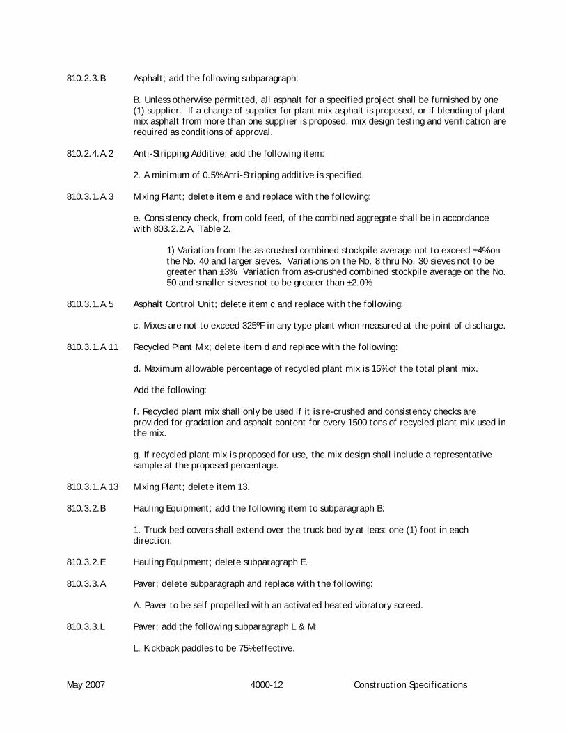
May 2007 4000-12 Construction Specifications
810.2.3.B Asphalt; add the following subparagraph: B. Unless otherwise permitted, all asphalt for a specified project shall be furnished by one
(1) supplier. If a change of supplier for plant mix asphalt is proposed, or if blending of plant mix asphalt from more than one supplier is proposed, mix design testing and verification are required as conditions of approval.
810.2.4.A.2 Anti-Stripping Additive; add the following item: 2. A minimum of 0.5% Anti-Stripping additive is specified. 810.3.1.A.3 Mixing Plant; delete item e and replace with the following:
e. Consistency check, from cold feed, of the combined aggregate shall be in accordance with 803.2.2.A, Table 2.
1) Variation from the as-crushed combined stockpile average not to exceed ±4% on the No. 40 and larger sieves. Variations on the No. 8 thru No. 30 sieves not to be greater than ±3%. Variation from as-crushed combined stockpile average on the No. 50 and smaller sieves not to be greater than ±2.0%.
810.3.1.A.5 Asphalt Control Unit; delete item c and replace with the following: c. Mixes are not to exceed 325ºF in any type plant when measured at the point of discharge. 810.3.1.A.11 Recycled Plant Mix; delete item d and replace with the following: d. Maximum allowable percentage of recycled plant mix is 15% of the total plant mix. Add the following:
f. Recycled plant mix shall only be used if it is re-crushed and consistency checks are provided for gradation and asphalt content for every 1500 tons of recycled plant mix used in the mix. g. If recycled plant mix is proposed for use, the mix design shall include a representative sample at the proposed percentage.
810.3.1.A.13 Mixing Plant; delete item 13. 810.3.2.B Hauling Equipment; add the following item to subparagraph B:
1. Truck bed covers shall extend over the truck bed by at least one (1) foot in each direction.
810.3.2.E Hauling Equipment; delete subparagraph E. 810.3.3.A Paver; delete subparagraph and replace with the following:
A. Paver to be self propelled with an activated heated vibratory screed. 810.3.3.L Paver; add the following subparagraph L & M: L. Kickback paddles to be 75% effective.

May 2007 4000-13 Construction Specifications
M. Paver shall be equipped with and utilize an operable grade reference device, having a minimum length of thirty (30) feet.
810.3.4.H Roller requirements; delete subparagraph H and replace with the following: H. Roller requirements
1. Vibratory roller speed shall be matched to vibrations per minute so that there are 10 to 14 vibrations per foot traveled (e.g. 3500 vpm = speed of 250 fpm to 350 fpm). 2. Vibratory rollers with pneumatic tire drive wheel to have smooth tires that leave no visible tracks. 3. No maximum speed is specified for pneumatic tired or steel track rollers. Contractor is responsible for meeting all density and smoothness requirements prior to acceptance by the District.
810.3.4.K Rollers; add the following subparagraph:
K. A Pneumatic tire roller is required in the compaction sequence. 810.3.5 Mix Design Approval; change section title to Mix Design Verification. 810.3.5 Mix Design Approval; delete subparagraph A and replace with the following:
A. Provide initial mix design and applicable tests performed by a WAQTC certified technician who has completed the ITD Mix Design Qualification Course (Level II) and follow all design procedures covered in this course. Mix design shall also be completed in a laboratory meeting the requirements of ASTM E 329 and D 3666 or that is certified by ITD for completing mix designs.
810.3.5 Mix Design Approval; delete the word “new” from subparagraph C. 810.3.5 Mix Design Approval; add the following subparagraphs:
F. Mix design specimens shall have a minimum two (2) hour cure time. G. Anticipated aggregate breakdown shall be included in the mix design.
H. The job-mix aggregate proportioning and mix design shall be determined by personnel meeting the requirements of 810.3.5.A and approved by the Engineer and the District prior to start of paving operations.
810.3.6.B Mixing; delete subparagraph B and C and replace with the following:
B. The asphalt content average to be within ±0.2% (of four consecutive tests) with no single test to be more than ±0.3% of the Contractor’s Job Mix Formula (CJMF) as accepted by the District.
C. Moisture content of the mixture at the time of placement not to exceed 0.3%. 810.3.8 Spreading and Finishing; add the following subparagraphs: J. Adjacent lanes shall be paved within 48 hours.

May 2007 4000-14 Construction Specifications
K. At the end of each day the transverse joints shall be saw cut to a vertical edge and prepared before paving resumes.
L. Thickness Tolerances; 1. The average pavement thickness shall be within 0.25 inches of the specified
thickness with no location varying more that ± 0.35 inches for roadways with 3 inch minimum specified thickness.
2. The average pavement thickness shall be within 0.20 inches of the specified
thickness with no location more than ± 0.25 inches for roadways with less than 3 inch minimum specified thickness.
3. Pavement not meeting the specified tolerance shall be removed and repaved or
overlaid as determined by the District.
810.3.9.A Weather Limitation and Cutoff Dates; delete subparagraph A and replace with the following:
A. Do not place pavement on a wet or frozen subgrade or gravel base course nor use frozen
aggregates in the mix. 810.3.9.C Weather Limitation and Cutoff Dates; delete subparagraph C. 810.3.9.D Weather Limitations and Cutoff Dates; delete subparagraph D and replace with the
following:
D. All re-paving of existing pavement surfaces shall be completed within 30 calendar days unless otherwise approved by the District.
810.3.10.D Joints; add the following to subparagraph D:
The material shall be a CSS-1 emulsified asphalt diluted 50% in accordance with Section 805. The application rate is 0.05 gal per square yard.
810.3.10.F Joints; delete subparagraph F and replace with the following:
F. The average of all unconfined edge densities shall meet 98% of the required mat density with no single joint density less than 95% of the required mat density. All core densities measures shall be centered 5” from free edge. Confined edge densities shall meet the mat density requirements.
810.3.11.K Compaction; delete subparagraph K and replace with the following: K. Begin rolling at the sides and proceed longitudinally parallel to the road centerline, with
each trip overlapping six (6) inches of the prior roller pass. 810.3.11.R Compaction; delete subparagraphs R and S and replace with the following:
R. The running average (of four consecutive tests) in place density shall be determined by the “Rice Method” (ASTM D 2041 or AASHTO T209) and shall be between 93% and 95% with no individual test less than 92.0% or greater than 96.0% for Class I & II pavements. The average of all density tests for Class III pavements shall be between 93% & 95% with no individual test less than 92.0% and greater than 96.0%. On projects having a total paving tonnage less than one thousand (1,000) tons the Class III requirements shall apply.

January 2010 4000-15 Construction Specifications
Roadways not meeting these compaction requirements will not be accepted into the District for maintenance.
810.3.13.A Field Quality Control; delete subparagraphs A and B and replace with the following:
A. All required observation and testing shall be in accordance with the requirements established in Division 5000 of the ACCHD Manual for Highway Standards and Development Procedures. As a minimum, one (1) sample shall be taken per day when the paving tonnage is under 750 tons per day, two (2) samples per day when the paving tonnage is over 750 tons per day, with one (1) additional sample being taken for every additional 750 tons placed per day over 1500 tons per day.
810.3.14.B.1 Surface Smoothness; delete items c and d and replace with the following: c. When straight edge is laid on the surface in a direction parallel or perpendicular to the
centerline, surface variations not to exceed 1/8” when perpendicular to centerline and 1/4” when parallel to centerline.
d. remove any highpoints found by grinding and add tack coat afterward at the rate of 0.05
gallons per square yard, at the Contractors expense. 810.3.14.B.2 Surface Smoothness; delete the first sentence section and replace with the following: Profile the surface of all arterials, and collectors (and all other roadways specified on the
plans) in accordance with Idaho T-140 and the following provisions, unless otherwise approved by the Engineer and the District.
Surface smoothness shall be verified by the International Roughness Index (IRI) with the following smoothness schedule:
International Roughness Index (IRI): Target IRI values - 7.1 to 8.0 in/0.1 mile. Corrective action required above 9.5 in/0.1 mile.
Consecutive 0.1- mile sections of roadway tested will be added together to obtain the mile section. There will be no overlapping of either the 0.1-mile or 1-mile sections to change cumulative test results.
Acceptance surface smoothness testing results shall be performed on the final lift and submitted to the District prior to any corrective action. Acceptance testing shall be completed within one (1) week after completion of paving.
All acceptance surface smoothness testing must be verified. The profile run must be witnessed by the District and a preliminary copy of the report and the graph chart shall be submitted to the District immediately after the end of the run. This testing will not be accepted unless witnessed by the District. At the District’s request, the profile data shall be submitted in a format suitable for evaluation using Proval or other acceptable software.
The pavement shall be profiled to provide continuous uninterrupted profile data. All pavement shall meet the profile smoothness requirements except for the following areas:
a. Pavement within 50 feet of a transverse joint that separates the pavement from a structure deck, an approach slab, or an existing pavement not constructed under the contract.

January 2010 4000-16 Construction Specifications
b. Pavement for structure decks.
Smoothness acceptance for these areas (a and b above) will be in accordance with straight-edge requirements.
Pavement for approaches shall not be profiled.
Profilers shall be a Class I or Class II as defined by ASTM E950. Profilers shall be operated in accordance with the manufacturer’s instructions and AASHTO PP-50. Profiler settings shall be as follows:
High Pass or pre-filter - off or a minimum of 200 ft. (61m) Bump detection - on Dip detection – on Resolution - 0.01 (0.25mm) Low Pass filter – off All Other filters – off
Profiles shall be made 3 feet from and parallel to each edge of each traffic lane. The average of the results for each 0.1-mile section will be used to determine sections requiring corrective action
The profiling equipment shall be operated at a speed no greater than that recommended by the manufacturer. It shall be calibrated at the beginning of the project and as needed thereafter.
Individual high points in excess of 0.3-inch within a 25 foot distance or less, as determined by the California Profilograph simulation, shall be reduced by grinding until such high points do not exceed 0.3-inch.
After grinding has been completed to reduce individual high points in excess of 0.3-inch, additional grinding shall be performed in sections requiring corrective action to reduce the IRI to a maximum of 8.0 inches in any 0.1-mile section along any line parallel with the pavement edge.
All grinding shall be done parallel to centerline. Adjacent grinder passes within any single ground area shall be extended to produce a neat rectangular area having a uniform surface appearance. At transverse boundaries between ground and unground areas, smoothly feathered transitions shall be made.
After grinding has been completed, the ground pavement surface shall receive a fog coat of CSS-1 in accordance with Section 813 – Fog Coat at a rate approved by the District.
The Contractor shall check the pavement for smoothness after grinding, in accordance with the requirements of this specification and shall make any additional corrections necessary to the pavement to achieve smoothness. The Contractor shall submit a report and a graph chart showing compliance of the final surface to the smoothness requirements.
The cost of such grinding or milling, and all related work such as fog coat, disposal of milled material, traffic control, flagging, profiling, surface repair of ground or milled areas, and temporary pavement markings shall be at the Contractor expense.
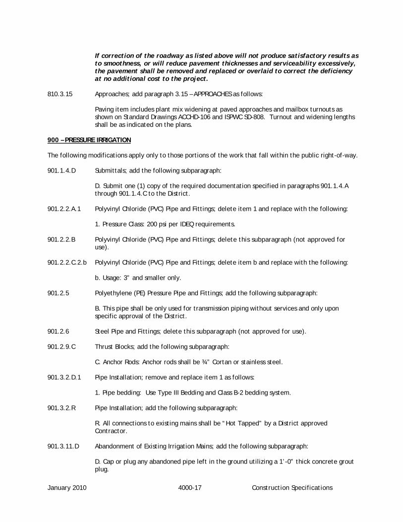
January 2010 4000-17 Construction Specifications
If correction of the roadway as listed above will not produce satisfactory results as to smoothness, or will reduce pavement thicknesses and serviceability excessively, the pavement shall be removed and replaced or overlaid to correct the deficiency at no additional cost to the project.
810.3.15 Approaches; add paragraph 3.15 – APPROACHES as follows:
Paving item includes plant mix widening at paved approaches and mailbox turnouts as shown on Standard Drawings ACCHD-106 and ISPWC SD-808. Turnout and widening lengths shall be as indicated on the plans.
900 – PRESSURE IRRIGATION The following modifications apply only to those portions of the work that fall within the public right-of-way. 901.1.4.D Submittals; add the following subparagraph:
D. Submit one (1) copy of the required documentation specified in paragraphs 901.1.4.A through 901.1.4.C to the District.
901.2.2.A.1 Polyvinyl Chloride (PVC) Pipe and Fittings; delete item 1 and replace with the following: 1. Pressure Class: 200 psi per IDEQ requirements. 901.2.2.B Polyvinyl Chloride (PVC) Pipe and Fittings; delete this subparagraph (not approved for
use). 901.2.2.C.2.b Polyvinyl Chloride (PVC) Pipe and Fittings; delete item b and replace with the following: b. Usage: 3” and smaller only. 901.2.5 Polyethylene (PE) Pressure Pipe and Fittings; add the following subparagraph:
B. This pipe shall be only used for transmission piping without services and only upon specific approval of the District.
901.2.6 Steel Pipe and Fittings; delete this subparagraph (not approved for use). 901.2.9.C Thrust Blocks; add the following subparagraph: C. Anchor Rods: Anchor rods shall be ¾” Cortan or stainless steel. 901.3.2.D.1 Pipe Installation; remove and replace item 1 as follows: 1. Pipe bedding: Use Type III Bedding and Class B-2 bedding system. 901.3.2.R Pipe Installation; add the following subparagraph: R. All connections to existing mains shall be “Hot Tapped” by a District approved
Contractor. 901.3.11.D Abandonment of Existing Irrigation Mains; add the following subparagraph:
D. Cap or plug any abandoned pipe left in the ground utilizing a 1’-0” thick concrete grout plug.

May 2007 4000-18 Construction Specifications
902.1.3.A References; delete this subparagraph. 902.1.4.D Submittals; add the following subparagraph:
D. Submit one (1) copy of the required documentation specified in paragraphs 902.1.4.A through 902.1.4.C to the District.
902.2.6.A Valve Boxes; modify subparagraph A to read as follows: A. All areas. 902.2.6.B Valve Boxes; delete this subparagraph. 903.1.4.D Submittals; add the following subparagraph:
D. Submit one (1) copy of the required documentation specified in paragraphs 903.1.4.A through 903.1.4.C to the District.
903.2.2.A PVC Pipe and Fittings for Irrigation Water Services; delete this subparagraph (not approved for use)
903.2.2.B Service Pipe and Fittings; delete items 1 and 2 and replace with the following: 1. Pressure Class: 200 psi 2. Outside Dimension Ratio: DR 7 903.2.3.A Appurtenances; delete subparagraph A and replace with the following: A. Service Saddles for PVC Main. Shall meet the requirements of Section 404 – Water
Service Lines and Meters. 903.2.3.B Appurtenances; delete this subparagraph. 903.2.3.E Appurtenances; delete subparagraph E and replace with the following: E. Service Valve Box for Irrigation Riser. 1. Size and Type: 4” PVC Pipe per ANSI/ASTM D 3034 or 3” class 160 PVC.
2. Marking Tag: “Irrigation – Non-Potable, Do not Drink” secured to curb stop box lid with number 8 x 1” screw.
3. Option A. – Faucets – hand marking tab with nylon cable tie. 4. Threaded plug and raised nut required PVC to match pipe.
903.2.3 Appurtenances; add the following subparagraphs: F. Service Ball Valves 1. 1” service - Ford B11-444, Mueller B-20283 2. 1 ½” Service - Ford B11-666, Mueller B-20283

May 2007 4000-19 Construction Specifications
3. 2” Service - Ford B11-777, Mueller B-20283 G. Faucets 1. NIBCO 74-CL 2. B-K Boiler, Heavy Duty 102-704 903.3.2.A Installation; delete subparagraph A and replace with the following:
A. Install per Standard Drawing SD-901. For services above one (1) inch in size, seek approval of District.
903.3.2.G Installation; delete items 1 and 2. 903.3.2. Installation; add the following subparagraph:
L. No service line joints shall be located within the public road right-of-way.
1000 – CONSTRUCTION STORMWATER BEST MANAGEMENT PRACTICES 1001.1.4.E Submittals; add the following subparagraph:
E. Submit one (1) copy of the required documentation specified in paragraphs 1001.1.4.A through 1001.1.4.D to the District.
1002.1.4.E Submittals; add the following subparagraph:
E. Submit one (1) copy of the required documentation specified in paragraphs 1002.1.4.A through 1002.1.4.D to the District.
1003.1.4.E Submittals; add the following subparagraph:
E. Submit one (1) copy of the required documentation specified in paragraphs 1003.1.4.A through 1003.1.4.D to the District.
1004.1.4.F Submittals; add the following subparagraph:
F. Submit one (1) copy of the required documentation specified in paragraphs 1004.1.4.A through 1004.1.4.E to the District.
1005.1.4.E Submittals; add the following subparagraph:
E. Submit one (1) copy of the required documentation specified in paragraphs 1005.1.4.A through 1005.1.4.D to the District.
1006.1.4.F Submittals; add the following subparagraph:
F. Submit one (1) copy of the required documentation specified in paragraphs 1006.1.4.A through 1006.1.4.E to the District.
1007.1.4.E Submittals; add the following subparagraph:
E. Submit one (1) copy of the required documentation specified in paragraphs 1007.1.4.A through 1007.1.4.D to the District.
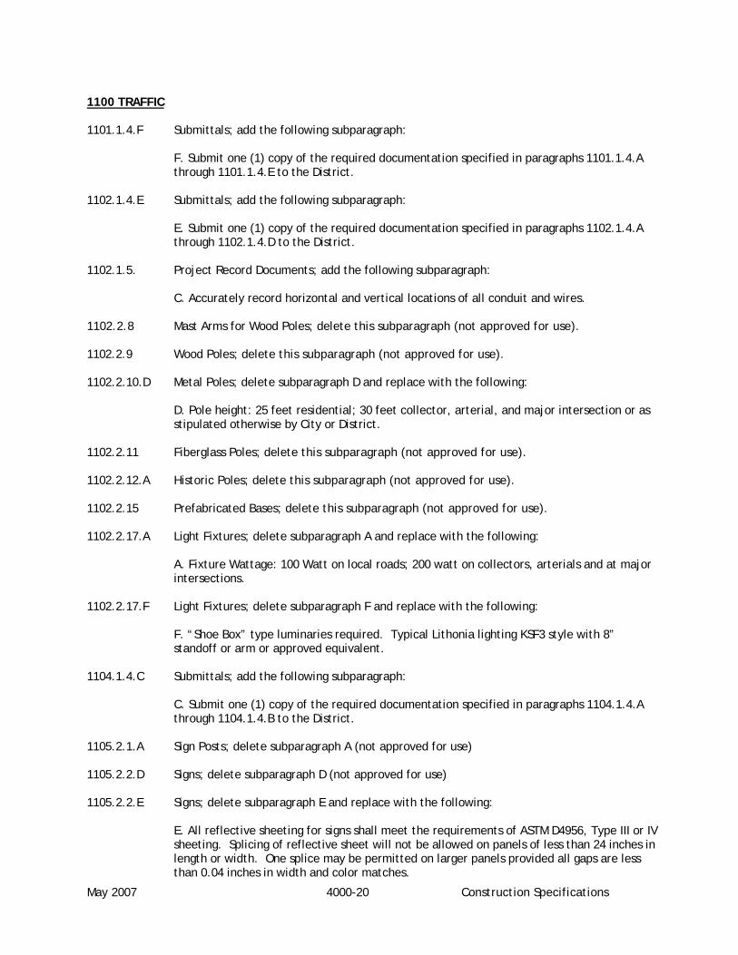
May 2007 4000-20 Construction Specifications
1100 TRAFFIC 1101.1.4.F Submittals; add the following subparagraph:
F. Submit one (1) copy of the required documentation specified in paragraphs 1101.1.4.A
through 1101.1.4.E to the District. 1102.1.4.E Submittals; add the following subparagraph:
E. Submit one (1) copy of the required documentation specified in paragraphs 1102.1.4.A
through 1102.1.4.D to the District. 1102.1.5. Project Record Documents; add the following subparagraph: C. Accurately record horizontal and vertical locations of all conduit and wires. 1102.2.8 Mast Arms for Wood Poles; delete this subparagraph (not approved for use). 1102.2.9 Wood Poles; delete this subparagraph (not approved for use).
1102.2.10.D Metal Poles; delete subparagraph D and replace with the following:
D. Pole height: 25 feet residential; 30 feet collector, arterial, and major intersection or as stipulated otherwise by City or District.
1102.2.11 Fiberglass Poles; delete this subparagraph (not approved for use). 1102.2.12.A Historic Poles; delete this subparagraph (not approved for use). 1102.2.15 Prefabricated Bases; delete this subparagraph (not approved for use). 1102.2.17.A Light Fixtures; delete subparagraph A and replace with the following:
A. Fixture Wattage: 100 Watt on local roads; 200 watt on collectors, arterials and at major intersections.
1102.2.17.F Light Fixtures; delete subparagraph F and replace with the following:
F. “Shoe Box” type luminaries required. Typical Lithonia lighting KSF3 style with 8” standoff or arm or approved equivalent.
1104.1.4.C Submittals; add the following subparagraph:
C. Submit one (1) copy of the required documentation specified in paragraphs 1104.1.4.A through 1104.1.4.B to the District.
1105.2.1.A Sign Posts; delete subparagraph A (not approved for use) 1105.2.2.D Signs; delete subparagraph D (not approved for use) 1105.2.2.E Signs; delete subparagraph E and replace with the following:
E. All reflective sheeting for signs shall meet the requirements of ASTM D4956, Type III or IV sheeting. Splicing of reflective sheet will not be allowed on panels of less than 24 inches in length or width. One splice may be permitted on larger panels provided all gaps are less than 0.04 inches in width and color matches.

May 2007 4000-21 Construction Specifications
1105.3.2.A Sign Installation; delete subparagraph A (not approved for use) 1105.1.4.C Submittals; add the following subparagraph:
C. Submit one (1) copy of the required documentation specified in paragraphs 1105.1.4.A through 1105.1.4.B to the District.
2050 CONSTRUCTION GEOTEXTILES 2050.1.5.B Submittals; add the following subparagraph:
B. Submit one (1) copy of the required documentation specified in paragraph 2050.1.5.A to the District.
2060 GUARDRAIL Add section 2060 as follows: PART 1 GENERAL
1.1 SECTION INCLUDES
A. Guardrail
B. Guardrail End Treatments
C. Guardrail Hardware
D. Post Materials
E. Spacer Block Materials
F. Preservation Treatments
G. Construction Requirements
1.2 RELATED SECTIONS
A. Section 202 — Excavation and Embankment
1.3 REFERENCES
A. AASHTO M180
B. ASTM A153 — Zinc Coating (Hot Dip) Iron and Steel Hardware
C. ASTM A307
D. ASTMA325
E. NCHRP 350, TL3
F. AWPAP8, P9 and C14
G. AWPA Standard C2 1.4 GENERAL REQUIREMENTS

May 2007 4000-22 Construction Specifications
A. All guardrail shall be galvanized steel. B. Posts shall be wood or galvanized steel.
C. Spacer blocks shall be wood or polyethylene plastic.
D. All hardware shall be galvanized steel.
1.5 SUBMITTALS
A. Submit manufacturer’s certification that posts, spacer blocks, guardrail, end treatments and all hardware meet or exceed specified requirements. B. Submit manufacturer’s installation instructions and maintain a copy at the jobsite.
C. Submit a copy of items 2060.1.5.A and 2060.1.5.B, above, to the District.
PART 2 MATERIALS
2.1 GUARDRAIL
A. Guardrail Beams shall meet the specifications for AASHTO Ml 80, Class A, Type I.
B. The rail element shall not deflect more than 5.5 inches when tested as a simple beam with the traffic face up and with a 2,000 lb load applied at the center of a 12 ft. clear span, through a 3 inch wide flat bearing.
2.2 GUARDRAIL END TREATMENTS
A. Type 1A (NOT NCHRP 350 Compliant).
1. May only be used where not exposed to approaching traffic.
B. Type 10 (NCHRP 350, TL-3 Compliant).
1. ET-2000 2. SKT-350 3. LET
2.3 GUARDRAIL HARDWARE
A. Bolts, nuts and washers used shall conform to ASTM A 307 or A 325, except that rail splice bolts shall be button headed. Bolts, nuts, washers and other fittings used shall be galvanized in accordance with ASTM A 153.
2.4 POST MATERIALS
A. Wood Posts. Wood posts shall be rough, S2S or S4S. Size tolerance of rough sawn blocks in the direction of the bolt holes is ± ¼ in. Incising requirements shall be as specified in Standard C2 of The American Wood Preservers Association (AWPA) and treated according to section 2060.2.6.A of this specification. Post length shall be as shown on the plans. B. Metal Posts. Metal posts shall be W6x8.5 or W6x9 galvanized steel. Post length shall be as indicated on the plans.

January 2010 4000-23 Construction Specifications
2.5 SPACER BLOCK MATERIALS
A. Wood Spacer Blocks. Wood spacer blocks shall be rough, S2S or S4S. Size tolerance of rough sawn blocks in the direction of the bolt holes is ± ¼ in. Incising requirements shall be as specified in Standard C2 of The American Wood Preservers Association (AWPA) and treated according to section 2060.2.6.A of this specification.
B. Metal Spacer Blocks. Metal spacer blocks are not allowed.
C. Polyethylene Spacer Blocks. Polyethylene spacer blocks shall be impervious to moisture. Polyethylene spacer blocks shall have passed the test requirements of NCHRP 350, TL-3.
2.6 PRESERVATION TREATMENTS
A. Wood guardrail posts and spacer blocks shall be pressure treated with pentachlorophenol or copper naphthenate in accordance with the latest version of AWPA standards P-8, P-9 and C-14; except the minimum retention of preservative as determined by assay shall be 0.50 pounds per cubic foot of wood for pentachlorophenol and 0.60 pounds per cubic foot of wood for copper naphthenate.
PART 3 WORKMANSHIP
3.1 DESCRIPTION
A. This work shall consist of furnishing and erecting guardrail in accordance with these specifications and in reasonably close conformance to the lines and grades shown on the plans or established by the Engineer.
3.2 CONSTRUCTION REQUIREMENTS
A. Posts shall be spaced as shown on the plans and be set plumb and to the established lines and grades. Backfill material shall then be placed in layers and thoroughly tamped. Boring of wood posts and spacer blocks should be done prior to preservative treatment, but field boring will be permitted providing the hole is treated per section 2060.2.6.A of these specifications, creosoted before driving the bolts.
B. Posts may be driven if this can be done without damage to posts, pavement, shoulders or adjacent slopes. If pilot holes are necessary to prevent such damage, fill any remaining voids between post and soil with dry sand or pea gravel. Misaligned, loose or damaged posts shall be removed, replaced or reinstalled at the Contractor’s expense. Any damage to existing pavement or base shall be repaired at the contractor’s expense.
PART 4 MEASUREMENT AND PAYMENT
4.1 Use one or more of the following unit prices as designated in the Bid Schedule. Includes all labor, materials and equipment required to perform the work as specified. If required and not listed in the Bid Schedule, the following Bid Items are to be considered incidental to other Bid Items.
A. Guardrail: Measured by the linear foot complete and in place including excluding the length of rail in terminal sections.
1. Bid Schedule Payment Reference: 2060.4.1 .A. 1
2. Bid Schedule Description: Guardrail, linear foot (LF)

May 2007 4000-24 Construction Specifications
B. Guardrail End Terminal: Measured by each unit installed complete in place and in conformance with these specifications.
1. Bid Schedule Payment Reference: 2060.4.1.B.1 2. Bid Schedule Description: Guardrail End Treatment, Type ___, each (EA).

May 2007 5000-1 Construction Quality Assurance
SECTION 5000
CONSTRUCTION QUALITY ASSURANCE
5010. Purpose
5010.010. The purpose of this policy statement is to outline the minimum acceptable level of
observation to be performed on all roadway construction activities performed within the boundaries of
the District. Minimum testing frequencies are also included in this policy statement. However, the
ISPWC or Section 4000 of these standards may impose more frequent or additional testing requirements.
5020. Construction Responsibilities
5020.010. Applicant’s Responsibilities: The Applicant has the following responsibilities during the
construction of the development:
A. Prior to commencement of construction, the Applicant shall have the improvement drawings
accepted by the District.
B. The Applicant shall perform all construction in accordance with accepted plans,
specifications, standards and policies.
C. The Applicant shall provide reasonable access for District personnel during the course of the
project.
D. Prior to acceptance of the Roadway by the District the applicant shall execute the Financial
Guarantee Agreement.
5020.020. District’s Responsibilities: The District has the following responsibilities during the
construction of the development:
A. Prior to commencement of construction, the District shall review for acceptance the
improvement drawings.
B. The District shall review for acceptance locations of all traffic control signing.
C. The District shall review for acceptance design changes during construction which have been
approved by the Applicant's Engineer.
D. The District shall make periodic observations during construction to monitor general
compliance with specifications.

May 2007 5000-2 Construction Quality Assurance
E. Upon notice from the Applicant's Engineer that the project is substantially complete and upon
receipt of the Applicant's Engineer's punch list, the District will perform a pre-final review and
provide copies of the results to the Applicant's Engineer.
F. The District shall consider for approval a Financial Guarantee Agreement with the applicant in
a form approved by the District.
5020.030. Applicant’s Engineer’s Responsibilities: The Applicant’s Engineer has the following
responsibilities during the construction of the development:
A. The Applicant’s Engineer shall be responsible for full compliance with the requirements of this
Section.
B. The Applicant’s Engineer shall be responsible for all observations, inspections and records at
the minimum intervals presented in this policy statement.
C. The Applicant’s Engineer shall accept or reject work performed based on observations,
inspections and test results.
D. The Applicant’s Engineer shall assure all necessary construction surveying for the project is
provided.
E. The Applicant’s Engineer shall provide to the District certified test results.
F. The Applicant’s Engineer shall schedule and coordinate a pre-construction conference.
G. The Applicant’s Engineer or their field representative shall maintain a project diary containing
necessary project information.
H. The Applicant’s Engineer shall provide 24-hour notification to the District for the various
stages of construction to facilitate observations by the District.
I. The Applicant’s Engineer shall submit all manufacturers’ certificates for materials supplied to
the project.
J. The Applicant’s Engineer shall prepare the required post-construction documentation and
submit to the District for final acceptance of the roadway.
5030. Pre-Construction Conference
5030.010. A pre-construction conference shall be held on all projects a minimum of two (2) days prior
to commencing any construction on the project. An agenda is provided in these standards for use in
conducting the pre-construction conference and should generally be followed. At a minimum, the
following shall attend the pre-construction conference:
A. Developer/Applicant

May 2007 5000-3 Construction Quality Assurance
B. Applicant’s Engineer
C. District Representative(s)
D. Contractor
E. Joint Utility Trench Coordinator (or designated representative)
F. Sub-Contractors (Optional)
5040. Submittals
5040.010. Submittals shall be provided to the District in accordance with the following:
A. A minimum of one (1) week prior to scheduled use of the materials on the project for
standard materials (not project specific – mix design, base, sub-base, etc. as required by the
ISPWC and Section 4000 modifications)
B. Project specific pre-cast structures or other fabricated components shall be submitted to
provide a minimum of two (2) weeks review.
5050. Construction Observation Diary
5050.010. The Applicant’s Engineer or field representative shall be responsible for keeping a project
journal during construction, which shall include at a minimum the following information:
A. Date and work performed.
B. Weather conditions.
C. Operations being performed and location of work on project.
D. Measurements and/or observations made to assure compliance with the plans and
specifications.
E. Discussions, decisions or directives made regarding the design or construction of the project.
F. Unusual conditions or changes.
G. Other relative information.
A copy of the diary shall be filed with the District at the completion of the project.5060. Testing Results
5060. Testing Results
5060.010. Test results and special inspection reports required shall be provided to the Highway District
and Applicant’s Engineer with 48 hours after testing. Test results shall include at a minimum the
following information:
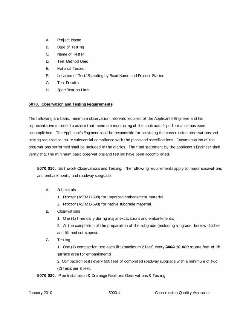
January 2010 5000-4 Construction Quality Assurance
A. Project Name
B. Date of Testing
C. Name of Tester
D. Test Method Used
E. Material Tested
F. Location of Test/Sampling by Road Name and Project Station
G. Test Results
H. Specification Limit
5070. Observation and Testing Requirements
The following are basic, minimum observation intervals required of the Applicant's Engineer and his
representative in order to assure that minimum monitoring of the contractor's performance has been
accomplished. The Applicant's Engineer shall be responsible for providing the construction observations and
testing required to insure substantial compliance with the plans and specifications. Documentation of the
observations performed shall be included in the diaries. The final statement by the applicant's Engineer shall
verify that the minimum basic observations and testing have been accomplished.
5070.010. Earthwork Observations and Testing: The following requirements apply to major excavations
and embankments, and roadway subgrade:
A. Submittals
1. Proctor (ASTM D-698) for imported embankment material.
2. Proctor (ASTM D-698) for native subgrade material.
B. Observations
1. One (1) time daily during major excavations and embankments.
2. At the completion of the preparation of the subgrade (including subgrade, borrow ditches
and fill and cut slopes).
C. Testing
1. One (1) compaction test each lift (maximum 2 feet) every 3000 10,000 square feet of lift
surface area for embankments.
2. Compaction tests every 500 feet of completed roadway subgrade with a minimum of two
(2) tests per street.
5070.020. Pipe Installation & Drainage Facilities Observations & Testing

January 2010 5000-5 Construction Quality Assurance
A. Submittals
1. Pipe, fittings or minor structure manufacturer’s data as required by District.
2. Proctor for backfill material.
B. Observations
1. At completion of trench excavation, prior to placement of pipe.
2. One (1) time per day during installation of pipe and pipe bedding.
3. At every manhole or catch basin prior to backfill.
4. All thrust blocks prior to backfill.
C. Testing
1. Pipe Testing
a. Shall be perform in the presence of the Engineer.
b. Clean pipe per ISPWC Section 501.3.4.F.
c. Visually inspect pipe per ISPWC Section 501.3.4.B for alignment and grade, pipe
distortions, leaks, infiltration, and that a full diameter of pipe is visible from one
manhole to the next.
d. Low pressure air, hydrostatic, and mandrel testing will be used to confirm
compliance.
2. Trench Backfill.
a. A minimum of one (1) compaction test per backfill layer is required for any trench
backfill including “Bell Holes”.
b. For all other trench backfill compaction testing must be performed at the
following frequency:
1. Two (2) tests, at different locations for every trench less than 500 feet in
length, but not less than one (1) time per day.
2. One (1) test per every 500 feet of additional trench and at locations where
materials or construction procedures change, but not less than one (1) time
per day.
3. At every location for 1 and 2 above, obtain a test at ½ of the total trench
depth and one (1) test at the top of the trench backfill (test set).
5070.030. Road Base Observations & Testing: The following requirements apply to the Sub-Base and
Base Course.
A. Submittals (Each source or change in material)

May 2007 5000-6 Construction Quality Assurance
1. Gradation (Sieve Analysis) and Sand Equivalent.
2. Proctor (ASTM D-698).
B. Observations
1. At completion of each lift.
C. Testing
1. Compaction tests every 500 feet of roadway per lift of material with a minimum of two (2)
tests per street.
5070.040. Structures
A. Submittals
1. Concrete Mix Design.
B. Construction Observations
1. Structure foundation conditions shall be verified by the Geotechnical Engineer for
consistency with the design parameters prior to forming footings/foundations.
2. After completion of forming and reinforcing placement, but prior to placement of
concrete.
3. Once per day during placement of concrete.
4. After placement of concrete and striping forms, but prior to backfill placement.
C. Testing
1. Slump, temperature and entrained air at least each pour less than 50 cubic yards and once
per each additional 50 cubic yards.
2. Compressive Strength cylinders and tests at least each pour less than 50 cubic yards and
once per each additional 50 cubic yards.
5070.050. Curb, Gutter and Sidewalk
A. Submittals
1. Concrete Mix Design.
B. Construction Observations
1. After completion of forming or establishment of grade line, but prior to placement of
concrete.
2. At least one (1) time per day during placement.
C. Testing

January 2010 5000-7 Construction Quality Assurance
1. Compaction test on curb and gutter base course at least one (1) time every 300 feet of
curb.
2. Slump, temperature, entrained air, and compressive strength cylinders and tests as
required by the District.
5070.060. Paving
A. Submittals
1. Asphalt Concrete Mix Design.
B. Construction Observations
1. At commencement of paving operation on the project.
2. One (1) time per day during the placement.
C. Testing
1. Density tests at commencement of the paving operations until an acceptable roller pattern
is developed and at least one (1) for every 300 feet throughout project.
2. Extraction and gradation at least one (1) for every 2,000 feet of roadway, but not less than
one (1) each day of paving operations.
3. Core of in-place pavement at least one (1) for every 1,000 feet of roadway with a
minimum of two (2) tests per street. In-place air voids shall be tested with each core test.
D. Thickness Tolerances (based on core samples)
1. The average pavement thickness shall be within 0.25 inches of the specified thickness with
no location varying more that ± 0.35 inches for roadways with 3 inch minimum specified
thickness.
2. The average pavement thickness shall be within 0.20 inches of the specified thickness with
no location more than ± 0.25 inches for roadways with less than 3 inches minimum specified
thickness.
3. Pavement not meeting the specified tolerance shall be removed and repaved or overlaid as
determined by the District.
5070.070. Surface Restoration Testing
A. Submittals
1. Base
a. Gradation (Sieve Analysis) and Sand Equivalent.
b. Proctor.
2. Paving

May 2007 5000-8 Construction Quality Assurance
a. Asphalt Concrete Mix Design.
B. Construction Observations
1. Base
a. At completion of each lift.
1. Paving
a. At the commencement of paving operation on the project.
b. Once per day during the placement.
C. Testing
1. A minimum of one (1) compaction test of the base course and one (1) compaction test of
the pavement for surface repairs less than 50 feet in length.
2. Compaction testing shall be performed on the base course at the following minimum
frequencies:
a. Two (2) tests at different locations for every surface repair less than 500 feet in
length but not less than one (1) time per day.
b. One (1) test per every 500 feet of additional surface repair and at locations where
materials or construction methods change, but not less than once per day.
3. Compaction testing shall be performed on the pavement surface at the following minimum
frequencies:
a. Two (2) tests at different locations for every surface repair less than 300 feet in
length, but not less than one (1) time per day.
b. One (1) test per every 300 feet of additional surface repair and at locations where
materials or construction methods change, but not less than one (1) time per day.
5080. Pre-Acceptance Final Review
5080.010. After substantial completion of the project, including all paving, drainage, and traffic control
sign installation, a pre-acceptance final review shall be conducted on the project site. The following
shall attend the pre-acceptance final review:
A. District Representative
B. Applicant’s Engineer
C. Contractor
D. Developer/Applicant (Optional)
May 2007 5000-9 Construction Quality Assurance
5090. Post Construction Submittal
5090.010. On completion of the project, the Applicant’s Engineer shall provide the post-construction
submittal to the District. Consideration of acceptance of the roads will not occur until an acceptable
post construction submittal is provided to the District. The post construction submittal shall include the
following:
A. A statement that all work performed during the project was in accordance with project plans
and specifications, and that the minimum testing and inspections were performed in
accordance with this policy statement. The form of the statement is to be specified by the
District.
B. Record drawings on Mylar and electronic copy on CD/DVD as required under Section 2000.
C. A copy of the Construction Observation Diary for the project.
D. A copy of the test results for the project.

May 2007 5000-10 Construction Quality Assurance
ENGINEER'S STATEMENT Name of Project Applicant Engineer I hereby state the following: 1. Observation was performed substantially to at least the basic minimum construction
observation intervals established by the District. 2. Construction practices and materials observed were in compliance with the approved plans
and specifications. 3. Construction was performed substantially to the lines and grades shown on the approved plans
or as approved by the District. 4. Based on tests performed, the asphalt pavement meets the District Standards. 5. A Record Drawing (three copies) has been submitted to the District. One (1) copy must be on
archival media (e.g. Mylar, etc.) and one (1) electronic copy (CD/DVD). 6. A copy of the construction diary has been submitted to the District. Any of the above items which cannot be fully satisfied shall be explained on a separate sheet of paper and attached hereto. Attachments: yes no Signature of Engineer Date

May 2007 6000-1 Definitions
SECTION 6000
DEFINITIONS
AASHTO – American Association of State Highway Transportation and Officials.
Applicant - Any person, persons or firm making application to the District.
Area of City Impact – Those areas outside of current city limits that the city and county mutually administer
to plan for future growth (I.C. 67-6526).
City – Any of the incorporated Cities within Canyon County, Idaho.
Developer - Any person, persons or firm making application to the District.
Development – Any activity within the District requiring application to the District, review by the District or
approval of the District, including but not limited to approach construction or improvements, roadway
construction or improvements, utility construction or improvements, subdivision of land by plat or other legal
methods and all other activities affecting District right-of-way, right-of-way dedication, right-of-way vacation
or right-of-way access.
Dedication - The setting apart of land or interest in land for use by the public. Land becomes dedicated when
accepted by the District as a public dedication, either by ordinance, resolution or entry in the official minutes,
or by the recording of a plat showing such dedication.
Easement - A grant by the owner of the use of a parcel of land by the public, corporation or persons for
specified use and purposes.
Engineer – A Professional Engineer licensed to practice within the State of Idaho or authorized to provide
services within the State of Idaho by the Idaho Board of Professional Engineers and Professional Land
Surveyors.
Frontage – The extent of District right-of-way contiguous with any portion of a development.

May 2007 6000-2 Definitions
Highway District (District) - Any one of the following official Highway Districts within Canyon County, Idaho.
Nampa Highway District No. 1
Notus-Parma Highway District No. 2
Golden Gate Highway District No. 3
Canyon Highway District No. 4
ISPWC – Idaho Standards for Public Works Construction (latest edition).
LHTAC – Local Highway Technical Assistance Council, 3330 Grace Street, Boise, ID 83703. Phone (208) 344-
0565, Fax (208) 344-0789.
Irrigation Facilities – Includes canals, laterals, ditches, conduits, gates, wells, pumps and allied equipment
necessary for the supply, delivery and drainage of irrigation water.
Local Highway Jurisdictions, (LHJ) - The city or District having jurisdiction over the public highways, streets
and rights-of-ways.
Minor Utilities – Utility lines serving a single parcel of land or two single residential parcels, expect gas lines
greater than 2-inches in diameter.
Owner - The person or persons holding title by deed to land or holding title as vendees under land contract.
Plat - A map of a subdivision.
Preliminary Plat - A preliminary map, including supporting data, indicating a proposed subdivision
development, prepared in accordance with Canyon County ordinances and the Idaho Code.
Final Plat - A map of all or part of a subdivision providing substantial conformance to an approved
preliminary plat, prepared by a Registered Professional Land Surveyor in accordance with Canyon County
ordinances and the Idaho Code.
Recorded Plat - A final plat bearing all of the certificates of approval required by ordinance and duly
recorded in the County Recorder’s Office.
Public Right-of-Way (right-of-way) - A right-of-way open to the public and under the jurisdiction of a public
highway agency, where the public highway agency has no obligation to construct or maintain said right-of-way
for vehicular traffic, nor shall there be any liability for any injury or damage for failure to maintain it or any
highway signs. [I.C. 40-117(6), I.C. 40-202(4) and I.C. 50-1301(7)].

May 2007 6000-3 Definitions
Reserve Strip - A strip of land between a dedicated street or partial street and adjacent property, in either
case, reserved or held in public ownership for future street extension or widening.
Right-of-Way - A parcel of land dedicated or reserved for use as a public way, which normally includes streets,
sidewalks, utilities or other service functions.
Roadway - Any street, avenue, boulevard, road land, parkway, place, viaduct, easement for access, or other
way which is an existing state, county, or municipal roadway; or a street or way shown in a plat heretofore
approved pursuant to law or approved by official action; or a street or way in a plat duly filed and recorded
within the right-of-way boundaries whether improved or unimproved and may be comprised of pavement,
shoulder, curbs, gutters, sidewalks, parking areas, and lawns.
Arterial Route - A general term including expressways, major and minor arterial streets, and interstate,
state or local highways having regional continuity.
Collector Street - A street that provides for traffic movement within neighborhoods of the District and
between major streets and local street and for direct access to abutting property.
Local Street - A street that provides for direct access to residential, commercial, industrial, or other
abutting land for local traffic movements and connects to collector and/or arterial streets.
Marginal Access Street - A minor street parallel and adjacent to an arterial route that intercepts local
streets and controls access to an arterial route.
Cul-de-Sac Street - A short local street having one end permanently terminated in a vehicular
turnaround.
Loop Street - A minor street with both terminal points on the same street of origin.
Alley - A public service way used to provide secondary vehicular access to properties otherwise abutting
upon a street.
Rural (Rural Roadway) – All areas and roadways not within one mile of an incorporated city limit or within a
city limit.

May 2007 6000-4 Definitions
Shall – Mandatory, same as “will”, as opposed to “may” or “should”.
Subdivider - A subdivider shall be deemed to be the individual, firm, corporation, partnership, association,
syndication, trust or other legal entity having sufficient proprietary rights in the property to represent the
owner, which submits the required subdivision application and initiates proceedings for the subdivision of land
in accordance with these procedures.
Subdivision - The division of any lot, tract or parcel of land into more than two (2) parts.
Terrain – The topography of the land traversed for the alignment of roads and streets. To characterize
variations in topography, engineers generally separate terrain into three classifications:
Level Terrain – Terrain where sight distances are generally long or can be made to be so without
construction difficulty.
Rolling Terrain – Terrain where natural slopes consistently rise above and fall below the road or street
grade, and occasional steep slopes offer some restriction to normal horizontal and vertical roadway
alignment.
Mountainous Terrain – Terrain where longitudinal and transverse changes in the elevation of the ground
with respect to the road or street are abrupt and benching and side hill excavation are frequently needed
to obtain acceptable horizontal and vertical alignment.
The Highway Commissioners shall have sole discretion on the determination of terrain classification for a
road.
Urban (Urban Roadway) – All areas and roadways within one mile of an incorporated city limit or within a city
limit.
Utilities - Installations or facilities, underground or overhead, furnished for use by the public, including but
not limited to, electricity, gas, steam, communications, water, drainage, irrigation, sewage disposal, or flood
control, owned and operated by any person, firm, corporation, municipal department, or board duly
authorized by state or municipal regulations. Utility or utilities as used herein may also refer to such persons,
firms, corporations, departments or boards, as applicable herein.

Form A (for use before acceptance of roadway)
A1
FINANCIAL GUARANTEE AGREEMENT THIS AGREEMENT, made this _____ day of _________________, 20___, by and between ____________________________, (hereinafter referred to as "Applicant") and the _____________________ Highway District No. ______ (hereinafter referred to as "District"), IT IS AGREED: 1. APPLICANT agrees to complete, or cause to be completed, the improvements as shown on Drawing(s) No. _____________, Sheet(s) ______ through ______, for ____________________________ (hereinafter referred to as "Project") and in accordance with all special conditions as set forth by the District as are on file in the office of the District, on or before the ______ day of _________________, 20___, or such later time as may be extended, in writing, by the District, including the installation of all necessary utility lines, structures and service connections directly associated with the project within the public rights-of-way and easements. 2. APPLICANT agrees to pay for all labor and material costs for completion of the improvements, and the improvements are to be completed free and clear of all liens, encumbrances, assessments or unpaid obligations. 3. APPLICANT agrees that all improvements listed herein shall be completed according to standard specifications adopted by the District and to pay, when due, all fees incurred or charged by the District in connection with this project. 4. APPLICANT has furnished the District with a cash deposit, Surety Bond, or irrevocable letter of credit issued by a financial institution authorized to do business in the State of Idaho, in a form approved by the District in the amount of $________________ (equal to 125% of the estimated cost of the “public or special improvements” included in the project). Said cash deposit, Surety Bond or letter of credit shall be in force until the construction is acceptable to the District. After acceptance of the roadway by the District, a cash deposit, Surety Bond or letter of credit in the amount of 50% of the construction cost1 of the improvements shall remain in effect for (1) one year, assuring performance of Applicant’s obligations under this agreement. “Public or special improvements” are defined as follows: road improvements operated and maintained by the District and others as follows: __________________________________________________________________________________________ __________________________________________________________________________________________ __________________________________________________________________________________________ In the event the Applicant fails to complete the "public or special improvements" as herein set out, the District, at its option, may complete the project, or cause it to be completed, and the cost thereof in labor, material costs and for the District to perform any observations, tests, and retests, whereby test results of the materials to be used and/or installed are shown not to conform to District’s detailed specifications, shall be the amount of liquidated damages, plus court costs and reasonable attorney fees incurred by the District in relation thereto, which amounts shall be a charge against the cash deposit, Surety Bond, or letter of credit. The Applicant shall be liable for any deficiency incurred over and above the amount of the cash deposit, bond or letter of credit furnished. 5. DISTRICT agrees that upon satisfactory completion of the improvements listed herein, in accordance with the specifications and requirements of said District, the District will be responsible for continuous maintenance of the public road(s) within the District's boundaries. 1 Construction cost to be verified by construction or bid

Form A (for use before acceptance of roadway)
A2
6. APPLICANT further agrees neither the final certificate of completion nor any provision within this agreement nor partial or entire use of the improvements embraced in this agreement by the District or the public shall constitute an acceptance of work not done in accordance with said approved drawings and District standards and specifications or relieve the Applicant of liability in respect to any or all warranties or responsibility for faulty materials or workmanship. The Applicant shall remedy or shall cause to be remedied promptly any defects in the work and to pay for any damage to other work resulting there from which shall appear within a period of one (1) year from the date of final acceptance of the improvements. The District will give notice of defective materials and work with reasonable promptness. 7. APPLICANT agrees that he shall retain a licensed, Professional Engineer who shall supervise the construction and provide an Engineer’s Statement indicating that all improvements are constructed in accordance with the accepted improvement drawings and the adopted District standards and that construction observation was in accordance with Section 5000 of the Highway Standards and Development Procedures for the Canyon County Highway Districts. IN WITNESS WHEREOF, the Parties hereto have executed this Agreement as of the date first written above.
________________________________________ Highway District No. _____ ______________________________________ CHAIRMAN ATTEST: ______________________________ ______________________________________ APPLICANT

Form B (for use after acceptance of roadway)
B1
FINANCIAL GUARANTEE AGREEMENT THIS AGREEMENT, made this _____ day of _________________, 20___, by and between ____________________________, (hereinafter referred to as "Applicant") and the _____________________ Highway District No. ______ (hereinafter referred to as "District"), IT IS AGREED: 1. APPLICANT has completed, or caused to be completed, the improvements as shown on Drawing(s) No. _____________, Sheet(s) ______ through ______, for ____________________________ (hereinafter referred to as "Project") and in accordance with all special conditions as set forth by the District as are on file in the office of the District, including the installation of all necessary utility lines, structures and service connections directly associated with the project within the public rights-of-way and easements. 2. APPLICANT has paid or agrees to pay for all labor and material costs for completion of the improvements, and the completed improvements are free and clear of all liens, encumbrances, assessments or unpaid obligations. 3. APPLICANT assures that all improvements listed herein are completed in according with the standard specifications adopted by the District and all fees incurred or charged by the District in connection with this project have been paid. Applicant further agrees to pay, when due, all additional fees incurred or charged by the District in connection with this project. 4. Upon acceptance of the roadway by the District, Applicant shall furnish a cash deposit, Surety Bond or irrevocable letter of credit issued by a financial institution authorized to do business in the State of Idaho, in a form approved by the District in the amount of 50% of the construction cost1 of the public or special improvements. This guarantee shall remain in effect for (1) one year, after acceptance of the roadway by the District, assuring performance of Applicant's obligations under this agreement. "Public or special improvements" are defined as follows: road improvements operated and maintained by the District and others as follows: __________________________________________________________________________________________ __________________________________________________________________________________________ __________________________________________________________________________________________ 5. DISTRICT agrees that upon satisfactory completion of the improvements listed herein, in accordance with the specifications and requirements of said District, the District will be responsible for continuous maintenance of the public road(s) within the District's boundaries. 6. APPLICANT further agrees neither the final certificate of completion nor any provision within this agreement nor partial or entire use of the improvements embraced in this agreement by the District or the public shall constitute an acceptance of work not done in accordance with said approved drawings and District standards and specifications or relieve the Applicant of liability in respect to any or all warranties or responsibility for faulty materials or workmanship. The Applicant shall remedy or shall cause to be remedied promptly any defects in the work and to pay for any damage to other work resulting there from which shall appear within a period of one (1) year from the date of final acceptance of the improvements. The District will give notice of defective materials and work with reasonable promptness. 7. APPLICANT assures that he retained a licensed, Professional Engineer who supervised the construction and provided an Engineer’s Statement indicating that all improvements are constructed in 1 Construction cost to be verified by construction or bid

Form B (for use after acceptance of roadway)
B2
accordance with the accepted improvement drawings and the adopted District standards and that construction observation was in accordance with Section 5000 of the Highway Standards and Development Procedures for the Canyon County Highway Districts. IN WITNESS WHEREOF, the Parties hereto have executed this Agreement as of the date first written above.
________________________________________ Highway District No. _____ ______________________________________ CHAIRMAN ATTEST: ______________________________ ______________________________________ APPLICANT

December 2008
APPLICATION AND PERMIT TO USE RIGHT-OF-WAY UTILITIES AND OTHER
PUBLIC ROAD SURFACE TYPE: DIRT GRAVEL PAVEMENT START DATE: COMPLETION DATE: ROAD NAME: LOCATION: UTILITY DISTANCE FROM: CENTER LINE RIGHT-OF-WAY LINE OVERHEAD ANGLE OF CROSSING UTILITY TYPE SIZE OF PIPE PRESSURE UNDERGROUND VERTICAL CLEARANCE DEPTH A PLAN OF PROPOSED WORK AND APPLICABLE TRAFFIC CONTROL PLANS MUST BE ATTACHED. SPECIAL PROVISIONS: See reverse side for General Provisions. I CERTIFY THAT I AM THE AUTHORIZED UTILITY COMPANY REPRESENTATIVE AND REQUEST PERMISSION TO CONSTRUCT THE ABOVE FACILITIES WITHIN THE HIGHWAY RIGHT-OF-WAY IN ACCORDANCE WITH THE GENERAL PROVISIONS PRINTED ON THE REVERSE SIDE OF THIS FORM, THE SPECIAL PROVISIONS AND THE PLANS MADE A PART OF THIS PERMIT. COMPANY NAME ADDRESS DATE CITY STATE ZIP SIGNATURE OF AUTHORIZED REPRESENTATIVE SUBJECT TO ALL TERMS, CONDITIONS AND PROVISIONS SHOWN ON THIS FORM OR ATTACHMENTS, PERMISSION IS HEREBY GRANTED TO THE ABOVE NAMED APPLICANT TO PERFORM THE WORK AS DESCRIBED. BY: ENTITY: TITLE: DATE:
COPY OF PERMIT MUST BE PRESENT AT WORK SITE DURING CONSTRUCTION This form may be reproduced for use in making multiple applications
NOTICE: This permit shall not be valid for excavation until, or unless, the provisions of Idaho Code Title 55, Chapter 22 have been complied with. PRIOR TO EXCAVATION, CALL DIGLINE
1 (800) 342-1585

December 2008
GENERAL PROVISIONS (UTILITIES AND OTHER)
1. A PERMIT AND ASSURANCE OF PERFORMANCE FILING FEE IN AN AMOUNT ESTABLISHED BY THE HIGHWAY DISTICT SHALL ACCOMPANY THIS APPLICATION. IF PROPER REPAIR IS MADE
AND ACCEPTED BY THE HIGHWAY DISTRICT WITHIN THE PERMIT PERIOD, A PORTION OF THAT FEE MAY BE REFUNDED. IF PROPER REPAIR IS NOT COMPLETED WITHIN THE PERMIT
PERIOD, THE HIGHWAY DISTRICT WILL MAKE THE REPAIR AND ANY ADDITIONAL COSTS OVER AND ABOVE THE ASSURANCE OF PERFORMANCE FEE WILL BE INVOICED TO THE APPLICANT
IN ACCORDANCE WITH THE HIGHWAY DISTRICT POLICY.
2. ALL UTILITIES MUST BE INSTALLED UNDER CULVERTS.
3. DURING THE PROGRESS OF THE WORK, SUCH BARRICADES, LIGHTS AND OTHER TRAFFIC CONTROL DEVICES SHALL BE ERECTED AND MAINTAINED AS MAY BE NECESSARY OR AS MAY
BE DIRECTED FOR THE PROTECTION OF THE TRAVELING PUBLIC. SAID BARRICADES, LIGHTS AND OTHER TRAFFIC CONTROL DEVICES SHALL CONFORM TO THE CURRENT ISSUE OF THE
MANUAL ON UNIFORM TRAFFIC CONTROL DEVICES FOR STREETS AND HIGHWAYS. PARKED EQUIPMENT AND STORED MATERIALS SHALL BE AS FAR FROM THE TRAVEL WAY AS FEASIBLE.
ITEMS LEFT OVERNIGHT WITHIN 30 FT. OF TRAVEL WAY SHALL BE MARKED AND/OR PROTECTED.
4. IN ACCEPTING THIS PERMIT, THE PERMITTEE, ITS SUCCESSORS AND ASSIGNS, AGREES TO HOLD THE HIGHWAY DISTRICT HARMLESS FROM ANY AND ALL LIABILITY ON ACCOUNT OF
THE ERECTION, INSTALLATION, CONSTRUCTION, MAINTENANCE OR OPERATION OF THE FACILITIES LOCATED UNDER THIS PERMIT.
5. ANY DISTURBANCE OF THE TRAVELED SURFACE OF THE ROAD AND/OR TRAFFIC CONTROL DEVICES SHALL BE RESTORED TO THE SATISFACTION OF THE HIGHWAY DISTRICT.
PERMITTEE SHALL BE RESPONSIBLE FOR PROPER PAVEMENT CUT, EXCAVATION, BACKFILL, COMPACTION AND ASPHALT REPAIR. ASPHALT REPAIR SHALL BE IN ACCORDANCE WITH THE
STANDARD PROVISIONS SET FORTH IN THE HIGHWAY STANDARDS AND DEVELOPMENT PROCEDURES FOR THE CANYON COUNTY HIGHWAY DISTRICTS.
6. IF THE WORK DONE UNDER THIS PERMIT INTERFERES IN ANY WAY WITH THE DRAINAGE OF THE HIGHWAY, THE PERMITTEE SHALL WHOLLY AND AT HIS OWN EXPENSE MAKE SUCH
PROVISION AS THE HIGHWAY DISTRICT MAY DIRECT TO TAKE CARE OF SAID DRAINAGE.
7. ON COMPLETION OF SAID WORK HEREIN CONTEMPLATED, ALL RUBBISH AND DEBRIS SHALL BE IMMEDIATELY REMOVED AND THE ROADWAY AND ROADSIDE SHALL BE LEFT NEAT AND
PRESENTABLE TO THE SATISFACTION OF THE HIGHWAY DISTRICT.
8. ALL OF THE WORK HEREIN CONTEMPLATED SHALL BE DONE TO CONFORM WITH CURRENT GOVERNMENT AND INDUSTRY STANDARDS UNDER THE SUPERVISION AND TO THE
SATISFACTION OF THE HIGHWAY DISTRICT AND THE ENTIRE EXPENSE OF SAID SUPERVISION SHALL BE BORNE BY THE PERMITTEE.
9. THE HIGHWAY DISTRICT HEREBY RESERVES THE RIGHT TO ORDER THE CHANGE OF LOCATION OR THE REMOVAL OF ANY STRUCTURE(S) OR FACILITY(IES) AUTHORIZED BY THIS
PERMIT. SAID CHANGE OR REMOVAL TO BE MADE AT THE SOLE EXPENSE OF THE PERMITTEE, OR ITS SUCCESSORS AND ASSIGNS.
10. ALL SUCH CHANGES, RECONSTRUCTION OR RELOCATION BY THE PERMITTEE SHALL BE DONE IN SUCH A MANNER AS WILL CAUSE THE LEAST INTERFERENCE WITH ANY OF THE
HIGHWAY DISTRICT WORK.
11. THIS PERMIT SHALL NOT BE DEEMED OR HELD TO BE AN EXCLUSIVE ONE AND SHALL NOT PROHIBIT THE HIGHWAY DISTRICT FROM GRANTING OTHER PERMITS OR FRANCHISE RIGHTS
OF LIKE OR OTHER NATURE TO OTHER PUBLIC OR PRIVATE UTILITIES, NOR SHALL IT PREVENT THE HIGHWAY DISTRICT FROM USING ANY OF ITS ROADS, STREETS, OR PUBLIC PLACES, OR
AFFECT ITS RIGHT TO FULL SUPERVISION AND CONTROL OVER ALL OR ANY PART OF THEM, NONE OF WHICH IS HEREBY SURRENDERED.
12. THE HIGHWAY DISTRICT MAY REVOKE, AMEND, AMPLIFY, OR TERMINATE THIS PERMIT OR ANY OF THE CONDITIONS HEREIN ENUMERATED IF PERMITTEE FAILS TO COMPLY WITH ANY
OR ALL OF ITS PROVISIONS, REQUIREMENTS OR REGULATIONS AS HEREIN SET FORTH OR THROUGH WILLFUL OR UNREASONABLE NEGLECT, FAILS TO HEED OR COMPLY WITH NOTICES
GIVEN, OR IF THE UTILITY HEREIN GRANTED IS NOT INSTALLED OR OPERATED AND MAINTAINED IN CONFORMITY.
13. THE PERMITTEE SHALL MAINTAIN AT HIS SOLE EXPENSE THE STRUCTURE OR SUBJECT FOR WHICH THIS PERMIT IS GRANTED.
14. ADEQUATE DRAWINGS OR SKETCHES SHALL BE INCLUDED SHOWING THE EXISTING AND/OR PROPOSED LOCATION OF THE FACILITY WITH RESPECT TO THE EXISTING AND/OR
PLANNED LOCATION OF THE HIGHWAY IMPROVEMENT, THE TRAVELED WAY, THE RIGHTS-OF-WAY LINES, AND WHERE APPLICABLE, THE CONTROL OF ACCESS LINES AND APPROVED
ACCESS POINTS.
15. IF TRENCH OR PAVEMENT SETTLEMENT SHOULD OCCUR WITHIN ONE YEAR (THREE YEARS FOR PUC REGULATED UTILITIES) FROM THE DATE OF INSTALLATION, REPAIRS SHALL BE
MADE BY THE PERMITTEE AS DIRECTED BY THE HIGHWAY DISTRICT AT NO COST TO THE DISTRICT. IF THE PERMITTEE FAILS TO MAKE THE NECESSARY REPAIRS THE HIGHWAY DISTRICT
WILL MAKE THE REPAIRS AND INVOICE APPLICANT AND/OR RESPONSIBLE PARTY. NO NEW PERMITS SHALL BE ISSUED TO THE PERMITTEE UNTIL SUCH CLAIM HAS BEEN SETTLED.
16. NO WORK SHALL BE STARTED UNTIL AN AUTHORIZED REPRESENTATIVE OF THE HIGHWAY DISTRICT HAS GIVEN NOTICE TO THE PERMITTEE TO PROCEED. PERMITTEE SHALL NOTIFY
THE HIGHWAY DISTRICT TO SCHEDULE A TIME FOR ROAD CLOSURE AND OPENING. IF THE WORK WILL PREVENT EMERGENCY TRAFFIC FROM TRAVELING THROUGH, THE CANYON
COUNTY SHERIFF'S OFFICE MUST BE NOTIFIED.
17. A PERMIT AND ASSURANCE OF PERFORMANCE FILING FEE IN THE AMOUNT SET FORTH ON THIS PERMIT IS REQUIRED FOR THE PROTECTION OF THE HIGHWAY DISTRICT.
18. THE PERMITEE SHALL INDEMNIFY AND SAVE AND HOLD HARMLESS THE DISTRICT FROM OR FOR ANY AND ALL LOSSES, CLAIMS, ACTIONS OR JUDGEMENTS FOR DAMAGES OR INJURY
TO PERSONS OR PROPERTY AND LOSSES AND EXPENSES CAUSED OR INCURRED BY THE PERMITEE, ITS OFFICERS, EMPLOYEES AND AGENTS AND AS PROVIDED IN GENERAL PROVISION
#4 OF THIS PERMIT.
19. THE PERMITTEE SHALL MAINTAIN, AND BY ITS ACCEPTANCE OF THIS PERMIT SPECIFICALLY AGREES THAT IT WILL MAINTAIN THROUGHOUT THE TERM OF THIS PERMIT, LIABILITY
INSURANCE FOR ANY AND ALL LOSSES, CLAIMS, ACTIONS OR JUDGEMENTS FOR DAMAGES OR INJURY TO PERSONS OR PROPERTY AND LOSSES AND EXPENSES CAUSED OR INCURRED
BY ITS OFFICERS, EMPLOYEES AND AGENTS. THE DISTRICT SHALL BE A NAMED INSURED IN AN AMOUNT EQUAL TO THE CURRENT LIABILITY COVERAGE CARRIED BY THE DISTRICT IN
ACCORDANCE WITH ITS INSURANCE COVERAGE FOR CLAIM MADE UNDER THE IDAHO TORT CLAIMS ACT AND IDAHO’S WORKER’S COMPENSATION LAW. THE LIMITS OF INSURANCE SHALL
NOT BE DEEMED A LIMITATION O FTHE PERMITTEE’S COVENANT TO INDEMNIFY AND SAVE AND HOLD HARMLESS THE DISTRICT FROM SUCH LOSSES, CLAIMS, ACTIONS OR JUDGEMENTS,
AND IF THE DISTRICT BECOMES LIABLE FOR AN AMOUNT IN EXCESS OF THE INSURANCE LIMITS HEREIN PROVIDED, THE PERMITTEE COVENANTS AND AGREES TO INDEMNIFY AND SAVE
AND HOLD HARMLESS THE DISTRICT FROM ANY AND ALL SUCH LOSSES, CLAIMS, ACTIONS OR JUDGEMENTS OR EXPENSES FOR DAMAGES OR INJURY TO PERSONS OR PROPERTY.
20. THE INSURANCE POLICIES OBTAINED BY THE PERMITTEE IN COMPLIANCE WITH THIS SECTION MUST BE APPROVED BY THE DISTRICT, AND SUCH INSURANCE POLICY, ALONG WITH
WRITTEN EVIDENCE OF PAYMENTS OF REQUIRED PREMIUMS, SHALL BE FILED AND MAINTAINED WITH THE DISTRICT SECRETARY DURING THE TERM OF THIS PERMIT; OR IN LIEU OF AN
INSURANCE POLICY, THE PERMITTEE MAY SUBMIT AND KEEP ON FILE WITH THE DISTRICT SECRETARY DURING THE TERM OF THIS PERMIT A CURRENT CERTIFICATE OF INSURANCE
SHOWING COMPLIANCE WITH THIS SECTION, BUT SAID CERTIFICATE OF INSURANCE MUST DISCLOSE THAT THE DISTRICT IS A NAMED INSURED, THE POLICY PERIOD, AND THAT THE
PREMIUM HAS BEEN PAID FOR THE POLICY PERIOD.

December 2008
APPLICATION AND PERMIT TO USE RIGHT-OF-WAY APPROACHES
LOT SPLIT APPROACH OTHER-DESCRIBE ROAD NAME: ____________________ LOCATION BETWEEN ______________RD. & _______________RD. ROAD CLASSIFICATION: ARTERIAL COLLECTOR OTHER PUBLIC ROAD SURFACE TYPE: DIRT GRAVEL PAVEMENT APPLICATION FEE PAID: YES NO Submit a sketch of proposed approach, lot split or other improvement for attachment NAME PHONE NO. ADDRESS CITY STATE ZIP SIGNATURE OF APPLICANT AND DATE LOT SPLIT WITH DESIGNATED APPROACH LOCATION APPROVED. SIGNATURE OF DIRECTOR OF HIGHWAYS DATE
COMPLETE IF – APPLYING FOR CONSTRUCTION PERMIT TYPE OF APPROACH: RESIDENCE COMMERCIAL FIELD OTHER I CERTIFY THAT I AM THE OWNER OR AUTHORIZED REPRESENTATIVE OF THE PROPOSED PROPERTY TO BE SERVED AND AGREE TO DO THE WORK REQUESTED HEREON IN ACCORDANCE WITH THE GENERAL PROVISIONS PRINTED ON THE REVERSE SIDE. THE SPECIAL PROVISIONS AND THE PLANS MADE A PART OF THIS PERMIT. NAME PHONE NO. ____________________________________ ADDRESS ____________________________________________ CITY STATE ZIP SIGNATURE OF AUTHORIZED REPRESENTATIVE AND DATE PERMIT FEE PAID: YES NO DEPOSIT PAID: YES AMOUNT NO SIZE LENGTH Submit a sketch of approach, lot split or residential culvert and apron other improvement for attachment commercial culvert and apron No culvert required at this time SUBJECT TO ALL TERMS, CONDITIONS AND PROVISIONS SHOWN ON THIS FORM, OR ATTACHMENTS, PERMISSION IS HEREBY GRANTED TO THE ABOVE NAMED APPLICANT TO PERFORM THE WORK AS DESCRIBED. SIGNATURE/HIGHWAY DISTRICT PERSONNEL: DATE:
COPY OF PERMIT MUST BE PRESENT AT WORK SITE DURING CONSTRUCTION This form may be reproduced for use in making multiple applications
NOTICE: This permit shall not be valid for construction until, or unless, the provisions of Idaho Code Title 55, Chapter 22 have been complied with.
PRIOR TO EXCAVATION, CALL DIGLINE 1 (800) 342-1585
ALL WORK MUST BE COMPLETED WITHIN_________ DAYS OF ISSUANCE OF THE PERMIT. DEPOSIT WILL BE FORFEITED AT END OF _________ DAYS UNLESS OTHER ARRANGEMENTS ARE MADE WITH THE DISTRICT OFFICE.

December 2008
GENERAL PROVISIONS (APPROACHES) 1. A PERMIT AND ASSURANCE OF PERFORMANCE FILING FEE IN AN AMOUNT ESTABLISHED BY THE HIGHWAY DISTICT SHALL ACCOMPANY THIS APPLICATION. IF PROPER REPAIR IS MADE AND ACCEPTED BY THE HIGHWAY DISTRICT WITHIN THE PERMIT PERIOD, A PORTION OF THAT FEE MAY BE REFUNDED. IF PROPER REPAIR IS NOT COMPLETED WITHIN THE PERMIT PERIOD, THE HIGHWAY DISTRICT WILL MAKE THE REPAIR AND ANY ADDITIONAL COSTS OVER AND ABOVE THE ASSURANCE OF PERFORMANCE FEE WILL BE INVOICED TO THE APPLICANT IN ACCORDANCE WITH THE HIGHWAY DISTRICT POLICY. 2. APPROACHES SHALL BE FOR THE BONA FIDE PURPOSE OF SECURING ACCESS AND NOT FOR THE PURPOSE OF PARKING, CONDUCTING BUSINESS OR SERVICING VEHICLES ON THE HIGHWAY RIGHT-OF-WAY. 3. NO REVISIONS OR ADDITIONS SHALL BE MADE TO AN APPROACH OR ITS APPURTENANCES ON THE RIGHT-OF-WAY WITHOUT THE WRITTEN PERMISSION OF THE HIGHWAY DISTRICT. 4. THE PERMITTEE SHALL FURNISH ALL MATERIAL, LABOR AND EQUIPMENT INVOLVED IN THE CONSTRUCTION OF THE APPROACH AND ITS APPURTENANCES. THIS SHALL INCLUDE FURNISHING DRAINAGE PIPE OF A SIZE SPECIFIED ON PERMIT, CURB AND GUTTER, CONCRETE SIDEWALK, ETC. WHERE REQUIRED. MATERIALS AND WORKMANSHIP SHALL BE GOOD QUALITY AND ARE SUBJECT TO INSPECTION BY THE HIGHWAY DISTRICT. 5. THE HIGHWAY DISTRICT RESERVES THE RIGHT TO MAKE AT ANY TIME, SUCH CHANGES, ADDITIONS, REPAIRS AND RELOCATIONS TO ANY APPROACH OR ITS APPURTENANCES WITHIN THE HIGHWAY RIGHT-OF-WAY AS MAY BE NECESSARY TO PERMIT THE RELOCATION, RECONSTRUCTION, WIDENING AND MAINTENANCE OF THE HIGHWAY AND/OR TO PROVIDE PROPER PROTECTION TO LIFE AND PROPERTY ON OR ADJACENT TO THE HIGHWAY. 6. DRIVEWAYS AND RURAL APPROACHES SHALL CONFORM TO THE PLANS MADE A PART OF THIS PERMIT. ADEQUATE DRAWINGS OR SKETCHES SHALL BE INCLUDED SHOWING THE DESIGN, CONSTRUCTION REQUIREMENTS AND PROPOSED LOCATION OF THE APPROACH. ALL APPROACHES SHALL BE IN ACCORDANCE WITH THE STANDARD PROVISIONS SET FORTH IN THE HIGHWAY STANDARDS AND DEVELOPMENT PROCEDURES FOR THE CANYON COUNTY HIGHWAY DISTRICTS. 7. THE HIGHWAY DISTRICT MAY CHANGE, AMEND OR TERMINATE THIS PERMIT OR ANY OF THE CONDITIONS HEREIN ENUMERATED IF PERMITTEE FAILS TO COMPLY WITH ITS PROVISIONS OR REQUIREMENTS AS SET FORTH HEREON. 8. DURING THE CONSTRUCTION OF THE APPROACH(ES), SUCH BARRICADES, SIGNS AND OTHER TRAFFIC CONTROL DEVICES SHALL BE ERECTED AND MAINTAINED BY THE PERMITTEE, AS MAY BE DEEMED NECESSARY BY THE HIGHWAY DISTRICT. SAID DEVICES SHALL CONFORM TO THE CURRENT ISSUE OF THE MANUAL ON UNIFORM TRAFFIC CONTROL DEVICES FOR STREETS AND HIGHWAYS. PARKED EQUIPMENT AND STORED MATERIALS SHALL BE AS FAR FROM THE TRAVEL WAY AS FEASIBLE. ITEMS STORED WITHIN 30 FT. OF THE TRAVEL WAY SHALL BE MARKED AND PROTECTED. 9. IN ACCEPTING THIS PERMIT, THE PERMITTEE, ITS SUCCESSORS AND ASSIGNS, AGREES TO HOLD THE HIGHWAY DISTRICT HARMLESS FROM ANY LIABILITY CAUSED BY THE INSTALLATION, CONSTRUCTION, MAINTENANCE OR OPERATION OF THE APPROACH(ES). 10. IF THE WORK DONE UNDER THIS PERMIT INTERFERES IN ANY WAY WITH THE DRAINAGE OF THE HIGHWAY, THE PERMITTEE SHALL WHOLLY AND AT HIS OWN EXPENSE MAKE SUCH PROVISION AS THE HIGHWAY DISTRICT MAY DIRECT TO TAKE CARE OF SAID DRAINAGE. 11. ON COMPLETION OF SAID WORK HEREIN CONTEMPLATED ALL RUBBISH AND DEBRIS SHALL BE IMMEDIATELY REMOVED AND THE ROADWAY AND ROADSIDE SHALL BE LEFT NEAT AND PRESENTABLE AND TO THE SATISFACTION OF THE HIGHWAY DISTRICT. 12. THE PERMITTEE SHALL MAINTAIN AT HIS OR THEIR SOLE EXPENSE THE STRUCTURE OR OBJECT FOR WHICH THIS PERMIT IS GRANTED IN A CONDITION SATISFACTORY TO THE HIGHWAY DISTRICT. 13. NEITHER THE ACCEPTANCE OF THIS PERMIT NOR ANYTHING HEREIN CONTAINED SHALL BE CONSTRUED AS A WAIVER BY THE PERMITTEE OF ANY RIGHTS GIVEN IT BY THE CONSTITUTION OR LAWS OF THE STATE OF IDAHO OR OF THE UNITED STATES. 14. NO WORK SHALL BE STARTED UNTIL AN AUTHORIZED REPRESENTATIVE OF THE HIGHWAY DISTRICT HAS GIVEN NOTICE TO THE PERMITTEE TO PROCEED. 15. THIS PERMIT SHALL BE VOID UNLESS THE WORK HEREIN CONTEMPLATED SHALL HAVE BEEN COMPLETED BEFORE PERMIT COMPLETION DATE. 16. THE HIGHWAY DISTRICT HEREBY RESERVES THE RIGHT TO ORDER THE CHANGE OF LOCATION OR THE REMOVAL OF ANY STRUCTURES OR FACILITY(IES) AUTHORIZED BY THIS PERMIT, SAID CHANGE OR REMOVAL TO BE MADE AT THE SOLE EXPENSE OF THE PERMITTEE OR ITS SUCCESSORS OR ASSIGNS.

Pre-Construction Conference
Agenda Project: Date: Time: Key Personnel Indicate key personnel and contact information on attached sheet. Approvals/Permits Improvement Plans Application and Permit to use Right-of-Way – Utilities Application and Permit to use Right-of-Way – Approaches and Other Construction Responsibilities & Relationships Applicant
o Perform construction in accordance with accepted plans, specifications, standards and policies
o Provide reasonable access to Highway District o Execute Financial Guarantee Agreement
Highway District o Review locations of all signing o Review design changes for acceptance during construction o Make periodic observation during construction o Perform pre-acceptance final review and provide results to Applicant’s
Engineer o Execute Financial Guarantee Agreement with Applicant
Applicant’s Engineer o All observations, inspections, and records at minimum intervals required in
Section 5000 of the Highway Standards and Development Procedures for the Canyon County Highway Districts
o Accept or reject work performed based on observations, inspections, and test results
o Provide all necessary construction surveying/staking o Provide certified test results in a timely manner o Maintain project diary o Coordinate testing and construction observation with Highway District o Submit changes to Highway District for acceptance o Prepare record drawings of project and provide Engineer’s Statement
regarding work.

Submittals Provide submittals one week prior to use on project Material sources for subbase, base, and asphalt concrete Gradation for subbase & base Mix design for asphalt concrete Concrete mix design Construction Observation & Testing Construction Observation
o Project Diary (Date, Work Performed, Weather, Engineering Operations, Unusual conditions or changes, Other)
o Frequency as required by Section 5000 of the Highway Standards and Development Procedures for the Canyon County Highway Districts
o Consistent throughout project o Coordinate 24-Hours in advance with Highway District for joint observation: Before Trench Backfill During Concrete Placement During Paving At Sub-base, Base, and Pavement Compaction Testing
Construction Testing o Conduct compaction testing at minimum frequencies required. o Conduct proctors and extraction gradation as required. o Conduct concrete slump, air entrainment, and 7-day and 28-day compressive
tests. o Provide test results to Highway District within 48-hours or before proceeding
with next construction phase, whichever is sooner. Conformance with Plans & Specifications General – All work shall be in conformance with the following:
o Improvement Plans approved by the Highway District o Changes Accepted by the Highway District and Approved by Owner’s
Engineer o ACCHD Highway Standards, Current Edition o Idaho Standards for Public Works Construction, Current Edition
Clearing & Grubbing Subgrade/Earthwork Subbase Base Paving Drainage
o Cross-Culverts o Borrow Ditches

Structures Utilities Traffic Items
o Signs o Guardrail o Pavement Markings
Schedule Provide Schedule with anticipated completion of major milestones (Earthwork,
Drainage, Utilities, Structures, Sub-base, Base, and Paving). Safety Traffic Control
o Contractor to provide in accordance with MUTCD o Traffic control plans to be approved by Highway District
Digline (1-800-342-1585) o Contractor’s responsibility to call digline
Trench Safety & Confined Space Entry o Contractor’s responsibility to comply with all State and Federal requirements
Miscellaneous Maintenance of existing roads Project Close-Out Final Project Review and Acceptance Owner’s Engineer shall submit the following:
o Project Diary o Test Results o Record Drawings on Mylar o Engineer’s Statement
Payment of All Fees Financial Guarantee Agreement Other Issues

KEY PROJECT PERSONNEL Project: Name Company/Agency Address Telephone Cell Phone FAX Highway District
Highway District’s Engineer
Applicant/Owner
Owner’s Engineer
Testing Services
Contractors 24-Hour Contact
Earthwork
Drainage
Surfacing/Paving
Other
Utilities Electrical
Telephone
Cable
Gas
Water
Sewer
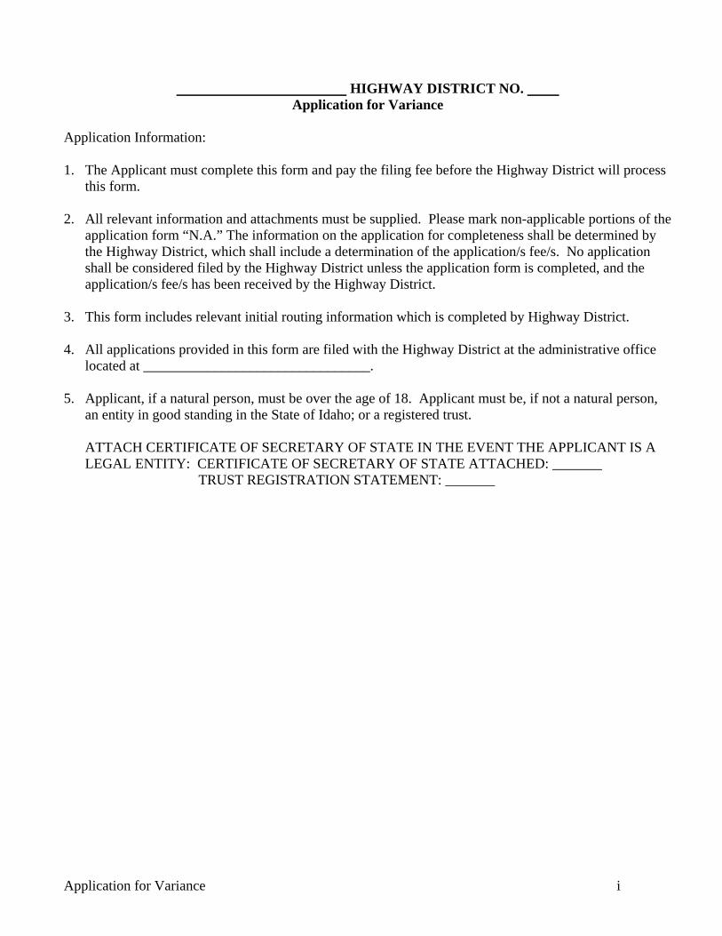
Application for Variance i
HIGHWAY DISTRICT NO.
Application for Variance Application Information: 1. The Applicant must complete this form and pay the filing fee before the Highway District will process
this form. 2. All relevant information and attachments must be supplied. Please mark non-applicable portions of the
application form “N.A.” The information on the application for completeness shall be determined by the Highway District, which shall include a determination of the application/s fee/s. No application shall be considered filed by the Highway District unless the application form is completed, and the application/s fee/s has been received by the Highway District.
3. This form includes relevant initial routing information which is completed by Highway District. 4. All applications provided in this form are filed with the Highway District at the administrative office
located at ________________________________. 5. Applicant, if a natural person, must be over the age of 18. Applicant must be, if not a natural person,
an entity in good standing in the State of Idaho; or a registered trust. ATTACH CERTIFICATE OF SECRETARY OF STATE IN THE EVENT THE APPLICANT IS A
LEGAL ENTITY: CERTIFICATE OF SECRETARY OF STATE ATTACHED: _______ TRUST REGISTRATION STATEMENT: _______

Application for Variance 1
Application for Variance
To: Director and Commissioners Highway District No. Applicant: Date: Address: Phone: Information to Applicant: In accordance with Section 2140.010 of the Highway Standards and Development Procedures for the Canyon County Highway Districts, the same provides: Purpose: The District may grant variances in order to prevent or to lessen such practical difficulties and unnecessary physical hardships as would result from a literal interpretation and enforcement in certain of the regulations prescribed by these Standards.
A variance shall not be considered a right or special privilege, but may be granted to an applicant only upon showing 1) undue hardship because of special characteristics applicable to the site, and 2) the variance is not in conflict with public interest. Hardships must result from special site characteristics, from geographic, topographic or other physical conditions, or from population densities, existing street locations or traffic conditions.
The purpose of a variance is to provide fair treatment and to see that individuals are not penalized because of site characteristics beyond their control. In accordance with Section 2140.030 of the Highway Standards and Development Procedures for the Canyon County Highway Districts, the same provides: Duration of Approval: The use or construction permitted under the terms of any variance shall be commenced within a six (6) month period. If such use or construction has not commenced within such time period, the variance shall no longer be valid. Prior to the expiration of the six (6) month period, the District, upon request of the applicant, may extend the variance for up to an additional six (6) months from the original date of approval. No additional extensions will be allowed. APPLICATION INFORMATION: Description of Right of Way which is subject to the requested variance [Use this space or attach the specific description of subject Right of Way]: Identify the Section in Highway Standards and Development Procedures from which the applicant seeks a variance [Identify the section number and standard in this space.]: Description of requested variance [Use this space or attach a narrative which includes a complete description of proposed variance]:

Application for Variance 2
State what undue hardship will result if the application is not granted because of the following: What are the special characteristics applicable to the site?
Why the granting of the variance will not be detrimental to the public health, safety or welfare or be materially injurious to properties or improvements in the vicinity? Why the literal interpretation and enforcement of the Highway Standard and Development Procedures would result in practical difficulty or unnecessary physical hardship inconsistent with the objectives of those standards and procedures? What are the extraordinary site characteristics applicable to the property involved or to the intended use of the property which do not apply generally to other properties?
Why would a literal interpretation and enforcement of the standards deprive the applicant of privileges enjoyed by the owners of other properties? Why the granting of the requested variance will not constitute a grant of special privilege inconsistent with the limitations on other properties? I do hereby certify to the Commissioners of the HIGHWAY DISTRICT NO. that I am the applicant or a duly authorized agent for the applicant and that the statements and representations here in are true and correct. This day of , 20 .
Applicant’s Signature

Application for Variance 3
THIS PAGE OF FORM FOR HIGHWAY DISTRICT USE ONLY HIGHWAY DISTRICT ACTIONS: Date received: _________________ Filing Fee: ________/ Paid _________ [Highway District Secretary to initial and date fee paid] Director or designee recommendation to Highway District Commissioners: Reviewed by Director or designee: ________ Denial Approval Approval Subject to Conditions Recommended Wording for order granting variance including recommended conditions: Basis for recommendation: Applicant notified of meeting of Highway District Commissioners when matter to be considered: Notification Sent: [date] by: Applicant Appeared: Did Not Appear: _____ Action of Board of Highway District Commissioners: Denial Approval Approval Subject to Conditions Conditions: Basis for Decision: In the event the Application is approved a PERMIT/LICENSE FOR THE USE OF RIGHT-OF-WAY FOR Approved purposes to be drafted, approved and entered into by the applicant and the Commissioners. Dated: _____________ Signed __________________________________ Chairman Original Permit/License Agreement prepared and signed by Applicant and Approved by Board of Commissioners: _______________ [Initialed by Highway District when completed] Original Permit/License together with this Applications form is retained in the official Records of the Highway District and a copy provided to applicant and anyone demanding notice of the decisions. Signed:
Highway District

Plan Review Checklist – Improvement Plans Page 1 of 4
PLAN REVIEW CHECKLIST IMPROVEMENT PLANS
Subdivision: Date: Project Location: Developer: Phone: Fax: Engineer: Phone: Fax: Reference the Highway Standards and Development Procedures for the Canyon County Highway Districts when completing development plans and this checklist.
INCLUDED NOT
APPLICABLE SUBMITTAL ITEM
PLAN NOTES
All work shall be completed in accordance with the Idaho Standards for Public Works Construction (latest edition), the Highway Standards and Development Procedures for the Canyon County Highway Districts and the Project Specifications.
All Contractors, Sub-Contractors and Utility Contractors shall attend a pre-construction conference a minimum of two (2) days prior to commencing any construction on the project.
Only plan sets stamped “Approved for Construction” and signed by the Engineer shall be used for Project construction. Use of plans not stamped “Approved for Construction” shall be grounds for the issuance of a stop work order.
All materials furnished on or for the Project shall meet the minimum requirements of the approving agency or as set forth in the Project plans and specifications, whichever is more restrictive. Contractor shall furnish proof that all materials meet the requirements at the request of the Owner or Engineer.
The Contractor shall be responsible for providing and paying for all costs associated with all testing required by the Project Specifications. All tests shall be performed by a certified testing laboratory and certified test results shall be submitted to the Owner’s Engineer. Work performed without certified test results shall not be accepted.
Plant Mix Pavement shall be Class _____ with a nominal maximum aggregate size of _____. PG _____-_____ (Performance Graded Asphalt Binder) shall be used. A minimum of 0.5% Anti-Stripping additive is specified.
Profile the surface the following roadways in accordance with Idaho T-140: _________
SURVEY
A minimum of two Section/Quarter corners are referenced
Vertical control tied to NAVD 88
Control monuments set within development

Plan Review Checklist – Improvement Plans Page 2 of 4
INCLUDED NOT
APPLICABLE SUBMITTAL ITEM
RIGHT-OF-WAY
Roadway right-of-way widths meet standards
Cul-de-sacs have the required minimum right-of-way
Intersection of right-of-way lines have minimum required radii
All obstructions and right-of-way encroachments are shown to be removed
HORIZONTAL AND VERTICAL ALIGNMENT
Horizontal alignment meets AASHTO standards
Minimum and maximum vertical grades meet the standards
Vertical curves are included for all grade breaks in excess of one percent
Minimum tangent lengths between curves are met
ROADWAY CROSS SECTION
Roadway widths (travel lanes, shoulders, foreslopes, ditches, back slopes, etc.) meet standards
Foreslopes, back slopes and fill slopes meet the established standard and are shown on the plans
Curb and Gutter section is shown where required or approved
Roadside grading and obstructions meet the AASHTO Roadside Design Guide or appropriate guardrail is shown
Pavement, base and sub-base thickness are shown in accordance with the standard or the approved section thickness based on a materials report and section calculations
Base and sub-base aggregate size is called out on the typical roadway section
Asphalt tack coat material and application rate is indicated on the plans
The limits of pavement repair for existing roadways extends to the lane line or centerline
INTERSECTIONS AND APPROACHES
Roadway intersections meet the minimum spacing requirements
Private and commercial approaches meet the minimum spacing requirements with no new approaches to arterial and major collector roadways
Curbed approach show for all accesses serving primarily truck traffic
Mailbox and approach widening length, width and taper are called out on the plans

Plan Review Checklist – Improvement Plans Page 3 of 4
INCLUDED NOT
APPLICABLE SUBMITTAL ITEM
EARTHWORK
A soils report documenting the site soil and groundwater conditions is included with the preliminary plat
A mass excavation and grading plan is included if required by the District
Clearing and seeding limits are shown on the plans
TRENCHING
Utilities are shown in the appropriate corridor, including private utilities in an easement outside the right-of-way
Utility installation in roadways with pavement less than five years old are show as borings
WATER, SEWER AND IRRIGATION
The city or irrigation district has reviewed and approved the plans for their facilities
A copy of the agency conditions and approval has been provided to the District
Valves and manholes are not located within the wheel paths
Irrigation facilities are located outside the right-of-way
Irrigation crossings include cleanout boxes on each side of the right-of-way
Information necessary to complete the appropriate right-of-way use agreements is included
DRAINAGE
Drainage calculations are stamped by an Idaho Registered Professional Engineer and provided with the submittal
All calculations are included with the submittal including time of concentration, peak runoff, runoff volume, conveyance system capacity, infiltration rates, discharge rates, etc.
Culverts are sized appropriately, are of an approved material, include aprons and have adequate cover
Borrow ditches meet the depth standards, including freeboard, and have adequate erosion protection where flow velocities are greater than two feet per second
If subsurface stormwater disposal systems are proposed, documentation that there is no feasible alternative is provided and the system meets the minimum established criteria
Detention and Retention facilities meet the minimum established criteria
Maintenance of stormwater facilities outside the public right-of-way is shown to be the responsibility of the property owner or homeowner’s association

Plan Review Checklist – Improvement Plans Page 4 of 4
INCLUDED NOT
APPLICABLE SUBMITTAL ITEM
STRUCTURES
Bridges meet minimum load requirements
Bridge width meets standards
Bridge clearance above waterways and roadways meet minimum standards
Retaining walls are shown where required
Appropriate materials reports are included for all structure designs
SIGNING AND PAVEMENT MARKINGS
All permanent signing meets the requirements of the MUTCD
A construction traffic control plan meeting the requirements of the MUTCD is included
Pavement markings meeting the MUTCD are shown where required by District standard
TRAFFIC IMPACT STUDIES
Mitigation measures identified in the traffic impact study have been included

Plan Review Checklist – Final Plat Page 1 of 2
PLAN REVIEW CHECKLIST FINAL PLAT
Subdivision: Date: Project Location: Developer: Phone: Fax: Engineer: Phone: Fax: Reference the Highway Standards and Development Procedures for the Canyon County Highway Districts when completing the Final Plat and this checklist.
INCLUDED NOT
APPLICABLE SUBMITTAL ITEM
PLAT NOTES (DEDICATION AND ACCEPTANCE)
Plats with only public road right(s)-of-way dedication(s):
_________ Highway District No. __ does hereby accept this plat, and the dedicated public streets, highways and rights-of-way as are depicted on this plat, in accordance with the provisions of I.C. § 50-1312.
Plats with private roads and public road right(s)-of-way dedication(s):
_________ Highway District No. __ does hereby accept this plat, and the dedicated public streets, highways and rights-of-way as are depicted on this plat, in accordance with the provisions of I.C. § 50-1312. Private streets depicted on this plat are not maintained by or under the jurisdiction of the Highway District. There is no legal obligation or assurances that the private streets will be accepted as public streets in the future.
Plats with private roads and no public road right(s)-of-way dedication(s):
_________ Highway District No. __ does hereby accept this plat in accordance with the provisions of I.C. § 50-1312. Private streets depicted on this plat are not maintained by or under the jurisdiction of the Highway District. There is no legal obligation or assurances that the private streets will be accepted as public streets in the future.
Signature and date line for District Chairman
RIGHT-OF-WAY
Roadway and cul-de-sac right-of-way meet standards
Out parcels and associated right-of-way dedication are properly addressed
Intersection of right-of-way lines have minimum required radii
Sufficient right-of-way is provided for extreme cut and fill locations
Stub streets are included as required by the District
Utility, drainage and other required easements are shown
Roadway alignment (curve radii, tangent lengths) meet standards

Plan Review Checklist – Final Plat Page 2 of 2
INCLUDED NOT
APPLICABLE SUBMITTAL ITEM
INTERSECTIONS AND APPROACHES
Roadway intersections meet the minimum spacing requirements
Access to adjacent properties is available with no landlocked or intervening strip parcels
Note on plat regarding no direct access to adjacent collector and arterial roadways
MISCELLANEOUS
Note on the face of the plat for homeowner’s association or property owner maintenance requirements - The Homeowner’s Association or adjacent property owner is responsible for maintaining any and all amenities (lawns, sprinklers, sidewalks, landscaping, etc.) approved by the District to be within the public right-of-way
Note on the face of the plat for storm drainage facilities maintenance - The Homeowner’s Association, underlying property owner or adjacent property owner is responsible for all storm drainage facilities outside the public right-of-way, including all routine and heavy maintenance
Setback waivers (if applied for) are approved by the District and a note containing language approved by the District is included on the plat

Plan Review Checklist – Conditional Use, Rezone, Preliminary Plat Page 1 of 2
PLAN REVIEW CHECKLIST CONDITIONAL USE, REZONE, PRELIMINARY PLAT
Subdivision: Date: Project Location: Developer: Phone: Fax: Engineer: Phone: Fax: Reference the Highway Standards and Development Procedures for the Canyon County Highway Districts when completing the Improvement Plans, Preliminary Plat and this checklist.
INCLUDED NOT
APPLICABLE SUBMITTAL ITEM
RIGHT-OF-WAY
Roadway and cul-de-sac right-of-way meet standards
All obstructions and right-of-way encroachments are shown to be removed
Out parcels and associated right-of-way dedication are properly addressed
Intersection of right-of-way lines have minimum required radii
Sufficient right-of-way is provided for extreme cut and fill locations
Stub streets are included as required by the District
Utility, drainage and other required easements are shown
Parallel frontage roads are included where required by the District adjacent to collector and arterial roadways
Roadway alignment (curve radii, tangent lengths) meet standards
INTERSECTIONS AND APPROACHES
Roadway intersections and approaches meet the minimum spacing requirements
Access to adjacent properties is available with no landlocked or intervening strip parcels
Approaches and intersections have adequate sight distance
Turn lane requirements have been analyzed
Multiple access points to a single parcel have been pre-approved and meet the applicable spacing requirements
Commercial approaches and approaches serving three or more parcels are paved
No direct access to adjacent collector and arterial roadways

Plan Review Checklist – Conditional Use, Rezone, Preliminary Plat Page 2 of 2
INCLUDED NOT
APPLICABLE SUBMITTAL ITEM
ROADWAY
Roadway design meets District and AASHTO standards including but not limited to intersection geometry, horizontal alignment, profile, cross section and roadside grading
Special considerations (i.e. curb and gutter) are included for development within the area of city impact
The limits of pavement repair for existing roadways extends to the lane line or centerline
TRAFFIC IMPACT STUDIES
A traffic impact study is included based on the established criteria or requirement of the District
Parameters and requirements of the traffic impact study have been discussed with the District
Traffic impact mitigation measures are identified
The traffic impact study is stamped by an Idaho Registered Professional Engineer
DRAINAGE
An area outside the public right-of-way and within an easement is provided for storm drainage disposal facilities
The Homeowner’s Association, underlying property owner or adjacent property owner is responsible for all storm drainage facilities outside the public right-of-way, including all routine and heavy maintenance


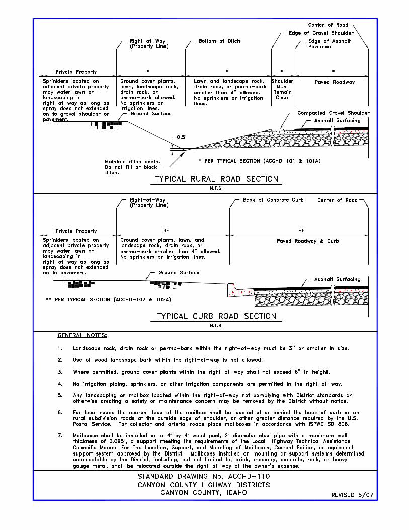
” ” ””


