HIGHWAY EMBANKMENT CONSTRUCTION OVER SOFT...
22
HIGHWAY EMBANKMENT CONSTRUCTION OVER SOFT SOILS IN THE LOWER MAINLAND OF BRITISH COLUMBIA C.N.Weech, M.A.Sc., P.Eng., Golder Associates Ltd. D.R. Lister, M.Sc., P.Eng., Golder Associates Ltd. Paper prepared for presentation at the Session entitled: “Slope and Embankment Engineering for Changing Environments” at the 2009 Annual Conference of the Transportation Association of Canada Vancouver, British Columbia
-
Upload
truonghanh -
Category
Documents
-
view
216 -
download
1
Transcript of HIGHWAY EMBANKMENT CONSTRUCTION OVER SOFT...

HIGHWAY EMBANKMENT CONSTRUCTION OVER SOFT SOILS IN THE LOWER MAINLAND OF BRITISH COLUMBIA
C.N.Weech, M.A.Sc., P.Eng., Golder Associates Ltd. D.R. Lister, M.Sc., P.Eng., Golder Associates Ltd.
Paper prepared for presentation
at the Session entitled:
“Slope and Embankment Engineering for Changing Environments”
at the 2009 Annual Conference of the Transportation Association of Canada
Vancouver, British Columbia

1
HIGHWAY EMBANKMENT CONSTRUCTION OVER SOFT SOILS IN THE LOWER MAINLAND OF BRITISH COLUMBIA C.N.Weech, M.A.Sc., P.Eng. and D.R. Lister, M.Sc., P.Eng., Golder Associates Ltd. Abstract This paper describes the successful construction of new highway embankments over soft soils alongside existing high-traffic volume highways in the Greater Vancouver area of British Columbia. Highway 10 and Highway 15 intersect at Cloverdale in the City of Surrey. Reconstruction and upgrading of 23 km of these two highways have recently been completed as part of the Federal-Provincial Border Infrastructure Program. About 17 km of this upgrading is located in the lowland area of the Nicomekl and Serpentine River floodplains which are underlain by soft and compressible fine-grained and organic soils. In the past, dyke and other embankment failures have been common in the area due to the soft soil conditions. The two projects consisted of highway widening from two lanes to four, construction of over 12 km of new embankment ranging in thickness from 1.5 m to 7.0 m, construction of nine new bridges, relocation of 2 km of railway and 1.2 km of water main, placement of embankment fills over existing sewer, water and gas utilities, and agricultural drainage improvements. Design and construction of the embankments involved: staged preload construction with surcharging to reduce post construction settlements, installation of wick drains and use of lightweight fill materials to reduce the construction time period, and geogrid-reinforced concrete block walls to retain the preload fills. The projects were divided into work areas for the purposes of preload design and construction management. During construction, fill placement was monitored in each work area using a combination of surface and deep settlement gauges, standpipe and pneumatic piezometers, and inclinometers. Instrumentation was monitored on a frequent basis to provide data that allowed project geotechnical engineers to provide approval to allow each stage of preload fill placement to proceed in each work area. This careful approach to embankment construction on the soft soils was very successful as there were no soil failures on the project resulting from the embankment construction. The project was completed on schedule. The paper describes the soil conditions in the area, and the geotechnical challenges to embankment construction posed by these conditions. The embankment design features, staged preload construction methodology, and examples of preload monitoring results are presented.
2
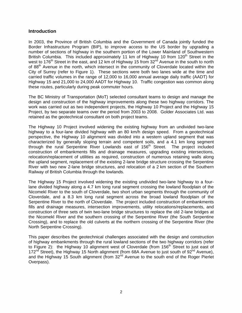
Introduction In 2003, the Province of British Columbia and the Government of Canada jointly funded the Border Infrastructure Program (BIP), to improve access to the US border by upgrading a number of sections of highway in the southern portion of the Lower Mainland of Southwestern British Columbia. This included approximately 11 km of Highway 10 from 120th Street in the west to 176th Street in the east, and 12 km of Highway 15 from 32nd Avenue in the south to north of 88th Avenue in the north, which intersect in the community of Cloverdale located within the City of Surrey (refer to Figure 1). These sections were both two lanes wide at the time and carried traffic volumes in the range of 12,000 to 16,000 annual average daily traffic (AADT) for Highway 15 and 21,000 to 24,000 AADT for Highway 10. Traffic congestion was common along these routes, particularly during peak commuter hours. The BC Ministry of Transportation (MoT) selected consultant teams to design and manage the design and construction of the highway improvements along these two highway corridors. The work was carried out as two independent projects, the Highway 10 Project and the Highway 15 Project, by two separate teams over the period from 2003 to 2008. Golder Associates Ltd. was retained as the geotechnical consultant on both project teams. The Highway 10 Project involved widening the existing highway from an undivided two-lane highway to a four-lane divided highway with an 80 km/h design speed. From a geotechnical perspective, the Highway 10 alignment was divided into a western upland segment that was characterized by generally sloping terrain and competent soils, and a 4.1 km long segment through the rural Serpentine River Lowlands east of 156th Street. The project included construction of embankments fills and drainage measures, upgrading existing intersections, relocation/replacement of utilities as required, construction of numerous retaining walls along the upland segment, replacement of the existing 2-lane bridge structure crossing the Serpentine River with two new 2-lane bridge structures, and relocation of a 2 km section of the Southern Railway of British Columbia through the lowlands. The Highway 15 Project involved widening the existing undivided two-lane highway to a four-lane divided highway along a 4.7 km long rural segment crossing the lowland floodplain of the Nicomekl River to the south of Cloverdale, two short urban segments through the community of Cloverdale, and a 8.3 km long rural segment across the broad lowland floodplain of the Serpentine River to the north of Cloverdale. The project included construction of embankments fills and drainage measures, intersection improvements, utility relocations/replacements, and construction of three sets of twin two-lane bridge structures to replace the old 2-lane bridges at the Nicomekl River and the southern crossing of the Serpentine River (the South Serpentine Crossing), and to replace the old culverts at the northern crossing of the Serpentine River (the North Serpentine Crossing). This paper describes the geotechnical challenges associated with the design and construction of highway embankments through the rural lowland sections of the two highway corridors (refer to Figure 2): the Highway 10 alignment west of Cloverdale (from 156th Street to just east of 172nd Street), the Highway 15 North alignment (from 68A Avenue to just south of 92nd Avenue), and the Highway 15 South alignment (from 32nd Avenue to the south end of the Roger Pierlet Overpass).

3
Soil Conditions The ground surface on the lowland floodplains of the Serpentine and the Nicomekl Rivers (corresponding to the grey-shaded area on Figure 2) is typically around 0 to 2 metres Geodetic elevation. These lowlands are underlain by thick sequences of moderately to highly compressible fine-grained sediments with localized organic soils and peat deposits of variable thickness. Typical soil conditions (based on geotechnical investigations on the north side of the Hwy 15 North Serpentine Crossing) are presented on Figure 3. The following lithostratigraphic soil units (LSU), in order of increasing depth, are generally encountered along the lowland segments of the highway alignments: Highly organic deposits of fibrous to amorphous peat to organic silts, which are inferred to
be bog and shallow lake deposits belonging to the Salish Sediments (LSU), are encountered at surface or under surficial fill materials, generally within 1 to 2 km from the upland slopes. The thicker peat deposits, which were encountered to depths of up to 4.6 m below ground surface at test hole locations, are generally limited to areas near the peripheries of the lowlands. Measured water contents in the peat deposits were typically in the range of 300% to 800%, which is indicative of very high compressibility. The amorphous peat and organic silts are also prone to large lateral deformations in response to vertical loading.
Soft to very soft, clayey silt to silty clay, with minor sand and organic contents, which are inferred to be post-glacial overbank and deltaic deposits belonging to the Fraser River Sediments (LSU), are encountered at surface or underlying Salish organic sediments and extend to depths of up to 15 m below ground surface. These sediments are predominantly fine-grained in composition, but contain thin interbeds of silt/sand mixtures in some areas, as well as occasional thicker seams of fine to medium sand from distributary channel infilling (encountered at the Highway 10 Serpentine Crossing and at the Highway 15 South Serpentine Crossing). Peak undrained shear strengths measured by field vanes and cone penetration tests (CPT’s) are typically in the range of 10 to 20 kPa in this deposit, but strengths of less than 10 kPa were measured locally. These soils are highly sensitive to strength loss when disturbed (remoulded shear strengths are generally only 1 to 3 kPa). These fine-grained sediments exhibit low to medium plasticity, and are moderately compressible and lightly overconsolidated.
Thick deposits of silty clay to clay, with minor sand and stony materials, which are inferred to
be marine and glaciomarine deposits belonging to the Capilano Sediments (LSU), are encountered underlying Fraser River Sediments and/or Salish organic deposits within the lowlands. These sediments are also encountered at ground surface or under surficial fill materials in the slightly elevated Cloverdale urban area and at the base of the upland slopes (refer to the light blue-shaded area on Figure 2). These fine-grained sediments generally exhibit medium to high plasticity. Below an upper stiff to very stiff, over consolidated crust, which tends to be less than 2 m thick, these soils are moderately to highly compressible and close to normally consolidated, and the strength and stiffness tends to increase with depth. In the lowlands, the bottom of this deposit was encountered at Geodetic elevations of approximately -53 to -58 metres at the Hwy 10 Serpentine River Crossing, -63.7 m at the Hwy 15 North Serpentine Crossing, and -71.4 m at the Hwy 15 Nicomekl River Crossing. The bottom of this deposit was not encountered at the deep borehole at the Hwy 15 South Serpentine Crossing which was terminated at a depth of 95 m below ground surface.

4
Generally dense to very dense sand/silt/gravel mixtures, with cobbles, which are inferred to be deposits of the glacial Vashon Drift (LSU), are encountered at depth under the Capilano marine/glaciomarine sediments in the lowlands.
Soft Soil Response to Embankment Loading The increase in stresses within the foundation soils, which is induced by the weight of fill materials, causes an initial increase in the pore water pressure within the fine-grained soils, which tend to have naturally high water contents. In fine-grained soils, particularly those with significant clay contents, the dissipation of the excess pore pressures induced by fill placement is slow due to the low permeability of these materials. Consequently, fill placement using conventional construction methods tends to cause cumulative increases in pore pressure, and the response of the fine-grained soils is described as being effectively “undrained”. In this state, the saturated soils undergo constant-volume deformations in a manner similar to that of a viscous fluid, compressing vertically under the weight of the overlying fills and expanding laterally toward zones of lower confining pressure. In embankment construction, the width of the fill is generally limited relative to the length, so undrained deformations result in lateral displacement of the foundation soils toward the zone of soil under the toe of the embankment where both vertical and horizontal confining stresses are lower. At shallow depths beyond the toe of the embankment, the vertical confining stresses are even lower than the horizontal confining stresses and soil displacements tend to be upward. These internal deformations cause increases in the shear strains and shear stresses within the foundation soils under the embankment and beyond the toe of the embankment. If the shear stresses reach the shear strength of the soil, a failure condition is reached where no additional stresses can be resisted and shear strains can become very large unless displacement is resisted by adjacent soil elements that have not yet failed. When this occurs within soil elements along a continuous path, a slip surface develops which can lead to a collapse of a portion of the embankment if the slip surface “daylights”. Any reduction in confining stress near the toe of the embankment, such as from a channel aligned parallel to the embankment, reduces the available resistance that can be mobilized, and could allow a potential slip surface to daylight along a shorter path. Embankment failures do not necessarily occur immediately after load placement, but can take several hours or even days due to a phenomenon known as “progressive failure”. This involves stress transfer from zones that have failed to zones that have not yet failed as a result of a process called “strain softening” which can occur with additional straining after a soil element has yielded. In normally consolidated and lightly over-consolidated fine-grained soils, and particularly in sensitive fine-grained soils such as those encountered in the Highway 10 and Highway 15 project areas, additional positive pore pressures develop in response to accumulating shear strain. These shear-induced pore pressures can become significant as the soil begins to yield, and the increase in excess pore pressures with the onset of failure causes a reduction in the shear strength of the soil (referred to as “post-peak” strength loss). The loss in strength within failed zones of soils means that the shear stress that was being resisted by the failed soil elements must be transferred to adjacent soil elements that have remaining capacity, which can induce failure within those elements as well. As the excess pore pressures generated by fill placement dissipate, the foundation soils consolidate under the embankment load, resulting in a decrease in the volume of the foundation soils, and further settlement of the embankment fills. This process is referred to as “primary

5
consolidation”. The rate of primary consolidation is controlled by the coefficient of consolidation of the soil (a function of soil permeability and compressibility), by the pore water pressure gradients established within the soil by the embankment loading, and by the distance to drainage boundaries. The rate of consolidation generally slows down with increasing time in a logarithmic manner. Consequently, in thick deposits of predominantly clayey soils, where natural drainage boundaries may be limited to just the ground surface, the time required for full dissipation of excess pore pressures induced by embankment construction can take decades. The compression magnitude due to primary consolidation depends on the compressibility of the soil, on the magnitude of effective stress achieved under the weight of the embankment fills (which increases gradually as the excess pore pressures dissipate) relative to the initial effective stress state, and on the yield stress (the maximum past internal effective stress) of the soil. The compressibility of the soil tends to increase with increasing natural water content, which also tends to increase with increasing clay content and increasing organic content; in general, clays are more compressible than silts, and peat is significantly more compressible than clay. Once the effective stress in the compressible soil reaches its yield stress (commonly referred to as the “preconsolidation pressure”), the compressibility of the soil under further increments in stress typically increases to five to ten times its compressibility at stresses below the yield stress. Even after the excess pore pressures have completely dissipated, compression of the loaded soil continues, albeit at a very slow rate, due to a process commonly referred to as “secondary compression”. Where primary consolidation is very slow, as in thick clay deposits, the magnitude of secondary compression is generally negligible compared to that of primary consolidation. In peat deposits, where primary consolidation occurs relatively quickly, the magnitude of secondary compression can be significant and can be greater than the magnitude of primary consolidation. Design Requirements The widening of Highway 10 and Highway 15 through the lowland floodplains required grade
raises that were typically in the range of 1.2 to 1.5 m above the adjacent field level along the Highway 10 alignment, and typically in the range of 0.8 m to 2.2 m above the adjacent field level along the Highway 15 alignment.
At the river crossings, the grade of the original two-lane roadways had to be raised by about 2 to 3 metres in order to accommodate the depth of the bridge decks and girders along with a minimum soffit clearance above design flood level. This meant that the required grade raises were generally in the range of 3 to 5 metres above the original ground surface adjacent to the original highway embankments. The high fills required for the bridge approaches were expected to cause significant settlements and to pose significant risks to the stability of the banks of the salmon-bearing Serpentine and Nicomekl Rivers.
Roadway widening involved in-filling of existing drainage ditches, so new drainage ditches
along the toe of the widened roadway embankments had to be constructed as part of the projects. In some areas the ditches had to be constructed to an agricultural standard that required invert depths approximately 2 m below the adjacent field grade. Since much of the land adjacent to the highway widening is being used for crops, drainage had to be maintained throughout construction. The depth and timing of new ditch excavations relative to fill placement was a significant design issue.

6
Settlement of adjacent utilities lines, including gas mains, water lines and sewers, due to the embankment fills had to be assessed and mitigation measures implemented.
Preliminary design started in September 2003 and construction had to be completed by
September 2008. Traffic flow had to be maintained on the original two lane highways throughout construction. This dictated that new two lane bridges and approach fills on the widened side of the highway had to be completed at the river crossings, and detours onto the new bridge structures constructed, before the original highway grades could be raised and the original bridges replaced with new bridge structures. Thus, interim completion milestones were established which dictated the amount of time available to construct the embankment fills and allow settlement to occur prior to final grading and paving.
Project-Specific Geotechnical Design Challenges The following characteristics of the soft soils along the Highway 10 and Highway 15 alignments through the lowland floodplains presented significant geotechnical challenges to the design and construction of the embankments: The thickness of the compressible sediments is extensive (in excess of 50 m over much of
the lowland areas), and the fine-grained sediments have a low permeability and there is a scarcity of natural drainage layers within the deposits over much of the area. Consequently, significant long-term settlement magnitudes can be expected if embankments are constructed using mineral fills, and only a portion of this settlement can be practically removed within the available construction period.
Fibrous to amorphous (fine-grained) peat and organic fine-grained soil deposits are
encountered at or near surface along segments of the highway alignments. Where present, the organic deposits can be expected to cause embankment settlements that are much higher than in areas without organic soils. Furthermore, the variable thickness and highly variable compressibility of these organic soils can cause significant differential settlements over relatively short distances.
The clayey silt to silty clay within 5 to 10 m depth below the original ground surface is soft to
very soft, with undrained shear strengths typically in the range of 10 to 20 kPa, which are among the softest deposits in the Lower Mainland. These sediments are also highly sensitive to disturbance-induced strength loss, and remoulded shear strengths are generally only 1 to 3 kPa.
The amorphous peat and organic fine-grained soils typically have very low shear stiffness
and tend to deform initially in an undrained manner when subjected to normal fill placement rates. The resulting lateral deformations within the amorphous peat layers can be significant, which can induce large strains within the underlying sensitive silt/clay deposits, leading to shear failures and strain-softening in the sensitive fine-grained soils.
Numerous collapses of earth fills constructed by others prior to and during the course of the Highway 10 and 15 projects have occurred in the lowland areas adjacent to Highways 10 and 15. The consequences of such failures ranged from temporary disruption of drainage ditches, to impacts to the Serpentine River, to damage to adjacent roads, overhead telephone and hydro lines, and the BC Railway lines to the Deltaport terminal, to severe damage to the foundations of the Highway 15 overpass over the BC Railway line.

7
In addition to the direct costs of repairs, a collapse of a portion of the embankments could cause injuries or environmental damage. A failure would also have significant impacts to the construction schedule and to the long-term performance of the completed highway embankment. This is because strain-softening of the foundation soils during an embankment collapse can reduce their strength to remoulded values which would make immediate reconstruction of the failed portion of the embankments using mineral fills nearly impossible. Significant time would be required for dissipation of the excess pore pressures generated during the failure, which would result in a recovery of some of their former strength. However, even after sufficient time has elapsed, the strength of the foundation soils might only be one half to one third of the original limited undrained strength of the soil before the failure. Consequently, embankment reconstruction would have to be very slow, or the mineral fills would have to be replaced with lightweight fill materials. Design Solutions During preliminary design, the following construction techniques were identified to mitigate or manage settlement impacts and stability risks: Preloading the foundation soils by construction of mineral fills to heights in excess of the
required design grade (referred to as surcharging), to induce settlement prior to final grading and paving.
Relocated drainage ditches adjacent to the toe of the preload fills were generally limited to
depths of approximately 0.5 to 0.6 metres for the duration of the preload construction and surcharging period. Following removal of the surcharge portion of the preload fill, the temporary ditches were deepened and widened to the ultimate design cross-section.
Installation of vertical wick drains in selected areas where fills in excess of 3 m thickness
were required, in order to accelerate dissipation of excess pore water pressures. This was intended to reduce undrained deformations and the risk of failure of the weak foundation soils under the higher fill loads, and to accelerate consolidation of the foundation soils and the resulting embankment settlements.
Staged fill construction, which involved placing the preload fill was in stages of limited
thickness (typically 0.5 m to 1 m), with time allowed between stages for stabilization of the undrained deformations within the foundation soils. This also allowed some time for the shallow foundation soils to consolidate and strengthen before the next increment in load was applied.
Installation and monitoring of geotechnical instrumentation to measure soil movements and
pore water pressures resulting from preload fill placement. The monitoring data was used during construction to determine when the next stage of fill could be placed in a particular area.
Construction of lightweight fills to complete grade raises where an embankment constructed
entirely of mineral fill would have posed an unacceptable risk of failure (eg. adjacent to the river banks), or where settlement impacts to adjacent facilities from a mineral fill embankment were considered to be unacceptable (eg. at some utility crossings), or where there was insufficient time available for preloading.
8
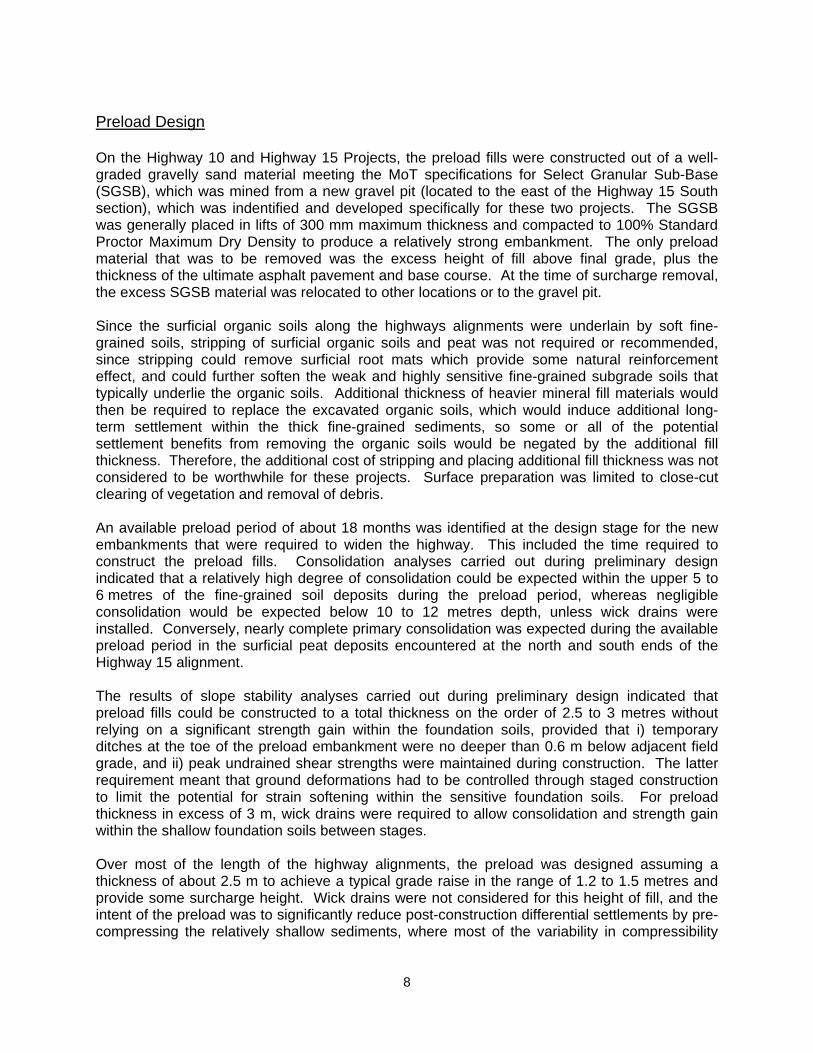
Preload Design On the Highway 10 and Highway 15 Projects, the preload fills were constructed out of a well-graded gravelly sand material meeting the MoT specifications for Select Granular Sub-Base (SGSB), which was mined from a new gravel pit (located to the east of the Highway 15 South section), which was indentified and developed specifically for these two projects. The SGSB was generally placed in lifts of 300 mm maximum thickness and compacted to 100% Standard Proctor Maximum Dry Density to produce a relatively strong embankment. The only preload material that was to be removed was the excess height of fill above final grade, plus the thickness of the ultimate asphalt pavement and base course. At the time of surcharge removal, the excess SGSB material was relocated to other locations or to the gravel pit. Since the surficial organic soils along the highways alignments were underlain by soft fine-grained soils, stripping of surficial organic soils and peat was not required or recommended, since stripping could remove surficial root mats which provide some natural reinforcement effect, and could further soften the weak and highly sensitive fine-grained subgrade soils that typically underlie the organic soils. Additional thickness of heavier mineral fill materials would then be required to replace the excavated organic soils, which would induce additional long-term settlement within the thick fine-grained sediments, so some or all of the potential settlement benefits from removing the organic soils would be negated by the additional fill thickness. Therefore, the additional cost of stripping and placing additional fill thickness was not considered to be worthwhile for these projects. Surface preparation was limited to close-cut clearing of vegetation and removal of debris. An available preload period of about 18 months was identified at the design stage for the new embankments that were required to widen the highway. This included the time required to construct the preload fills. Consolidation analyses carried out during preliminary design indicated that a relatively high degree of consolidation could be expected within the upper 5 to 6 metres of the fine-grained soil deposits during the preload period, whereas negligible consolidation would be expected below 10 to 12 metres depth, unless wick drains were installed. Conversely, nearly complete primary consolidation was expected during the available preload period in the surficial peat deposits encountered at the north and south ends of the Highway 15 alignment. The results of slope stability analyses carried out during preliminary design indicated that preload fills could be constructed to a total thickness on the order of 2.5 to 3 metres without relying on a significant strength gain within the foundation soils, provided that i) temporary ditches at the toe of the preload embankment were no deeper than 0.6 m below adjacent field grade, and ii) peak undrained shear strengths were maintained during construction. The latter requirement meant that ground deformations had to be controlled through staged construction to limit the potential for strain softening within the sensitive foundation soils. For preload thickness in excess of 3 m, wick drains were required to allow consolidation and strength gain within the shallow foundation soils between stages. Over most of the length of the highway alignments, the preload was designed assuming a thickness of about 2.5 m to achieve a typical grade raise in the range of 1.2 to 1.5 metres and provide some surcharge height. Wick drains were not considered for this height of fill, and the intent of the preload was to significantly reduce post-construction differential settlements by pre-compressing the relatively shallow sediments, where most of the variability in compressibility

9
was expected, while conceding that there would still be post-construction settlement from consolidation of the deeper sediments. The available time for staged construction of preload at the river crossings was limited by the need to provide access for the bridge construction contractor by summer of 2005 for the first new Highway 10 bridge and by summer of 2006 for all the first new river bridge Highway 15. Therefore, the design thickness of the preload embankments at the bridge approaches was limited to the required grade raise plus settlement allowance plus a surcharge height that was generally minimal compared to the total thickness of fill placed. Consequently, negligible surcharge effect was expected for the bridge approach fills. At all four river crossings, the grade raises for the new bridge approaches on the widened side of the highways required preload fills to be constructed to a thickness of up to 5 to 6 m, so wick drains were required for stability purposes, and the fill had to be placed in up to six different stages. At the bridge approaches, the depth of the wick drains was generally increased from -10 m elevation at the lower end of the fills to between -15 m and -23 m elevation at the higher end of the fills closer to the river banks. The deeper wicks were intended to reduce long-term settlements under the thicker fills, while the wick drains to -10 m were intended to improve stability during fill placement and to provide a settlement transition between the deeper wick areas and the areas without wick drains. For the Highway 15 bridges, deep wick drains were installed to elevations between about -35 m and -38 m (up to 40 m below ground surface) in order to reduce post-construction settlement of the friction pile-supported bridge abutments through preloading of the deeper soils in which the piles would mobilize load resistance under working stress conditions. A longitudinal profile through the preload for the south approach of the northbound Highway 15 bridge at the North Serpentine Crossing, including the wick drain arrangement, is illustrated on Figure 4. In the embankment areas underlain by significant peat deposits, along Highway 15 between 32nd and 40th Avenues and north of the Serpentine River North Crossing, 4 to 5 metre thick preload embankments were designed and constructed to induce major compression of the peat deposits during the preload period. Since the actual grade raise required in the peat areas were low relative to the thickness of fill placed, the ratio of total fill thickness placed to the permanent fill thickness left after surcharge removal was relatively high. This was intended to reduce long-term settlements, and particularly differential settlements, due to secondary compression, which are normally significant in fills placed over peat deposits. Wick drains were required to construct the fills to this height, but these were generally limited in depth to -10 m elevation since their primary function was to reduce the risk of failures during construction. After wick drain installation, geogrid reinforcement was installed near the base of the embankments constructed on peat to reduce lateral spreading of the embankments through the tensile resistance of the geogrid. This additional lateral constraint in the preload fill reduced the lateral deformations within the peat layer, which in turn reduced the lateral deformations in the top of the underlying sensitive fine-grained soils. At most of the bridge approaches, temporary retaining walls were constructed using interlocking concrete blocks with geogrid-reinforced SGSB backfill, for retention of the preload on the side of the original highway. This allowed the full-height portion of the preload to be located as close as practical to the centerline of the ultimate highway. The depth, spacing, and horizontal extents of the wick drains installed at this location are also shown on the profile and cross-section. All wick drains were installed through Stage 1 of the preload fill (as shown on Figure 4), which provided a working mat for the wick drain installation equipment and provided a permeable layer into which the water from the wick drains could discharge.

10
Lightweight Fills Lightweight fills were required in the following areas: Between the bridge abutments and the full-height preload embankments on the widened
side of the highway, since the preload fills could not be constructed to full height near the river banks due to stability constraints. The thickness of the preload fills that were placed adjacent to the river banks at the Highway 15 river crossings were generally limited to about 2.5 to 3.5 metres, and the full-height preload was setback by some distance, which was assessed for each of the river crossings based on slope stability analyses. The greatest setback (12 m) was required at the Highway 15 North Serpentine Crossing (as shown on the preload profile on Figure 4), whereas no setback was required at the Highway 10 Serpentine River Crossing due to the stronger soils at that site.
For raising the grade of the original 2-lane highways at the bridge crossings, since there was
insufficient time in the construction schedule for preloading of the original highway side after completion of the highway detours onto the preloaded approaches and the new bridges on the widened side of the highway. Raising the original highway grades using mineral fill during or after the new bridges were constructed (i.e. no preloading in advance of bridge construction) would have induced significant vertical and lateral soil movements that could have adversely impacting the new bridges and their piled foundations. Furthermore, placing mineral fills on the original highway would have induced significant post-construction settlement of the completed approaches on the widened side of the highways.
Placement above settlement-sensitive utility lines such as sanitary sewer gravity mains, gas
mains, and water mains. The lightweight fill options that were considered included hogfuel (wood waste consisting primarily of tree bark), Expanded Polystyrene (EPS) blocks, and Lightweight Cellular Concrete (LCC). There is a long history of hogfuel being used successfully as lightweight fill in the Lower Mainland, and this was expected to be the cheapest option of the lightweight fill alternatives. However, the use of hogfuel was not considered suitable for this application because of environmental concerns regarding hogfuel leachate seeping into adjacent fish-bearing rivers and tributary ditches, and the costs associated with providing an appropriate leachate collection system. Furthermore, hogfuel has a low stiffness in compression and would therefore provide low resistance to lateral movement of the bridge abutments under the design seismic loads. EPS is by far the lightest fill option, with densities typically less than 30 kg/m3. This material was used to replace some of the granular fill materials above some of the utility crossings in order to minimize the induced settlements where grade raises were required. This included two sanitary sewer gravity mains at the upgraded intersection of Highway 10 and Highway 15. Due to the relatively high compressibility of this material, a 1.0 m minimum thickness of flexible pavement structure (asphalt + granular base and sub-base courses) above the EPS is required to reduce bearing pressures from wheel loads. This fill material was originally considered for the bridge approaches, but preliminary dynamic analyses of the structural response of the bridges suggested that lateral movements of the bridge abutments under the design seismic loading would be excessive due to the low stiffness of the EPS material.

11
Unlike EPS, LCC has a very high stiffness relative to other fill materials. The 28-day compressive strength of LCC with a cast density of about 500 kg/m3, approximately 1 MPa, and the modulus of elasticity approximately 400 MPa. Therefore, when used as bridge abutment backfill, the LCC was predicted to provide much greater resistance to lateral abutment movements under seismic loading than the EPS alternative. Also, a thinner pavement structure can be used on top of the LCC with no risk of damage from conventional traffic loadings. Consequently, for LCC thicknesses up to about 2.5 m, the total weight of LCC plus pavement structure was predicted to be less than the weight of the equivalent height of EPS plus pavement structure (assuming that a 600 mm thick compacted sub-base would be required for the EPS option, which would not be required for the LCC option). Another advantage of LCC at the Highway 15 bridge crossings was that the LCC can be cast with vertical faces with no requirements for external support once the concrete has cured. This reduced the overall volume of lightweight fill that would have been required if the approach embankments were constructed with side slopes, as would be required for most other lightweight fill materials. Where permanently exposed, the LCC needs to be protected by structural facing elements. Pre-cast concrete panels used in Mechanically Stabilized Earth construction were specified for the facing of the LCC, and the structurally connected to the LCC block via anchors which are cast into the LCC during placement. The ability to construct vertical walls eliminated the need for preloading of the ditches to the west of the existing highway at the North Serpentine Crossing. It was also a particularly important design factor at the South Serpentine Crossing, where long wing walls were required along the sides of the bridge end fills that protruded into the high water portion of the river channel due to the skew angle of the river relative to the highway alignment. Preload Monitoring Instrumentation To monitor the stability and settlement performance of the preload fills, the following types of monitoring instrumentation were installed and monitored throughout the preload period including preload construction: Settlement Gauges (SG’s) consisting of a plywood base plate with steel riser pipes. The
base plate was installed at the original ground surface and surveyed prior to fill placement, and the riser pipes extending above the top of preload and the top of pipe and top of preload were surveyed regularly. The data was used to determine the elevation of the base plate and therefore the top of the original ground surface, from which the preload thickness and preload settlement were computed. The settlement gauges were installed at longitudinal intervals of 50 m or less, and were used to specify and field-mark the fill thickness to be placed during each stage. At some longitudinal positions, a single SG was installed in the middle of the embankment cross-section, and at other longitudinal positions one SG was installed over the ditch infill and another SG was installed at an offset roughly corresponding to the ultimate crest of the preload embankment. A total of approximately 460 SG’s were installed along the three highway alignments.
Inclinometers consisting of plastic pipes that were installed within grouted boreholes that
extended to depths below the anticipated depth of lateral deformations. The inside of the pipes are machined with longitudinal grooves that provide a consistent guide for an inclinometer probe which contains accelerometers that measure the inclination of the pipe in two orthogonal directions. By taking inclination measurements at 0.5 m intervals of depth, a depth profile of horizontal deviation from vertical was determined. Changes in this profile

12
detected from successive readings indicated where horizontal displacement was occurring. From this data, incremental and cumulative displacements were computed at various depths. The inclinometers were typically located approximately 0.5 m beyond the field-side toe of the preload embankment, and were generally spaced longitudinally at roughly 300 m intervals. Inclinometers were also installed between the toe of the preload and the crest of each of the river banks at the bridge crossings. A total of 78 inclinometers were installed.
Pneumatic Piezometers (PP’s), which allowed the pore water pressures in the fine-grained soils to be measured using an external pneumatic pressure gauge. The PP’s used on the Highway 10 and Highway 15 projects were designed with conical tips for push-in installation and were attached to steel riser pipes that extended above the top of the preload. The PP’s were pushed into the fine-grained soils through the bottom of wash rotary boreholes (pushing distances of 1.5 to 3 metres) to ensure intimate contact with the fine-grained soils, and to minimize the potential for contamination of the porous filter element with organic or unsaturated soils. The riser pipes provide a means of pushing the piezometers to the design depth, they protect the pneumatic tubing from being damaged during fill placement, and they allow the elevation of the piezometers tips to be monitored during construction. Clustered groups of two or three PP’s were generally installed to different tip depths in the middle of the embankment cross-section at longitudinally intervals of roughly 300 m (closer spacing’s were used at the bridge approaches). A total of about 135 PP’s were installed.
Standpipe Piezometers (SP’s) installed within the preload fills to measure the groundwater
level within the fill. The SP’s were attached to the riser pipes of the settlement gauges that were installed at the locations of the PP clusters, and the bottom of the filters were installed on top of the SG base plates. A total of about 180 SP’s were installed.
Deep Settlement Gauges (DSG’s) consisting of corrugated plastic pipes outfitted with
magnets located at 1.5 m intervals along the pipe length, which were installed within grouted boreholes that extended to depths in the range of -22 to -43 metres elevation. The depth to each set of magnets were measured periodically using a magnetic probe and the increase in the depth of the magnets relative to the baseline reading indicated the cumulative amount of settlement that had occurred below each set of magnets. The elevation of the bottom of the DSG was monitored by surveying the top of an inner pipe that rests on the bottom of the DSG but is not otherwise connected to the compressible outer casing. This data allowed the trend of compression with time to be determined for selected depth intervals, to determine where in the soil profile compression was occurring and where it was nearing completion. A total of 23 DSG’s were installed.
Preload Construction A key element in the successful construction of mineral fill embankments on the very challenging soft soil conditions in the Lowland areas along the Highway 10 and Highway 15 alignments was the stage approval process that was specified in the preload construction contracts. The contractors were required to divide each of the highway alignments into designated work areas, and no fill placement could proceed within a work area without receiving approval from the MoT contract managers. This approval was provided by the geotechnical engineer based on an assessment of the instrumentation monitoring results, including data from the inclinometers, settlement gauges, and piezometers. The approval included specification of the thickness of the approved stage in a particular area. During the later stages, the thickness

13
of a stage was varied along the highway alignment using the settlement gauges as measuring sticks. The total duration of preload construction depended on a combination of three factors: 1. the time required for the contractor to place each stage of fill in a particular work area
(average time of about 7 to 8 calendar days along Highway 15 South); 2. the time required to monitor the resulting soil deformations and to confirm that they had
slowed adequately to allow the next stage to be placed in that work area; and 3. the time between granting approval to place the next stage in a particular work area and the
contractor starting placement in that work area. The time between completion of fill placement and approval of the next stage of fill along Highway 15 South was generally in the range of 20 to 40 days in the wick drain areas at the Nicomekl River approaches, and generally in the range of 40 to 70 days in the areas without wick drains and in the peat areas (with wick drains). In the areas where wick drains were installed, stages were generally placed up to 1.0 m thick; but in most of the areas without wick drains, stages were limited to 0.6 m maximum thickness after Stage 1, which meant that four stages instead of three were required to complete a total preload thickness in the range of 2.4 to 2.9 metres. The total time required to construct the preload to full height at any particular settlement gauge location along the Highway 15 South alignment is plotted against the total preload height on Figure 5. The time required to construct the preload embankments in the areas without wick drains ranged from 130 days to 240 days and averaged about 205 days for an average preload thickness of 2.6 m. The time required to construct the higher preload embankments in the areas with wick drains included the time required to install the wick drains between Stages 1 and 2. Even including the additional delay due to wick drain installation, the average rate of fill placement at the Nicomekl River approaches was significantly faster than in areas with similar soil conditions without wick drains. In the peat areas, the wick drains (and geogrid reinforcement) allowed embankments to be constructed higher and faster than would have been possible without the wick drains, but the average rate of construction of the embankments in the peat area was still only marginally faster than in the areas with no wick drains and minimal peat thickness. Preload Monitoring Results The vertical and horizontal deformations of the soft foundation soils were monitored using settlement gauges (SG’s) and inclinometers, respectively. An example of the large deformations that were measured within the foundation soils below the preload embankment at Sta. 119+100 (in the peat area north of 88th Avenue), is provided on a cross-section view on Figure 6. This figure shows cumulative preload settlement at two SG locations (SG15-127 and SG15-128) within the embankment and cumulative lateral displacement of the foundation soils below the toe of the embankment at inclinometer INC15-022, as of the final set of readings taken before surcharge removal. The variations in settlement with time at SG15-127 and lateral displacement with logarithm of time at INC15-022, in response to the 5 stages of fill placed at this location, are plotted on Figure 7. Significant increases in the rate of lateral displacement can be seen after placement

14
of each major increment in fill thickness. Across the project area, initial displacement rates measured between the first and second set of inclinometer readings taken after fill placement were typically on the order of 1 to 3 mm/day, although a range of 3 to 6 mm/day was common in peat areas. In some cases, initial displacement rates in excess of 10 mm per day were recorded, and this was considered to be a situation to be avoided due to the possibility of rapid accumulation of strain within the sensitive soils and an associated high risk of failure. After placing each stage, the rate of lateral displacement would slow gradually as pore pressure dissipation occurred. The experience gained during these preload monitoring programs indicated that initial displacement rates following fill placement were generally reasonable if the displacement rate from the previous stage was allowed to slow to around 0.3 mm/day or less. Approval was granted in some cases when the displacement rate was between 0.4 and 0.6 mm/day (due to construction schedule pressures), in most of these cases, the initial rate of displacement following the next stage of fill placement was found to be at such high levels and that extra monitoring was required to confirm that the displacement rates were slowing. The pattern of increase in lateral displacement rate in response to fill placement, followed by a gradual deceleration, is also consistently reflected in the patterns of settlement with logarithm of time measured at the SG locations (see Figure 7). Settlement due to soil consolidation (as a result of pore pressure dissipation) is generally linear with logarithm of time. The typical deceleration of the preload settlements with logarithm of time within the first month or so after fill placement can be attributed to a decrease in the rate of settlement that is due to undrained compression of the fine-grained soils. This type of soil compression was found to be a significant proportion of the total recorded preload settlement, and is one of the reasons why recorded settlements during the preload period were so high on these projects. The variation in cumulative preload settlements and total fill thickness measured at settlement gauge locations along the Highway 10, Highway 15 South and Highway 15 North alignments (as of the end of the preload periods) are plotted with distance on Figures 8a, 8b and 8c, respectively. The total lateral displacement measured in the inclinometers at the toe of the preload are also plotted on these figures. Recorded settlement magnitudes were generally higher in areas higher fill thickness, as shown by the plot of cumulative settlement vs. total fill thickness on Figure 9. Variability in the trend of settlement vs. fill placement can be expected as a result of natural variability in the shear stiffness and compressibility of the foundation soils and in the degree of consolidation achieved during the preload period (which depends on preload duration and subsurface drainage). Despite the expected natural variability, most of the data falls within the band indicated on Figure 9. As was expected, the preload settlements within the peat areas were higher than those measured under similar preload heights at the bridge crossings where no peat was encountered (eg. the approaches to the Hwy 15 Nicomekl and South Serpentine Crossings). In particular, the trend of settlement vs. fill height in the peat area at the north end of the Highway 15 North alignment was significantly greater than in any other areas, with measured settlements of up to 2840 mm under 6.0 m of fill. Conversely, the settlement of the higher fills at the approaches to the Highway 10 Serpentine Crossing were significantly less than was recorded at the other bridge approaches, due to the lower compressibility of the sediments at that site.
Cumulative lateral displacement magnitudes of up to 260 mm were measured at the inclinometer locations in areas without wick drains were fills up to about 3.1 m in thickness were placed. Comparable lateral displacement magnitudes of up to 300 mm were measured in non-peat areas with wick drains where fill thicknesses of up to 5.9 m were placed, which

15
demonstrates the effectiveness of the wick drains at reducing lateral deformations. In the peat areas, lateral displacement magnitudes between 170 mm and 630 mm (generally greater than 300 mm) were measured where fill thicknesses were between 3.3 m and 6.4 m, which demonstrates the particular stability problems that can be encountered building embankments on such soils.
Conclusion This paper documented the design and successful construction of new highway embankments up to 7 m in thickness on extensive deposits of weak and compressible soils in the Serpentine and Nicomekl River Lowlands of Surrey, BC. Through a combination of staged preload construction with selective use of wick drains and lightweight fills, and regular monitoring of preload instrumentation and geotechnical assessment of the monitoring data, the embankments were constructed without a single failure, in an area that is plagued with failures. This allowed the Highway 10 and Highway 15 Projects to be completed on schedule.
Figure 1 - Location of Highway 10 and Highway 15 Projects
Highway 15
Highway 10

16
Figure 2 - Surficial Geology Plan and Location of Rural Lowland Segments of Highways

17
Figure 3 - Typical Subsurface Conditions

18
Figure 4 - Typical Preload Embankment Profile at Bridge Approach
Figure 5 - Total Preload Thickness vs. Total Time to Place Fill (Hwy 15 South)
0
1
2
3
4
5
6
7
0 50 100 150 200 250 300 350 400
To
tal F
ill T
hic
kn
es
s (m
)
Total Time to Place Fill (Days)
Preload Without Wicks
With Wicks (Peat Area)
With Wicks (Bridge Approaches)

19
Figure 6 - Measured Soil Deformations Under Preload Embankment at Sta. 119+100
Figure 7 - Preload Settlement and Lateral Displacement with Time at Sta. 119+100
0.0
0.5
1.0
1.5
2.0
2.5
3.0
3.5
4.0
4.5
5.0
0
200
400
600
800
1000
1200
1400
1600
1800
2000
10 100 1000
Fill Thickness (m
)
Settlement and Lateral D
isplacement (m
m)
Elapsed Time (Days) from Start of Fill Placement
Settlement Gauge: SG15‐127
Inclinometer: INC15‐022
Fill Thickness
Stage 1 (includes
wickdrain installation)
Stage 2a
(geogrid
installation)
Stage 2b
Stage 3
Stage 4Stage 5

20
Figure 8a – Preload Settlements and Lateral Displacements along Hwy 10 Alignment
Figure 8b – Preload Settlements and Lateral Displacements along Hwy 15 South Alignment
0
1
2
3
4
5
6
0
300
600
900
1200
1500
1800
107+
250
107+
500
107+
750
108+
000
108+
250
108+
500
108+
750
109+
000
109+
250
109+
500
109+
750
110+
000
110+
250
110+
500
110+
750
111+
000
Se
ttle
me
nt
an
d L
ate
ral
Dis
pla
ce
me
nt
(mm
)
Chainage (m) along Highway
Cumulative Settlement
Total Lateral Displacement at Preload Toe
Total Fill Thickness
To
tal F
ill T
hic
kn
es
s(m
)
Old McLellanRd
WickDrains
168th Street
172nd Street
156th Street
Serpentine River
160th Street
0
1
2
3
4
5
6
7
0
400
800
1200
1600
2000
2400
2800
100+
000
100+
250
100+
500
100+
750
101+
000
101+
250
101+
500
101+
750
102+
000
102+
250
102+
500
102+
750
103+
000
103+
250
103+
500
103+
750
104+
000
104+
250
104+
500
Se
ttle
me
nt
an
d L
ate
ral
Dis
pla
ce
me
nt
(mm
)
Chainage (m) along Highway
Final Settlement
Total Lateral Displacement at Preload Toe
Total Fill Thickness
To
tal F
ill T
hic
kn
es
s (m
)
32 Avenue
40 Avenue
176 Street
48 Avenue
Nikomekl River
Crossing
Wick Drains
Wick Drains

21
Figure 8c – Preload Settlements and Lateral Displacements along Hwy 15 North Alignment
Figure 9 – Total Settlement vs. Total Fill Thickness
0
1
2
3
4
5
6
7
8
0
400
800
1200
1600
2000
2400
2800
3200
114+
750
115+
000
115+
250
115+
500
115+
750
116+
000
116+
250
116+
500
116+
750
117+
000
117+
250
117+
500
117+
750
118+
000
118+
250
118+
500
118+
750
119+
000
119+
250
119+
500
119+
750
Se
ttle
me
nt a
nd
La
tera
l D
isp
lac
em
en
t (m
m)
Chainage (m) along Highway
Cumulative Settlement
Total Lateral Displacement at Toe of Preload
Total Fill Thickness
To
tal F
ill T
hic
kn
ess
(m)
Fraser H
ighway
WickDrains
Serpentine River
South Crossing
80 Avenue
Wick Drains
Serpentine River
North Crossing
88 Avenue
0
200
400
600
800
1000
1200
1400
1600
1800
2000
2200
2400
2600
2800
3000
0 1 2 3 4 5 6 7 8
To
tal S
ett
lem
en
t (m
m)
Total Fill Thickness (m)
Without Wicks
With Wicks in Peat Area (HWY 15 North)
With Wicks in Peat Area (HWY 15 South)
With Wicks (HWY 15 ‐ South Serpentine Approaches)
With Wicks (HWY 15 ‐ North Serpentine Approaches)
With Wicks (HWY 15 ‐ Nicomekl Approaches)
With Wicks (HWY 10 ‐ Serpentine Approaches)