Highly Scalable Monitoring System on Chip for Multi-Stream ...
8
HAL Id: hal-01535640 https://hal-enpc.archives-ouvertes.fr/hal-01535640 Submitted on 9 Jun 2017 HAL is a multi-disciplinary open access archive for the deposit and dissemination of sci- entific research documents, whether they are pub- lished or not. The documents may come from teaching and research institutions in France or abroad, or from public or private research centers. L’archive ouverte pluridisciplinaire HAL, est destinée au dépôt et à la diffusion de documents scientifiques de niveau recherche, publiés ou non, émanant des établissements d’enseignement et de recherche français ou étrangers, des laboratoires publics ou privés. Highly Scalable Monitoring System on Chip for Multi-Stream Auto-Adaptable Vision System Ali Isavudeen, Nicolas Ngan, Eva Dokladalova, Mohamed Akil To cite this version: Ali Isavudeen, Nicolas Ngan, Eva Dokladalova, Mohamed Akil. Highly Scalable Monitoring Sys- tem on Chip for Multi-Stream Auto-Adaptable Vision System. International Conference on Re- search in Adaptive and Convergent Systems, Sep 2017, Krakow, Poland. pp.Pages 249-254, 10.1145/3129676.3129721. hal-01535640
Transcript of Highly Scalable Monitoring System on Chip for Multi-Stream ...
HAL Id: hal-01535640https://hal-enpc.archives-ouvertes.fr/hal-01535640
Submitted on 9 Jun 2017
HAL is a multi-disciplinary open accessarchive for the deposit and dissemination of sci-entific research documents, whether they are pub-lished or not. The documents may come fromteaching and research institutions in France orabroad, or from public or private research centers.
L’archive ouverte pluridisciplinaire HAL, estdestinée au dépôt et à la diffusion de documentsscientifiques de niveau recherche, publiés ou non,émanant des établissements d’enseignement et derecherche français ou étrangers, des laboratoirespublics ou privés.
Highly Scalable Monitoring System on Chip forMulti-Stream Auto-Adaptable Vision SystemAli Isavudeen, Nicolas Ngan, Eva Dokladalova, Mohamed Akil
To cite this version:Ali Isavudeen, Nicolas Ngan, Eva Dokladalova, Mohamed Akil. Highly Scalable Monitoring Sys-tem on Chip for Multi-Stream Auto-Adaptable Vision System. International Conference on Re-search in Adaptive and Convergent Systems, Sep 2017, Krakow, Poland. pp.Pages 249-254,�10.1145/3129676.3129721�. �hal-01535640�

On-chip Monitoring for Self-Aware Multi-StreamVision System
Ali Isavudeen1,2, Nicolas Ngan1Safran Electronics and DefenseGroupe Safran, Eragny, France
Email: {ali.isavudeen, nicolas.ngan}@safrangroup.com
Eva Dokladalova, Mohamed Akil2Laboratoire Informatique Gaspard Monge, Equipe A3SI
CNRS-UMLV-ESIEE (UMR 8049), Noisy-le-Grand, FranceEmail: {eva.dokladalova, mohamed.akil}@esiee.fr
Abstract—The integration of multiple and technologicallyheterogeneous sensors (infrared, color, etc) in vision systems tendsto democratize. Thus, the advanced driver assistance, 3-D vision,inspection systems or military equipment benefit from this multi-modal perception allowing to improve the resulting quality androbustness; or simply enabling the new applications. Accordingto the applicative context, the parameters of each sensor candynamically vary as well as the number of ’active sensors’ used atthe moment. This makes the design of computing resources veryarduous task in the context of latency critical application. Theproposed solution is based on the self-awareness of such visionsystem. We propose an original on-chip monitor, completed by anobservation and command network-on-chip allowing the systemresources supervision and their on-the-fly adaptation. We presentthe evaluation of the proposed monitoring solution through FPGAimplementation. We estimate the cost of the proposed solution inthe terms of surface occupation and latency. We show that theproposed solution guarantees a processing of 1080p resolutionframes at more than 60 fps.
Keywords—on-chip monitoring, self-aware, auto-adaptive archi-tecture, router, vision, multi-stream, FPGA.
I. INTRODUCTION
More and more embedded vision systems involve multiple,and often heterogeneous, image sensors such as color, infraredor low-light sensor. This trend is motivated by the need toimprove the robustness of the applications or by the newindustrial usage. To illustrate, we can cite the frequent caseof color and infrared image fusion from day and night visioncameras, frequently used in surveillance and security context[1]–[3]. Another example is the fusion of low-light and infra-red images enabling color night vision system [4]. Also, theADAS1 and UAV2 systems benefit from such multi-modalapproaches increasing the capabilities of such systems [5], [6].
Also, the modern multi-sensor vision systems (Fig. 1)have to provide numerous functionalities as photo capture,face detection, image fusion, depth estimation [3] or movingobject tracking [7]. These applications impose the differentperformance requirements in terms of frame rate, frame res-olution or processing latency. It means that according tothe applicative context, the parameters of each sensor candynamically vary. In addition, the number of ’active sensors’used at the moment can dynamically change with respect tothe luminosity conditions or the applicative requirements. Thismakes the design of computing resources very arduous task,
1Advanced driver assistance systems2Unmanned Aerial Vehicles
Fram
e B
uff
erin
g
Multi-Stream Processing Architecture Sensing Display
sensor 1
Ou
tpu
t S
trea
m
sensor N
Image Restoration processing
sensor 2 Image
Enhancement processing
Output processing
Fram
e B
uff
erin
g
Inp
ut
Stre
am 1
In
pu
t St
ream
2
Inp
ut
Stre
am N
Fig. 1: Multi-sensor embedded vision system.
especially in the context of latency critical application.The complexity of the computationally efficient hardware
design for multi-sensor systems is illustrated by the numerouspublications dealing with some individual key problems ofthis challenge. Thus in [8] the authors develop and implementan FPGA-based scalable and resource-efficient multi-cameraIP core for image reconstruction, however, the performancedecreases with the number of sensors. In [9] the authors focuson the minimization the cost of multi-modal sensing systems,they make the information delivered by sensors available foruse by different applications. A runtime reconfigurable SoC isproposed in [10] but it remains limited only to two sensors atthe time. In [11] we introduce an auto-adaptable architecturefor multi-sensor vision system, but the control and commandpart is not developed.
Generally speaking, the existing multi-sensor hardwarepropositions suppose to know the working parameters inadvance and the computing system is designed for some giventrade-off or even for the worst-case configuration. It resultsinto the multiplication of processing chains specific to eachsensor (Fig. 2). If we take into account that not all the sensorsare used at the same time, such solutions become very costlyand inefficient. For these reasons, we propose to considerdynamically adaptive architecture, based on self-awarenessprinciple [12] and allowing on-the-fly reorganization of thecomputing capabilities of the architecture.
However, the dynamic reorganization of a heterogeneousmulti-stream architecture could raise the latency and the datamanagement issues. To reduce the impact on the processinglatency and to add the support of multi-stream data manage-ment, we introduce an original on-chip system monitor. Its roleis to observe the system and to decide in the real-time whento perform the required runtime adaptations of ressources.
In the past, some interesting monitoring approaches have
been proposed with the similar objectives. For instance, in [13],authors present a Multiprocessor System-on-Chip monitoringsolution for frequency scaling. Another monitoring method forPartial and Dynamic Reconfiguration application is presentedin [14]. In [15], authors propose a network on chip monitoringbased on programmable probes. However, these solutionsare not directly applicable to the heterogeneous multi-streamarchitectures. We demonstrate it in [16], where we present afirst dedicated monitoring for on-the-fly pixel frequency fine-tuning for multi-sensor systems. Nevertheless, the scalabilityof this previous solution was limited.
In this paper, we propose a highly scalable on-chip moni-toring system for runtime adaptation of heterogeneous multi-stream architecture. This solution is based on a network onchip, dedicated to collect system observation and to routeadaptation command.
The paper is organized as follows. Section II presentsthe specific challenge of heterogeneous multi-stream visionsystem design. Then, the proposed Monitoring solution ispresented in Section III. Performance evaluation on hardwareimplementation is given in Section IV while Section V drawsthe conclusion of the paper.
II. MULTI-STREAM VISION SYSTEM DESIGNCHALLENGE
We consider a vision system with multiple and heteroge-neous image sensors. These sensors differ from their framerate, frame size (resolution) or type (color, infrared, low-light). In standard approach each data stream has a restoration,enhancement and output processing stage before getting dis-played (Fig. 2). The restoration stage is sensor specific, i.e. acolor image stream needs white balance processing while aninfrared stream needs heavier contrast enhancement.
In general, linear pipeline implementation of ProcessingElement (PE) is adopted for lowest latency processing per-formance. Notice that every latency critical application areinevitably integrated as an optimized pipeline, with severalprogramable features. To illustrate, we can cite corner detecton[17] or mathematical morphology co-processor published in[18]. Such single processing pipeline works at a different pixelfrequency and has its own frame rate and frame size. Theseparameters are tailored according to the characteristics of thesensor (Fig. 2).
Such static and fully pipelined architecture does not allowany runtime modification of these parameters. Nevertheless, wehave to consider a multi-context application and the dynamic
QVGA@100fps – 50 MHz
Fram
e B
uff
erin
g
Ou
tpu
t S
trea
m
VGA@30fps – 80 MHz
PE PE PE 14 bits pixel
PE PE 10 bits pixel PE PE
PE
PE PE
Inp
ut
Stre
am 1
In
pu
t St
ream
N
1080p@25fps – 120 MHz
PE PE 16 bits pixel PE
Inp
ut
Stre
am 2
Ou
tpu
t p
roce
ssin
g
Fram
e B
uff
erin
g
Pack
et S
eria
lizer
Restoration Enhancement
PE
Fig. 2: Pipelined static multi-stream architecture
Resolution
Latency
PowerFrame rate
Image quality
Photo Video Low battery
low
high
Fig. 3: Different use-cases and required performances
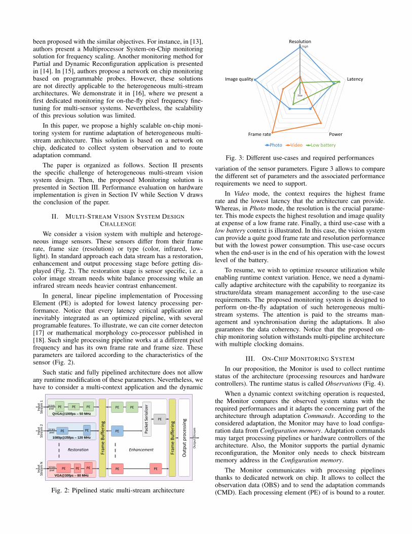
variation of the sensor parameters. Figure 3 allows to comparethe different set of parameters and the associated performancerequirements we need to support.
In Video mode, the context requires the highest framerate and the lowest latency that the architecture can provide.Whereas, in Photo mode, the resolution is the crucial parame-ter. This mode expects the highest resolution and image qualityat expense of a low frame rate. Finally, a third use-case with alow battery context is illustrated. In this case, the vision systemcan provide a quite good frame rate and resolution performancebut with the lowest power consumption. This use-case occurswhen the end-user is in the end of his operation with the lowestlevel of the battery.
To resume, we wish to optimize resource utilization whileenabling runtime context variation. Hence, we need a dynami-cally adaptive architecture with the capability to reorganize itsstructure/data stream management according to the use-caserequirements. The proposed monitoring system is designed toperform on-the-fly adaptation of such heterogeneous multi-stream systems. The attention is paid to the streams man-agement and synchronisation during the adaptations. It alsoguarantees the data coherency. Notice that the proposed on-chip monitoring solution withstands multi-pipeline architecturewith multiple clocking domains.
III. ON-CHIP MONITORING SYSTEM
In our proposition, the Monitor is used to collect runtimestatus of the architecture (processing resources and hardwarecontrollers). The runtime status is called Observations (Fig. 4).
When a dynamic context switching operation is requested,the Monitor compares the observed system status with therequired performances and it adapts the concerning part of thearchitecture through adaptation Commands. According to theconsidered adaptation, the Monitor may have to load configu-ration data from Configuration memory. Adaptation commandsmay target processing pipelines or hardware controllers of thearchitecture. Also, the Monitor supports the partial dynamicreconfiguration, the Monitor only needs to check bitstreammemory address in the Configuration memory.
The Monitor communicates with processing pipelinesthanks to dedicated network on chip. It allows to collect theobservation data (OBS) and to send the adaptation commands(CMD). Each processing element (PE) of is bound to a router.

Monitor and Adaptation Controllers
Monitor
Set of controllers
CommandsObservations
Commands Acknowledgments
Configuration
memory
Heterogeneous multi-stream
processing architecture
Fig. 4: On-Chip monitoring principle
The PEs on the extremities of a pipeline (the first and last)are bound to a specific RM router (Monitoring router) whileinternal PEs are bound to a RS router (Simple router).
RM is the interface router between processing pipelinesand the Monitor. Each RM router is connected to the Monitorthrough a CMD channel and an OBS channel (Fig. 5). Ob-servation data reach the Monitor through OBS channel whilethe Monitor sends commands to the pipelines through CMDchannel. OBS and CMD channels of RM routers are enoughto reach all the PEs of a pipeline. A RS router of a PEconveys its observation data to its right side neighbour routeruntil reaching the ending RM router. This later conveys theobservation data to the Monitor. In the same way, an adaptationcommand toward an internal PE is sent to the beginning RM
router of the concerning pipeline. This RM router forwardsthe command to its right side neighbour router until reachingthe target PE.
Number of PEs and pipelines in figure 5 are given onlyas an example to put ideas down. For reasons of clarity, onlyRestoration and Enhancement processing stages are presentedin this figure. But, the concept remains valid for Output pro-cessing stage too. In figure 5, we can see that the ending RM
routers have not their CMD channel. Actually, as mentionedbefore, the beginning RM router is enough to convey CMDdata to all the PEs of the pipeline. However, the CMD channel
Set of Hardware Controllers
Fra
me
Bu
ffe
r
Monitor
Partial
Reconfig. Host
Clock
Manager
Memory
Controller
Frame Synchro
Manager
1,6
Multi-
stream
PE
Pa
cke
tS
eri
ali
zer
1,1
PECMD
OBS
2,1
PE
N,1
PE
1,4
PECMD
OBS
1,3
PE OBS
2,3
PE
N,3
PE
1,2
PE
N,2
PE
1,5
PE
N,4
PE
N,6
PE
OBS
2,1
PE
Line
1
Line
2
Line
NRow 1 Row 2 Row 3 Row 4 Row 5 Row 6
Restoration Enhancement
i,j i,jRM router RS router
Configuration
memory
Fig. 5: Network on chip for monitoring of multi-sensor visionsystem
of the ending RM routers can be activated in case of a highlatency-critical application. Some pipelines may have less PEsthan others (ie : pipeline in line number 2). In this case, theywill have less RS routers but still two boundary RM routers.
To reduce the implementation cost, we adopt the princi-ple proposed in [11] where the adaptation commands wereencapsulated into the data stream header. We complete it byadding also the Observations into the header packets (Fig. 6).We propose to use a common communication interface andprotocol between PEs, routers and the Monitor. This interfaceis quite similar to ALTERA Avalon Streaming Interface orXILINX AXI4-Stream interface. This communication protocolis depicted in figure 6.
Clk
Start
Stop
Valid
Data
Ready
D0 D1 D2 D3HDR
Packetproducer/transmitter
Packetconsumer/receiver
StartStop
ValidDataReady
Fig. 6: Communication interface and protocol
A Start and Stop signals indicate respectively the beginningand the ending of a data packet. Between Start and Stopsignals, there are a given number of data phits (payload). AValid signal indicates the validity of the value presented inData. The value of Data while Start is high represents thepacket header. The header has a size of one phit. Ready signalis used as back pressure signal to prevent data loss. By the way,using a back pressure signal reduces buffer memory footprint.
TYPE SOURCE ID TARGET ID DATA ID DATA SIZE
St Ssi Sti Sdi Sds
Header PayloadPacket
PIPE PE PIPE PE
HDR D0 D2D1 D3 Dk
Fig. 7: Packet header description
Packet header details are given in figure 7. The packetheader has five fields : Type, Source ID, Target ID, Data ID andData size. Type indicates whether the packet is a pixel (PIX),an observation (OBS) or command (CMD) packet. Source andTarget IDs give information respectively about the producingand the targeting component of the packet. An OBS packethas necessarily the Monitor’s ID as Target ID. Meanwhile, asa CMD packet comes necessarily from the Monitor, its SourceID is the Monitor’s one. Data ID is used to distinguish severalOBS or CMD data respectively from or toward a same PE.Finally, Data size gives the number of data phits.
We added a fourth type of packet : frame synchronizationpacket (SYN). In traditional architecture, frame synchroniza-tion signal are distributed by a single wire. Here, we ratheruse a SYN packet from the Frame Synchronization Controllerto synchronize PEs of a pipeline.
Monitor clocking domain
Video clocking domain
SWITCHING MULTIPLEXERS
header decoder
header decoder
header decoder
CONTROLLER
CMD input
channel
CMD output channel
OBS input
channel
OBS output channel
Stream input channel
Stream output channel
PE input
PE output Frame
Synchronization
PE
Fig. 8: RM router internal structure
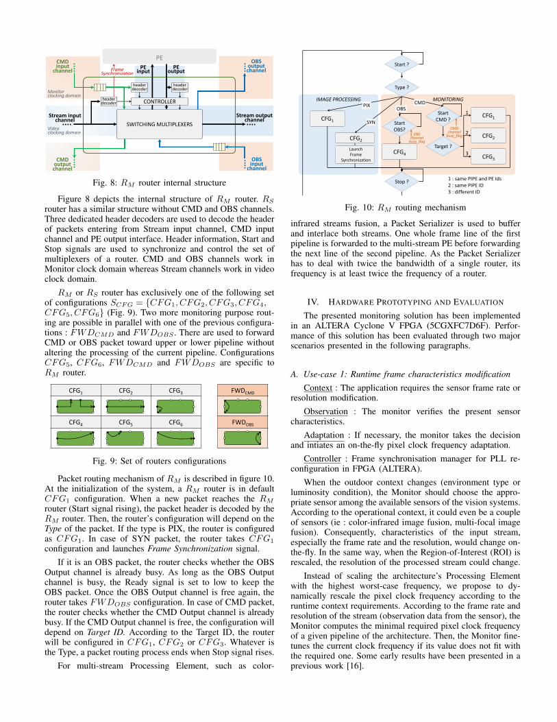
Figure 8 depicts the internal structure of RM router. RS
router has a similar structure without CMD and OBS channels.Three dedicated header decoders are used to decode the headerof packets entering from Stream input channel, CMD inputchannel and PE output interface. Header information, Start andStop signals are used to synchronize and control the set ofmultiplexers of a router. CMD and OBS channels work inMonitor clock domain whereas Stream channels work in videoclock domain.
RM or RS router has exclusively one of the following setof configurations SCFG = {CFG1, CFG2, CFG3, CFG4,CFG5, CFG6} (Fig. 9). Two more monitoring purpose rout-ing are possible in parallel with one of the previous configura-tions : FWDCMD and FWDOBS . There are used to forwardCMD or OBS packet toward upper or lower pipeline withoutaltering the processing of the current pipeline. ConfigurationsCFG5, CFG6, FWDCMD and FWDOBS are specific toRM router.
CFG1 CFG2 CFG3
CFG4 CFG5 CFG6
FWDCMD
FWDOBS
Exclusive set of configurations
Monitoring configurations
Fig. 9: Set of routers configurations
Packet routing mechanism of RM is described in figure 10.At the initialization of the system, a RM router is in defaultCFG1 configuration. When a new packet reaches the RM
router (Start signal rising), the packet header is decoded by theRM router. Then, the router’s configuration will depend on theType of the packet. If the type is PIX, the router is configuredas CFG1. In case of SYN packet, the router takes CFG1
configuration and launches Frame Synchronization signal.If it is an OBS packet, the router checks whether the OBS
Output channel is already busy. As long as the OBS Outputchannel is busy, the Ready signal is set to low to keep theOBS packet. Once the OBS Output channel is free again, therouter takes FWDOBS configuration. In case of CMD packet,the router checks whether the CMD Output channel is alreadybusy. If the CMD Output channel is free, the configuration willdepend on Target ID. According to the Target ID, the routerwill be configured in CFG1, CFG2 or CFG3. Whatever isthe Type, a packet routing process ends when Stop signal rises.
For multi-stream Processing Element, such as color-
MONITORING IMAGE PROCESSING
Start ?
Stop ?
Start CMD ?
Start OBS?
CFG2
CFG1
CFG4
CFG2
CFG3
CFG1
Type ?
Target ?
OBS channel
busy_flag
1
2
3
1 : same PIPE and PE Ids 2 : same PIPE ID 3 : different ID
OBS CMD PIX
SYN CMD
channel busy_flag
Launch Frame
Synchronization
Fig. 10: RM routing mechanism
infrared streams fusion, a Packet Serializer is used to bufferand interlace both streams. One whole frame line of the firstpipeline is forwarded to the multi-stream PE before forwardingthe next line of the second pipeline. As the Packet Serializerhas to deal with twice the bandwidth of a single router, itsfrequency is at least twice the frequency of a router.
IV. HARDWARE PROTOTYPING AND EVALUATION
The presented monitoring solution has been implementedin an ALTERA Cyclone V FPGA (5CGXFC7D6F). Perfor-mance of this solution has been evaluated through two majorscenarios presented in the following paragraphs.
A. Use-case 1: Runtime frame characteristics modification
Context : The application requires the sensor frame rate orresolution modification.
Observation : The monitor verifies the present sensorcharacteristics.
Adaptation : If necessary, the monitor takes the decisionand intiates an on-the-fly pixel clock frequency adaptation.
Controller : Frame synchronisation manager for PLL re-configuration in FPGA (ALTERA).
When the outdoor context changes (environment type orluminosity condition), the Monitor should choose the appro-priate sensor among the available sensors of the vision systems.According to the operational context, it could even be a coupleof sensors (ie : color-infrared image fusion, multi-focal imagefusion). Consequently, characteristics of the input stream,especially the frame rate and the resolution, would change on-the-fly. In the same way, when the Region-of-Interest (ROI) isrescaled, the resolution of the processed stream could change.
Instead of scaling the architecture’s Processing Elementwith the highest worst-case frequency, we propose to dy-namically rescale the pixel clock frequency according to theruntime context requirements. According to the frame rate andresolution of the stream (observation data from the sensor), theMonitor computes the minimal required pixel clock frequencyof a given pipeline of the architecture. Then, the Monitor fine-tunes the current clock frequency if its value does not fit withthe required one. Some early results have been presented in aprevious work [16].

Set of Hardware Controllers
Monitor
ClockManager
1,1
PE
2,1
PE
Frequency F1Resolution R1 @Frame Rate FR1
N,1
PE
1,3
PE
2,3
N,3
PE
1,2
PE
N,2
PE
Restoration
Configurationmemory
PE
Frequency F1Resolution R1 @Frame Rate FR1
Memory Controller
Frame Synchro Manager
StreamR1@FR1
Context switch
Stream resolution and frame rate modification
Stream and characteristics
from sensor
Set of Hardware Controllers
Monitor
ClockManager
1,1
PE
CMD
OBS
2,1
PE
Frequency F2Resolution R2 @Frame Rate FR2
N,1
PE
1,3
PE
2,3
N,3
PE
1,2
PE
N,2
PE
Restoration
Configurationmemory
PE
Frequency F2Resolution R2 @Frame Rate FR2
Memory Controller
Frame Synchro Manager
StreamR2@FR2
OBS
CMD
OBS
OBS
1
27
4 5 6
38
Fig. 11: Use-case 1 : stream frame rate and resolution adapta-tion
The adaptation of the clock frequency consists in re-configuring the PLL corresponding to the concerned clock(ALTERA reconfigurable PLL). The Monitor also adapts theFrame Synchronization signal’s period. Before any frequencyvalue adaptation, the Monitor sends command to the concernedpipeline to freeze the interface of the PEs.
1 Observation of the characteristics of the sensor from thesensor board.
2 Freezing command toward PEs of the concerned pipelinein case of any characteristic modification.
3 Freezing operation success information from PEs.4 New required frequency computation and frequency adap-
tation command toward the Clock Manager (then PLLReconfiguration).
5 Frame resolution modification command toward theMemory Controller.
6 Frame period time modification command toward theFrame Synchronization Manager.
7 End of freezing command toward PEs of the concernedpipeline (once all adaptation are completed).
8 End of freezing operation success information from PEs.
Notice that this concept is suitable for recent adaptive framerate and resolution sensor technology.
B. Use-case 2: Runtime sensor type switching
Context : New sensor connected to the system, switchingbetween sensor types used in the application.
Observation : Processing pipeline characteristics, sensorspecific informations.
Adaptation : The monitor initiates coarse-grain dynamicre-allocation of computation resources.
Controller : Partial and Dynamic Reconfiguration host ofFPGA (ALTERA).
This use-case illustrates the context of sensor type switch-ing while the frame rate and resolution values remain un-changed. When the outdoor luminosity condition changes, thetype of the sensor ought to be adapted. For instance, the visionsystem shifts to the infrared sensor for night vision when it
Set of Hardware Controllers
Monitor
Partial Reconfig.
Host
1,1
PE
2,1
PE
Persona A
N,1
PE
1,3
PE
2,3
N,3
PE
1,2
PE
N,2
PE
Restoration
Configurationmemory
PE
Persona B
Memory Controller
Frame Synchro Manager
Context switch
Sensor type modification (with same resolution and frame rate)
Stream and characteristics
from sensor
Set of Hardware Controllers
Monitor
ClockManager
1,1
PE
CMD
OBS
2,1
PE
Persona C
N,1
PE
1,3
PE
2,3
N,3
PE
1,2
PE
N,2
PE
Restoration
Configurationmemory
PE
Persona D
Memory Controller
Frame Synchro Manager
OBS
CMD
OBS
OBS
1
25
4
36
Fig. 12: Use-case 2 : stream type modification
is getting night. Sensor-specific pre-processing depends on thetype of the sensor. In a static architecture, when one of thevision system’s sensor is not used, its pre-processing resourcesare not re-usable for another active sensor. In our dynamicallyadaptive architecture, we propose to deploy sensor-specific pre-processing in reconfigurable resources. In case of sensor typeswitching, these resources would be re-allocated for the newactive sensor.
1 Observation of the characteristics of the sensor from thesensor board.
2 Freezing command toward PEs of the concerned pipelinein case of any characteristic modification.
3 Freezing operation success information from PEs.4 Decision of the new required image pre-processing and
PE adaptation request to the Partial Reconfiguration Host.5 End of freezing command toward PEs of the concerned
pipeline (once reconfiguration is completed).6 End of freezing operation success information from PEs.
For evaluation purpose, we simulated luminosity conditionswitching scenarios (day, evening, night). When the luminositycondition changes, the Monitor check the current active sen-sors. If the required sensor is not active, it shifts the sensorand adapts the sensor-specific image pre-processing pipeline.The pipeline adaptation consists in Partial and Dynamic Re-configuration of FPGA.
As the prototype is implemented in Altera Cyclone VFPGA, the Monitor sends reconfiguration request to the AlteraPR Core (cyclonev prblock) through a PR Host. The PRCore returns back a PR success or failure feedback to theMonitor. Once again, before any partial reconfiguration, theMonitor sends command to the concerned pipeline to freezethe interface of the PEs.
V. LATENCY COST EVALUATION
The proposed solution have been described in HDL andevaluated with a HDL simulator (ModelSim). Sensor pixelstreams have been simulated thanks to image vector input files.Several values of frequency, frame rate and resolution havebeen tested.
Any packet crosses a RM or RS router with a minimal

0
5
10
15
20
25
30
1 2 3 4 5 6
Contention-free Contention
Latency (cycles)
Number of pipelines
26
18
8
Fig. 13: Monitoring packet routing latency
latency of 2 cycles. These minimal 2 cycles can increase up to8 cycles in case of contention in the router. In figure 13, latencyperformance of typical pipelines are presented. We evaluatedthe latencies in case of 1 to 6 pipelines. For each case, theworst-case routing path latency has been reported. The bluecurve presents contention-free scenario whereas the orange onepresents the highest contention scenario. In case of a singlepipeline, there is no contention. For 3 pipelines-based multi-stream architecture, we have a worst-case latency of 20 cycles.That is to say, a CMD packet from the Monitor takes at most20 cycles to reach the farthest PE. In the same way, an OBSpacket from the farthest PE takes at most 20 cycles to reachthe Monitor. Besides, in addition to the interlacing operationlatency, the Packet Serializer adds an extra two cycles latency.
A. Synthesis results
Our synthesis results are based on Altera Cyclone V FPGA(5CGXFC7D6F) implementation with a 32 bits data size. Theheader fields sizes of this implementation are given in table I.Area overhead of the presented monitoring solution is givenin table II.
Field St Ssi Sti Sdi Sds
Size (bits) 2 8 8 10 4
TABLE I: Header implementation in 32 bits data
The area utilization of the monitoring solution has beencompared to a typical multi-stream reference design. Thisreference design needs 13 RM , 4 RS and 1 Packet Serializer.Area overhead comparison is given between brackets. In thisreference design, the proposed monitoring solution has lessthan 7% of overall area overhead.
Component ALUT Register Memory (bit)
RS 6 144 0RM 248 408 512
Packet Serializer 39 42 40 960Monitor 151 164 0
In reference design (%) 3 438 (6.7%) 6 086 (2.9%) 41 584 (0.9%)
TABLE II: Monitoring solution area overhead
The memory footprint of the Packet Serializer can beimproved by reducing the interlacing granularity. Otherwise,as RM and RS routers have a relative low area overhead,the solution is easily scalable for architectures with more than4 pipelines. In case of 64 bits data, we got the followingsynthesis results. RM (ALUT:289, Regs:620, Mem:1024) andRS (ALUT:10, Regs:280, Mem:0).
Nb. of pipeline 1 2 3 4 6
Clk Monitor 218 196 177 157 123Clk Video 237 223 210 198 193
TABLE III: Frequency performance (MHz)
Frequency performance of the proposed solution is pre-sented in table III. Typical multi-stream architectures have 3or 4 pipelines. Results in table III show a maximum affordablefrequency of 157 MHz for monitoring clock (Clk Monitor)and 198 MHz for pipeline clock (Clk Video) in case of 4pipelines. Within this performance, we can deal with 1080presolution up to 60 frame per second.
VI. CONCLUSION
In this paper, we introduced an original on-chip monitoringsolution for dynamically adaptive multi-stream vision architec-ture. This solution is based on a dedicated network on chip formonitoring observation and adaptation. It supports architec-ture with numerous heterogeneous pixel streams and multipleclocking domains. Evaluations on FPGA implementation showfair latency performance with a relatively low area overhead.Future works will focus on the extension of the proposednetwork on chip for pixel stream datapath flexibility.
REFERENCES
[1] Y. Yuan, H. Xu, Z. Miao, F. Liu, J. Zhang, and B. Chang, “Real-timeinfrared and visible image fusion system and fusion image evaluation,”in Photonics and Optoelectronics (SOPO), Symposium on, 2012.
[2] S. Yang, W. Liu, C. Deng, and X. Zhang, “Color fusion method for low-light-level and infrared images in night vision,” in Image and SignalProcessing (CISP), International Congress on, 2012.
[3] K. Hisatomi, M. Kano, K. Ikeya, M. Katayama, T. Mishina, Y. Iwadate,and K. Aizawa, “Depth estimation using an infrared dot projector andan infrared color stereo camera,” IEEE Transactions on Circuits andSystems for Video Technology, vol. PP, no. 99, pp. 1–1, 2016.
[4] S. Yang, W. Liu, C. Deng, and X. Zhang, “Color fusion methodfor low-light-level and infrared images in night vision,” in 2012 5thInternational Congress on Image and Signal Processing, Oct 2012, pp.534–537.
[5] C. Bahlmann, M. Pellkofer, J. Giebel, and G. Baratoff, “Multi-modalspeed limit assistants: Combining camera and gps maps,” in 2008 IEEEIntelligent Vehicles Symposium, June 2008, pp. 132–137.
[6] K. R. Sapkota, S. Roelofsen, A. Rozantsev, V. Lepetit, D. Gillet, P. Fua,and A. Martinoli, “Vision-based unmanned aerial vehicle detection andtracking for sense and avoid systems,” in 2016 IEEE/RSJ InternationalConference on Intelligent Robots and Systems (IROS), Oct 2016, pp.1556–1561.
[7] J. Serrano-Cuerda, M. T. Lopez, and A. Fernandez-Caballero, “Robusthuman detection and tracking in intelligent environments by informationfusion of color and infrared video,” in Intelligent Environments (IE),2011 7th International Conference on, 2011, pp. 354–357.
[8] O. W. Ibraheem, A. Irwansyah, J. Hagemeyer, M. Porrmann, andU. Rueckert, “A resource-efficient multi-camera gige vision ip corefor embedded vision processing platforms,” in 2015 InternationalConference on ReConFigurable Computing and FPGAs (ReConFig),Dec 2015, pp. 1–6.
[9] M. Darms and H. Winner, “A modular system architecture for sensordata processing of adas applications,” in IEEE Proceedings. IntelligentVehicles Symposium, 2005., June 2005, pp. 729–734.
[10] E. Dokladalova, R. Schmit, S. Pajaniradja, and S. Amadori, “Carvision:SOC architecture for dynamic vision systems from image captureto high level image processing,” in MEDEA DAC, no. 1, France,2006, p. 10pp., electronic version (4 pp.). [Online]. Available:https://hal-upec-upem.archives-ouvertes.fr/hal-00622297
[11] N. Ngan, E. Dokladalova, and M. Akil, “Dynamically adaptable nocrouter architecture for multiple pixel streams applications,” in Circuitsand Systems (ISCAS), 2012 IEEE International Symposium on. IEEE,2012, pp. 1006–1009.
[12] H. Giese, T. Vogel, A. Diaconescu, S. Gtz, N. Bencomo, K. Geihs,S. Kounev, and K. Bellman, State of the Art in Architectures for Self-Aware Computing Systems. Springer, 2017, ch. 8, pp. 237–275.
[13] M. H. Diana Goehringer, Mounir Chemaou, “Invited paper: On-chipmonitoring for adaptive heterogeneous multicore systems,” Reconfig-urable and Communication-centric Systems-on-Chip (ReCoSoC), 2012.
[14] X.-W. Wang, W.-N. Chen, C.-L. Peng, and H.-J. You, “Hardware-software monitoring techniques for dynamic partial reconfigurableembedded systems,” ICESS, International Conference on EmbeddedSoftware and Systems Symposia, 2008.
[15] L. Fiorin, G. Palermo, and C. Silvano, “A monitoring system for nocs,”in Proceedings of the Third International Workshop on Network on ChipArchitectures, ser. NoCArc ’10. ACM, 2010, pp. 25–30.
[16] A. Isavudeen, N. Ngan, E. Dokladalova, and M. Akil, “Auto-adaptivemulti-sensor architecture,” in IEEE International Symposium on Circuitsand Systems, ISCAS, 2016, pp. 2198–2201.
[17] P. Possa, N. Harb, E. Dokladalova, and C. Valderrama, “P2IP: A novellow-latency Programmable Pipeline Image Processor,” Microprocessorsand Microsystems: Embedded Hardware Design (MICPRO), p. In press,Jun. 2015. [Online]. Available: https://hal.archives-ouvertes.fr/hal-01171651
[18] J. Bartovsky, P. Dokladal, M. Faessel, E. Dokladalova, andM. Bilodeau, “Morphological CoProcessing Unit for EmbeddedDevices,” Journal of Real-Time Image Processing, 2015. [Online].Available: https://hal.archives-ouvertes.fr/hal-01251331