Highly rigid internal toolholders with excellent chip ... · Keeping the Customer First TAC boring...
32
Keeping the Customer First TAC boring bars Highly rigid internal toolholders with excellent chip evacuation Tungaloy Report No. 357-US Extended version
Transcript of Highly rigid internal toolholders with excellent chip ... · Keeping the Customer First TAC boring...

Keeping the Customer First
TAC boring bars
Highly rigid internal toolholders with excellent chip evacuation
Tungaloy Report No. 357-US
Extended version

T U N G A LOY
2
T U NU N G AG A LOYT U N G A LOY
New
PowerUp
2
Extensive simulation analysis has enabled Tungaloy to develop a highly-rigid Stream Jet Bar with the ideal tool geometry for excellent chip evacuation.
Seal Cap (Optional)
Chip pocket
Internal coolant supply
Attention: Please use the installation tools (e.g. a plastic hammer etc.), if diffi cult to ensure proper alignment
Screw (M6)Screw (M6)
Features
Minimum bore diameter from ø.177" (ø4.5 mm) Steel and carbide shank available Straight shank type available Can be used with internal coolant supply Well designed chip pocket for excellent chip evacuation Easy to adjust overhang due to marked scale on shank Improved rigidity for minimizing bar defl ection and
chatter by FEM (Finite Element Method) Added Z cutting edge style for back boring
Applicable sleeve for a variety of small lathes Supplied with Seal cap (optional) Suitably designed sleeve for directed external
coolant fl ow (see picture below)
W08 type chipbreaker Superior cutting edge due to fi ne grain carbide grade Two grades of inserts: SH730 (for general purpose),
TH10 (for non-ferrous) Expansion of corner radius rε = .0039" (0.1 mm) spec
on “EPGT52” and “WBGT52” insert types
Excellent performance for small diameter machining operations
Stable tool life and excellent chip control
Applicable for a wide variety of machines

3
Finite Analysis of the load transition
Rigidity comparison with a conventional boring bar (Illustrations)
Cutting performance
Oil hole design
Most Rigid Region of the toolholder
Improved chip evacuation
Shape of Stream Jet Bar
LargeSmall
Shape of Conventional boring bar
Conventional boring bar
Direction of chip evacuation
Conventional boring bar
Chip packing is likely to occur.
Direction of chipevacuation
Combination of the well designed chip pocket and coolant fl ow helps chips to effectively evacuate.
Section Section
Defl ection Defl ection
The rigidity of the bar in the direction of the principal force is maximized because the thickest portion of the head is located as close as possible to the cutting edge.Note: Load 1000N (Vc = 490 sfm, ap = .059", f = .008 ipr are assumed) A10-STUPR2-D14
The excellent chip evacuation minimizes tool failure caused by re-cutting chips and poor chip control. Damage to the work surface from chips is also eliminated.
Distance between the cutting edge and the oil hole is minimized.(Distance is reduced by 50% compared to existing boring bars.)
Large head design provides both high rigidity and good chip evacuation.
Region of great infl u-ence on the rigidity
of the toolholder
Pursuing high rigidity
Screw for oil hole*In the case of not using the oil hole, a special screw can be inserted to prevent chip coiling (optional).* Negative type only
About 20% reduction in defl ection compared with conventional bar
Increased rigidity for minimizing bar defl ection and chatter
New pocket design for excellent chip evacuation
The oil hole is positioned as close as possible to the cutting edge to ensure fl uid is fed directly to the cutting point.

T U N G A LOY
4
L/D 3 L/D 5
.008
.006
.004
.002
0 5 10 15 20 25 30
Marking specifi cations
Guide to L/D
For precision boring
Combination of the highly rigid carbide shank and the head geometry can increase the tool rigidity and improve chip evacuation.
Tool holder Cat. No.The minimum bore diameter is indicated in the Cat. No. The three-digit number at the end of the text indicates the minimum bore diameter.Example: Metric: D140 14.0 mmInch : D14 .875"
Applicable clamping screwCat. No. (Positive type only)
If screw is missing this detail simplifi es locating a replacement with Cat. No.
Scale of overhang lengthUseful for easy setting of the toolholder.
Applicable insert Cat. No.Can identify the insert size and relief angle at a glance. Simplifi ed tool management.
Cutting time (min)
The increased rigidity suppresses chatter, producing excellent surface fi nishes.Excellent chip evacuation minimizes damage to the surface caused by chip re-cutting. This further improves surface fi nish.
(Note) L : Overhang length, D: Shank diameter
ToolholderInsertWork material
Cutting speedDepth of cutFeedCutting fl uid
: A16Q-STUPR1103-D180: TPMT221-PS GT730:1045 (220HB): Boring (ø30 ~ 50 mm): Vc = 320 sfm: ap = .020": f = .008 ipr: Water soluble type
Steel shank Carbide shank
≤ ≤
Easy to use
Carbide shank type
Competitor's boring barBy supplying the optimum level of cutting fl uid, fl ank wear and rake face wear are suppressed, considerably improving tool life.
Improved tool life
Cor
ner
fl ank
wea
r w
idth
VB
c (in
ch)

5
72 8 9
4 5 63
T U PSA - R 2 D141
12
A
B
C
D
E
F
S
V
U
X*
Y
Z
G
J
K
L
N
P*
Q*
90°
75°
90°
45°
60°
91°
91°
91°
93°
75°
95°
95°
63°
62.5°
45°
45°
72.5°
93°
100°
80°
93°
C
B
N
P
R
L
I.C.
S T C RI.C. I.C. I.C.
7°
5°
0°
11°
C
D
E
S
T
V
Y
W
A
E
7 8 91 2
S
5 643
P
-
Designation System for TAC Boring Toolholders
Rhombic
80°
Rhombic
55°
Rhombic
75°
Square
Triangular
Rhombic
35°
Trigon
Y-shapeRhombic
25°(Tungaloy’s symbol)
Lever-lock type
Screw-on type
Sym
bo
l
Style
wit
hout
wit
hout
wit
hout
wit
hout
wit
hout
wit
h
wit
hw
ith
wit
hw
ith
wit
hout
wit
hw
itho
ut
wit
hw
itho
utw
ith
wit
hw
ith
wit
hout
Note: *mark.-TungaloyStandardNo mark: ISO standard
Mimimum boring diameter in shown in 16th of an inch.Ex. D14: ø .875"
Steel shankwith oil hole
Carbide shankwith steel head
and oil hole
Shank dia in shown in 16th ofan inch. Ex. 12: ø .750"
Hand of tool Insert size (I.C.) Min. bore. diameterShank composition Shank diameter
Cutting edge style Relief angle of insertInsert shapeClamping mechanism
Off
set

T U N G A LOY
6
SCLCR/L
SEXPR/L
STFCR/L
SDUCR/L
SVZCR/L
SVZBR/L
SVJCR/L
SDZCR/L
SDQCR/L
SVQBR/L
SVUCR/L
SYQBR/L
SVUBR/L
SVJBR/L
SYUBR/L
0 .375 .750 1.125 1.500 2.000
SCLPR/L
STUPR/L
STFPR/L
30˚
15.5˚
30˚
50˚
25.5˚
50˚
50˚
50˚
30˚
60˚
ø.313
ø.313
ø.500 ~ ø1.250ø.500 ~ ø1.250ø.375 ~ ø1.000
ø.313 ~ ø1.000
ø.313 ~ ø.625
ø.375 ~ ø.700
ø.375 ~ ø.625
ø.375 ~ ø.625
ø.340 ~ ø.700
ø.375 ~ ø.750
ø.375 ~ ø.625
ø.375 ~ ø.750
ø.625 ~ ø.750
ø.750
ø.500 ~ ø.625
ø.625
ø.875
ø.500 ~ ø.750
ø1.000
ø.625
ø.625
ø.625
ø.625
ø.625
ø.500 ~ ø.625
ø.250ø.250
ø.500 ø1.25
New
New MINI
New MINI
New MINI
ø.500 ø1.25ø.500 ø1.28
ø.438 ø1.250
ø.438 ø.875
ø.500 ø1.000
ø.500 ø875
ø.500 ø.875
ø.500 ø1.000
ø.625 ø.875
ø.625 ø1.000
ø.875 ø1.000
ø1.000
ø.625 ø.875
ø1.000
ø.875
ø.750 ø1.000
ø1.000
ø1.000
ø1.000
ø.750 ø.875ø.750 ø.875
ø1.000
ø.875 ø1.000
List of Stream Jet Bars A wide range of styles and sizes available
Style Shank Shank Minimum bore diameter (inch) type diameter
Inch
P. 22Boring and facingInsert type: EP
P. 8Boring and facingInsert type: CC P. 16BoringInsert type: WB
P. 14BoringInsert type: TP P. 10BoringInsert type: TP
P. 14Through boringInsert type: CP
P. 12BoringInsert type: SP
P. 19Through boringInsert type: SP
P. 18Internal profi lingInsert type: DC
P. 11Internal profi lingInsert type: VC
P. 17Internal profi lingInsert type: VB
P. 13Internal profi lingInsert type: DC
P. 20Internal profi lingInsert type: VC
P. 19Internal profi lingInsert type: VB
P. 21Internal retractingInsert type: DC
P. 22Internal retractingInsert type: VC
P. 24Internal undercut&prifi lingInsert type: YW
P. 25Boring&internal profi lingInsert type: YW
Steel
Carbide
Steel CarbideS-type
Steel
Carbide
Carbide
Steel
Carbide
Carbide
Steel
Carbide
Steel
Steel
Steel
Steel
Steel
Steel
Steel
Steel
Steel
Steel
Carbide
Steel
Carbide

7
SCLCR/L
SEXPR/L
30˚
SSKPR/L
STFCR/L
SDUCR/L
SVZCR/L
SDZCR/L
15.5˚SDQCR/L
SVQCR/L25.5˚
30˚
50˚
SVQBR/L25.5˚
SVUCR/L50˚
SVUBR/L50˚
0 10 20 30 40 50
SWUBR/L
SCLPR/L
STUPR/L
STFPR/L
ø4.5 ø7
ø4.5 ø7
ø6 ø8
ø5 ø27
ø5 ø27
ø8 ø34
ø8 ø27
ø10 ø27
ø10 ø22
ø10 ø27
ø10 ø20
ø6 ø8
ø10 ø27
ø10 ø27
ø20 ø31
ø13 ø32
ø16
ø13 ø30
ø13 ø27
ø18 ø32
ø20 ø32
ø24.5 ø34
ø13.5
ø13.5 ø21.5
ø17 ø30.5
ø13 ø25
ø17 ø30.5
ø14 ø25
ø18 ø22
ø16
ø50
ø50
New
New
New MINI
New MINI
New MINI
New MINI
Steel
Carbide
Steel
Carbide
Steel
Carbide
Steel
Carbide
Steel
Carbide
Steel
Carbide
Steel
Carbide
Steel
Steel
Carbide
Steel
Carbide
Steel
Carbide
Steel
Carbide
Steel
Carbide
Steel
Carbide
Steel
Carbide
Steel
P. 22Boring and facingInsert type: EP
P. 8Boring and facingInsert type: CC
P. 20Boring Insert type: WB
P. 14Boring Insert type: TP
P. 15Boring Insert type: TP
P. 8Through boringInsert type: CP
P. 14BoringInsert type: SP
P. 13Through boringInsert type: SP
P. 12Internal profi lingInsert type: DC
P. 19Internal profi lingInsert type: VC
P. 18Internal profi lingInsert type: VB
P. 11Internal profi lingInsert type: DC
P. 18Internal profi lingInsert type: VC
P. 17Internal profi lingInsert type: VB
P. 13Internal retractingInsert type: DC
P. 20Internal retractingInsert type: VC
Style Shank Shank Minimum bore diameter (mm) type diameter
Metric
ø4 ~ ø8ø4 ~ ø8
ø4 ~ ø25ø4 ~ ø25
ø5 ~ ø8ø5 ~ ø8
ø7 ~ ø32ø7 ~ ø25
ø8 ~ ø25ø8 ~ ø20
ø8 ~ ø25ø8 ~ ø16
ø8 ~ ø25ø8 ~ ø25
ø16 ~ ø25
ø10 ~ ø25ø10 ~ ø20
ø12 ~ ø40ø12 ~ ø25
ø16 ~ ø25ø16 ~ ø25
ø10 ~ ø25ø10 ~ ø20
ø10 ~ ø40ø10 ~ ø16
ø12 ~ ø25ø12 ~ ø25
ø12 ~ ø25ø12 ~ ø16
ø12

T U N G A LOY
8
切刃形状記号 L
SCLCR/LØ m
α
95°
12
θ
Øs
øDm rε (ft-lb)R L øDs f L1 L2 h f2 θ α
A06-SCLCR/L2-D08 .500 .375 .281 5.000 .750 .350 - 0˚ -9˚.016
CC21.5 CSTB-2.5S T-8F .89A08-SCLCR/L2-D11 .687 .500 .406 5.000 1.000 .475 - 0˚ -6˚A10-SCLCR/L3-D14 .875 .625 .531 7.000 1.250 .600 - 0˚ -7˚
CC32.5 CSTB-4S T-15F 2.21A12-SCLCR/L3-D16 1.000 .750 .594 7.000 1.438 .725 - 0˚ -5˚.031
A16-SCLCR/L3-D20 1.250 1.000 .687 7.000 1.750 .975 - 0˚ -4˚
SVJCR/L
SVJBR/L
SYQBR/L
SYUBR/L
30˚
60˚
0 10 20 30 40 50
SEZPR/L
SVZBR/L50˚
ø16 ~ ø32
ø4 ~ ø5
ø4 ~ ø5
ø12 ~ ø16
ø20 ~ ø25
ø12 ~ ø16
ø12 ~ ø16
ø16
ø12 ~ ø16
ø20 ø40
ø5.5 ø6.5
ø5.5 ø6.5
ø16 ø20
ø25 ø30
ø17 ø21.5
ø17 ø21.5
ø20
ø20 ø24.5
New MINI
øDm rε (N·m)R L øDs f L1 L2 h f2 θ α
A04F-SCLCR/L03-D050 5 4 2.5 80 8 3.8 - 0˚ -15˚0.2 CC03X1 CSTA-1.6 T-6F 0.6
A05F-SCLCR/L03-D060 6 5 3 80 9 4.8 - 0˚ -13˚A06G-SCLCR/L04-D070 7 6 3.5 90 11 5.75 - 0˚ -13˚
0.2 CC04T1 CSTB-2 T-6F 0.6A07G-SCLCR/L04-D080 8 7 4 90 12 6.75 - 0˚ -11˚A08H-SCLCR/L06-D100 10 8 5.5 100 16 7.5 - 0˚ -13˚ 0.4
CC0602 CSTB-2.5S T-8F 1.2A10F-SCLCR/L06-D120 12 10 6 80 20 9 - 0˚ -10˚ 0.4A10K-SCLCR/L06-D120 12 10 6 125 20 9 - 0˚ -10˚ 0.4A12H-SCLCR/L06-D140 14 12 7 100 24 11 - 0˚ -8˚ 0.4A12M-SCLCR/L06-D140 14 12 7 150 24 11 - 0˚ -8˚ 0.4
New MINI
New MINI
New MINI
New MINI
� : Stocked items
Boring & internal facing S-type (Positive, screw-on)
Right hand (R) shown
Cutting edge style L■ Steel shank
Internal toolholders
Parts Clamping Wrench screw
Stock Min Dimensions (in) Toolholder Cat. No. bore.dia. TorqueApplicable
inserts
Std.cornerradius
Inch
Style Shank Shank Minimum bore diameter (mm) type diameter
P. 19Internal retractingInsert type: VB
P. 21Internal retractingInsert type: EP
P. 22Internal sphere cuttingInsert type: VC
P. 21Internal sphere cuttingInsert type: VB P. 24Internal undercut and profi lingInsert type: YW
P. 25Internal profi lingInsert type: YW
Steel
Steel
Carbide
Steel
Steel
Steel
Carbide
Steel
Carbide
Parts Clamping Wrench screw
Stock Min Dimensions (mm) Toolholder Cat. No. bore.dia. TorqueApplicable
inserts
Std.cornerradius
Metric
Metric

9
øDm rε (N·m)R L øDs f L1 L2 h f2 θ α
A12H-SCLCR/L06-D160 16 12 9 100 24 11 - 0˚ -7˚ 0.4CC0602 CSTB-2.5S T-8F 1.2
A12M-SCLCR/L06-D160 16 12 9 150 24 11 - 0˚ -7˚ 0.4A16K-SCLCR/L09-D180 18 16 9 125 32 15 - 0˚ -9˚ 0.8
CC09T3 CSTB-4S T-15F 3.0
A16Q-SCLCR/L09-D180 18 16 9 180 32 15 - 0˚ -10˚ 0.8A16K-SCLCR/L09-D200 20 16 11 125 32 15 - 0˚ -9˚ 0.8A16Q-SCLCR/L09-D200 20 16 11 180 32 15 - 0˚ -9˚ 0.8A20R-SCLCR/L09-D220 22 20 11 200 32 18 - 0˚ -8˚ 0.8A25S-SCLCR/L09-D270 27 25 13.5 250 45 23 - 0˚ -6˚ 0.8
New MINI
New MINI
New MINI
New MINI
øDm rε (ft-lb)R L øDs f L1 L2 h f2 θ α
E06-SCLCR/L2-D08 .500 .375 .281 5.000 .750 .350 - 0˚ -9˚.016
CC21.5 CSTB-2.5S T-8F .89E08-SCLCR/L2-D11 .688 .500 .406 5.000 1.000 .475 - 0˚ -6˚E10-SCLCR/L2-D14 .875 .625 .531 7.000 1.250 .600 - 0˚ -7˚
CC32.5 CSTB-4S T-15F 2.21E12-SCLCR/L3-D16 1.000 .750 .594 7.000 1.438 .725 - 0˚ -5˚.031
E16-SCLCR/L3-D20 1.250 1.000 .687 10.000 1.750 .975 - 0˚ -4˚
øDm rε (N·m)R L øDs f L1 L2 h f2 θ α
E08G-SCLCR/L06-D100 10 8 5.5 90 22 7.5 - 0˚ -13˚ 0.4
CC0602 CSTB-2.5S T-8F 1.2E08K-SCLCR/L06-D100 10 8 5.5 125 22 7.5 - 0˚ -13˚ 0.4E10F-SCLCR/L06-D120 12 10 6 80 25 9 - 0˚ -10˚ 0.4E10H-SCLCR/L06-D120 12 10 6 100 25 9 - 0˚ -10˚ 0.4E10M-SCLCR/L06-D120 12 10 6 150 25 9 - 0˚ -10˚ 0.4E12G-SCLCR/L06-D140 14 12 7 90 27 11 - 0˚ -8˚ 0.4
CC0602 CSTB-2.5S T-8F 1.2
E12J-SCLCR/L06-D140 14 12 7 110 27 11 - 0˚ -8˚ 0.4E12Q-SCLCR/L06-D140 14 12 7 180 27 11 - 0˚ -8˚ 0.4E12G-SCLCR/L06-D160 16 12 9 90 27 11 - 0˚ -7˚ 0.4E12J-SCLCR/L06-D160 16 12 9 110 27 11 - 0˚ -7˚ 0.4E12Q-SCLCR/L06-D160 16 12 9 180 27 11 - 0˚ -7˚ 0.4E16H-SCLCR/L09-D180 18 16 9 100 32 15 - 0˚ -10˚ 0.8
CC09T3CSTB-4L060
T-15F 3.0
E16L-SCLCR/L09-D180 18 16 9 130 32 15 - 0˚ -10˚ 0.8E16R-SCLCR/L09-D180 18 16 9 200 32 15 - 0˚ -10˚ 0.8E16H-SCLCR/L09-D200 20 16 11 100 32 15 - 0˚ -9˚ 0.8E16L-SCLCR/L09-D200 20 16 11 130 32 15 - 0˚ -9˚ 0.8E16R-SCLCR/L09-D200 20 16 11 200 32 15 - 0˚ -9˚ 0.8E20S-SCLCR/L09-D220 22 20 11 250 36 18 - 0˚ -8˚ 0.8
CSTB-4SE25T-SCLCR/L09-D270 27 25 13.5 300 45 23 - 0˚ -6˚ 0.8
øDmR L øDs f L1 h α
S06-SCLCR/L2 .500 .375 .250 5.000 .335 12˚CC21.5 CSTB-2.5 T-8F
S08-SCLCR/L2 .625 .500 .313 6.000 .461 10˚S10-SCLCR/L3 .813 .625 .406 7.000 .547 10˚
CC32.5 CSTB-4B T-15FS12-SCLCR/L3 1.000 .750 .500 8.000 .670 8˚C06-SCLCR/L2 .470 .375 .245 5.000 .350 15˚
CC21.5 CSTB-2.5 T-8FC08-SCLCR/L2 .592 .500 .308 5.000 .475 15˚C10-SCLCR/L2 .760 .625 .401 7.000 .600 12˚C10-SCLCR/L3 .760 .625 .401 7.000 .600 12˚
CC32.5 CSTB-4S T-15FC12-SCLCR/L3 .920 .750 .495 7.000 .725 8˚C16-SCLCR/L3 1.280 1.000 .640 7.000 - -E06-SCLCR/L2 .470 .375 .245 5.000 .350 15˚
CC21.5 CSTB-2.5 T-8FE08-SCLCR/L2 .592 .500 .308 5.000 .475 15˚E10-SCLCR/L2 .760 .625 .401 7.000 .600 12˚E10-SCLCR/L3 .760 .625 .401 7.000 .600 12˚
CC32.5 CSTB-4S T-15FE12-SCLCR/L3 .920 .750 .495 7.000 .725 8˚E16-SCLCR/L3 1.250 1.000 .687 7.000 .975 4˚
■ Carbide shank
Parts Clamping Wrench screw
Stock Min Dimensions (mm) Toolholder Cat. No. bore.dia. TorqueApplicable
inserts
Std.cornerradius
Metric
Parts Clamping Wrench screw
Stock Min Dimensions (in) Toolholder Cat. No. bore.dia. TorqueApplicable
inserts
Std.cornerradius
Inch
Torque Parts Clamping Wrench screw
Stock Min Dimensions (mm) Toolholder Cat. No. bore.dia. Applicable
inserts
Std.cornerradius
Metric
When using a right or left hand insert, the right hand insert (R) is used for the left hand toolholders(SCLCL type), and the left hand insert (L) is used for the right hand toolholders (SCLCR type). � : Stocked items
Parts Clamping Wrench screw
Stock Min Dimensions (in) Toolholder Cat. No. bore.dia. Applicable
inserts
■ S-type
Ste
elC
arb
ide
Car
bid
e w
/Hol
e

T U N G A LOY
10
SCLPR/L
θ
Ø m
α
95°
12
Øs
øDm rε (ft-lb)R L øDs f L1 L2 h f2 θ αA06-SCLPR/L2-D08 .500 .375 .281 5.000 .750 .350 - +5˚ -5°
.016CP21.5
CSTB-2.5L042T-8F .89A08-SCLPR/L2-D11 .687 .500 .406 5.0001.000 .475 - +5˚ -2° CSTB-2.5S
A10-SCLPR/L3-D14 .875 .625 .531 7.0001.250 .600 - +5˚ -2˚ CP32.5 CSTB-4L070 T-15F 2.21
øDm rε (ft-lb)R L øDs f L1 L2 h f2 θ αE06-SCLPR/L2-D08 .500 .375 .281 5.000 .750 .350 - 0˚ -9°
.016 CP21.5 CP21.5 T-8F .89E08-SCLPR/L2-D11 .688 .500 .406 5.0001.000 .475 - 0˚ -6°E10-SCLPR/L3-D14 .875 .625 .531 7.0001.250 .600 - 0˚ -7˚ .031 CP32.5 CP32.5 T-15F 2.21
øDm rε (N·m)R L øDs f L1 L2 h f2 θ αA08H-SCLPR/L06-D100 10 8 5.5 100 16 7.5 - +5˚ -8° 0.4 CP0602 CSTB-2.5S T-8F 1.2A10K-SCLPR/L06-D120 12 10 6 125 20 9 - +5˚ -5° 0.4 CP0602 CSTB-2.5S T-8F 1.2A10K-SCLPR/L08-D120 12 10 6 125 20 9 - +5˚ -5˚ 0.4 CP0802 CSTB-3L042 T-9F 1.4A12M-SCLPR/L06-D140 14 12 7 150 24 11 - +5˚ -4˚ 0.4 CP0602 CSTB-2.5S T-8F 1.2A12M-SCLPR/L08-D140 14 12 7 150 24 11 - +5˚ -4˚ 0.4
CP0802 CSTB-3L050 T-9F 1.4A12M-SCLPR/L08-D160 16 12 9 150 24 11 - +5˚ -3° 0.4A16Q-SCLPR/L09-D180 18 16 9 180 32 15 - +5˚ -3.5˚ 0.8
CP0903 CSTB-4L060 T-15F 3.0A16Q-SCLPR/L09-D200 20 16 11 180 32 15 - +5˚ -3° 0.8A20R-SCLPR/L09-D220 22 20 11 200 36 18 - +5˚ -2˚ 0.8A25S-SCLPR/L09-D270 27 25 13.5 250 45 23 - +5˚ -1˚ 0.8
New
New
New
øDm rε (N·m)R L øDs f L1 L2 h f2 θ α
E08K-SCLPR/L06-D100 10 8 5.5 125 22 7.5 - +5˚ -8˚ 0.4 CP0602 CSTB-2.5S T-8F 1.2E10M-SCLPR/L06-D120 12 10 6 150 25 9 - +5˚ -5˚ 0.4 CP0602 CSTB-2.5S T-8F 1.2E10H-SCLPR/L08-D120 12 10 6 100 25 9 - +5˚ -5˚ 0.4
CP0802 CSTB-3L042 T-9F 1.4E10M-SCLPR/L08-D120 12 10 6 150 25 9 - +5˚ -5˚ 0.4E12Q-SCLPR/L06-D140 14 12 7 180 27 11 - +5˚ -4˚ 0.4 CP0602 CSTB-2.5S T-8F 1.2E12G-SCLPR/L08-D140 14 12 7 90 27 11 - +5˚ -4˚ 0.4
CP0802 CSTB-3L050 T-9F 1.4
E12J-SCLPR/L08-D140 14 12 7 110 27 11 - +5˚ -4˚ 0.4E12Q-SCLPR/L08-D140 14 12 7 180 27 11 - +5˚ -4˚ 0.4E12G-SCLPR/L08-D160 16 12 9 90 27 11 - +5˚ -3˚ 0.4E12J-SCLPR/L08-D160 16 12 9 110 27 11 - +5˚ -3˚ 0.4E12Q-SCLPR/L08-D160 16 12 9 180 27 11 - +5˚ -3˚ 0.4E16H-SCLPR/L09-D180 18 16 9 100 32 15 - +5˚ -3.5˚ 0.8
CP0903 CSTB-4L060 T-15F 3.0
E16L-SCLPR/L09-D180 18 16 9 130 32 15 - +5˚ -3.5˚ 0.8E16R-SCLPR/L09-D180 18 16 9 200 32 15 - +5˚ -3.5˚ 0.8E16H-SCLPR/L09-D200 20 16 11 100 32 15 - +5˚ -3˚ 0.8E16L-SCLPR/L09-D200 20 16 11 130 32 15 - +5˚ -3˚ 0.8E16R-SCLPR/L09-D200 20 16 11 200 32 15 - +5˚ -3˚ 0.8
New
New
New
Right hand (R) shown
Cutting edge style L
Boring & internal facing
■ Steel shank
Parts Clamping Wrench screw
Stock Min Dimensions (in) Toolholder Cat. No. bore.dia. Applicable
inserts
Std.cornerradius
S-type (Positive, screw-on)
Torque
Inch
� : Stocked items
■ Carbide shank
Parts Clamping Wrench screw
Stock Min Dimensions (in) Toolholder Cat. No. bore.dia. Applicable
inserts
Std.cornerradius
Torque
Inch
Parts Clamping Wrench screw
Stock Min Dimensions (mm) Toolholder Cat. No. bore.dia. Applicable
inserts
Std.cornerradius
Torque
Metric
When using a right or left hand insert, the right hand (R) insert is used for the left hand toolholders(SCLPL type), and the left hand insert (L) is used for the right hand toolholders (SCLPR type).
Parts Clamping Wrench screw
Stock Min Dimensions (mm) Toolholder Cat. No. bore.dia. Applicable
inserts
Std.cornerradius
Torque
Metric

11
SDQCR/L
Ø m
2
107.5°
α
2
θ
1
Øs15.5˚
øDm rε (ft-lb)R L øDs f L1 L2 h f2 θ αA06-SDQCR2-D10 .625 .375 .406 5.000 .750 .350 - 0˚ -7°
.016 CP21.5 CSTB-2.5B T-8F .89A08-SDQCR2-D11 .688 .500 .406 5.0001.000 .475 - 0˚ -6°A10-SDQCR2-D14 .875 .625 .531 7.0001.250 .600 - 0˚ -4˚
øDm rε (N·m)R L øDs f L1 L2 h f2 θ α
A10K-SDQCR/L07-D130 13 10 7.6 125 20 9 2.6 0˚ -8˚ 0.4DC0702 CSTB-2.5S T-8F 1.2A12M-SDQCR/L07-D160 16 12 8.6 150 24 11 2.6 0˚ -6˚ 0.4
A16Q-SDQCR/L07-D200 20 16 10.6 180 32 15 2.6 0˚ -5˚ 0.4A20R-SDQCR/L11-D250 25 20 13.7 200 36 18 3.7 0˚ -7˚ 0.8
DC11T3 CSTB-4S T-15F 3.0A25S-SDQCR/L11-D300 30 25 16.2 250 45 23 3.7 0˚ -4˚ 0.8
øDm rε (N·m)R L øDs f L1 L2 h f2 θ α
E10H-SDQCR/L07-D130 13 10 7.6 100 25 9 2.5 0˚ -8˚ 0.4
DC0702 CSTB-2.5S T-8F 1.2
E10M-SDQCR/L07-D130 13 10 7.6 150 25 9 2.6 0˚ -8˚ 0.4E12J-SDQCR/L07-D160 16 12 8.6 110 27 11 2.5 0˚ -6˚ 0.4E12Q-SDQCR/L07-D160 16 12 8.6 180 27 11 2.6 0˚ -6˚ 0.4E16L-SDQCR/L07-D200 20 16 10.6 130 32 15 2.5 0˚ -5˚ 0.4E16R-SDQCR/L07-D200 20 16 10.6 200 32 15 2.6 0˚ -5˚ 0.4E20S-SDQCR/L11-D250 25 20 13.7 250 36 18 3.7 0˚ -7˚ 0.8 DC11T3 CSTB-4S T-15F 3.0
� : Stocked items
Boring & internal profi ling S-type (Positive, screw-on)
Right hand (R) shown■ Steel shank
Cutting edge style Q
Parts Clamping Wrench screw
Stock Min Dimensions (in) Toolholder Cat. No. bore.dia. Applicable
inserts
Std.cornerradius
Torque
Inch
■ Carbide shank
When using a right or left hand insert, the right hand insert (R) is used for the left hand toolholders(SDQCL type), and the left hand insert (L) is used for the right hand toolholders (SDQCR type).
Parts Clamping Wrench screw
Stock Min Dimensions (mm) Toolholder Cat. No. bore.dia. Applicable
inserts
Std.cornerradius
Parts Clamping Wrench screw
Stock Min Dimensions (mm) Toolholder Cat. No. bore.dia. Applicable
inserts
Std.cornerradius
Torque
Torque
Metric

T U N G A LOY
12
SDUCR/L
f 2 L2 L1α
93°
f ØD
s
θ
hØDm
30˚
øDm rε (ft-lb)R L øDs f L1 L2 h f2 θ α
A06-SDUCR2-D10 .625 .375 .406 5.00 .750 .350 - 0˚ -8˚.016 DC21.5
CSTB-2.5
T-8F .89A08-SDUCR/L2-D11 .688 .500 .406 5.00 1.00 .475 .156 0˚ -6˚ CSTB-2.5B
A10-SDUCR2-D14 .875 .625 .531 7.00 1.25 .600 .219 0˚ -4˚ CSTB-2.5
øDm rε (N·m)R L øDs f L1 L2 h f2 θ α
A10K-SDUCR/L07-D130 13 10 7 125 20 9 2.0 0˚ -10˚ 0.4DC0702
CSTB-2.5ST-8F 1.2A12M-SDUCR/L07-D160 16 12 9.3 150 24 11 3.3 0˚ -6˚ 0.4
A16Q-SDUCR/L07-D200 20 16 11.3 180 32 15 3.3 0˚ -5˚ 0.4 CSTB-2.5A20R-SDUCR/L11-D270 27 20 16.1 200 36 18 6.1 0˚ -5˚ 0.8
DC11T3 CSTB-4S T-15F 3.0A25S-SDUCR/L11-D320 32 25 18.6 250 45 23 6.1 0˚ -4˚ 0.8
øDm rε (ft-lb)R L øDs f L1 L2 h f2 θ α
E06-SDUCR2-D10 .625 .375 .406 5.000 1.000 .375 -
0˚
-7˚.016 DC21.5
CSTB-2.5
T-8F .89E08-SDUCR2-D11 .688 .500 .406 5.000 1.062 .475 .156 -6˚ CSTB-2.5B
E10-SDUCR2-D14 .875 .625 .531 7.000 1.250 .600 .219 -4˚ CSTB-2.5
E12-SDUCR/L3-D16 1.000 .750 .594 7.000 1.438 .750 .219 -5˚ .031 DC31.5 CSTB-4S T-15F 2.21
øDm rε (N·m)R L øDs f L1 L2 h f2 θ α
E10H-SDUCR/L07-D130 13 10 7 100 25 9 1.9 5˚ -3.5˚ 0.4
DC0702CSTB-2.5S
T-8F 1.2
E10M-SDUCR/L07-D130 13 10 7 150 25 9 2.0 0˚ -10˚ 0.4E12J-SDUCR/L07-D160 16 12 9.3 110 27 11 3.2 0˚ -6˚ 0.4E12Q-SDUCR/L07-D160 16 12 9.3 180 27 11 3.3 0˚ -6˚ 0.4E16L-SDUCR/L07-D200 20 16 11.3 130 32 15 3.2 0˚ -5˚ 0.4E16R-SDUCR/L07-D200 20 16 11.3 200 32 15 3.3 0˚ -5˚ 0.4 CSTB-2.5E20S-SDUCR/L11-D270 27 20 16.1 250 36 18 6.1 0˚ -5˚ 0.8 DC11T3 CSTB-4S T-15F 3.0
Boring & internal profi ling
Cutting edge style U
S-type (Positive, screw-on)
Right hand (R) shown■ Steel shank
� : Stocked items
Parts Clamping Wrench screw
Stock Min Dimensions (inch) Toolholder Cat. No. bore.dia. TorqueApplicable
inserts
Std.cornerradius
Inch
Parts Clamping Wrench screw
Stock Min Dimensions (mm) Toolholder Cat. No. bore.dia. Applicable
inserts
Std.cornerradius
Torque
Metric
■ Carbide shank
Parts Clamping Wrench screw
Stock Min Dimensions (in) Toolholder Cat. No. bore.dia. TorqueApplicable
inserts
Std.cornerradius
Inch
When using a right or left hand insert, the right hand insert (R) is used for the left hand toolholders(SDUCL type), and the left hand insert (L) is used for the right hand toolholders (SDUCR type).
Parts Clamping Wrench screw
Stock Min Dimensions (mm) Toolholder Cat. No. bore.dia. Applicable
inserts
Std.cornerradius
Torque
Metric

13
SDZCR/L
L1L3
ØD
s
f
93°
f 2
30˚
øDm rε (ft-lb)R L øDs f L1 L2 L3 h f2 θ α
A10-SDZCR2-D14 .875 .625 .531 7.000 1.250 .500 .600 .219 0˚ -4˚ .016 DC21.5 CSTB-2.5 T-8F .89
øDm rε (N·m)R L øDs f L1 L2 L3 h f2 θ α
E12Q-SDZCR/L07-D180 18 12 10.5 180 - 12.5 11 4.5 0˚ -8˚ 0.4DC0702 CSTB-2.5 T-8F 1.2
E16R-SDZCR/L07-D220 22 16 12.5 200 - 12.5 15 4.5 0˚ -6˚ 0.4
SSKPR/L
θ
ØDm
α
75°
f
L2 L1Ø
Ds
h
øDm rε (N·m)R L øDs f L1 L2 h f2 θ α
A16Q-SSKPR/L09-D200 20 16 11 180 32 15 - +5˚ -6˚ 0.8SP0903 CSTB-4L060 T-15F 3.0
A20R-SSKPR/L09-D240 24 20 13 200 36 18 - +5˚ -2˚ 0.8A25S-SSKPR/L12-D310 31 25 17 250 45 23 - +5˚ -2˚ 0.8 SP1204 CSTB-5S T-20F 6.0
øDm rε (N·m)R L øDs f L1 L2 L3 h f2 θ α
A12M-SDZCR/L07-D140 14 12 10.5 150 30 12.5 11 4.5 0˚ -9˚ 0.4DC0702 CSTB-2.5 T-8F 1.2
A16Q-SDZCR/L07-D160 16 16 12.5 180 35 12.5 15 4.5 0˚ -8˚ 0.4A20R-SDZCR/L11-D200 20 20 15.5 200 40 15 18 5.5 0˚ -8˚ 0.8
DC11T3 CSTB-4S T-15F 3.0A25S-SDZCR/L11-D250 25 25 18 250 50 15 23 5.5 0˚ -6˚ 0.8
ØDm
L1L3
ØD
s
h
θ
α
f
93°
f 2
L2
Cutting edge style Z
Internal retracting S-type (Positive, screw-on)
Right hand (R) shown■ Steel shank
Parts Clamping Wrench screw
Stock Min Dimensions (in) Toolholder Cat. No. bore.dia. Applicable
inserts
Std.cornerradius
Carbide shankstyle
Torque
Inch
When using a right or left hand insert, the right hand insert (R) is used for the right hand toolholders(SDZCR type), and the left hand insert (L) is used for the left hand toolholders (SDZCL type).
■ Carbide shankTorque
� : Stocked items
Stock Min Dimensions (mm) Toolholder Cat. No. bore.dia.
Parts Clamping Wrench screw
Applicableinserts
Std.cornerradius
Cutting edge style K
S-type (Positive, screw-on)
Right hand (R) shown
When using a right or left hand insert, the right hand insert (R) is used for the left hand toolholders(SSKPL type), and the left hand insert (L) is used for the right hand toolholders (SSKPR type).
■ Parts Clamping Wrench screw
Stock Min Dimensions (mm) Toolholder Cat. No. bore.dia. Applicable
inserts
Std.cornerradius
■ Steel shank
Through boring
Torque
Metric Parts Clamping Wrench screw
Stock Min Dimensions (mm) Toolholder Cat. No. bore.dia. Applicable
inserts
Std.cornerradius
Torque

T U N G A LOY
14
øDm rε (N·m)R L øDs f L1 L2 h f2 θ α
A08H-STFCR/L09-D100 10 8 5.5 100 16 7.5 0.6 0˚ -12˚ 0.4TC0902 CSTB-2.2S T-7F 0.9
A10K-STFCR/L09-D120 12 10 6.5 125 20 9 0.6 0˚ -10˚ 0.4A10K-STFCR/L1102-D120 12 10 6.5 125 20 9 0.6 0˚ -10˚ 0.4 TC1102 CSTB-2.5 T-8F 1.2A10K-STFCR/L1103-D120 12 10 6.5 125 20 9 0.6 0˚ -13˚ 0.4 TC1103 CSTB-2.5 T-8F 1.2A12M-STFCR/L09-D140 14 12 7 150 24 11 0.5 0˚ -8˚ 0.4 TC0902 CSTB-2.2 T-7F 0.9A12M-STFCR/L1102-D140 14 12 7 150 24 11 0.5 0˚ -8˚ 0.4 TC1102 CSTB-2.5 T-8F 1.2A12M-STFCR/L1103-D140 14 12 7 150 24 11 0.5 0˚ -10˚ 0.4 TC1103 CSTB-2.5 T-8F 1.2A16Q-STFCR/L09-D180 18 16 9 180 32 15 0.6 0˚ -6˚ 0.4 TC0902 CSTB-2.2 T-7F 0.9A16Q-STFCR/L1102-D180 18 16 9 180 32 15 0.6 0˚ -6˚ 0.4 TC1102 CSTB-2.5 T-8F 1.2A16Q-STFCR/L1103-D180 18 16 9 180 32 15 0.5 0˚ -7˚ 0.4 TC1103 CSTB-2.5 T-8F 1.2A20R-STFCR/L1102-D220 22 20 11 200 36 18 0.5 0˚ -4˚ 0.4 TC1102 CSTB-2.5 T-8F 1.2A20R-STFCR/L16-D220 22 20 11 200 36 18 0.4 0˚ -7˚ 0.8
TC16T3 CSTB-4M T-15F 3.0A25S-STFCR/L16-D270 27 25 13.5 250 45 23 0.4 0˚ -5˚ 0.8
New
New
New
øDm rε (N·m)R L øDs f L1 L2 h f2 θ α
E08K-STFCR/L09-D100 10 8 5.5 125 22 7.5 0.6 0˚ -12˚ 0.4TC0902 CSTB-2.2S T-7F 0.9
E10M-STFCR/L09-D120 12 10 6.5 150 25 9 0.6 0˚ -10˚ 0.4E10M-STFCR/L1102-D120 12 10 6.5 150 25 9 0.6 0˚ -10˚ 0.4 TC1102 CSTB-2.5 T-8F 1.2E10M-STFCR/L1103-D120 12 10 6.5 150 25 9 0.7 0˚ -13˚ 0.4 TC1103 CSTB-2.5 T-8F 1.2E12Q-STFCR/L09-D140 14 12 7 180 27 11 0.6 0˚ -8˚ 0.4 TC0902 CSTB-2.2 T-7F 0.9E12Q-STFCR/L1102-D140 14 12 7 180 27 11 0.6 0˚ -8˚ 0.4 TC1102 CSTB-2.5 T-8F 1.2E12Q-STFCR/L1103-D140 14 12 7 180 27 11 0.5 0˚ -10° 0.4 TC1103 CSTB-2.5 T-8F 1.2E16R-STFCR/L09-D180 18 16 9 200 32 15 0.6 0˚ -6˚ 0.4 TC0902 CSTB-2.2 T-7F 0.9E16R-STFCR/L1102-D180 18 16 9 200 32 15 0.6 0˚ -6˚ 0.4 TC1102 CSTB-2.5 T-8F 1.2E16R-STFCR/L1103-D180 18 16 9 200 32 15 0.5 0˚ -7° 0.4 TC1103 CSTB-2.5 T-8F 1.2E20S-STFCR/L1102-D220 22 20 11 250 36 18 0.6 0˚ -4˚ 0.4 TC1102 CSTB-2.5 T-8F 1.2E20S-STFCR/L16-D220 22 20 11 250 36 18 0.6 0˚ -7˚ 0.8
TC16T3 CSTB-4M T-15F 3.0E25T-STFCR/L16-D270 27 25 13.5 300 45 23 0.5 0˚ -5˚ 0.8
New
New
New
øDm rε (ft-lb)R L øDs f L1 L2 h f2 θ α
E06-STFCR/L2-D08 .500 .375 .281 5.000 1.000 .350 .024 0˚ -9˚ .016TC21.5 CSTB-2.5 T-8F .89E08-STFCR2-D11 .688 .500 .406 5.000 1.062 .475 .024 0˚ -6˚ .016
E10-STFCR2-D14 .875 .625 .531 7.000 1.250 .600 .024 0˚ -5˚ .016E12-STFCR3-D16 1.000 .750 .594 7.000 1.438 .750 .039 0˚ -5˚ .031 TC32.5 CSTB-4S T15-F 2.21
STFCR/L
θ
α
Ø m
Øs
2
12
91°
øDm rεR L øDs f L1 L2 h θ α
A06M-STFCR/L-2 .480 .375 .256 6.000 .625 .340 0˚ 11˚ .016TC21.5 TS-25.45-6M2A08R-STFCR/L-2 .600 .500 .312 8.000 .748 .460 0˚ 9˚ .016
A10S-STFCR/L-2 .770 .625 .406 10.000 1.250 .575 0˚ 7˚ .016A12S-STFCR/L-3 .930 .750 .500 10.000 1.875 .700 0˚ 6˚ .031 TC32.5 TS-4.7-10M1
Parts Clamping Wrench screw
Stock Min Dimensions (mm) Toolholder Cat. No. bore.dia. Applicable
inserts
Std.cornerradius
Torque
When using a right or left hand insert, the right hand insert (R) is used for the left hand toolholders(STFCL type), and the left hand insert (L) is used for the right hand toolholders (STFCR type).
■ Carbide shank
Parts Clamping Wrench screw
Stock Min Dimensions (mm) Toolholder Cat. No. bore.dia. Applicable
inserts
Std.cornerradius
Torque
� : Stocked items
Parts Clamping Wrench screw
Stock Min Dimensions (in) Toolholder Cat. No. bore.dia. TorqueApplicable
inserts
Std.cornerradius
Inch
Metric
Metric
Boring S-type (Positive, screw-on)
Cutting edge style FRight hand (R) shown
■ Steel shankInch
Parts
Clamping screw
Stock Min Dimensions (in) Toolholder Cat. No. bore.dia. Applicable
inserts
Std.cornerradius

15
STFPR/L
θ
α
Ø m
Øs
2
12
91°
øDm rε (N·m)R L øDs f L1 L2 h f2 θ α
A08H-STFPR/L09-D100 10 8 5.5 100 16 7.5 0.7 +5˚ -8˚ 0.4 TP0902 CSTB-2.2S T-7F 0.9A10K-STFPR/L1102-D120 12 10 6.5 125 20 9 0.7 +5˚ -6˚ 0.4 TP1102 CSTB-2.5B T-8F 1.2A10K-STFPR/L1103-D120 12 10 6.5 125 20 9 0.7 +5˚ -7˚ 0.4 TP1103* CSTB-3L050 T-9F 1.4A12M-STFPR/L1102-D140 14 12 7 150 24 11 0.6 +5˚ -4˚ 0.4 TP1102 CSTB-2.5 T-8F 1.2A12M-STFPR/L1103-D140 14 12 7 150 24 11 0.6 +5˚ -4˚ 0.4
TP1103* CSTB-3S T-9F 1.4A16Q-STFPR/L1103-D180 18 16 9 180 32 15 0.7 +5˚ -2˚ 0.4A16Q-STFPR/L13-D180 18 16 9 180 32 15 0.7 +5˚ -2˚ 0.4
TP1303CSTB-3S
T-9F 1.4A20R-STFPR/L13-D220 22 20 11 200 36 18 0.8 +5˚ -2˚ 0.4 CSTB-3
A25S-STFPR/L16-D270 27 25 13.5 250 45 23 0.6 +5˚ -1˚ 0.4 TP16T3 CSTB-4M T-15F 3.0
øDm rε (N·m)R L øDs f L1 L2 h f2 θ α
E08K-STFPR/L09-D100 10 8 5.5 125 22 7.5 0.7 +5˚ -8˚ 0.4 TP0902 CSTB-2.2S T-7F 0.9E10M-STFPR/L1102-D120 12 10 6.5 150 25 9 0.7 +5˚ -6˚ 0.4 TP1102 CSTB-2.5B T-8F 1.2E10M-STFPR/L1103-D120 12 10 6.5 150 25 9 0.7 +5˚ -7˚ 0.4 TP1103* CSTB-3L050 T-9F 1.4E12Q-STFPR/L1102-D140 14 12 7 180 27 11 0.6 +5˚ -4˚ 0.4 TP1102 CSTB-2.5 T-8F 1.2E12Q-STFPR/L1103-D140 14 12 7 180 27 11 0.6 +5˚ -4˚ 0.4
TP1103* CSTB-3S T-9F 1.4E16R-STFPR/L1103-D180 18 16 9 200 32 15 0.7 +5˚ -2˚ 0.4E16R-STFPR/L13-D180 18 16 9 200 32 15 0.7 +5˚ -2˚ 0.4
TP1303CSTB-3S
T-9F 1.4E20S-STFPR/L13-D220 22 20 11 250 36 18 0.8 +5˚ -2˚ 0.4 CSTB-3
øDm rε (ft-lb)R L øDs f L1 L2 h f2 θ α
E06-STFPR2-D08 .500 .375 .281 5.000 1.000 .350 .024 0˚ -5˚.016 TP21.5
CSTB-2.5BT-8F .89E08-STFPR2-D11 .688 .500 .406 5.000 1.062 .475 .028 0˚ -3˚
CSTB-2.5E10-STFPR2-D14 .875 .625 .531 7.000 1.250 .605 .031 0˚ -2˚E12-STFPR/L3-D16 1.000 .750 .594 7.000 1.438 .725 .028 0˚ -2˚ .031 TP32.5 CSTB-4S T-15F 2.21
Cutting edge style FRight hand (R) shown
Blind hole boring S-type (Positive, screw-on)
When using a right or left hand insert, the right hand insert (R) is used for the left hand toolholders(STFPL type), and the left hand insert (L) is used for the right hand toolholders (STFPR type).* TPGH1103 is not applicable.
■ Carbide shank
Parts Clamping Wrench screw
Stock Min Dimensions (mm) Toolholder Cat. No. bore.dia. Applicable
inserts
Std.cornerradius
■ Steel shankTorque
� : Stocked items
Parts Clamping Wrench screw
Stock Min Dimensions (mm) Toolholder Cat. No. bore.dia. Applicable
inserts
Std.cornerradius
Torque
Parts Clamping Wrench screw
Stock Min Dimensions (in) Toolholder Cat. No. bore.dia. TorqueApplicable
inserts
Std.cornerradius
Metric
Inch

T U N G A LOY
16
STUPR/L
θ
ØDm
α
95°
f
L2f 2
L1
ØD
s
h
øDm rε (N·m)R L øDs f L1 L2 h f2 θ α
A07G-STUPR/L07-D080 8 7 4 90 12 6.75 0.4 +5˚ -10˚ 0.4 TP0701 CSTB-2.2L038 T-7F 0.9A08H-STUPR/L07-D080 8 8 4 100 19.5 7.5 0.5 +5˚ -10˚ 0.4 TP0701 CSTB-2.2L038 T-7F 0.9A08H-STUPR/L09-D100 10 8 5.5 100 16 7.5 0.6 +5˚ -8˚ 0.4 TP0902 CSTB-2.2L038 T-7F 0.9A10F-STUPR/L1102-D120 12 10 6.5 80 20 9 1.4 +5˚ -6˚ 0.4
TP1102 CSTB-2.5S T-8F 1.2A10K-STUPR/L1102-D120 12 10 6.5 125 20 9 0.7 +5˚ -6˚ 0.4A10K-STUPR/L1103-D120 12 10 6.5 125 20 9 0.6 +5˚ -10˚ 0.4 TP1103* CSTB-3L050 T-9F 1.4A12H-STUPR/L1102-D140 14 12 7 100 24 11 0.9 +5˚ -4˚ 0.4
TP1102 CSTB-2.5B T-8F 1.2A12M-STUPR/L1102-D140 14 12 7 150 24 11 0.7 +5˚ -4˚ 0.4A12M-STUPR/L1103-D140 14 12 7 150 24 11 0.6 +5˚ -6˚ 0.4 TP1103* CSTB-3L050 T-9F 1.4A12H-STUPR/L1102-D160 16 12 9 100 24 11 0.6 +5˚ -3˚ 0.4
TP1102 CSTB-2.5B T-8F 1.2A12M-STUPR/L1102-D160 16 12 9 150 24 11 0.6 +5˚ -3˚ 0.4A16K-STUPR/L13-D180 18 16 9 125 32 15 0.9 +5˚ -3˚ 0.4 TP1303 CSTB-3S T-9F 1.4A16Q-STUPR/L1103-D180 18 16 9 180 32 15 0.8 +5˚ -4˚ 0.4 TP1103* CSTB-3S T-9F 1.4A16Q-STUPR/L13-D180 18 16 9 180 32 15 0.6 +5˚ -3˚ 0.4 TP1303 CSTB-3S T-9F 1.4A16K-STUPR/L13-D200 20 16 11 125 32 15 0.6 +5˚ -3˚ 0.4
TP1303CSTB-3S T-9F 1.4A16Q-STUPR/L13-D200 20 16 11 180 32 15 0.6 +5˚ -3˚ 0.4
A20R-STUPR/L1103-D220 22 20 11 200 36 18 0.7 +5˚ -2˚ 0.4 TP1103*A20R-STUPR/L13-D220 22 20 11 200 36 18 0.7 +5˚ -2˚ 0.4 TP1303 CSTB-3 T-9F 1.4A25S-STUPR/L16-D270 27 25 13.5 250 45 23 0.5 +5˚ -1˚ 0.8
TP16T3 CSTB-4M T-15F 3.0A32T-STUPR/L16-D340 34 32 17 300 50 30 0.7 +5˚ 0˚ 0.8
øDm rε (N·m)R L øDs f L1 L2 h f2 θ αE07H-STUPR/L07-D080 8 7 4 100 14 6.75 0.3 +5˚ -10˚ 0.4 TP0701 CSTB-2.2L038 T-7F 0.9E08G-STUPR/L07-D080 8 8 4 90 44.5 7.5 0.5 +5˚ -10˚ 0.4
TP0701 CSTB-2.2L038 T-7F 0.9E08K-STUPR/L07-D080 8 8 4 125 44.5 7.5 0.5 +5˚ -10˚ 0.4E08G-STUPR/L09-D100 10 8 5.5 90 22 7 0.6 +5˚ -8˚ 0.4 TP0902 CSTB-2.2L038 T-7F 0.9E08K-STUPR/L09-D100 10 8 5.5 125 22 7 0.6 +5˚ -8˚ 0.4
New MINI
New MINI
øDm rε (ft-lb)R L øDs f L1 L2 h f2 θ αA05-STUPR/L7-D07 .438 .313 .250 5.000 .625 .288 - 5˚ -7˚
.016
TP73 CSTB-2.2S T-7F .66A06-STUPR/L2-D08 .500 .375 .281 5.000 .750 .350 - 5˚ -5˚
TP21.5CSTB-2.5S
T-8F .89A08-STUPR/L2-D11 .688 .500 .406 5.000 1.000 .475 - 5˚ -3˚ CSTB-2.5B
A10-STUPR/L2-D14 .875 .625 .531 7.000 1.250 .600 - 5˚ 0˚CSTB-2.5
A10-STUPR/L2.5-D14 .875 .625 .531 7.000 1.250 .600 - 5˚ -2˚ TP2.52A12-STUPR/L3-D16 1.000 .750 .594 7.000 1.437 .725 - 5˚ -2˚ .031 TP32.5 CSTB-4M T-15F 2.21A16-STUPR/L3-D20 1.250 1.000 .688 7.000 1.750 .975 - 5˚ 0˚
øDm rε (ft-lb)R L øDs f L1 L2 h f2 θ αE05-STUPR7-D07 .438 .313 .250 5.000 .875 .288 - 5˚ -7˚
.016
TP73 CSTB-2.2S T-7F .66E06-STUPR2-D08 .500 .375 .281 5.0001.000 .350 - 5˚ -5˚ TP21.5 CSTB-2.5S T-8F
.89E08-STUPR2-D11 .688 .500 .406 5.0001.062 .475 - 5˚ -3˚ TP21.5 CSTB-2.5B T-8F
E10-STUPR2.5-D14 .875 .625 .531 7.0001.250 .600 - 5˚ -2˚ TP2.52 CSTB-3 T-9F 1.03
■ Steel shank
Boring S-type (Positive, screw-on)
Right hand (R) shown
■ Carbide shank
Parts Clamping Wrench screw
Stock Min Dimensions (mm) Toolholder Cat. No. bore.dia. Applicable
inserts
Std.cornerradius
Parts Clamping Wrench screw
Stock Min Dimensions (mm) Toolholder Cat. No. bore.dia. Applicable
inserts
Std.cornerradius
Cutting edge style U
Torque
Torque
� : Stocked items
Parts Clamping Wrench screw
Stock Min Dimensions (in) Toolholder Cat. No. bore.dia. TorqueApplicable
inserts
Std.cornerradius
Metric
Inch
Parts Clamping Wrench screw
Stock Min Dimensions (in) Toolholder Cat. No. bore.dia. TorqueApplicable
inserts
Std.cornerradius
Inch
Metric

17
SVQBR/L
θ
ØDm
α
117.5°
f
f 2
L1L2
ØD
s
h
25.5˚
øDm rε (N·m)R L øDs f L1 L2 h f2 θ α
E12Q-SVQBR/L11-D170 17 12 10.5 180 27 11 4.5 -5˚ -10˚ 0.4VB1103 CSTB-2.5 T-8F 1.2E16R-SVQBR/L11-D215 21.5 16 13 200 32 15 5 -5˚ -8˚ 0.4
E20S-SVQBR/L11-D255 25.5 20 15 250 36 18 5 -5˚ -6˚ 0.4E25T-SVQBR/L16-D305 30.5 25 17.5 300 45 23 5 -5˚ -8˚ 0.8 VB1604 CSTB-3.5 T-15F 3.0
øDm rε (N·m)R L øDs f L1 L2 h f2 θ α
A12M-SVQBR/L11-D170 17 12 10.5 150 24 11 4.5 -5˚ -10˚ 0.4VB1103 CSTB-2.5 T-8F 1.2A16Q-SVQBR/L11-D215 21.5 16 13 180 30 15 5 -5˚ -8˚ 0.4
A20R-SVQBR/L11-D255 25.5 20 15 200 36 18 5 -5˚ -6˚ 0.4A25S-SVQBR/L16-D305 30.5 25 17.5 250 45 23 5 -5˚ -8˚ 0.8 VB1604 CSTB-3.5 T-15F 3.0
øDm rε (N·m)R L øDs f L1 L2 h f2 θ α
E10F-STUPR/L1102-D120 12 10 6.5 80 25 9 0.5 +5˚ -6° 0.4TP1102 CSTB-2.5S T-8F 1.2E10H-STUPR/L1102-D120 12 10 6.5 100 25 9 0.6 +5˚ -6˚ 0.4
E10M-STUPR/L1102-D120 12 10 6.5 150 25 9 0.6 +5˚ -6˚ 0.4E10M-STUPR/L1103-D120 12 10 6.5 150 25 9 0.7 +5˚ -10˚ 0.4 TP1103* CSTB-3L050 T-9F 1.4E12G-STUPR/L1102-D140 14 12 7 90 27 11 0.9 +5˚ -4˚ 0.4
TP1102CSTB-2.5S T-8F 1.2
E12J-STUPR/L1102-D140 14 12 7 110 27 11 0.6 +5˚ -4˚ 0.4CSTB-2.5B T-8F 1.2E12Q-STUPR/L1102-D140 14 12 7 180 27 11 0.6 +5˚ -4˚ 0.4
E12Q-STUPR/L1103-D140 14 12 7 180 27 11 0.7 +5˚ -6˚ 0.4 TP1103* CSTB-3L050 T-9F 1.4E12G-STUPR/L1102-D160 16 12 9 90 27 11 0.6 +5˚ -3˚ 0.4
TP1102 CSTB-2.5B T-8F 1.2E12J-STUPR/L1102-D160 16 12 9 110 27 11 0.6 +5˚ -3˚ 0.4E12Q-STUPR/L1102-D160 16 12 9 180 27 11 0.6 +5˚ -3˚ 0.4E16H-STUPR/L13-D180 18 16 9 100 32 15 0.9 +5˚ -3˚ 0.4 TP1303 CSTB-3S T-9F 1.4E16R-STUPR/L1103-D180 18 16 9 200 32 15 0.8 +5˚ -4˚ 0.4 TP1103* CSTB-3S T-9F 1.4E16L-STUPR/L13-D180 18 16 9 130 32 15 0.6 +5˚ -3˚ 0.4
TP1303 CSTB-3S T-9F 1.4E16R-STUPR/L13-D180 18 16 9 200 32 15 0.6 +5˚ -3˚ 0.4E16H-STUPR/L13-D200 20 16 11 100 32 15 0.6 +5˚ -3˚ 0.4E16L-STUPR/L13-D200 20 16 11 130 32 15 0.6 +5˚ -3˚ 0.4
TP1303 CSTB-3S T-9F 1.4E16R-STUPR/L13-D200 20 16 11 200 32 15 0.6 +5˚ -3˚ 0.4E20S-STUPR/L1103-D220 22 20 11 250 36 18 0.7 +5˚ -2˚ 0.4 TP1103* CSTB-3S T-9F 1.4E20S-STUPR/L13-D220 22 20 11 250 36 18 0.6 +5˚ -2˚ 0.4 TP1303 CSTB-3 T-9F 1.4E25T-STUPR/L16-D270 27 25 13.5 300 45 23 0.5 +5˚ -1˚ 0.8 TP16T3 CSTB-4M T-15F 3.0
øDm rε (ft-lb)R L øDs f L1 L2 h f2 θ α
A10-SVQBR2-D16 1.000 .625 .500 7.000 1.25 .600 .188 -5˚ -6˚ .016 VB1103 CSTB-2.5 T-8F .89
Cutting edge style QRight hand (R) shown
Boring & internal profi ling S-type (Positive, screw-on)
■ Steel shank
■ Carbide shank
When using a right or left hand insert, the right hand insert (R) is used for the left hand toolholders(SVQBL type), and the left hand insert (L) is used for the right hand toolholders (SVQBR type).
Parts Clamping Wrench screw
Stock Min Dimensions (mm) Toolholder Cat. No. bore.dia. Applicable
inserts
Std.cornerradius
Parts Clamping Wrench screw
Stock Min Dimensions (mm) Toolholder Cat. No. bore.dia. Applicable
inserts
Std.cornerradius
When using a right or left hand insert, the right hand insert (R) is used for the left hand toolholders(STUPL type), and the left hand insert (L) is used for the right hand toolholders (STUPR type).* TPGH1103 is not applicable.
Torque
Torque
� : Stocked items
Parts Clamping Wrench screw
Stock Min Dimensions (mm) Toolholder Cat. No. bore.dia. Applicable
inserts
Std.cornerradius
Torque
Parts Clamping Wrench screw
Stock Min Dimensions (in) Toolholder Cat. No. bore.dia. Applicable
inserts
Std.cornerradius
Torque
Metric
Inch
Metric

T U N G A LOY
18
SVQCR/L
θ
ØDm
α
117.5°
f
f 2
L1L2
ØD
s
h
25.5˚
øDm rε (N·m)R L øDs f L1 L2 h f2 θ α
A10K-SVQCR/L08-D135 13.5 10 8 125 20 9 3 -5˚ -8˚ 0.4 VC0802 CSTB-2L T-6F 0.6A16Q-SVQCR/L11-D215 21.5 16 13 180 30 15 4.9 -5˚ -8˚ 0.4 VC1103 CSTB-2.5 T-8F 1.2A25S-SVQCR/L16-D320 32 25 17 250 45 23 4.5 0˚ -5˚ 0.8
VC1604 CSTB-3.5 T-15F 3.0A32T-SVQCR/L16-D400 40 32 22 300 50 23 6 0˚ -3˚ 0.8A40U-SVQCR/L16-D500 50 40 27 350 60 23 7 0˚ -1˚ 0.8
øDm rε (N·m)R L øDs f L1 L2 h f2 θ α
E10M-SVQCR/L08-D135 13.5 10 8 150 25 9 3 -5˚ -8˚ 0.4 VC0802 CSTB-2L T-6F 0.6E16R-SVQCR/L11-D215 21.5 16 13 200 32 15 4.9 -5˚ -8˚ 0.4 VC1103 CSTB-2.5 T-8F 1.2
New
New
øDm rε (ft-lb)R L øDs f L1 L2 h f2 θ α
A08-SVQCR2-D11 .688 .500 .375 5.000 1.000 .475 .125 -5˚ -6˚ .016 VC63 CSTB-2L T-6F .44A10-SVQCR2-D16 1.000 .625 .500 10.000 1.250 .600 .188 -5˚ -4˚ .016 VC22 CSTB-2.5 T-8F .89
SVUBR/L
θ
ØDm
α
93°
f
L2
f 2
L1
ØD
s
h
50˚
øDm rε (N·m)R L øDs f L1 L2 h f2 θ αA16Q-SVUBR/L11-D200 20 16 15.5 180 35 15 8 0˚ -8˚ 0.4
VB1103 CSTB-2.5 T-8F 1.2A20R-SVUBR/L11-D250 25 20 17.5 200 40 19 8 0˚ -7˚ 0.4A25S-SVUBR/L16-D320 32 25 20.5 250 50 23 8.5 0˚ -6˚ 0.8 VB1604 CSTB-3.5 T-15F 3.0
øDm rε (N·m)R L øDs f L1 L2 h f2 θ αE16R-SVUBR/L11-D245 24.5 16 16 200 - 15 8 0˚ -8˚ 0.4
VB1103 CSTB-2.5 T-8F 1.2E20S-SVUBR/L11-D285 28.5 20 18 250 - 19 8 0˚ -7˚ 0.4E25T-SVUBR/L16-D340 34 25 21 300 - 23 8.5 0˚ -6˚ 0.8 VB1604 CSTB-3.5 T-15F 3.0
øDm rε (ft-lb)R L øDs f L1 L2 h f2 θ α
A12-SVUBR2-D16 1.000 .750 .594 10.000 1.425 .725 .219 0˚ -6˚ .016 VB1103 CSTB-2.5 T-8F .89
93°
f
f 2
L1
ØD
s
Cutting edge style Q Right hand (R) shown
S-type (Positive, screw-on)Boring & internal profi ling
■ Steel shank
■ Carbide shank
When using a right or left hand insert, the right hand insert (R) is used for the left hand toolholders(SVQCL type), and the left hand insert (L) is used for the right hand toolholders (SVQCR type).
Parts Clamping Wrench screw
Stock Min Dimensions (mm) Toolholder Cat. No. bore.dia. Applicable
inserts
Std.cornerradius
Parts Clamping Wrench screw
Stock Min Dimensions (mm) Toolholder Cat. No. bore.dia. Applicable
inserts
Std.cornerradius
Torque
Torque
Parts Clamping Wrench screw
Stock Min Dimensions (in) Toolholder Cat. No. bore.dia. Applicable
inserts
Std.cornerradius
Torque
Metric
Inch
Boring & internal profi ling
Cutting edge style U
S-type (Positive, screw-on)
Right hand (R) shown■ Steel shank
■ Carbide shank
When using a right or left hand insert, the right hand insert (R) is used for the left hand toolholders(SVUBL type), and the left hand insert (L) is used for the right hand toolholders (SVUBR type).
Parts Clamping Wrench screw
Stock Min Dimensions (mm) Toolholder Cat. No. bore.dia. Applicable
inserts
Std.cornerradius
Parts Clamping Wrench screw
Stock Min Dimensions (mm) Toolholder Cat. No. bore.dia. Applicable
inserts
Std.cornerradius
Torque
Torque
Parts Clamping Wrench screw
Stock Min Dimensions (in) Toolholder Cat. No. bore.dia. Applicable
inserts
Std.cornerradius
Torque
Inch
Metric
� : Stocked items
Carbide shankstyle

19
SVZBR/L
SVUCR/L
θα
Ø m
Øs
2
1
2
93°
3
50˚
93°
f
f 2
L1
ØD
s
50˚
øDm rε (N·m)R L øDs f L1 L2 h f2 θ αA12M-SVUCR/L08-D160 16 12 11 150 30 11 5.5 0˚ -8˚ 0.4 VC0802 CSTB-2L T-6F 0.6A25S-SVUCR/L16-D320 32 25 19 250 45 23 6.5 0˚ -5˚ 0.8
VC1604CSTB-3.5
T-15F 3.0A32T-SVUCR/L16-D400 40 32 22 300 50 30 6 0˚ -3˚ 0.8 CSTB-3.5LA40U-SVUCR/L16-D500 50 40 27 350 60 37 7 0˚ -1˚ 0.8
øDm rε (N·m)R L øDs f L1 L2 h f2 θ αE12Q-SVUCR/L08-D180 18 12 11.5 180 - 11 5.5 0˚ -8˚ 0.4 VC0802 CSTB-2L T-6F 0.6E25T-SVUCR/L16-D320 32 25 19 300 - 23 6.5 0˚ -5˚ 0.8 VC1604 CSTB-3.5 T-15F 3.0
øDm rε (N·m)R L øDs f L1 L2 L3 h f2 θ αA16Q-SVZBR/L11-D200 20 16 15.5 180 35 12.5 15 8 0˚ -8˚ 0.4
VB1103 CSTB-2.5 T-8F 1.2A20R-SVZBR/L11-D250 25 20 17.5 200 40 12.5 18 8 0˚ -7˚ 0.4A25S-SVZBR/L16-D320 32 25 24 250 50 17.5 23 12 0˚ -6˚ 0.8 VB1604 CSTB-3.5 T-15F 3.0A32T-SVZBR/L16-D400 40 32 27.5 300 72 17.5 30 12 0˚ -5˚ 0.8 CSTB-3.5L
øDm rε (N·m)R L øDs f L1 L2 h f2 θ αA10-SVUCR6-D14 .875 .625 .531 7.000 1.250 .600 .219 0˚ -5˚ .016 VC63 CSTB-2L T-6F .44A12-SVUCR2-D16 1.000 .750 .594 10.000 1.420 .725 .219 0˚ -5˚ .016 VC22 CSTB-2.5 T-8F .89
øDm rε (ft-lb)R L øDs f L1 L2 L3 h f2 θ αA12-SVZBR2-D16 1.000 .750 .594 10.000 1.425 .500 .725 .219 0˚ -7˚ .016 VB22 CSTB-2.5 T-8F .89
θ
ØDm
α
93°
f
L2
f 2
L1
ØD
s
h
Boring & internal profi ling
Cutting edge style U
S-type (Positive, screw-on)
When using a right or left hand insert, the right hand insert (R) is used for the right hand toolholders(SVZBR type), and the left hand insert (L) is used for the left hand toolholders (SVZBL type).
Parts Clamping Wrench screw
Stock Min Dimensions (mm) Toolholder Cat. No. bore.dia. Applicable
inserts
Std.cornerradius
Parts Clamping Wrench screw
Stock Min Dimensions (mm) Toolholder Cat. No. bore.dia. Applicable
inserts
Std.cornerradius
Cutting edge style Z
Right hand (R) shown
Right hand (R) shown
S-type (Positive, screw-on)
■ Steel shank
■ Carbide shank
■ Steel shank
When using a right or left hand insert, the right hand insert (R) is used for the left hand toolholders(SVUCL type), and the left hand insert (L) is used for the right hand toolholders (SVUCR type).
Internal retracting
Parts Clamping Wrench screw
Stock Min Dimensions (mm) Toolholder Cat. No. bore.dia. Applicable
inserts
Std.cornerradius
Torque
Torque
Torque
� : Stocked items
Parts Clamping Wrench screw
Stock Min Dimensions (in) Toolholder Cat. No. bore.dia. Applicable
inserts
Std.cornerradius
Torque
Metric
Inch
Parts Clamping Wrench screw
Stock Min Dimensions (in) Toolholder Cat. No. bore.dia. Applicable
inserts
Std.cornerradius
Torque
Metric
Inch
Carbide shankstyle

T U N G A LOY
20
SWUBR/L
øDm rε (N·m)R L øDs f L1 L2 h f2 θ α*A05F-SWUBR/L03-D060 6 5 3 80 9 4.8
- 0˚-13˚
0.4 WB0301 CSTB-2 T-6F 0.6*A06G-SWUBR/L03-D070 7 6 3.5 90 11 5.75 -12˚*A07G-SWUBR/L03-D080 8 7 4 90 12 6.75 -11˚A08H-SWUBR03-D060 6 8 3.1 100 18 7.5 - 0˚ -12˚ 0.4 WB0301 CSTB-2 T-6F 0.6A08H-SWUBR03-D070 7 8 3.6 100 20 7.5 - 0˚ -12˚ 0.4
øDm rε (N·m)R L øDs f L1 L2 h f2 θ α*E05G-SWUBR/L03-D060 6 5 3 90 10 4.8
- 0˚-13˚
0.4 WB0301 CSTB-2 T-6F 0.6*E06H-SWUBR/L03-D070 7 6 3.5 100 12 5.75 -12˚*E07H-SWUBR/L03-D080 8 7 4 100 14 6.75 -11˚E08K-SWUBR03-D060 6 8 3.1 125 30 7.5 - 0˚ -12˚ 0.4 WB0301 CSTB-2 T-6F 0.6E08K-SWUBR03-D070 7 8 3.6 125 40 7.5 - 0˚ -12˚ 0.4
93°
ØD
s
1
SVZCR/L
θα
Ø m
Øs
2
1
2
93°
3
50˚
øDm rε (N·m)R L øDs f L1 L2 L3 h f2 θ αA12M-SVZCR/L08-D160 16 12 11 150 30 10 11 5.5 0˚ -8˚ 0.4 VC0802 CSTB-2L T-6F 0.6
New MINI
New MINI
New MINI
New MINI
New MINI
New MINI
øDm rε (ft-lb)R L øDs f L1 L2 L3 h f2 θ αA08-SVZCR6-D12 .750 .500 .438 5.000 1.000 .395 .475 .188 0˚ -6˚ .016 VC63 CSTB-2L T-6F .44A12-SVZCR2-D16 1.000 .750 .593 10.000 1.425 .500 .725 .219 0˚ -7˚ .016 VC22 CSTB-2.5 T-8F .89
ØD
s
ØDm93°
α2
θ
1
Cutting edge style U
Boring S-type (Positive, screw-on)
■ Steel shank Parts Clamping Wrench screw
Stock Min Dimensions (mm) Toolholder Cat. No. bore.dia. Applicable
inserts
Std.cornerradius
Parts Clamping Wrench screw
Stock Min Dimensions (mm) Toolholder Cat. No. bore.dia. Applicable
inserts
Std.cornerradius
■ Carbide shank
Right hand (R) shown
Internal retracting S-type (Positive, screw-on)
Cutting edge style Z■ Steel shank
Parts Clamping Wrench screw
Stock Min Dimensions (mm) Toolholder Cat. No. bore.dia.
Applicableinserts
Std.cornerradius
Right hand (R) shown
Torque
When using a right or left hand insert, the right hand insert (R) is used for the right hand toolholders(SVZCR type), and the left hand insert (L) is used for the left hand toolholders (SVZCL type).
*Straight shank style
When using a right or left hand insert, the right hand insert (R) is used for the left hand toolholders(SWUBL type), and the left hand insert (L) is used for the right hand toolholders (SWUBR type).
Torque
Torque
� : Stocked items
Parts Clamping Wrench screw
Stock Min Dimensions (in) Toolholder Cat. No. bore.dia.
Applicableinserts
Std.cornerradius
Torque
Metric
Inch

21
SVJBR/L
θ
ØDm
α
f
142°
L2
L1
ØD
s
h
øDm rε (ft-lb)R L øDs f L1 L2 h f2 θ αA10-SVJBR2-D16 1.000 .625 .156 7.000 1.500 .600 - -5˚ -6˚ .016 VB1103 CSTB-2.5 T-8F .89
SEZPR/L
øDm rε (N·m)R L øDs f L1 L2 h f2 θ α A04F-SEZPR/L03-D055 5.5 4 3.2 80 4 3.8 1.2 0˚ -8˚ 0.2 EP03X1 CSTA-1.6 T-6F 0.6 A05F-SEZPR/L03-D065 6.5 5 3.7 80 5 4.8 -6˚
øDm rε (N·m)R L øDs f L1 L2 h f2 θ α E04G-SEZPR/L03-D055 5.5 4 3.2 90 5 3.8 1.2 0˚ -8˚ 0.2 EP03X1 CSTA-1.6 T-6F 0.6 E05G-SEZPR/L03-D065 6.5 5 3.7 90 6 4.8 -6˚
95°
f
L2 f 2 L1
Øs
ØDm h
θα
New MINI
New MINI
New MINI
New MINI
øDm rε (N·m)R L øDs f L1 L2 h f2 θ αA20R-SVJBR/L11-D250 25 20 2 200 40 18 - -5˚ -5˚ 0.4 VB1103 CSTB-2.5 T-8F 1.2A25S-SVJBR/L11-D300 30 25 3.5 250 50 23 - -5˚ -5˚ 0.4
Internal sphere cutting
Cutting edge style J
S-type (Positive, screw-on)
Right hand (R) shown■ Steel shank
When using a right or left hand insert, the right hand insert (R) is used for the left hand toolholders(SVJBL type), and the left hand insert (L) is used for the right hand toolholders (SVJBR type).
Parts Clamping Wrench screw
Stock Min Dimensions (in) Toolholder Cat. No. bore.dia. Applicable
inserts
Std.cornerradius
Torque
Cutting edge style Z
Internal retracting S-type (Positive, screw-on)
■ Steel shank
Parts Clamping Wrench screw
Stock Min Dimensions (mm) Toolholder Cat. No. bore.dia.
Applicable inserts
Applicable inserts
Std.cornerradius
■ Carbide shank
Parts Clamping Wrench screw
Stock Min Dimensions (mm) Toolholder Cat. No. bore.dia.
Std.cornerradius
Right hand (R) shown
When using a right or left hand insert, the right hand insert (R) is used for the right hand toolholders(SEZPR type), and the left hand insert (L) is used for the left hand toolholders (SEZPL type).
Torque
Torque
Inch
Metric Parts Clamping Wrench screw
Stock Min Dimensions (mm) Toolholder Cat. No. bore.dia. Applicable
inserts
Std.cornerradius
Torque

T U N G A LOY
22
SEXPR/L
100°
f
L1
ØD
s
øDm rε (N·m)R L øDs f L1 L2 h f2 θ α*A04F-SEXPR/L03-D045 4.5 4 2.3 80 8 3.8 - 0˚ -15˚ 0.2
EP03X1 CSTA-1.6 T-6F 0.6*A04F-SEXPR/L03-D050 5 4 2.5 80 8 3.8 - 0˚ -13˚ 0.2*A05F-SEXPR/L04-D055 5.5 5 2.75 80 9 4.8 - 0˚ -12˚ 0.4 EP0401 CSTB-2 T-6F 0.6*A06G-SEXPR/L04-D070 7 6 3.6 90 11 5.75 - 0˚ -12˚ 0.4 EP0401 CSTB-2 T-6F 0.6A08H-SEXPR/L04-D055 5.5 8 2.75 100 16 7.5 - 0˚ -12˚ 0.4 EP0401 CSTB-2 T-6F 0.6A08H-SEXPR/L04-D070 7 8 3.6 100 20 7.5 - 0˚ -12˚ 0.4 0.6
øDm rε (N·m)R L øDs f L1 L2 h f2 θ α*E04G-SEXPR/L03-D045 4.5 4 2.3 90 9 3.8 - 0˚ -15˚ 0.2
EP03X1 CSTA-1.6 T-6F 0.6*E04G-SEXPR/L03-D050 5 4 2.5 90 9 3.8 - 0˚ -13˚ 0.2*E05G-SEXPR/L04-D055 5.5 5 2.75 90 10 4.8 - 0˚ -12˚ 0.4 EP0401 CSTB-2 T-6F 0.6*E06H-SEXPR/L04-D070 7 6 3.6 100 12 5.75 - 0˚ -12˚ 0.4 EP0401 CSTB-2 T-6F 0.6E08K-SEXPR/L04-D055 5.5 8 2.75 125 28 7.5 - 0˚ -12˚ 0.4 EP0401 CSTB-2 T-6F 0.6E08K-SEXPR/L04-D070 7 8 3.6 125 40 7.5 - 0˚ -12˚ 0.4 0.6
øDm rε (N·m)R L øDs f L1 L2 h f2 θ αA12M-SVJCR/L08-D160 16 12 2 150 28 11 - -5˚ -5˚ 0.4 VC0802 CSTB-2L T-6F 0.6A16Q-SVJCR/L08-D200 20 16 2 180 35 15 - -5˚ -5˚ 0.4
New MINI
New MINI
New MINI
New MINI
New MINI
New MINI
New MINI
New MINI
øDm rε (ft-lb)R L øDs f L1 L2 h f2 θ α
A05-SEXPR/L04-D04 .250 .313 .125 5.000 .812 .287 - 0˚ -12˚ .016 EPGT0401 CSTB-2 T-6F .44
øDm rε (ft-lb)R L øDs f L1 L2 h f2 θ α
E05-SEXPR04-D04 .250 .313 .125 5.000 1.562 .287 - 0˚ -12˚ .016 EPGT0401 CSTB-2 T-6F .44
SVJCR/L
θ
ØDm
α
142°
f
L1
L2
ØD
s
h
øDm rε (N·m)R L øDs f L1 L2 h f2 θ αA10-SVJCR2-D16 1.000 .625 .156 7.000 1.500 .600 - -5˚ -6˚ .016 VC22 CSTB-2.5 T-8F .89
θ
ØDm
α
100°
f
L1
ØD
s
h
L2
Boring & internal facing
Cutting edge style X
S-type (Positive, screw-on)
When using a right or left hand insert, the right hand insert (R) is used for the left hand toolholders(SVJCL type), and the left hand insert (L) is used for the right hand toolholders (SVJCR type).
■ Steel shank
■ Carbide shank
When using a right or left hand insert, the right hand insert (R) is used for the left hand toolholders (SEXPL type), and the left hand insert (L) is used for the right hand toolholders (SEXPR type).
Parts Clamping Wrench screw
Stock Min Dimensions (mm) Toolholder Cat. No. bore.dia. Applicable
inserts
Std.cornerradius
Parts Clamping Wrench screw
Stock Min Dimensions (mm) Toolholder Cat. No. bore.dia. Applicable
inserts
Std.cornerradius
Parts Clamping Wrench screw
Stock Min Dimensions (mm) Toolholder Cat. No. bore.dia. Applicable
inserts
Std.cornerradius
Right hand (R) shown
*Straight shank style
Torque
Torque
Torque
� : Stocked items
Parts Clamping Wrench screw
Stock Min Dimensions (in) Toolholder Cat. No. bore.dia. TorqueApplicable
inserts
Std.cornerradius
Inch
Metric
Metric
Parts Clamping Wrench screw
Stock Min Dimensions (in) Toolholder Cat. No. bore.dia. TorqueApplicable
inserts
Std.cornerradius
Inch
Metric
Internal sphere cutting
Cutting edge style J
S-type (Positive, screw-on)
Right hand (R) shown■ Steel shank
Parts Clamping Wrench screw
Stock Min Dimensions (in) Toolholder Cat. No. bore.dia. Applicable
inserts
Std.cornerradius
Torque
Inch

23
16 mm
R8
20 mm
L2
L2
R(D/2)
ø16
øDm
ap
ap ap
Machining of internal sphere
General machining information
Cautionary points
Machining examples
Machining from a solid workpiece
Less than corner radius
Machining from a pre-drilled bore
Machining from a solid workpiece
Machining from a pre-drilled bore
The minimum machinable radius (R) of the internal sphereis 1/2 of the minimum bore diameter (øDm).The maximum machinable depth of the bore is within the L2 size of the tool.
To avoid insert breakage the tool point should not overrunthe bore center.
Work materialToolholderInsertCutting speedNo of revs.FeedDepth of cut
Work materialToolholderInsertCutting speedNo of revs.Feed
Depth of cut
: 1045: A12M-SVJCR08-D160: VCMT2.51.51-PF (NS730): Vc = ~ 330 sfm: n = 3000 min-1 (constant): f = .004 ipr: ap = .020"
: 1045: A12M-SVJCR08-D160: VCMT2.51.51-PF (T9015): Vc = ~ 330 sfm: n = 3000 min-1 (constant): f = .004 ipr: f = .002 ipr (only for plunging): ap = .020"
To avoid burr, the depth of cut should be within thecorner radius.
How to use SVJC(B)R/L-type tools
ap ap
.600" .800"
ap
ø.62
5"

T U N G A LOY
24
SYQBR/L
30˚122.5˚
L2L1
ØDm h
ØD
s
f
α
f 2
øDm rε (ft·lb)R L øDs f L1 L2 h f2 θ α
A08-SYQBR/L2-D12 .750 .500 .438 5.000 1.000 .475.181
0˚ -10˚ .016YW21.7 CSTB-2L T-6F .44
A10-SYQBR/L2-D14 .875 .625 .500 7.000 1.250 .600 0˚ -8˚ .016
øDm rε (ft·lb)R L øDs f L1 L2 h f2 θ α
E08-SYQBR/L2-D12 .750 .500 .438 5.000 1.000 .475.181
0˚ -10˚ .016YW21.7 CSTB-2L T-6F .44
E10-SYQBR/L2-D14 .875 .625 .500 7.000 1.250 .600 0˚ -8˚ .016
øDm rε (N·m)R L øDs f L1 L2 h f2 θ α
A12M-SYQBR/L11-D170 17 12 10.5 150 24 11 4.5 -5˚ -10˚ 0.4YW11T2 CSTB-2L T-6F 0.6
A16Q-SYQBR/L11-D215 21.5 16 13 180 30 15 5 -5˚ -8˚ 0.4
øDm rε (N·m)R L øDs f L1 L2 h f2 θ α
E12Q-SYQBR/L11-D170 17 12 10.5 180 27 11 4.5 -5˚ -10˚ 0.4YW11T2 CSTB-2L T-6F 0.6
E16R-SYQBR/L11-D215 21.5 16 13 200 32 15 5 -5˚ -8˚ 0.4
Cutting edge style Q
S-type (Positive, screw-on)
■
■ Carbide shank
Right hand (R) shown
Parts Clamping Wrench screw
Stock Min Dimensions (in) Toolholder Cat. No. bore.dia. Applicable
inserts
Std.cornerradius
Parts Clamping Wrench screw
Stock Min Dimensions (in) Toolholder Cat. No. bore.dia. Applicable
inserts
Std.cornerradius
■ Steel shank
Internal undercut & profi ling
Torque
Torque
Inch
Parts Clamping Wrench screw
Stock Min Dimensions (mm) Toolholder Cat. No. bore.dia. Applicable
inserts
Std.cornerradius
Torque
Metric
Inch
Metric Parts Clamping Wrench screw
Stock Min Dimensions (mm) Toolholder Cat. No. bore.dia. Applicable
inserts
Std.cornerradius
Torque
� : Stocked items

25
SYUBR/LØDm
α
f
L2
f 2 L1
ØD
s
h
93°
øDm rε (ft-lb)R L øDs f L1 L2 h f2 θ α
A10-SYUBR/L-D16 1.000 .625 .625 7.000 1.250 .600 .312 0˚ -8˚ .016 YW21.7 CSTB-2L T-6F .44
60˚
øDm rε (N·m)R L øDs f L1 L2 h f2 θ α
A16Q-SYUBR/L11-D200 20 16 15.5 180 35 15 8 0˚ -8˚ 0.4 YW11T2 CSTB-2L T-6F 0.6
øDm rε (ft-lb)R L øDs f L1 L2 h f2 θ α
E08-SYUBR/L2-D14 .875 .500 .563 5.000 1.063 .475 .307 0˚ -8˚ .016YW21.7
CSTB-2L T-6F.44
E10-SYUBR/L2-D16 1.000 .625 .625 7.000 1.250 .600 .307 0˚ -8˚ .016 CSTB-2L T-6F
øDm rε (N·m)R L øDs f L1 L2 h f2 θ α
E12Q-SYUBR/L11-D200 20 12 13.5 180 27 11 7.5 0˚ -8˚ 0.4YW11T2 CSTB-2L T-6F 0.6
E16R-SYUBR/L11-D245 24.5 16 16 200 32 15 8 0˚ -8˚ 0.4
Cutting edge style U
S-type (Positive, screw-on)
■ Steel shank Right hand (R) shown
Parts Clamping Wrench screw
Stock Min Dimensions (in) Toolholder Cat. No. bore.dia. Applicable
inserts
Std.cornerradius
Boring & internal profi ling
Torque
Inch
Parts Clamping Wrench screw
Stock Min Dimensions (mm) Toolholder Cat. No. bore.dia. Applicable
inserts
Std.cornerradius
Torque
Metric
■ Carbide shank
Parts Clamping Wrench screw
Stock Min Dimensions (in) Toolholder Cat. No. bore.dia. Applicable
inserts
Std.cornerradius
Torque
Inch
Parts Clamping Wrench screw
Stock Min Dimensions (mm) Toolholder Cat. No. bore.dia. Applicable
inserts
Std.cornerradius
Torque
� : Stocked items
Metric

T U N G A LOY
26
f - ap
ød s ød1 rεSH730 TH10
W08 (G) CCGT03X100R-W08
.141 .055 .075
.0012 CCGT03X100L-W08 CCGT03X101R-W08
.004 CCGT03X101L-W08 CCGT03X102R-W08
.008 CCGT03X102L-W08 CCGT03X104R-W08
.016 CCGT03X104L-W08 CCGT04T100R-W08
.172 .070 .091
.0012 CCGT04T100L-W08 CCGT04T101R-W08
.004 CCGT04T101L-W08
* CCGT04T102R-W08.008
CCGT04T102L-W08 CCGT04T104R-W08 .016 CCGT04T104L-W08
JS (G) CCGT03X101-JS.141 .055 .075
.004 CCGT03X102-JS .008 CCGT03X104-JS .016
* CCGT04T101-JS.172 .070 .091
.004 CCGT04T102-JS .008 CCGT04T104-JS .016
10º
15º
.315
.240
.160
.080
0 .008 .016 .024 .032
rε = .004
rε = .008rε = .016
.315
.240
.160
.080
0 .008 .016 .024 .032
f - ap
ød s ød1 rεSH730 TH10
W08 (G) TPGT070100R-W08
.172 .063 .102
.0012 TPGT070100L-W08 TPGT070101R-W08
.004 TPGT070101L-W08 TPGT070102R-W08
.008 TPGT070102L-W08 TPGT070104R-W08 .016
* TPGT070104L-W08 JS (G) * TPGT070101-JS
.172 .063 .102.004
TPGT070102-JS .008 TPGT070104-JS .016
15º
10º
.315
.240
.160
.080
0 .008 .016 .024 .032
rε = .004
rε = .008rε = .016
.315
.240
.160
.080
0 .008 .016 .024 .032
Inserts for small diameter applications
� : Stocked items
80° Rhombic, 7° positive with hole
Chipbreaker
Appearance (Cross section)
Cat. No. (in)
Ap
plic
atio
n
I.C. dia. ThicknessHole dia.
(ø)
Coated
Corner radius
Dimensions (in) GradesCarbide
Chipbreaker
Appearance (Cross section)
Cat. No. (in)
Ap
plic
atio
n
I.C. dia. ThicknessHole dia.
(ø)
Coated
Corner radius
Dimensions (in) GradesCarbide
Fin
ishi
ng
60° Triangular, 11° positive with hole
Fin
ishi
ng
Note: Chipbreaker cross-sections are of * marked inserts.
a p (i
nch)
f (ipr)
.400
.315
.240
.160
.080
0 .008 .016 .024 .032 .040
a p (i
nch)
f (ipr)
.400
.315
.240
.160
.080
0 .008 .016 .024 .032 .040
a p (i
nch)
f (ipr)
.400
.315
.240
.160
.080
0 .008 .016 .024 .032 .040
a p (i
nch)
f (ipr)
.400
.315
.240
.160
.080
0 .008 .016 .024 .032 .040

27
f - ap
ød s ød1 rεW08 (G) EPGT03X100R-W08
.141 .055 .075
.0012
EPGT03X100L-W08 EPGT03X101R-W08
.004
EPGT03X101L-W08 *EPGT03X102R-W08
.008
EPGT03X102L-W08 EPGT03X104R-W08
.016
EPGT03X104L-W08 EPGT040100R-W08
.156 .063 .091
.0012
EPGT040100L-W08 EPGT040101R-W08
.004
EPGT040101L-W08 EPGT040102R-W08
.008
EPGT040102L-W08 EPGT040104R-W08
.016
EPGT040104L-W08 J08 (G) EPGT040100L-J08
.156 .063 .091.0012
*EPGT040102L-J08 .008 EPGT040104L-J08 .016
JS (G) EPGT03X101-JS.141 .055 .075
.004 EPGT03X102-JS .008 EPGT03X104-JS .016
* EPGT040101-JS.156 .063 .091
.004 EPGT040102-JS .008 EPGT040104-JS .016
15º
15º
10º
f - ap
ød s ød1 rεW08 (G) WBGT030100R-W08
.156 .063 .091
.0012
WBGT030100L-W08 WBGT030101R-W08
.004
WBGT030101L-W08 * WBGT030102R-W08
.008
WBGT030102L-W08 WBGT030104R-W08
.016
WBGT030104L-W08 JS (G) * WBGT030101R-JS
.156 .063 .091
.004
WBGT030101L-JS WBGT030102R-JS
.008
WBGT030102L-JS WBGT030104R-JS
.016
WBGT030104L-JS
15º
10º
SH
730
GH
110
NS
530
TH
10
UX
30
SH
730
J740
GH
110
NS
530
GT
530
TH
10
UX
30
rε = .004
rε = .008rε = .016
.315
.240
.160
.080
0 .008 .016 .024 .032
.315
.240
.160
.080
0 .008 .016 .024 .032
.315
.240
.160
.080
0 .008 .016 .024 .032
rε = .004
rε = .008rε = .016
.315
.240
.160
.080
0 .008 .016 .024 .032
.315
.240
.160
.080
0 .008 .016 .024 .032
� : Stocked items
80° Hexagon, 5° positive with holeChipbreaker
Appearance (Cross section)
Cat. No. (in)
Ap
plic
atio
n
I.C. dia. Thickness
Thickness
Hole dia.(ø)
Corner radius
Dimensions (in)Grades
Fin
ishi
ng
Coated Carbide
Note: Chipbreaker cross-sections are of * marked inserts.
Chipbreaker
Appearance (Cross section)
Cat. No. (in)
Ap
plic
atio
n
I.C. dia.Hole dia.
(ø)
Coated
Corner radius
Dimensions (in) GradesCarbideCermet
Cermet
Fin
ishi
ng
75° Rhombus, 11° positive with hole
a p (i
nch)
f (ipr)
.400
.315
.240
.160
.080
0 .008 .016 .024 .032 .040
a p (i
nch)
f (ipr)
.400
.315
.240
.160
.080
0 .008 .016 .024 .032 .040
a p (i
nch)
f (ipr)
.400
.315
.240
.160
.080
0 .008 .016 .024 .032 .040
a p (i
nch)
f (ipr)
.400
.315
.240
.160
.080
0 .008 .016 .024 .032 .040
a p (i
nch)
f (ipr)
.400
.315
.240
.160
.080
0 .008 .016 .024 .032 .040
T U N G A LOY
28
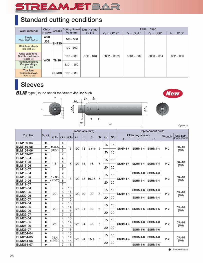
øDo øDi øDn L1 h b S1 S2 S3A B C
BLM159-04 15.875(.625")
4
15 100 15 15.875 515 15
SSHM4-4 SSHM4-4 SSHM4-4 P-2 CA-16(M6)
BLM159-05 5BLM159-06 6
20 20BLM159-07 7BLM16-04
16
4
15 100 15 16 515 15
SSHM4-4 SSHM4-4 SSHM4-4 P-2 CA-16(M6)
BLM16-05 5BLM16-06 6
20 20BLM16-07 7BLM19-04
19.05(.750")
4
18 100 18 19.05 515 15
SSHM4-4
SSHM4-6 SSHM4-6
P-2 CA-16(M6)
BLM19-05 5SSHM4-4 SSHM4-4BLM19-06 6
20 20BLM19-07 7BLM20-04
20
4 13
100 19 20 5 15 15
SSHM4-4SSHM4-6 SSHM4-6
P-2 CA-16(M6)
BLM20-05 5 14BLM20-06 6 15
20 20 SSHM4-4 SSHM4-4BLM20-07 7 16BLM22-04
22
4 13
125 21 22 515 15
SSHM4-4 SSHM4-6 SSHM4-6 P-2 CA-16(M6)
BLM22-05 5 14BLM22-06 6 15
20 20BLM22-07 7 16BLM25-04
25
4 13
125 24 25 515 15
SSHM4-4SSHM4-8 SSHM4-8
P-2 CA-16(M6)
BLM25-05 5 14BLM25-06 6 15
20 20BLM25-07 7 16 SSHM4-6 SSHM4-6BLM254-04
25.4(1.000")
4 13
125 24 25.4 515 15
SSHM4-4SSHM4-8 SSHM4-8
P-2 CA-16(M6)
BLM254-05 5 14BLM254-06 6 15
20 20BLM254-07 7 16 SSHM4-6 SSHM4-6
10 L1
h
b ØD
n
ØD
i
ØD
O
S1
A B C
S2 S3
New
Vc (sfm) ap (in) f (ipr)
rε = .0012" rε = .004" rε = .008" rε = .016"W08
J08SH730
160 - 500
.002 - .040 .0002 - .0008 .0004 - .002 .0008 - .004 .002 - .006
W08
100 - 500
TH10100 - 330
330 - 1650
SH730 100 - 330
Seal cap*(Inner screw)
*Optional
Cat. No. Stock
Dimensions (mm) Replacement partsClamping screws Wrench
SleevesBLM type (Round shank for Stream Jet Bar Mini)
� : Stocked items
Standard cutting conditions
Steels1008 - 1045 SAE etc.
Stainless steels303, 304 etc.
Gray cast ironsDuctile cast irons
No35B etc.Aluminum alloys
Copper alloysSi < 13%
Titanium Titanium alloys
Ti-6Al-4V etc.
Work material Chip-breaker Grades Cutting Speed Depth of cut Feed:

29
12
øD ød
b
h
25
16
øD
ø14
(10)
4-M6 (3-M6)
45
25
h
øD
4050
3010
R3/8
b
16
3-M6
b ød
øD 3-M5X0.8
h
12
ødøD
øD ød R h bBLM19-08
8
19.05100
1818
BLM20-08 20 19BLM22-08 22
12521 21
BLM254-08 25.4
24
24BLM25-08C
25 55 23BLM25-10C 10BLM25-12C 12
øD R1 R2 ødBLC32-8C 8
45 20 32BLC32-10C 10BLC32-12C 12BLC40-8C 8
55 13 40BLC40-10C 10BLC40-12C 12BLC40-16C 16
øD R1 R2 ødBLC40-8 8
73 13 40BLC40-10 10BLC40-12 12BLC40-16 16
øD R h bBLS16-08 8
125 28 12.5BLS16-10 10BLS16-12 12
øD R h b
BLS16-08C 8100 28 12.5BLS16-10C 10
BLS16-12C 12
BLC type (Short type)
BLS type (Square shank)
BLS-C type (Square shank)
BLM type (Round shank)
BLC type (Standard type)
Above drawing shows BLM25-**C type.
( ) is for BLS16-08
Applicable Dimensions (mm) Cat. No. Stock shank dia.
Flat
� : Stocked items
Applicable Dimensions (mm) Cat. No. Stock shank dia.
Applicable Dimensions (mm) Cat. No. Stock shank dia.
Applicable Dimensions (mm) Cat. No. Stock shank dia.
Applicable Dimensions (mm) Cat. No. Stock shank dia.

T U N G A LOY
30
A10-STUPR2.5-D14 A12M-SDUCR07-D160TPMT222-PS DCMT21.51-PS
T6030 GT730
390 560.006 .006
.004 - .118 .010
A10-SDQCR2-D14 A10-SCLPR3-D14DCMT21.52-PS CPMT322-PS
GH730 NS730
230 600.007 .006.008 .016
When competitor’s tools are used, inserts often fractured due to chip re-cutting and tool life is unstable. With excellent chip control, the Stream Jet Bar excels in chip control and eliminates unexpected insert breakage caused by chip re-cutting and delivers consistent tool life. The tool also disposes of chip tangling and gives outstanding chip evacuation when taper boring.
Competitor tools often showed unexpected fracture of the cutting edge and tool life was inconsistent. The Stream Jet Bar could suppress unexpected fracture and provide consistently long tool life.
Compared with the previously used competitor’s tool, the tool life was increased by 50 % and the surface fi nish was also improved. Even when machining the small diameter (ø17) portion, chip control was improved.
Competitor’s tooling often showed chips tangling around the toolholder resulting in the machine having to be stopped to remove chips. This drastically reduces productivity. The Stream Jet Bar suppressed chip tangling and prevented unnecessary machine stoppages. The productivity per hour was improved by 20 % from 500 pcs./H to 600 pcs./H.
Increased tool life andmachining stability
40 pcs.600 pcs./H
Competitor Competitor
Number of work-pieces machined:
Fractured
Fixed number
Productivity
20 ~ 40 pcs.500 pcs./H
20 % increased productivity
Machine parts
Automotive parts
Automotive parts
Automotive parts
wet (External supply)
Wet (Internal supply)
wet (Internal supply)
Wet (Internal supply)
Practical examples
Increased tool life and machining stability
150 pcs.Competitor
Number of work-pieces machined:
50 ~ 100 pcs.
50 % increased tool life
300 pcs.Competitor
Number of work-pieces machined:
200 pcs.
Work piece typeToolholder
InsertGrade
Work material
Cutting speed : Vc (sfm) Feed : f (ipr) Depth of cut : ap (in) Coolant
Results
Cut
ting
cond
itio
ns
304 1045
5120 4130
Work piece typeToolholder
InsertGrade
Work material
Cutting speed : Vc (sfm) Feed : f (ipr) Depth of cut : ap (in) Coolant
Results
Cut
ting
cond
itio
ns
1.6"
ø1"
1.6".3"
ø1.
1"ø
1.5"
ø.7
"
ø2.
4"
ø1.
4"ø
1.2"
ø1.
6"ø
2"
1.25" .8"
ø2.
4"
ø.8
"

31
A08-STUPR2-D11 E12-SDUCR3-D16TPMT221-PM DCMT32.51-PS
GH730 T9115
720 230 - 520.008 .005 - .008.020 .040
E08-SCLCR2-D11 E12-SDUCR3-D16CCMT21.52-PM 2QP-DCGW32.51
T9125 BXM10
660 660.012 .002.040 .003
30°
Vc = 720 sfmVc = 590 sfm
Previously the cutting speed was limited to 590 sfm to suppress chatter. When using the Stream Jet Bar, chatter did not occur at speeds up to 720 sfm and the surface fi nish after machining the same number of parts was superior to those obtained with previous tools. The dimensional accuracy of the machined bore was also improved.
When using a competitor’s tool, roughing and medium fi nishing processes were needed to machine this component. The high level of rigidity with the Stream Jet Bar allowed one-pass machining. Chip control and surface fi nish were also improved.
Compared with a competitor chipbreaker tool for medium cutting, the PS-type chipbreaker improved chip control. Under stable machining, the Stream Jet Bar improved chip evacuation and eliminated insert fracturing caused by chip re-cutting. The result is improved tool life and surface fi nish.
By switching from internal grinding, the productivity was increased due to the shortened machining process.In addition, the machining costs could be reduced by eliminating the grinding-sludge disposal cost.
Automotive parts
Automotive parts
Machine parts
Automotive parts
Wet (External supply)
Wet (External supply)
Wet (Internal supply)
Dry
Increased cutting speeds(Produetivity increased 20 %)
Competitor
Number of work-pieces machined / H
67 % increased tool life
100 pcs.Competitor 60 pcs.
Number of work-pieces machined:
Twice the productivity
One pass
Competitor Two pass
Number of work-pieces machined:
1025
1045
1035
1045
Work piece typeToolholder
InsertGrade
Work material
Cutting speed : Vc (sfm) Feed : f (ipr) Depth of cut : ap (in) Coolant
Results
Cut
ting
cond
itio
ns
Work piece typeToolholder
InsertGrade
Work material
Cutting speed : Vc (sfm) Feed : f (ipr) Depth of cut : ap (in) Coolant
Results
Cut
ting
cond
itio
ns
ø1.
5"ø
1"
1.5"
ø1.
25"
ø2.
4"
3.4"
ø1.
6"
ø.7
"ø
1.26
"
1.2" 1.2"
ø1"

Distributed by:
Oct. 2013 (TA)
3726 N Ventura Drive, Arlington Heights, IL 60004, U.S.A.Inside Sales: +1-888-554-8394Technical Support: +1-888-554-8391 Fax: +1-888-554-8392
Tungaloy Canada432 Elgin St. Unit 3, Brantford, Ontario N3S 7P7, CanadaPhone: +1-519-758-5779 Fax: +1-519-758-5791
Tungaloy de Mexico S.A.C Los Arellano 113, Parque Industrial Siglo XXIAguascalientes, AGS, Mexico 20290Phone:+52-449-929-5410 Fax:+52-449-929-5411
www.tungaloyamerica.com
Become a fan on facebook
Follow us on Twitter @tungaloy
Watch our videos on You Tube
Scan for instant web access