Highly-Efficient Multi-Coil Wireless Power Transfer … 1 Mehdi Kiani GT-Bionics Lab, School of...
22
www.GTBionics.org 1 Mehdi Kiani GT-Bionics Lab, School of Electrical and Computer Engineering Georgia Institute of Technology, Atlanta, GA Highly-Efficient Multi-Coil Wireless Power Transfer (WPT) May 31, 2014
-
Upload
hoangkhuong -
Category
Documents
-
view
212 -
download
0
Transcript of Highly-Efficient Multi-Coil Wireless Power Transfer … 1 Mehdi Kiani GT-Bionics Lab, School of...

www.GTBionics.org 1
Mehdi Kiani
GT-Bionics Lab, School of Electrical and Computer Engineering
Georgia Institute of Technology, Atlanta, GA
Highly-Efficient Multi-Coil Wireless
Power Transfer
(WPT)
May 31, 2014

www.GTBionics.org 2
WPT Applications
2
Charging mobile electronics Implantable Medical Devices
(IMDs)
Charging electric cars
RFID

www.GTBionics.org 3
Coupled-mode Magnetic Resonance-based Power Transmission
A. Kurs, et. al, Science 2007
• Proposed by physicists at MIT based on coupled-mode theory (CMT)
• An alternative wireless power-transfer technique using typically four coils
• Goal: Increase the power transfer efficiency (PTE) at large coupling distances
60-W is
transferred
from 2-m
away

www.GTBionics.org 4
Questions?
• A need for a comprehensive circuit theory for coupled-mode magnetic resonance-based links
• A need for circuit theory based on the reflected-load theory (RLT) for multi-coil links
• Are coupled-mode magnetic resonance-based links always the optimal choice?
• A need for a new figure-of-merit (FoM) for high performance multi-coil design
vs.
Resonant-magnetic coupling Inductive coupling
www.GTBionics.org 5
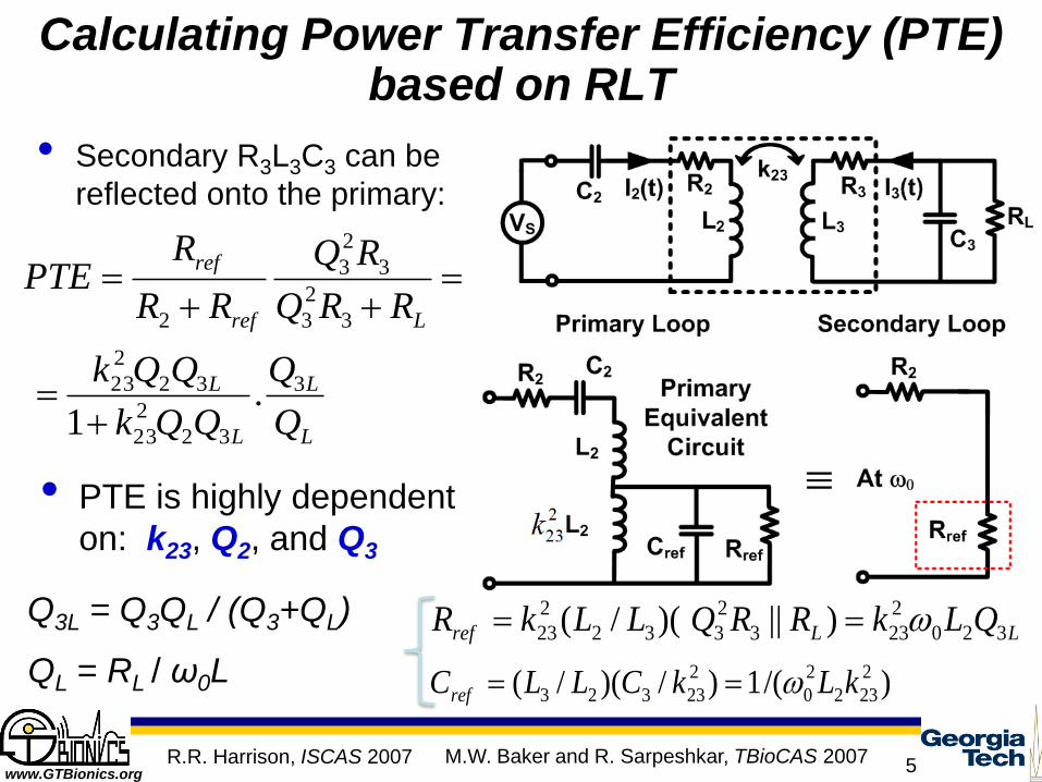
Calculating Power Transfer Efficiency (PTE) based on RLT
• PTE is highly dependent
on: k23, Q2, and Q3
• Secondary R3L3C3 can be
reflected onto the primary:
LLref QLkRR QLLkR 320
2
233
2
332
2
23 )||)(/(
)/(1)/)(/( 2
232
2
0
2
23323 kLkCLLCref
Q3L = Q3QL / (Q3+QL)
R.R. Harrison, ISCAS 2007
Lref
ref
RRQ
RQ
RR
RPTE
3
2
3
3
2
3
2
L
L
L
L
Q
Q
QQk
QQk 3
32
2
23
32
2
23 .1
QL = RL / ω0L
M.W. Baker and R. Sarpeshkar, TBioCAS 2007
www.GTBionics.org 6
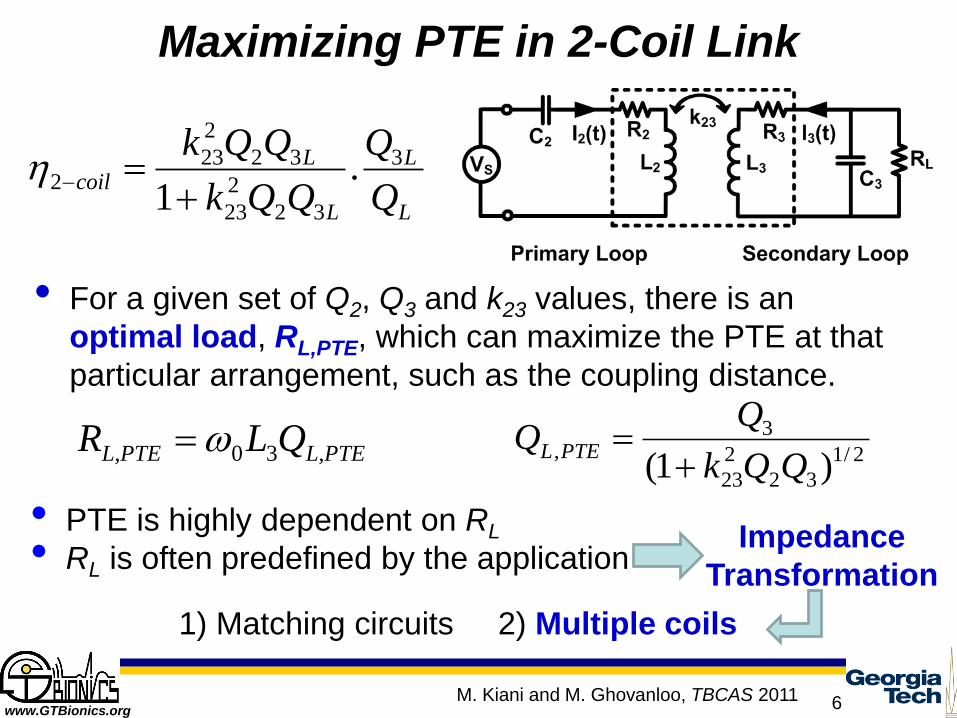
Maximizing PTE in 2-Coil Link
• PTE is highly dependent on RL
• RL is often predefined by the application
Impedance
Transformation
1) Matching circuits 2) Multiple coils
L
L
L
Lcoil
Q
Q
QQk
QQk 3
32
2
23
32
2
232 .
1
2/1
32
2
23
3,
)1( QQk
QQ PTEL
• For a given set of Q2, Q3 and k23 values, there is an
optimal load, RL,PTE, which can maximize the PTE at that
particular arrangement, such as the coupling distance.
L,PTEL,PTE QLR 30
M. Kiani and M. Ghovanloo, TBCAS 2011

www.GTBionics.org 7
PTE and Delivered Power (PDL) in Multi-coil Inductive Links based on RLT
)/( 1,0 iirefiiiL RRLQ
• In an m-coil link with negligible coupling between non-
neighboring coils
Rref from (i+1)th coil to the ith coil:
Loaded Q of the ith coil:
PTE between ith and (i+1)th coils:
m-coil link PTE:
PDL:
Four-coil link (m = 4)
Liiiiiiref QLkR )1(0
2
1,1,
)/( 1,1,1, iirefiiirefii RRR
LmL
m
i
iicoilm QQ /1
1
1,
mLmL L = RQ 0/ LmmL RL = Q /0
coilm
L
scoilmL
QQkR
VP
21
2
121
2
,1
1
2
Parallel load: Series load:
M. Kiani and M. Ghovanloo, TBCAS 2011

www.GTBionics.org 8
PTE in Multi-coil Inductive Links based on CMT
• In m-capacitively loaded resonators:
Four-coil link (m = 4)
Resonance width:
)()()()()(
212111 tFtajKtajdt
tdaS
)()()()(
1,1 tajKtajdt
tdammmmLm
m
)()()()()(
11,1,1 tajKtajKtajdt
tdaiiiiiiii
i
21
1
m
i m
iiLm
L
S
Lcoilm
A
AP
P
tj
ii eAta 0)(
22 iii AP
ii Q2/0
Coupling rate: 2/1,01, iiii kK
PTE from CMT is identical to the one from RLT!
M. Kiani and M. Ghovanloo, TCAS-I 2012

www.GTBionics.org 9
Resonant Magnetic Coupling vs. Inductive Coupling (Transient)
CMT transient response is accurate when
coils coupling is weak and coils quality
factor is very high!
1) Mid-range high-Q condition 2) Short-range low-Q condition
M. Kiani and M. Ghovanloo, TCAS-I 2012

www.GTBionics.org 10
3-Coil Inductive Link
• L3-L4 inductive link provides designers with a DoF (M34) to adjust the reflected load on to L3 to be the optimal value: RL,PTE
• Loosely coupled L2-L3 link is designed for optimal RL,PTE
• Inductive link optimization is decoupled from RL
• L3-L4 inductive link PTE is high as their coupling distance is small
L,PTEL,PTE QLR 30 2/1
32
2
23
3,
)1( QQk
QQ PTEL
L
L
LL
Lcoil
Q
Q
QQkQQkQQk
QQkQQk 4
43
2
3443
2
3432
2
23
43
2
3432
2
2334233 .
)]1)(1[(
))((
L2
L3
L4
M. Kiani and M. Ghovanloo, TBCAS 2011

www.GTBionics.org 11
Maximizing PTE in the 3-Coil Link
By changing k34
(and Rref,3), the
3-coil PTE can be
kept at maximum
for a wide range
of RL.
A 2-coil link does not provide this flexibility, and PTE maximizes
only for a specific RL value.
M. Kiani and M. Ghovanloo, TBCAS 2011
www.GTBionics.org 12
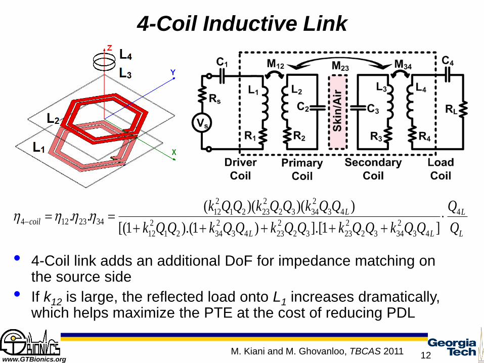
4-Coil Inductive Link
• 4-Coil link adds an additional DoF for impedance matching on the source side
• If k12 is large, the reflected load onto L1 increases dramatically, which helps maximize the PTE at the cost of reducing PDL
L
L
LL
Lcoil
Q
Q
QQkQQkQQkQQkQQk
QQkQQkQQk 4
43
2
3432
2
2332
2
2343
2
3421
2
12
43
2
3432
2
2321
2
123423124
]1].[)1).(1[(
))()((..
M. Kiani and M. Ghovanloo, TBCAS 2011

www.GTBionics.org 13
PTE and PDL in 3-Coil Link
Maximizing PTE should
not be at the cost of
decreasing PDL
L
L
L
LscoilL
Q
Q
QQkQQk
QQkQQk
R
VP 4
2
43
2
3432
2
23
43
2
3432
2
23
2
2
3,)1(
))((
2
2/1
32
43
2
34,23
1
QQkk L
PDL
2/1
43
32
2
23,34
1
L
PDLQQ
QQkk
The optimal design maximizes
both PTE and PDL
M. Kiani and M. Ghovanloo, TBCAS 2011
www.GTBionics.org 14
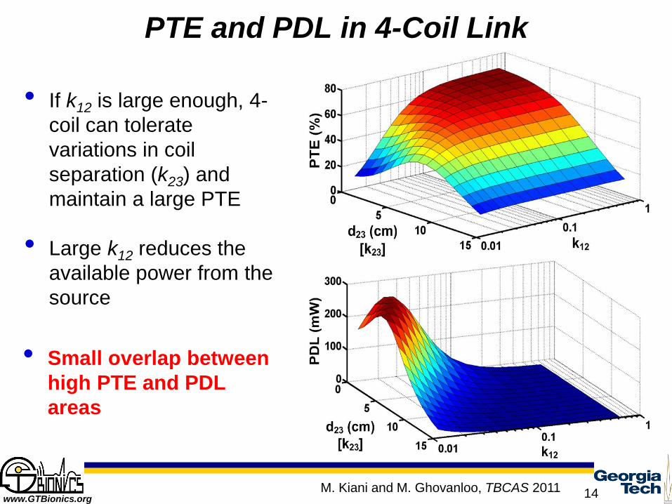
PTE and PDL in 4-Coil Link
• If k12 is large enough, 4-
coil can tolerate
variations in coil
separation (k23) and
maintain a large PTE
• Large k12 reduces the
available power from the
source
• Small overlap between
high PTE and PDL
areas
M. Kiani and M. Ghovanloo, TBCAS 2011
www.GTBionics.org 15
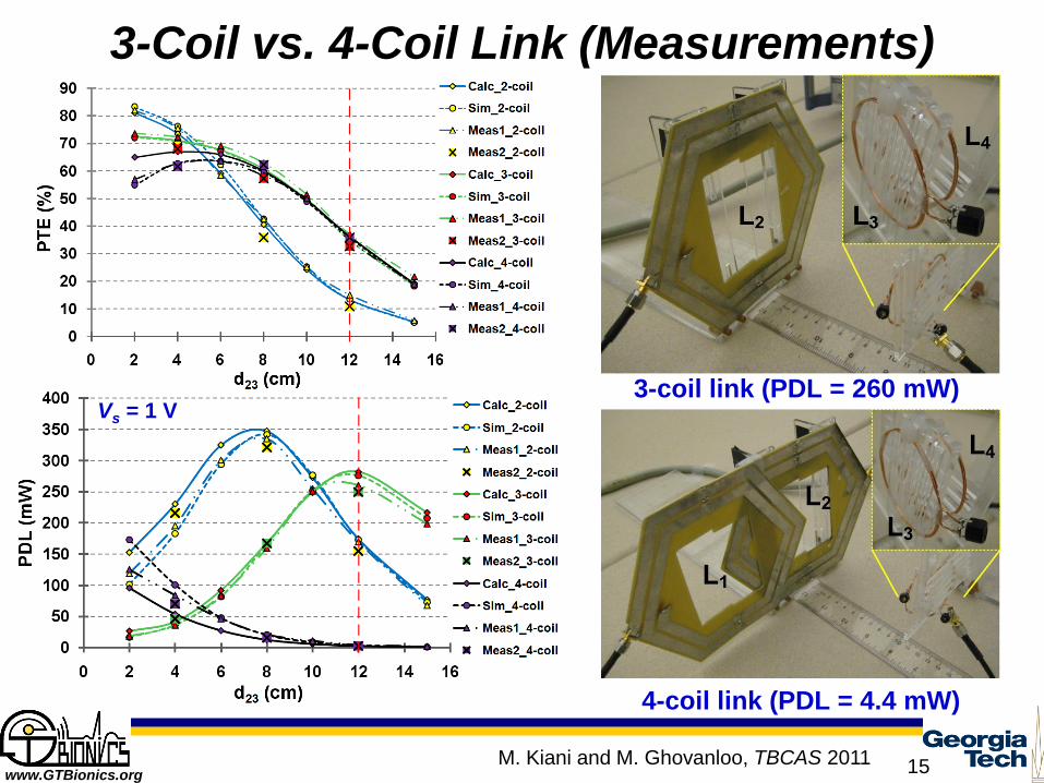
3-Coil vs. 4-Coil Link (Measurements)
4-coil link (PDL = 4.4 mW)
3-coil link (PDL = 260 mW) Vs = 1 V
M. Kiani and M. Ghovanloo, TBCAS 2011

www.GTBionics.org 16
Resonant-Magnetic Coupling vs. Inductive Coupling (PTE)
Calculated PTEs were similar from CMT and RLT and matched very
well with measurements!
Four-coil link measurement
setup. Three and two-coil
links used similar coils except
L1 and L4, respectively.
M. Kiani and M. Ghovanloo, TCAS-I 2012

www.GTBionics.org 17
A New Figure of Merit (FoM) for Inductive Power Transmission
• Conventional design merits are either PTE or PDL
• How to balance PTE and PDL?
• How to choose between 2-, 3-, and 4-coil links?
2
,
s
coilmL
n
coilm
V
PFoM
n: PTE weight, which
depends on the application
• FoM effect on PTE and PDL drop:
max,max , LP
: FoM is maximized FoMLFoM P ,,2
2
max,
,max,
,
max
max
)2(
,2
1
n
n
P
PPP
n
L
FoMLL
LossL
FoMLoss
: PTE and PDL are
maximized
M. Kiani and M. Ghovanloo, TIE 2013
www.GTBionics.org 18
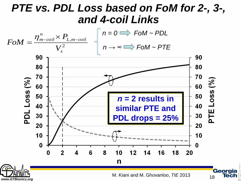
PTE vs. PDL Loss based on FoM for 2-, 3-, and 4-coil Links
n = 2 results in
similar PTE and
PDL drops = 25%
2
,
s
coilmL
n
coilm
V
PFoM
n = 0 FoM ~ PDL
n → ∞ FoM ~ PTE
M. Kiani and M. Ghovanloo, TIE 2013

www.GTBionics.org 19
Optimal 2-coil Link for IMDs based on FoM
• 2-coil Link for
IMDs
• Rx coil dia. =
10 mm
• Vs = 1 V
• Rs = 0.5 Ω
• RL = 100 Ω
• f0 = 13.56 MHz
• d23 = 10 mm
At d23 = 10 mm, FoM-optimized link provides 47% more PTE than the PDL-optimized link and 16 times larger PDL than the PTE-optimized link.
M. Kiani and M. Ghovanloo, TIE 2013

www.GTBionics.org 20
Comparing 2- 3- & 4-Coil Links for IMDs
• At d23 = 10 mm, 4-coil link provides 4.9% more PTE and 11 times less PDL than an equivalent 3-coil. At d23 = 20 mm, PTE difference is 7.7%, while PTE of 3-coil is 192 times larger than an equivalent 4-coil
• For large Rs, 4-coil is optimal
An FoM including both PTE and PDL is needed to differentiate between 2-,3-, and 4-coil links!
M. Kiani and M. Ghovanloo, TIE 2013
www.GTBionics.org 21
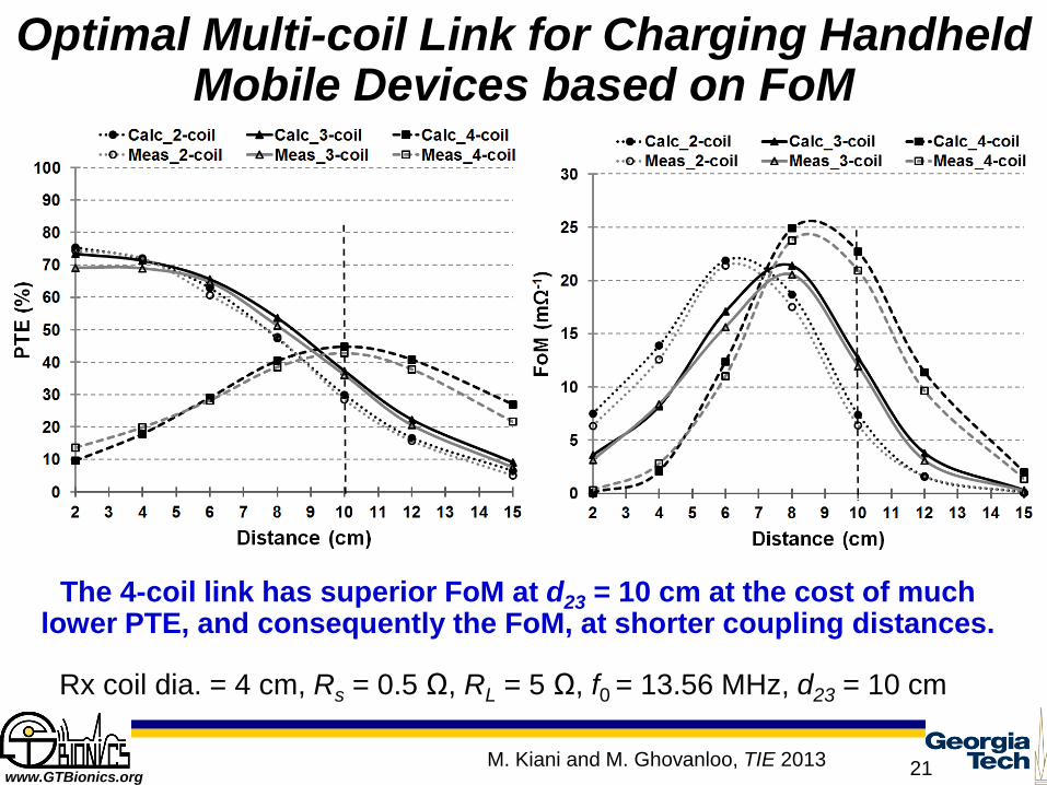
Optimal Multi-coil Link for Charging Handheld Mobile Devices based on FoM
Rx coil dia. = 4 cm, Rs = 0.5 Ω, RL = 5 Ω, f0 = 13.56 MHz, d23 = 10 cm
The 4-coil link has superior FoM at d23 = 10 cm at the cost of much lower PTE, and consequently the FoM, at shorter coupling distances.
M. Kiani and M. Ghovanloo, TIE 2013

www.GTBionics.org 22
Optimal Multi-coil Link based on FoM
2-Coil Link 3-Coil Link 4-Coil Link
Strong coupling (k)
Weak coupling (k)
Large PDL (small Rs)
Small PDL (large Rs)
Coupling variations &
small Rs
Coupling variations &
large Rs
M. Kiani and M. Ghovanloo, TIE 2013