Higher Olefin Process Esso - TU Delft
19
Delft Tech __ • Higher Olefin Process Esso Design group: CPD 3241 M. M. Dessens Julianalaan 49 2628 BC Delft 015-2130767 C. van Pijpen Achterom 153 2611 PN Delft 015-2147059 Basis of Design R. van de Klundert Hendrik Tollensstraat 348 2624 BV Delft 015-2510029 G.J. Schoof Oost-Indiëplaats 39 2611 BS Delft 015-2123444
Transcript of Higher Olefin Process Esso - TU Delft

Delft Tech '_..,oI~d __ •
Higher Olefin Process Esso
Design group: CPD 3241
M. M. Dessens Julianalaan 49 2628 BC Delft 015-2130767
C. van Pijpen Achterom 153 2611 PN Delft 015-2147059
Basis of Design
R. van de Klundert Hendrik Tollensstraat 348 2624 BV Delft 015-2510029
G.J. Schoof Oost-Indiëplaats 39 2611 BS Delft 015-2123444

€~ Delft Tech ,._""",ol~_1
Table of contents
1. DESCRIPTION OF THE DESIGN ............................................................. 3
2. PROCESS DEFINITION ........................................................................... 4
2.1 PROCESS CONCEPT CHOSEN .............................................................. . ............. 4 2.1.1 Debutanizer .............. .. ....... ...... .. ............ .............. ... .... ...... ............. .. ..... .. . 4 2.1.2 Separation .................... .. ... ........ ............ ................ .. .... .......... ........ .. ........ 4 2. 1.3 Higher o/erin production .......... .......... .......... ........... .. ....... ......................... 5
2.2 BLOCK SCHEMES ............ .... ........ . ......................... .... ..... ... .............. . ....... .......... 8 2.3 THERMODYNAMIC PROPERTIES .. .. ................... ...... . ............................. ........ ... .. . 9 2.4 LIST OF PURE COMPONENT PROPERTIES ................ ........ .. ................................ 10 2.5 PROCESS STREAM SUMMARY AND MASS BALANCES ................................... ....... 11
3. BASIC ASSUMPTIONS .......................................................................... 12
3.1 FEEDSTOCKS ............. .. ...... . ........................................................................... 12 3.1.1 Feed T-6304 ........ ...................... ....... ........ ... ................. ............ ............. 12 3.1.2 Anthracene ........ ........... ... ........... .. .... ..... ...... ................................ .......... 12 3.1.3 Chemica/ grade ethy/ene ............ .. ......... ... ... ................................ ..... ... .. 13
3.2 PRODUCTS ........................... .. ................................................................. ...... 13 3.2. 1 A/pha o/erin product...... ........................ .. .......... .. .. .......... .............. .. ...... . 13 3.2.2 Bottom product T-6304 ........... ... ........... ........ .. ............. ..... ........... .... .. .... 14 3.2.3 Paraffin extract........................... .. ....... .... .. ... ..... ...... ................. ............ . 14
3.3 PLANT CAPACITY ....... .. ....... . ........ .. ...... ............. ... ........ ......... ... .. ..................... 14 3.4 CATALYST SPECIFICATIONS ................................... . .. . .. ..... ... ............ . ..... . ........ 15
4. ECONOMIC POTENT lAL ....................................................................... 16
5. LITERATURE ......................................................................................... 18
Table of contents

e~ Delft Tech _"'" ol AptIIIIItI _<"<lil'
1. Description of the Design
Exxon's Flexicoking process upgrades vacuum residue oil ancYsPlits~into Gas, LPG, Naphtha over the top, Light Koking Gas,oil (LKGO) as a side s~~ Koking Gas Oil (HKGO) over the bottom. The said top stream is passed through a desulfurizing step and then through a deethanizer and debutanizer sequentially. The deethanizèr withdraws C1-C2
hydrocarbons from this strs:am (which are sold to the Gasunie). The debutanizer splits this stream into LPG (C3-C4) over the top and naphtha · over the bottom. The subject of this assignment lies in the top stream of the Flexicoking proçes.s, especially in ~eam ellfering c:;-{ the debutanizer. . ~
This stream cöntains about 160 components, some known and some unknçwn. The typical value of this ~ream, which aftersome steps. ends up as. fueI oil, is 100-150 $/ton. The naphtha, however, contains a-olefins which have a value of J 000-1500 $/ton . and find themselves in a growing market [1], so there ~s some profit to be expected when these materials can be isolated. FUrtherll!ore, the a-olefins can be used together with the internal olefins, also present ip. the naphtha, to produce detergent intermediat~s for the soap in'<Îustry, with a price range of about 1500-2000 $/ton. We chose detergent intermediates becal;lse this product has.many applicatio~re a larger market compared to end products such as alcohols (surfactants) and acids (detergents).
ft is the object of this design to separate all the linear olefins from the naphtha and us(! these components as r;eactaf!!.s in a process (0 upgrade these olefins !rom the C3-C6 range to the Ç,JO-CI6 range, às commonly used in detergent, wirhin the economical wTndà7v- proviàe,d by Exxon . .
The design, which will be done in ChemCAD 111, starts with modeling the stream of naphtha through IUIl!PmgcomQ..onents (s~e paragraph 2.4 and 3.1.1). Then, attent ion will be given to the operating conditions of the debutanizer, . already present in the current process (see paragraph 2.1.1). From there on tl}e modeling of frrst the sèparation and later on the reaction starts. The dèsign will be concluded by integrating the entire process' and calculating the economics that co me along with the prpcess. ' .
The design can be evaluated at two points: after the se.paration and after tQe .l.~Eion. In both cases an evaluation will be made of the profits (this is because the products from both the separation and reaction have a profitabIe market). 0 ,
{L,~..(
t-?~ f~ ~,ltJ.~ Il ~.~
Description ofthe design

€S~ 2. Process definition
The design consists ofthree stages: a debutanizer, a separation section and a reaction section . These stages are outlined in the following paragraphs.
2.1 Process concept chosen Due to the large streams (1..0-70 tonslhr), it is more favorable to operate the process continuously.
2.1.1 Debutanizer Because ofthe need ofC3-C6 olefinsJn maJ}.ufaçturing detergents by oligomerization, the light ends ofthe bottom stream (C5-C6) hav.e to be combined with 'the ~op stream (C3-C4). This can be done by choosing' ~ lower reflu~ ratio for the debutanizer and a highe~ operating \) temperature by simply increasing tbe MPA (methyl propyJ amine2..ft~ctionator ..streaw. The ( MPA fractionator is responsibJe for the heat duty in the reboiler. Another advantage is that the ~ heavy ends can continue their normal route through the process. This however at the cost of higher MP A fractionator costs. '
2.1.2 Separation The object of the separation is to obtain u- and intemal oJefins with the highest possible recovery and purity. To accompJish this, the said components have to be withdrawn from a stream containing paraffins (branched and linear), branched olefins and ar~. This can . ---. . ~~
be done by separating the ~ed l!q!!l the ]ne'lf hydrocarbons, to improve yields and ? recoveries in the ~ain step: complexation of olefins ina mixtur~ wi!~ ~~ms. '2-:> ~c4.
;x::;c:::c:= ~ • Sepa'rating ~ hydrocarbons can be done in two ways: ~ _ _ cy._:...-_---
...} (+) '> (+)
----? ~ (+) -:;:. (-)
::> (-)
-s» (-) ~ ) (-)
:> (+) .:::> (+) > (+) > (+)
--"'>'''!>' ) (-) -~~ )(-!
Simulated Moving Bed operation [2,3] Use of zeolites in a con.!inuous way High recovery and purity ~n branched/unbra~ched hydrocarbons Proveri ind~~trial success (Molex, Olex) , Need of a.desorbent Comp!i!?at~d c~~tru9ti9n (because of altemating feed and withdrawal points in the column) ) Difficult to model Exp~nSive (es~m~ted at 120 millio~$ oftotal capital investment)
Zeolitic membrane [4,5,6]
There are many types of zeolites suitable for this separation [7], with relativeJy smaU differences in price and performance. Unforh;lnately b'oth opti.~ns are not suitable for our purposes. The fust because of the ~ especiaUy . wheri put in . perspeètive with our economical margjn, the second because of the low capaci!y. This means that there can be l?2 pre-treat~nt ofthe stream prior to complexation. ;; p -
L.) =- .jt,,,l. ~ 4 0
Process definition 4

~~~ Is'?
Delft Tech ~3_~_ ~ Fo~xa~ have two alternatives: /LettIJ./.O--..~ .
,1UIty ol AppIot' .........
" \\~~~ . Complexation through reactlo °111 CU(,I-Sa,f3....---...,
~ (+) Quick reactions 7 /> (+) Easy separation fro~eacted aterials (solids) '> (-) DifficuIt regeneratioir--·:_·.......,..... ;> (-) Envir~nmenial restrictions
~~.~ f) ~~ .
--7 > (-) Decreasing selectiyity with in~reasing c~rb~n num~er, starting at ethyl~e (-) Solid handling , ,
-;) :;> (+) -? >(+)
> (+) :>(+)
~:> (+) > (-) ~ (-)
yomplexation through Diels-Alder rea~tion with anthracene [11,12,13] High se\ectivities, also for ,C5-Cg
High s~lectivity in branched ~ver unbranched Easy separation from unreacted materials Easy regeneration 9 Ea~y ~ep.aration afte~ regeneration ~ Environmental restrictions
~omplexation in re~",:~) salts ' c-.:::..:::.:.:...r . .' .~ • ~ ---2i
In spite of slightly sIowér reactions, complexatio,n with anthracenets favored, ecause the Diels-Alder, reac~ion is an equilibrium reaction (fITst order in both~~.E!.~~ ond order overall), the pest thing to do is to bring the anthrace",e stream in count~rcurrent contact with the olefiris ~eam at a 'te~pçrature at which the olefin ,stream is gase9l!S and t nthrac estream is liquid, e,g. somewhere between 240 a~d 280°C (at a 'pressure ,ofÎ3 barl,. At each stage equilibrium is assumed and so we can açhieve/ high recQveries. No c~eeded for this"Ieaction. Assumptions on kinetics will be ~de on the basis of [11,12,13]. The ol~fins will be Iumped.into certain categorie!; and each category will ~e given a certain k-value, ,e.g. Ci-a, Ci-internals, branched. . After this, the equilibrium has to be reversed, choosing appropriate conditi~ns (high(er) temperatlire and low(er) pressure). and the olefins have to be separated from the anthracene (large difference in boiling points) by simp Ie distilIi:ttion. It is still not certain whether this can be done in Qne UnitOp or not. The anthracene can be recycIed and we now hav~ a stream of pure olefins (a, internal anda negligibie amount ofbranched). ' :i::::: c:::
2.1.3 Higher olefin production To produce the required C IO-C I6 .a-oIefms, inJhis reaction section we are going to make use of a combination of oligomerization. metathesis apd isomerizatiQn. One ind~strial éxample Of9~this process is the SHOP (Shell Higher Olefin Proeess) [1«,15]. Based on this SHOP, trhr alternative~ cam:e up. !her are called "a~te:I SlJ2.P", "ethy.!.en~!!l.sPztttJ?n" . d :s X "low~.fI~I~~nzatIon". ' First the thiëê different reactions are ~xplained, after which the three alternative processes are discussed. ' .
Reactions
• Oligomerization Small and intermediate molecules are connected to each other to fQ.(Jl1 large molecules. ~ oligomerization yields a-olefi'!1s in the rang~~~hè length ,of tbe produced chain varies with the' reaction ~ime. The shorter the reac IOn .lme, the smaller the p.Toduced chain. The ~t used is [PhC(NSiMe3)2hCrCI [16]. The kinetics are determined on basis of [16], in wlifcIlConversion and" product~ distribution of ethylene a~e given. The kinetics of the whole l feed range are assumed on the latler data.'
Process definition 5

. (!:- -:; C ) ~~ ~ ~ "' Del e c:: -== c Tech • Metathesis / / Two double bond mol~cules co_nnect and d'sco _ ct with th 1f ouble .RO~. The two chains have now swapped their alkyl groups. So RI=~f + R~=~ RI R3 + !tt J3..2. etathesis with ethylene yields .a-ol~fms. The cllêl~t used is R~Ûïon-A 2 • 3 [14, 17-2 . The kinetics are mainly based on [22J. References [16-22J are used to extrapolate and adjust the different data and provide a good base for the necessary assuUlptions. '
• Isomerization In tbis case we mean double-bond isomerization. The double bond shifts in the mplecule. For instance isomerization of l-pent~ne yi~lds a mixture of l-pentene, . 2-pentene and 3-pentene. The catalyst used will be one of H3PWJ2Û40 and (NH4)3PW12Û~O [24J. For both catalysts data on reaction time, conversion and product distribution on C6-CS are available. Again the known data will b~ used to determine the kinetics for the broader feecj. range.
Alternatives 6. \C )
• Adapted SHOP (see figure 2.1) feed with the C3-C9 recycle from the separator IS Isomerize and subJected to
etathes' in 0 . This yields a range of internal olefins r 16. These are again s a tot etatliesi with the isomerized recycle from the bort,om 'of the separator and the ethylene recy larter is mixed with fresh ethylene. ~o ' get all the input ' reacted, the molar ratio olefins: ethylene has to be at least 1:8 and preferably 1:15. The so formed uolefins (range C2-C30) are the feed of a separator Wliich leads the ethyleiiè over th~ tçp, the C3-C9 near the top, the product in the midclle (CW-CI6) and the heavy fractions over the bortom (C I6+).
I ~ ~! e
fr .. hlf\ene hene rec.yd. ~ - l
I somerizEfionl OspropaJionallon c:lsprop<M1ion!lion +. ~7"~· .
~eem.lo1efiM Separator (C.-c..l
Otelinshom
It.«:~ .. _'" 1I8 .... ~S
~~ ~ (Crc,.?l
t1 cr (1!9 Intlm.1
• ..,. ... (c,,+l
I sorneriz!lion
H,PO. on-cl .... High9l'o-oIe~s
i....- (c,.+l
4t Fig 2.1: Adapted SHOP process
In general: (+) Mainly u-olefins are produced (-) Very 1~~Jj~ld in required product (-) ormous recycles . àted 50 to 1 00 tim~s the amount of feed (-) Need offresh ethylerie
Process definition 6
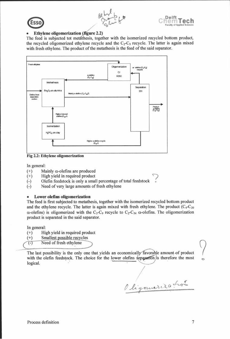
e @!~t? c ~~ I~~~ • Ethylene oligomerization '~2.2) The feed is subjected tot me~~etogether with the isomerized recycled bottom product, the recycled oligomerized ethylene recycle and the Cr C9 recycle. The latter is again mixed with fresh ethylene. The product ofthe metathesis is the feed ofthe said separator.
.. Fr.ah lthyIIM
m!Jllllerizstion ... -.(c,col 'ocyclo
Cr
l 0-.'" R202 (C,-C.,)
Me!halhesis
SeparaliOll
Re,o,..on-arumina 201 OIein,from ""'" OI-oI • .,s (C.· C,.1) s.rllton
"",""n
PIoduct
~~~ HigherinlellMl-ol8finl(C.+)
IsomeriZation
Hf'O.-m.dai
t KghM 0-0W .. 5 recycle (C,.'l
Fig 2.2: Ethylene oligomerization
In general: (+) Mainly a-olefins are produced (+) High yield in required product I (-) Olefin feedstoc~ is only a small percentage of total feedstock (-) Need ofvery, large amou~ts Qffresh ethylene
• Lower olefins oligomerization The feed is fust subjected to metathesis, together with the isomerized recycled bottom product and the ethylene recycle. The latter is again mixed with fresh ethylene. The product (C4-C20
a-olefins) is oligomerized with the C3-C9 recycle to Cr C54 a-olefins. The oligomerization product is separated in the said separator.
In general: (+) High yield in required product (+) Sma~~s.ihku:~~s
C?._~_~~f fresh .~h~~e~ ._ ... --The last possibility is the only on~ that yields an economicalL avora e amount..()f product with the olefin feeds~ock. The choice for the lower olefms ep~ is therefo~e the most logica\. -' -,' ' , '
/ ~.e..'~l;~a.~
Process definition 7

(,'\ 0 'f>
2.2 Block schemes
Oe6nrich slream (102)
F •• d(101)
D ebutanizer
T~304
Napbta (103)
Fig. 2.3: Separation step
Fresh ethylene (210)
Metatllesis
Jw. andbraoched olefin. (105)
Anthracene (104)
Counw
eurrellt
Contacling
Tower crI)
Anthracene compla (106)
Sep .... tor
(SI)
Anlhracen. bi eed (110)
------_.-----~~
01- ollfins (C,.C,) ,ec)'Cl. (207)
R~o,-on-atumina Malnlr ..... fin. (C.-
Oletinafmm
s~~~ sedlonT1
C,,?) r;2(2) ,--__ --1.. __ ---,
at 323 K 9 bar
Higher inlernlloltfin. (C,..) (209)
Isomerizatioo
H,PW'204Q of
(NH.)PW'204Q
s: 323 K 1 Bar
R203
cocatalyst: Li[PhqNSiMe,)']
at348K 13-41 bar
R202
CataI!" recycle (205)
Higher o-oleflnS recycle (C.+) (D)
C Delft Tech , . of AppIed __ I
Bhylene .. cycIe (2(6)
Separatioo
T201
Product mainly
1t~~8~, (211)
Fig. 2.4: l!çaeûon step. The olefin stre (stream 109)
the out-going stream of the separ~tion section
Process defmition 8
C Delft Tech 1' • ..," ApfIIIH a_i
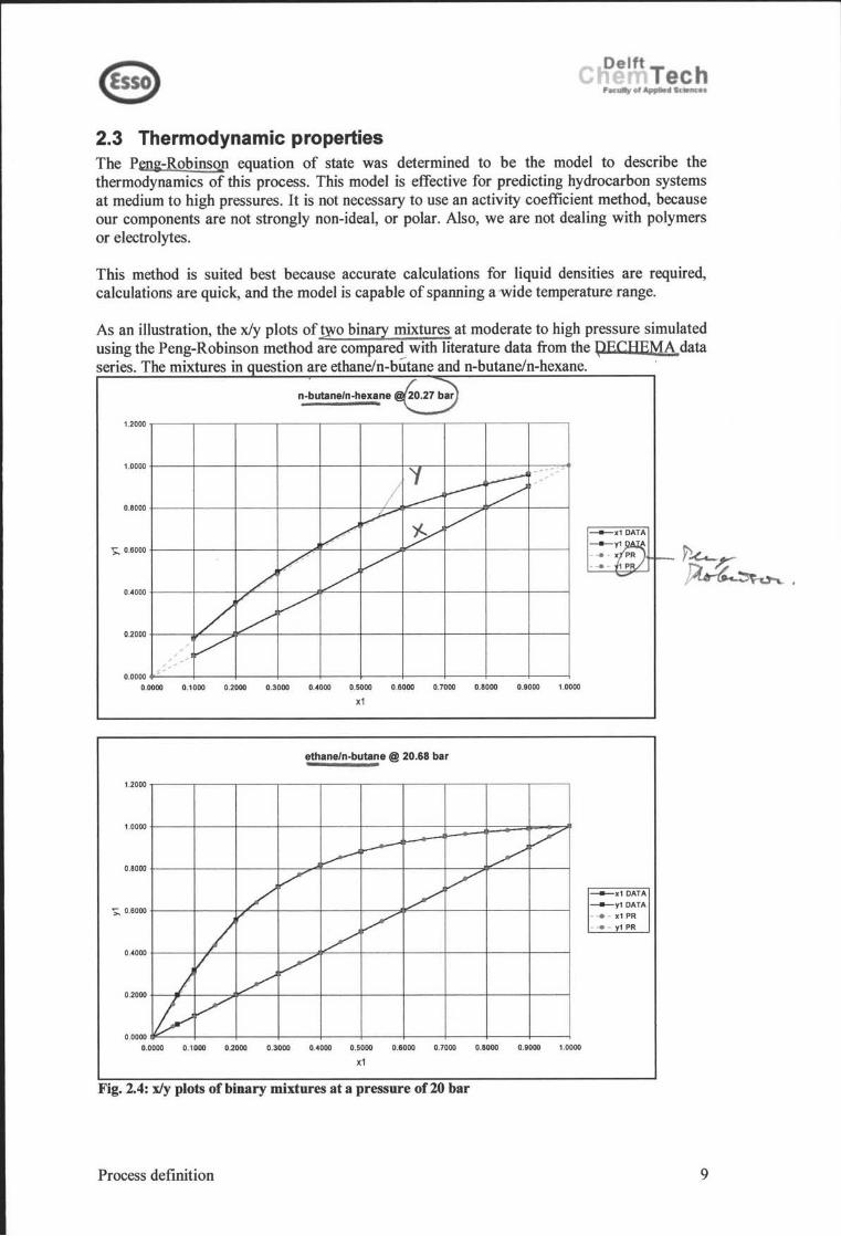
2.3 Thermodynamic properties Tbe P",ng-RobinsQ.n equation of state was determined to be tbe model to describe tbe thermodynamics of this process. This model is effective for predicting hydrocarbon systems at medium to high pressures. It is not necessary to use an activity coefficient method, because our components are not strongly non-ideal, or polar. AIso, we are not dealing with polymers or electrolytes.
This metbod is suited best because accurate calculations for liquid densities are required, calculations are quick, and the model is capable of spanning a wide temperatur.e range.
As an illustration, the x/y plots of jFo binary mixtures at moderate to high pressure simulated using tbe Peng-Robinson method are compared with literature data from tbe ~ECHEMA data series. Tbe mixtures in uestion are ethane/n-bûtane and n-butane/n-bexane. .
n-butane/n-hexane
1.2000
'I -~-.-
~ , ,
I ----~ :/ / ~
Y /
/ V '
/ V
/ ,/' V /
V
1.0000
0.8000
>. 0.6000
0.4000
0.2000
, " ','
0.0000 <'
0.0000 0.1000 0.2000 0 .3000 0.4000 0.5000 0.6000 0.7000 0.8000 0.9000 1.0000
x1
ethane/n-butane @ 20.68 bar
1.2000
~ --- V ~ /
/ V
/ /
/ t' V
/ V V J /
lY V
1.0000
0.8000
>. 0.6000
0.4000
0.2000
0.0000 0.0000 0.1000 0.2000 0.3000 0.4000 0.5000 0.6000 0.7000 0.6000 0.9000 1.0000
x1
Fig. 2.4: xly plots of binary mixtures at a pressure of 20 bar
Process defmition
___ x1 DATA
__ y1 DATA
- ... - x1 PR
- ... - y1 PR
9

10
-
tI{.
-,(0
-~: .k-
2.4 List of pure component properties Because of the large number of components present, only the lumped components will be given here. The given densities are relative to air or water, the components boiling at less than 0 °C relative to air, the components boiling above °C relative to water. od od
rul "b? ltP ~(.. ~JeK.
o-heftene-2 C7H14 93,2 93 0,71 x Tduene C7H8 92.1 111 .$5 nerve system 0.00 x 40 Ff'l\ 100 rrQ'I 2, 3, 3-trirnEitftle:mne CIJ-l16 114,2 00,2 -107 0,00 X
t-octene-4 CIJ-l16 112,2 122 -94 0,70 X
2,2, 4-trimettT)'lte<a"le C9-rAl 128,25 127 -12) 0,72 X
4-met!'rtloda1e C9-rAl 1~25 142 -113 0,72 X
o-xylene CIJ-l10 1C§2 144 -25 nerve system 0,00 X 00 ppn. 210 rrQ'I n-!"e<yImerc:apm C&l14S 118,2 152 ..(() 0.82 1-metl'rtl-4-EttT)'lber2ene C9-f12 120,2 162 -62 0,00
5-mettrtlroraI1e C10H22 142,3 165 -88 0,73 n<Iec3'le C1<l-OO 142,3 174,1 -'}!j,7 0,73 4-et~xylene C1<H14 134,2 1ro .fiT 0,88 1,2, 3,4-tetr'ét!)?"<np'thaIene C1Gi12 132,2 207 .J5 O,'iJ1 n-dXIecane C12H25 170,3 216,3 -9,6 0,75 r1afHhaIene C1G-e 1~2 218 00,6 1,00
The complexes between anthracene and olefins, used in the separation step, can not be found in any handbook. However, only few properties are of interest to us, and most properties cao be estimated using anthracene as a basis or can be modeled in Insight II (a molecular modeling program).
4-A C18H18 234 390 5-A C19H20 248 420 6-A C20H22 262 450
250 260 Similar to anthracene 270 Similar to anthracene
on SlInthrSllIt'Ar'A
1,8 and the olefin in question 1,8 2. Will be modeled in Insight 11 1,8 3. 90% of the value for anthracene
The same properties will be assumed for the isomers of these olefins, except for the heat of formation which will be higher for the 2-branched adduct compared to the linear adduct.
Process definition 10

2.5 Process stream summary and mass balances In this design, especially in the separation, the lumping of components makes it difficult to make a straightforward mass balance ofthe process. Lumping takes place frrst on basis ofboiling point (in the debutanizer) and then on basis of chemical properties (in the complexation with anthracene). Furthermore the complexity ofthe strearn makes baIancing the strearn a time-consuming task.
The mass baIance presented here is a balance of the strearns crossing the battery limits.
Nr.:
Bar 9 oe
Process definition
Overall Mass baklllce
-
11

C!~ 3. Basic Assumptions
3.1 Feedstocks
3.1.1 Feed 1-6304 The coker naphtha will be provided from the Flexicoking unit. The design specifications differ from the rea! specifications, because all the components are lumped with representatives. This is done by boiling point to achieve a good ASTM curve (see Appendix A). For example, branched cS olefins are lumped with the cS alpha olefin representative. After the debutanizer (T -6304), the components will be delumped again into a satisfactory set of components for the olefinlparaffin separation step. -
T bi 31 C I Of rtb reed t Stream niJme Feed T·6304
Comp Units Speclf/C,'/IOII NotIo's Ac/ciltlOlld/lflfollllatloll
Available Design alpha olefIns %wt 12,50 15,1 (1) (1 ) Values taken because of lumping internal olefIns %wt 6,50- 10,6 (2) for appropriate -boiling point curve branched olefIns %wt 14,50 0,0 (2)
. ,
cyclIc olefIns %wt 1,00 7,1 (2) (2) Branched olefins lumped with paraffIns %wt 34,80 38,à (1) alpha, internal and cyclic olefins benzenes %wt 15,00 8,6 (1) heavy end %wt 15,00 19,1 (1)
sulphur %wt 0,7000 0,6000 ~ nltrogen %wt 0,0150 0,0130
Total 100,0 100,0 Process conditions and price Temperature oe 170,0 Pressure Bar 9 21,0 P hase V ILIS VIL Price $/ton 150,0
3.1.2 Anthracene
T bi 32 C I Of rtb tb Stream name: AntilriJcene
Camp . UnIts SpecltlciJtlon Notes AddltloniJllnformatlon
Anthracene Other
%wt %wt
Available D~' 95,00 .
5,00
Total 100,0 0,0 Process conditions and price Temperature oe 250,0 Pressure Bar g 13,0 Phase V/LIS L Price $/ton 2000,OP
Ba"ic Assumntions
)
12

3.1.3 Chemical grade ethylene The ethylene will be provided by pipeline from outside the Esso plant. However ethylene and the necessary installations for the transport thereof are very expensive (2.5 million $), the process requires ethyl ene to convert the intemal olefins into alpha olefins.
T bi 33 C rtb b . al d tb I I '
Stream /Iame : chemical grade ethylene
Camp. UllIts Specd/catlOn Notes Additional information
Available Design
Ethene Other
Total
%wt %wt
? ?
0,0 Process conditions and price
Temperature oe ? Pressure Bar 9 ? Phase V/LlS -V-~ Price $/ton / 500 OO J
3.2 Products
3.2.1 Alpha olefin product
99,0 . 1,q
100,0
The product will be consisting mainly of alpha olefins suited for use in detergents (c10-c16 range).
<C10 a/pha C10-C16 a/pha >C16 a/pha
Other
Temperature Pressure Phase Prlce
%wt %wt %wt
%wt
con oe Barg V/LIS $/ton
Ba'lic Assumntions
10,00
20,0 1,0 L
1750,00
(1) These include mainly internal olefins I
(1 )

DelftT h 1· ec ~-...... .-"...._.
3.2.2 Bottom product T -6304 The bottom product ofthe debutanizer wil! contain more heavy fraction than it does in the present situation. This may affect its current use as lean oil in the deethanizer.
"' \ ;... <.. .
.'pha ol.flns %wt 0,0 (1) All N and S exit through the bottom Intemal olefIns %wt 10,0 of T -6304 branched olefIns %wt 0,0 cyclIc olefIns %wt 2,0 parafflns %wt 35,0 benzene. %wt 35,0 heavy end %wt 16,9
sulphur %wt 1,0 (1 ) nltr°llen %wt 0,1 (1 )
Temperature oe 270,0 Prellure Barg 13,0 Phale VlLIS L Prlee Slton 1 0
3.2.3 Paraffin extract The top stream from the debutanizer is led to the .anthracene cQntacting tower. The paraffins are extracted from the 01efin rich stream in tbis tower. The càmposition ofthe extract wil! be:
branched ol.fins %wt parafflns %wt
Temperature Pressure Phase Prlce
3.3 Plant capacity
(1 ) (2) (2) all paraffins exit with this
separation
The plant is located in Pernis, near Rotterdam, as it is a downstream add-on to the Flexicoking process already present there. The battery limits are considered to be the two block schemes in chapter 2.2. Anything else is considered as environment. The environment wiJl provide us with anthracene and ethylene, necessary in respectively the separation and reaction.
- îlt
Bac;ic Assumntions 14

/
3.4 Catalyst SpeCifj~tions ~t thre.e st~ges in the r7cti fi"'section catalysts are used: lsomenzatlOn. .
_r_-....
Delft T h 1 ec ~ ......... AfIp4IM_.
The metathesis uses t~~~r~:~~ ~~~t:ca~~~~erence [22J typical catalyst/feed nnllolil'W~ft: aCI
S·1 en we assume a feed to the metathesis step out 20 kg.
In the oligomerization a catalyst and co-catalyst are used, being PhC(NSiMe3hhcrCl and .l-i~hC~. In data~reference [16] an actl'vity of982.3 kg a..-breliÎlsl kg dîf9~
ca our is ound, ased this activity and a process product stream of 48 tons pèr hour and the fact that only 35 % of the product consists of a..-olefins in the product range the oligomerization reactor need' 147 kg catalyst and the equal amount of co-catalyst. 'Because the oligomerization is r"t"IU:7Pf1 nrr,rp,." a separation step is needed to recover the catalyst and prevent it from recycles. For this purpose the stream is flashed and the liquid phase, con\ÛUrllng the catalyst, is recycled to the oligomerization reactor. Because ofthis recycle the needed (co-)catalyst wiIl be
of than the amount needed in the reactor.
Cl The isomerization of reference [24J per gram catalyst. catalyst amount
catalyst/olefin ratio used is 1 g cat / 10 mI . This is approximately 8 gram olefin n _ I) ,
estimated feed stream to the isomerisation reactor is 50 tonlh, so the needed \ ~ J.W ton. ~
Isomerization
~~~ : -
Ilt~"~ ) .Q, )c! r ~
6000
15

To calculate the economic margin within which the design must be realized, we simply subtract the value of the ingoing streams from the product stream.
Table 4.1: Prices of materials I/I/,ailll \'n'/I111 11) I 'ri .. ,· I I/i, \"1111 "
LPGstream 102 200 $/ton Given bv J. de Glopper Naphtha stream 103 125 $/ton Given by J. de Glopper Anthracene 108 2000 $/ton Estimate Ethylene 207 450 $/ton Given by J. de Glopper Olefins after separation 109 1250 $/ton Given bv J. de Glopper Detergent interm.edÜltes 209 1750 $/ton PEP yearbook
As stated in chapter 1 we will evaluate the process after separation and after reaction. Because the ingoing stream of the debutanizer has no economical value, the margin will be calculated using the product stream ofthe debutanizer, before and after changing the operating conditions. The lean oil stream, which is split from the bottom stream ofthe debutanizer, is excluded.
Revenueper hour
Revenueper hour
42000
Revenueper annum
173.2 million Revenueper 343.1 million annum
Economic Potential 16

p;-...... App4IM _.
Now, to calculate the maximum capital investment we use a Discounted Cash Flow Rate of Return (DCFROR) of 35% for the separation, 60% for the reaction (both demanded by Exxon) and an average plant life of ten years. When we calculate the results we come to an allowed total capital investment of 415 million $.
T bi 43 T tal ti I f ) ('(Ir 1< (" «'/lilt' IJ/" ·/lllIllill .:: I' I 1'ltllIl
(111 1111111/111 \) I 'IC lOl (ill //IilliOIl \) ( "/'tI, ill 0,35
1 104 0,741 77 0,6 2 156 0,549 85 0,9 3 164 0,406 67 0,95 4 173 0,301 52 1 5 173 0,223 39 1 6 173 0,165 29 1 7 173 0,122 21 1 8 173 0,091 16 1 9 173 0,067 12 1 10 173 0,050 9 1
Working capital 10 Salvage --PV return 415
Yearly revenue 173
For the reaction we have larger yearly revenues and so our tota! capital investment comes to 473 million $, ifwe want to break-even.
Table 4.4: Total revenues (or reaction I <"I I' 1i, ' \ ',' 111I ( ' ni" 1111111111 .:: /' I /'ltllIl
(111 IIl1l1ill/l .\) rl/lltli (1/1 //Iil/lOIl \) ( tll'tlcil,l
0,6 1 206 0,625 129 06 2 309 0,391 121 09 3 326 0,244 80 0,95 4 343 0,153 52 1 5 343 0,095 33 1 6 343 0,060 20 1 7 343 0037 13 1 8 343 0,023 8 1 9 343 0015 5 1 10 343 0009 3 1
Working capita I 10 Salvage --PV return 473
Yearly revenue 343
So for the complete process we come to a maximum total capital investment of988 million $. These calculations are made under the assumption that working capital is about 10 million $ (containing a month's supply offeedstock plus some extra expenses like storage and salaries) and there is no salvage value at the end ofthe plant's life. Ifwe use the raw estimate that Total Capital Investment R: 2.36 Onsite [25], we can conclude that we can spend a maximum of 419 million $ for installation hardware.
Economie Potential 17

~~ e Delft Tech , .. ..,. .. ,.,....._ ....
5. Literature
1. Chemical Market Reporter 2. D.B. Carson and D.B. Broughton, Petr. Re!, 1959, 38(4), 130-134 3. A McPhee, Petrochemical World Review, Dewitt, 1999 4. H.H. Funke,et. all. ,Ind. Eng. Chem. Res. , 1997, 36 (1), 137-143 5. W.O. Haag, lG. Tsikoyiannis, US Patent No. 5,069,794, 1991 6. D.T. Tsou, M.W. Blachman, US Patent No. 5,135,547, 1992 7. RM. Dessau, US Patent No. 4,309,281, 1982 8. D.C. Tabier and M.M. Johnson, US Patent No. 4,025,574, 1977 9. G. Doyle, et. all. , US Patent No. 4,471,152, 1984 10. D. l Safarik and R Brucce Eldridge, Ind. Eng. Chem. Res. , 1998, 37(7),2571-2581 11 . L.H. Slaugh and H. Fong, US Patent No. 4,946,560, 1990 12. L.H. Slaugh and AL. Fenouil, WO Patent No. 99/29641 , 1999 13. L.H. Slaugh and AL. Fenouil, US Patent No. 5,936,136, 1999 14. F.F.Farley, US Patent No. 3,647,906, 1972 15. http://www2.shellchemical.comlCMM\ WEB\GLOBCHEM.NSFlLiterature/SC: 1095-
94Fl#advanced n / .~ -;> 16. EJ.Baralt. , M.lCarney and lB .. Cole, US Patent No. 5 ,780,69~
{
17. L.Turner, E.J.Howman, C.P. Cadman, US Patent No. 3,641 ,189 18. F.Schekler-Nahama e.a., Appl. Calal. A, 1998, 167, 237-245 19. lC.Mol, Cal. Today, 1999, 51 , 289-299 20. Phillips Petroleum Company, GB Patent No. 1,231,273, 1968 21. Phillips Petroleum Company, p Bila\ent No. 1,231,272, 1968
-->22. RSpronk e. a.~ Appl. Calal. A,~3, 213-233 23 . G. Xian e.a., J. Mol. Calal., 1998, 46, 119-130 24. V.S. Nayak and lB. Moffat, Appl. Catal., 1988,36, 127-137 25. lM. Douglas, Conceptual Design ofChemical Processes, McGraw-Hill international editions,
1988, 42
Literature 18

.
,-(0
-7-
Appendix A: Lumping components and ASTM curve of the coker naphtha
T bi AlL a e .. umpe d components representlD~ t b bb e co er napt t a c-heptene-2 328
1-butene 013 -6 2,33-trimethvlpentane 208 vinyl acetylene 220 2 Toluene 041 neopentane 157 10 t-octene-4 448 isopentane 060 28 2,2,4-trimethvlhexane 559 1-pentene 364 30 4-methyloctane 316 n-pentane 2,38 36 o-xylene 410 cyclopentene 5,30 46 n-hexylmercaptan 256 cyclopentane 046 49 1-m ethyl-4-ethyl benzene 250 1-hexene 5,72 63 5-methylnonane 232 t-hexene-2 1 97 68 n-decane 1 65 n-hexane 215 69 4-ethyl-o-xylene 294 1 3-cyclohexadiene 033 80 1 2 3 4-tetrahydronaphthalene 369 223-trimethylbutane 1 56 81 n-dodecane 11 ,32 cyclohexene 2,63 83 naphthalene 5,30 3 3~dimethylpentane 136 86 n-decylamine 017 3-methylhexane 322 92 n-hexvlbenzene 400 n-heptane 363 98 1-methylnaphthalene 1 60
98 99
111 122 127 142 144 152 162 165 174 190 207 216 218 221 226 240 -
~.oo.--------------------------------------------
~00~---------------------------7~~L----------
1~00~--------------------~~-------------------
loo00 ~----------~~-----------------------------
~OO~~~---------------------------------------
aoo~----~------~------~------~----~------~ aoo 2000 0000 10000 12000
Fig. A.I: ASTM curve
The simulated ASTM curve is compared with the ASTM data ofthe coker naphtha provided by Esso. The light ends are weIl described by the representatives ofthe components. Since the light ends (C3-CS) are the most important components in the naphtha and the heavy ends leave the debutanizer in our design, this set of components should be good enough to describe all our components.
Aooendix A