High‐Quality‐Factor Mid‐Infrared Toroidal Excitation in ... · High-Quality-Factor...
8
COMMUNICATION © 2017 WILEY-VCH Verlag GmbH & Co. KGaA, Weinheim wileyonlinelibrary.com (1 of 8) 1606298 High-Quality-Factor Mid-Infrared Toroidal Excitation in Folded 3D Metamaterials Zhe Liu, Shuo Du, Ajuan Cui, Zhancheng Li, Yuancheng Fan, Shuqi Chen, Wuxia Li, Junjie Li,* and Changzhi Gu* Dr. Z. Liu, Dr. S. Du, Dr. W. Li, Prof. J. Li, Prof. C. Gu Beijing National Laboratory for Condensed Matter Physics Collaborative Innovation Center of Quantum Matter Institute of Physics Chinese Academy of Sciences Beijing 100190, China E-mail: [email protected]; [email protected] Dr. A. Cui College of Materials Science and Engineering Beijing University of Technology Beijing 100124, China Dr. Z. Li, Prof. S. Chen The MOE Key Laboratory of Weak Light Nonlinear Photonics School of Physics and TEDA Institute of Applied Physics Nankai University Tianjin 300071, China Dr. Y. Fan Key Laboratory of Space Applied Physics and Chemistry Ministry of Education and Department of Applied Physics School of Science Northwestern Polytechnical University Xi’an 710129, China DOI: 10.1002/adma.201606298 expansion, yet are attracting growing interest due to their unusual electromag- netic properties. [2] Although the static toroidal moments have been investi- gated extensively in various fields such as nuclear, atomic, solid state physics, etc., [3] the dynamic toroidal moments that have strong interactions with inci- dent light were demonstrated in experi- ment only recently by metamaterials in microwave region. [4,5] However, a variety of optical functionalities are expected to be realized through dynamic toroidal moments in high frequency region including sensing, [6,7] lasing spaser, [8] and optical force, [9] especially the one with high quality (high-Q) factors. [10,11] Hence in view of its application prospect, lots of efforts are devoted in the extension of the toroidal response frequency into optical region while maintaining high-Q property. In order to construct dynamic toroidal moments, metamaterial structures are generally used in which a serial of resonant units with same resonance frequency are arranged in such configuration that the magnetic field of each unit can be connected in a head-to-tail way. [4] Among various configurations for toroidal realization, 3D resonance units are preferred [4,12–14] because they offer much better confinement of the circulating magnetic field than their 2D counterparts so that large toroidal dipole intensity and high-Q factor can be obtained. The adoption of vertical split ring resonators (SRRs) is a straightforward route for the realization of toroidal excita- tions due to the intensively studied magnetic dipoles, [10,11,15] by which the first toroidal moment was demonstrated. [4] Although various kinds of SRR-based toroidal metamaterials have been proposed and successfully fabricated with strong toroidal response in microwave region, [4,6,14] it is hard to extend these 3D structures into micro- or nanoscope for high frequency responses because of the natural limitation of traditional planar micro-/nanofabrication techniques. Persistent effort has also been devoted to other 3D structures including asymmetric double-bar, [16] oligomer of holes, [17] V-groove array, [18] dielectric particles, [19] or cylinders, [20] etc., for toroidal moments in higher frequency region and great progress has been made. However, the magnetic field confinement obtained so far is relatively weak, so that the Q factors are smaller compared to that of the SRR-based metamaterials. [4] As a result, toroidal moment with high-Q factor and a response frequency in optical region is hardly to be realized until a feasible fabrication technique for With unusual electromagnetic radiation properties and great application potentials, optical toroidal moments have received increasing interest in recent years. 3D metamaterials composed of split ring resonators with specific orien- tations in micro-/nanoscale are a perfect choice for toroidal moment realiza- tion in optical frequency considering the excellent magnetic confinement and quality factor, which, unfortunately, are currently beyond the reach of existing micro-/nanofabrication techniques. Here, a 3D toroidal metamaterial operating in mid-infrared region constructed by metal patterns and dielectric frameworks is designed, by which high-quality-factor toroidal resonance is observed experi- mentally. The toroidal dipole excitation is confirmed numerically and further demonstrated by phase analysis. Furthermore, the far-field radiation intensity of the excited toroidal dipoles can be adjusted to be predominant among other multipoles by just tuning the incident angle. The related processing method expands the capability of focused ion beam folding technologies greatly, espe- cially in 3D metamaterial fabrication, showing great flexibility and nanoscale controllability on structure size, position, and orientation. Toroidal moments are created by poloidal currents or induced magnetic dipoles connecting in a head-to-tail manner. [1] As a class of fundamental electromagnetic excitations, toroidal moments are not represented in conventional multipole Adv. Mater. 2017, 1606298 www.advancedsciencenews.com www.advmat.de
Transcript of High‐Quality‐Factor Mid‐Infrared Toroidal Excitation in ... · High-Quality-Factor...

Co
mm
un
iCatio
n
© 2017 WILEY-VCH Verlag GmbH & Co. KGaA, Weinheim wileyonlinelibrary.com (1 of 8) 1606298
High-Quality-Factor Mid-Infrared Toroidal Excitation in Folded 3D Metamaterials
Zhe Liu, Shuo Du, Ajuan Cui, Zhancheng Li, Yuancheng Fan, Shuqi Chen, Wuxia Li, Junjie Li,* and Changzhi Gu*
Dr. Z. Liu, Dr. S. Du, Dr. W. Li, Prof. J. Li, Prof. C. GuBeijing National Laboratory for Condensed Matter PhysicsCollaborative Innovation Center of Quantum MatterInstitute of PhysicsChinese Academy of SciencesBeijing 100190, ChinaE-mail: [email protected]; [email protected]. A. CuiCollege of Materials Science and EngineeringBeijing University of TechnologyBeijing 100124, ChinaDr. Z. Li, Prof. S. ChenThe MOE Key Laboratory of Weak Light Nonlinear PhotonicsSchool of Physics and TEDA Institute of Applied PhysicsNankai UniversityTianjin 300071, ChinaDr. Y. FanKey Laboratory of Space Applied Physics and Chemistry Ministry of Education and Department of Applied PhysicsSchool of ScienceNorthwestern Polytechnical UniversityXi’an 710129, China
DOI: 10.1002/adma.201606298
expansion, yet are attracting growing interest due to their unusual electromag-netic properties.[2] Although the static toroidal moments have been investi-gated extensively in various fields such as nuclear, atomic, solid state physics, etc.,[3] the dynamic toroidal moments that have strong interactions with inci-dent light were demonstrated in experi-ment only recently by metamaterials in microwave region.[4,5] However, a variety of optical functionalities are expected to be realized through dynamic toroidal moments in high frequency region including sensing,[6,7] lasing spaser,[8] and optical force,[9] especially the one with high quality (high-Q) factors.[10,11] Hence in view of its application prospect, lots of efforts are devoted in the extension of the toroidal response frequency into optical region while maintaining high-Q property.
In order to construct dynamic toroidal moments, metamaterial structures are generally used in which a serial of resonant units with same resonance frequency are arranged in such configuration that the magnetic field of each unit can be connected in a head-to-tail way.[4] Among various configurations for toroidal realization, 3D resonance units are preferred[4,12–14] because they offer much better confinement of the circulating magnetic field than their 2D counterparts so that large toroidal dipole intensity and high-Q factor can be obtained. The adoption of vertical split ring resonators (SRRs) is a straightforward route for the realization of toroidal excita-tions due to the intensively studied magnetic dipoles,[10,11,15] by which the first toroidal moment was demonstrated.[4] Although various kinds of SRR-based toroidal metamaterials have been proposed and successfully fabricated with strong toroidal response in microwave region,[4,6,14] it is hard to extend these 3D structures into micro- or nanoscope for high frequency responses because of the natural limitation of traditional planar micro-/nanofabrication techniques. Persistent effort has also been devoted to other 3D structures including asymmetric double-bar,[16] oligomer of holes,[17] V-groove array,[18] dielectric particles,[19] or cylinders,[20] etc., for toroidal moments in higher frequency region and great progress has been made. However, the magnetic field confinement obtained so far is relatively weak, so that the Q factors are smaller compared to that of the SRR-based metamaterials.[4] As a result, toroidal moment with high-Q factor and a response frequency in optical region is hardly to be realized until a feasible fabrication technique for
With unusual electromagnetic radiation properties and great application potentials, optical toroidal moments have received increasing interest in recent years. 3D metamaterials composed of split ring resonators with specific orien-tations in micro-/nanoscale are a perfect choice for toroidal moment realiza-tion in optical frequency considering the excellent magnetic confinement and quality factor, which, unfortunately, are currently beyond the reach of existing micro-/nanofabrication techniques. Here, a 3D toroidal metamaterial operating in mid-infrared region constructed by metal patterns and dielectric frameworks is designed, by which high-quality-factor toroidal resonance is observed experi-mentally. The toroidal dipole excitation is confirmed numerically and further demonstrated by phase analysis. Furthermore, the far-field radiation intensity of the excited toroidal dipoles can be adjusted to be predominant among other multipoles by just tuning the incident angle. The related processing method expands the capability of focused ion beam folding technologies greatly, espe-cially in 3D metamaterial fabrication, showing great flexibility and nanoscale controllability on structure size, position, and orientation.
Toroidal moments are created by poloidal currents or induced magnetic dipoles connecting in a head-to-tail manner.[1] As a class of fundamental electromagnetic excitations, toroidal moments are not represented in conventional multipole
Adv. Mater. 2017, 1606298
www.advancedsciencenews.com www.advmat.de

Co
mm
un
iCati
on
© 2017 WILEY-VCH Verlag GmbH & Co. KGaA, Weinheimwileyonlinelibrary.com1606298 (2 of 8)
micro- and nanosized vertical SRR structures with orientation controllability is developed.
Up to now, a few methods have been developed for the fabrication of vertical SRRs in micro- or nanoscale, such as double exposure e-beam lithographic process,[21] multilayer electroplating,[22] metal stress-driven self-folding method,[23] self-aligned membrane projection lithography,[24] two-photon polymerization process,[25] ion beam induced folding,[26–28] etc., by which the limitation of microfabrication has been pushed to a higher level. However, there remain some challenges encoun-tering us, especially that the split direction and spatial position of each SRR units cannot be controlled at the same time using the state-of-the-art techniques. For example, vertically oriented SRRs with different split directions are successfully fabricated on the sidewall of a dielectric box using membrane projec-tion lithography techniques,[24] yet the split directions of each SRR cannot be changed independently due to the restriction of the patterned membrane; vertical SRRs in controllable spatial position can be easily fabricated by two-photon polymeriza-tion process and metal coating,[25] but the open-side-down split ring is not exactly a sole SRR with well excited magnetic reso-nance because the edge on the bottom side is short-connected by the conductive substrate; focused ion beam has proved to be an effective techniques for 3D micro-/nanostructure fab-rication and SRRs with controllable split orientation can be easily obtained,[26–28] whereas, they are located on conductive substrates as well. Therefore, new constructing strategy for 3D micro-/nanostructures is highly needed to explore new 3D meta-materials, especially the one with optical toroidal excitations.
Here, we demonstrated that the adoption of metal patterns on dielectric frameworks can greatly expand the fabrication capability of focused ion beam folding technologies that 3D
metamaterials with various configurations can be fabricated in micro-/nanoscale, showing great design flexibility and control-lability on size, position, and orientation at the nanometer level. Compared to state-of-the-art techniques, not only the weakness of short-connection between etch unit to the substrate was overcome, but also the diversity of 3D structures can be greatly expanded from just metal structures to various combinations of dielectric and metal. More importantly, a toroidal metamaterial was demonstrated, in which SRRs with different split directions were arranged in 3D configuration using silicon nitride (SiNx) framework. Toroidal resonance was observed in mid-infrared region from transmission measurement showing a high-Q factor. Furthermore, in order to get larger toroidal dipole radia-tion intensity, oblique excitation was considered, which proves to be a feasible scheme. The 3D structure obtained by this tech-nique is promising to be further scaled down and used in active devices modulated by external mechanical or thermal signals due to the excellent mechanical property of SiNx film.
Classical metamaterial design, first used for the demonstra-tion of toroidal resonance in microwave region,[4] was adopted to construct 3D metamaterial with toroidal excitation in optical region. Specifically, each toroidal molecule is composed of four SRRs with two of them open-side-up and the other two open-side-down. Here, SiNx window with low stress suspending SiNx film, which is both mechanical stable and optical transparent, was used as the upholder of the SRR patterns (Figure 1a). After electron beam lithography and metal deposition, Au SRRs were patterned on the SiNx film (Figure 1b), the scanning electron microscope (SEM) images of which are shown in Figure 2a,b. The sample was put up-side-down (Figure 1c) before ion beam processing in order to protect the metal patterns from dam-aging by the subsequent ion beam scanning (otherwise, the
Adv. Mater. 2017, 1606298
www.advancedsciencenews.comwww.advmat.de
Figure 1. Schematic of fabrication process of the toroidal metamaterial. a) Suspended SiNx film on silicon frame. b) SRRs on SiNx film by electron beam lithography and metal deposition process. c) Reversing the film up-side-down. d) Ion beam cutting of SiNx flakes. e) A toroidal molecule folded by ion beam. The parameters are: l = 1.25 µm, w = 150 nm, t = 80 nm. The side length of the SiNx flakes is 1.7 µm, and the thickness is 100 nm.
Co
mm
un
iCatio
n
© 2017 WILEY-VCH Verlag GmbH & Co. KGaA, Weinheim wileyonlinelibrary.com (3 of 8) 1606298
metal patterns would be damaged as showed in Figure S1 (Supporting Information), which can severely undermine the related optical properties). Focused ion beam was used subse-quently to cut the SiNx film into rectangular flakes a little larger than the SRR patterns, with one end connected to the film (Figure 1d). Finally, focused ion beam induced bending tech-nique[26–28] was used to fold the flakes into designated orienta-tions (Figure 1e). With the above mentioned procedures, this technique possesses lots of advantages: good controllability on the orientation of the SiNx flakes by controlling ion dose or ion beam direction,[26] nanoscale precision endowed by the focused ion beam spot, high degree of flexibility on 3D construction,[27] and large optionality of materials including dielectric, semicon-ductor, and metal films. Figure 2c,d shows the SEM images of the as-fabricated toroidal 3D metamaterials that are rectangu-larly arranged with a period of 5 µm in an array consisting of 20 × 20 units, which is large enough to be measured by a microarea spectroscopic system.
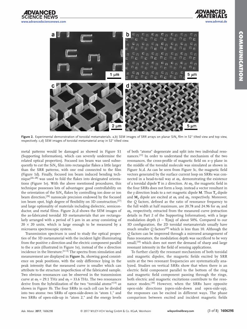
Transmission spectrum is used to study the optical proper-ties of the 3D metamaterial with the incident light illuminating from the positive z direction and the electric component parallel to the x axis (illustrated in Figure 1e), instead of the x direction incidence in the literature.[4,13] The spectra from simulation and measurement are displayed in Figure 3a, showing good consist-ence on peak positions, with the only difference lying in the peak intensity that the measured curve is smaller which can attribute to the structure imperfection of the fabricated sample. Two obvious resonances can be observed in the transmission curve at ω1 = 29.1 THz and ω2 = 33.6 THz. The two resonances derive from the hybridization of the two “toroidal atoms”[13] as shown in Figure 3b. The four SRRs in each cell can be divided into two atoms: two SRRs of open-side-down in “atom 1,” and two SRRs of open-side-up in “atom 2,” and the energy levels
of both “atoms” degenerate and split into two individual reso-nances.[13] In order to understand the mechanism of the two resonances, the cross-profile of magnetic field on x–y plane in the middle of the toroidal molecule was simulated as shown in Figure 3c,d. As can be seen from Figure 3c, the magnetic field vectors generated by the surface current loop on SRRs was con-nected in a head-to-tail way at ω1, demonstrating the existence of a toroidal dipole T in z direction. At ω2, the magnetic field in the four SRRs does not form a loop, instead a vector resultant in the y direction leads to a net magnetic dipole M. Thus Tz dipole and My dipole are excited at ω1 and ω2, respectively. Moreover, the Q factors, defined as the ratio of resonance frequency to the full width at half maximum, are 20.78 and 24.96 for ω1 and ω2, respectively, extracted from the measured curve (extraction details in Part 2 of the Supporting Information), with a large modulation depth (1 − T(ωi)) of about 50%. Compared to our 3D configuration, the 2D toroidal metamaterials usually have much smaller Q factors[29] which is less than 10. Although the Q factors can be improved through a mirrored arrangement of Fano resonators, the modulation depth was sacrificed to be very small,[10] which does not meet the demand of sharp and large resonant intensity in the field of sensing applications.
To further clarify the resonant mechanism of both toroidal and magnetic dipoles, the magnetic fields excited by SRR units at the two resonant frequencies are systematically ana-lyzed. Studies on vertical SRRs show that when there is an electric field component parallel to the bottom of the ring and magnetic field component passing through the rings, both electric and magnetic excitations contribute to the reso-nance modes.[30] However, when the SRRs have opposite open-side directions (open-side-down and open-side-up), the responses can be excited in different ways. The phase comparison between excited and incident magnetic fields
Adv. Mater. 2017, 1606298
www.advancedsciencenews.com www.advmat.de
Figure 2. Experimental demonstration of toroidal metamaterials. a,b) SEM images of SRR arrays on planar SiNx film in 52° tilted view and top view, respectively. c,d) SEM images of toroidal metamaterial array in 52° tilted view.
Co
mm
un
iCati
on
© 2017 WILEY-VCH Verlag GmbH & Co. KGaA, Weinheimwileyonlinelibrary.com1606298 (4 of 8)
of both kinds of SRRs (Figure S3, Supporting Information) gives a hint on these differences. For SRR of open-side-down, the excited magnetic field has an opposite direction compared to the incident magnetic field which is accordance with the Lenz’s law, while the excited surface current on the bottom side has the same direction with incident electric field, indicating a constructive superposition of the magnetic and electric excitation effects. But for SRR of open-side-up, the excited magnetic field has the same direction with the incident magnetic field, indicating a destructive superposi-tion of the magnetic and electric excitation effects. In short, the two kinds of “atoms” have opposite intrinsic resonance properties.
The combination of two SRRs with opposite split direc-tions has been used to cancel the electric dipole moment in magnetic and negative index metamaterials,[31] and here in this work it also contributes to the excitation of toroidal reso-nance mode. When there are two kinds of SRRs (“atom 1” and “atom 2”) in each molecule, the direction of excited mag-netic field should be opposite in the two “atoms.” As men-tioned previously, the intrinsic resonance of the SRR units split into two resonances, where the excited magnetic fields in the two atoms have the same and different directions at ω1 and ω2, respectively. The toroidal resonance at ω1 is rea-sonable, considering that the excited magnetic fields with
different directions in “atom 1” and “atom 2” form a loop in a head-to-tail manner, but the resonance at ω2 should be recon-sidered because the excited magnetic fields have the same direction. The intensity and phase of excited magnetic fields in the middle of SRRs are extracted (Figure S4, Supporting Information), which illustrates that at ω1 the SRR units were synchronously exited, while at ω2 they were out of sync because the light meet the bottom sides of different SRRs with a phase delay (detailed discussions in Part 4 of the Sup-porting Information). This means that when light illuminates from z direction, the excitation mechanisms of both toroidal and magnetic responses are different compared to x-direc-tion incidence.[4,13] In addition, simulation results show that a metamolecule composed of SRRs with the same open-side direction has only one magnetic response and no toroidal response (Figure S5, Supporting Information), proving the importance of opposite-split-direction configuration of the four SRRs.
From the above analysis, it can be concluded that it is the excited dipole modes (electric, magnetic, and toroidal) that contribute to the transmission spectra of this toroidal meta-material, thus the contributions of these dipoles can be quan-titatively analyzed by their radiation intensities. The radiation power magnitude of these multipoles can be described as follows[4,13]
Adv. Mater. 2017, 1606298
www.advancedsciencenews.comwww.advmat.de
Figure 3. Demonstration of the resonances in 3D metamaterial. a) Transmission spectra of the toroidal metamaterial by simulation and experiment. b) Illustration of toroidal atoms. c,d) Magnetic field distribution at ω1 and ω2, respectively.
Co
mm
un
iCatio
n
© 2017 WILEY-VCH Verlag GmbH & Co. KGaA, Weinheim wileyonlinelibrary.com (5 of 8) 1606298
PP MM
PP TT TT
23
| |23
| |
43
| |23
| |5
| |
40| |
1
4
32
4
32
5
4
6
52
6
52
6
52
5
∑
∑
ω ω
ω ω ω
ω
= +
+ ⋅ + +
+ +
αβ
αβ
Ic c
c c cQ
cM O
c
(1)
where P, M, T, Qαβ, and Mαβ are the electric dipole, magnetic dipole, toroidal dipole, electric quadrupole, and magnetic quad-rupole, respectively, c is the speed of light, ω is the angular fre-quency, and α, β = x, y, z. The magnitudes of these multipole moments can be calculated from surface current extracted from simulation (details in Part 6 of the Supporting Information).
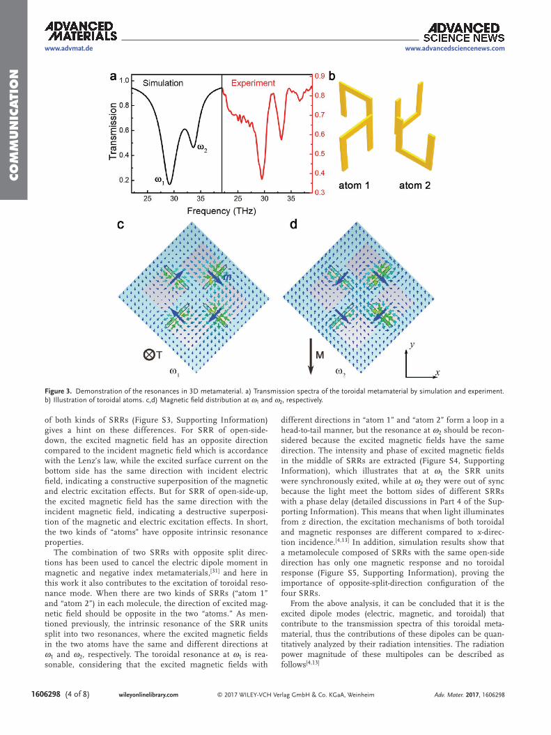
The radiation powers as a function of frequency are dis-played in Figure 4a. Unexpectedly, at ω1, the x component of the electric dipole Px has the largest intensity, which is an order larger than that of the toroidal dipole Tz. The large Px comes from the surface current I on the bottom of the SRRs, as shown in Figure 4b. The y components of the current labeled by black arrows on each SRR are cancelled, hence a net vector resultant
along x direction is produced causing large Px intensity. This strong Px is not desired and should be avoided as much as possible. At ω2, the strongest multipole moment is not mag-netic dipole My but electric quadrupole, of which the current direction on the bottom of SRR can be seen in Figure 3c, and the intensity of My is about one order smaller than the electric quadrupole. This means that in this “toroidal metamaterial,” the toroidal moment is not the prominent component due to the strong electric multipoles when the incident light comes from the positive z direction.
So long as the intensity of these multipole components has been fixed, the origin of the transmission minima in Figure 3a can be discussed based on their radiation properties. In gen-eral, the transmission of optical signal should be described as Etransmitted = Eincident + Escattered. Here Escattered represents the radiation of the induced multipoles including electric dipole Px, magnetic dipole My, toroidal dipole Tz, and quadrupoles on the SRRs along the direction of wave vector k. Therefore, all the multipoles have contributions to the transmission minimum in the form of out-of-phase cancellation to the incident wave.
Adv. Mater. 2017, 1606298
www.advancedsciencenews.com www.advmat.de
Figure 4. Demonstration of the excited multipoles. a) Dispersion of radiation power for various multipole moments induced in the toroidal metamate-rial. b,c) Surface current distribution and electric dipole orientation on SRR units at ω1 and ω2.

Co
mm
un
iCati
on
© 2017 WILEY-VCH Verlag GmbH & Co. KGaA, Weinheimwileyonlinelibrary.com1606298 (6 of 8) Adv. Mater. 2017, 1606298
www.advancedsciencenews.comwww.advmat.de
Although the Tz dipole does not have the largest intensity among all these multipoles, this does not mean that Tz has the weakest radiation power in the far-field. The energy radiation flux in different directions is not solely related to dipole inten-sity but also concerned with the radiation angle.[32,33] The far-field radiation pattern of electric dipole can be expressed as[2]
pp rr pp4
| | 14
32 2ω
π ( )( )= − ⋅Sc
(2)
where ⟨S⟩ is time-averaged Poynting vector, r and p are unit vec-tors, thus we get
sin2 θ∝S (3)
Here θ is the angle between r and p vectors. This relation-ship is suitable not only for electric dipole, but also for mag-netic and toroidal dipoles.[2,32]
Since the incident light comes from z direction, Tz has no contribution to the far-field radiation power in the forward z direction, while Px and My have the largest angular radiation component. This reminds us that if the wave vector k has an angle with respect to z direction, the radiation intensity of Tz in the direction of k in the far-field will increase while the Px will decrease due to the coefficient of sin2θ in Equation (3). Figure 5a displays the oblique incidence of p-polarized light,
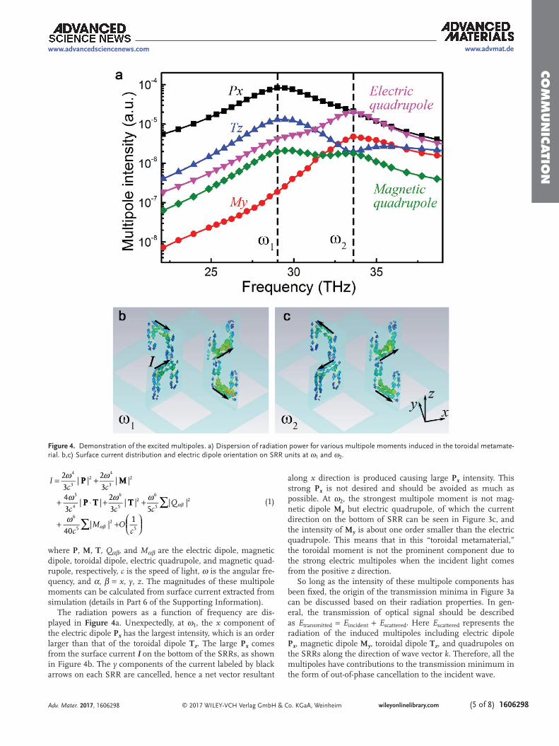
that the magnetic field is always parallel to the x–y plane. In the far-field of k direction, the radiation flux of Px, My, and Tz has a coefficient of sin2(π/2 − θ), sin2θ /2, and sin2θ, respectively. Figure 5b shows the normalized energy flux density in k direc-tion at ω1 when the light incident angle changes from 0° to 75°. The Px flux has the largest intensity when θ is 0°, which is also illustrated in Figure 4a. However, when the incident angle increases from 0° to 75°, the Tz flux increases and the Px flux decreases due to different coefficients with respect to angle θ. When the angle reaches 75°, the Tz flux exceeds Px flux, and Tz has the largest contribution to the macroscopic transmission spectrum. Thus, just by a feasible scheme of adjusting the inci-dent angle, the contribution from the toroidal moments Tz to the radiation intensity will play a dominate role in the trans-mission properties of the toroidal metamaterials. It should be noted that in Figure 5b Pz flux is also given, because it has a coefficient of sin2θ, which increases with incident angle. How-ever, its intensity is always smaller than Tz, indicating that Pz is not the dominant multipole of the macroscopic transmission property.
In order to prove the growing contribution of Tz to the far-field, further experiments were carried out and the transmis-sion data by oblique incident excitation are shown in Figure 5, which fit very well with the simulated results. From the simu-lated results in Figure 5c, when the incident angle increases from 0° to 75° with a step of 5°, the modulation depth of
Figure 5. Far-field radiation property of toroidal metamaterial. a) Schematic of oblique excitation of toroidal resonance. b) Energy flux intensity of dif-ferent multipole at ω1 and ω2. c) Transmission spectra at different incident angles from 0° to 75° by simulation. d) Transmission spectra at different incident angles from 0° to 75° by experiment.
Co
mm
un
iCatio
n
© 2017 WILEY-VCH Verlag GmbH & Co. KGaA, Weinheim wileyonlinelibrary.com (7 of 8) 1606298Adv. Mater. 2017, 1606298
www.advancedsciencenews.com www.advmat.de
toroidal resonance ω1 increases from 80% to 97% and move slightly to low frequency (white dashed line), while the Q factor increases by over 70%. The growing Q factor again proves the larger contribution of Tz at ω1 compared to Px. At ω2, the reso-nance also shows a red shift as the incident angle increases. The peak shift comes from the phase changes when the inci-dent light reaches “atom 1” and “atom 2” in an oblique way. From the experimental data in Figure 5d, the peak shift of ω1 is a little larger than the simulated one due to the imperfect sample fabrication and measurement setup. Meanwhile, when the incident angle is very large (over 65°), the modulation depth of ω1 drops down rapidly. This is because of the reducing pro-jected area of the toroidal metamaterial pattern in the micro-scope system with a coefficient of cosθ, and a large proportion of the incident light passes through the SiNx film instead of interacting with the structures. The magnetic field and sur-face current distribution at ω1 with an incident angle of 75° is shown in Figure S6 (Supporting Information), which confirms the existence of toroidal moment.
In conclusion, a fabrication technique for 3D metal–dielec-tric composite structures in micro-/nanoscale was developed in which dielectric film is used as a framework for ease of the fabrication of metal patterns with arbitrary spatial orienta-tion through focused ion beam induced bending techniques, showing the advantage of good controllability, nanoscale preci-sion, high degree of flexibility on 3D construction, etc., without the weakness of short circuit by conductive substrate. Based on this technique, toroidal metamaterial composed of four SRRs was fabricated, and toroidal moments excited by vertical inci-dent light were observed with high-Q factor in mid-infrared region. The intensity of toroidal dipole in far-field region becomes dominant when the incident angle increases. This technique offers a scalable method for excitation of toroidal moments, which can also be used in other field including 3D optical antennas, light modulators and logic elements, etc.
Experimental SectionFabrication Process: 5 nm Cr film was first deposited on 100 nm thick
SiNx window (Shanghai NTI Co., Ltd.) as a conductive layer by thermal evaporation, after which polymethyl methacrylate (PMMA) resist (495 A5) was spin-coated on the window and baked at 180 °C for 1 min. Then, the resist layer was patterned with SRR shapes by electron beam lithography (Raith 150). Metal deposition and acetone lift-off process transfers the resist pattern to gold. Focused ion beam (Helios 600i, FEI) was used to cut through the SiNx film into flakes and then folded them up by scanning the bottom of the flakes from the back side of the SiNx window. Finally, the Cr conductive layer was removed by wet etching in Ce(NH4)4(NO6)6/CH3COOH solution. It took 2.2 h for the focused ion beam folding fabrication of this 100 × 100 µm pattern using an ion beam current of 0.23 nA. A 3D pattern array with larger area can be fabricated as long as more time is spent, and the time increases proportional to its area. A larger ion beam is also an option to reduce the fabrication time, but it will reduce the fabrication accuracy which leads to bad edges of the SiNx flakes.
Optical Measurement: Transmission spectra were measured using a ×15, NA (numerical aperture) = 0.4 objective lens in an optical microscope (Hyperion 2000) coupled to a Fourier-transform infrared spectrometer (Vertex 80, Bruker) through a 40 µm × 40 µm spatial aperture. A homemade aperture was inserted between the sample and objective to confine the illumination cone with a conical angle of 5°,
and the samples were tilted correspondingly to obtain normal incidence during measurement.[34] The transmission spectra were calibrated using air (holes of the grid) as a reference.
Numerical Simulation: The transmission spectra were simulated by the finite-difference time-domain method, and the dispersion relation of gold in the simulation was described by Drude model.[35] The current distributions were simulated using the commercial software package CST Microwave Studio. Realistic parameters were used for describing gold’s lossy properties, with an electric conductivity of 4.561 × 10⁷ S m−1. The surface current distributions were obtained using an H-field/surface current monitor.
Supporting InformationSupporting Information is available from the Wiley Online Library or from the author.
AcknowledgementsZ.L., S.D., and A.C. contributed equally to this work. This work was supported by the Ministry of Science and Technology of China (2016YFA0200803, 2016YFA0200400, 2016YFA0301102), the National Natural Science Foundation of China (Grant Nos. 91323304, 11504414, 11674387, 11574368, 61505164, 11574369, 11574385), and the Strategic Priority Research Program of the Chinese Academy of Sciences (Grant No. XDB07020200).
Received: November 21, 2016Revised: January 10, 2017
Published online:
[1] I. B. Zel’dovich, Sov. Phys. JETP 1958, 6, 1148.[2] N. Papasimakis, V. A. Fedotov, V. Savinov, T. A. Raybould,
N. I. Zheludev, Nat. Mater. 2016, 15, 263.[3] a) W. C. Haxton, Science 1997, 275, 1753; b) V. M. Dubovik,
V. V. Tugushev, Phys. Rep. 1990, 187, 145; c) V. V. Flambaum, D. W. Murray, Phys. Rev. C 1997, 56, 1641; d) A. Ceulemans, L. F. Chibotaru, P. W. Fowler, Phys. Rev. Lett. 1998, 80, 1861.
[4] T. Kaelberer, V. A. Fedotov, N. Papasimakis, D. P. Tsai, N. I. Zheludev, Science 2010, 330, 1510.
[5] N. Papasimakis, V. A. Fedotov, K. Marinov, N. I. Zheludev, Phys. Rev. Lett. 2009, 103, 093901.
[6] Q. W. Ye, L. Y. Guo, M. H. Li, Y. Liu, B. X. Xiao, H. L. Yang, Phys. Scr. 2013, 88, 055002.
[7] K. Marinov, A. D. Boardman, V. A. Fedotov, N. Zheludev, New J. Phys. 2007, 9, 324.
[8] Y.-W. Huang, W. T. Chen, P. C. Wu, V. A. Fedotov, N. I. Zheludev, D. P. Tsai, Sci. Rep. 2013, 3, 1237.
[9] X.-L. Zhang, S. B. Wang, Z. Lin, H.-B. Sun, C. T. Chan, Phys. Rev. A 2015, 92, 043804.
[10] M. Gupta, V. Savinov, N. Xu, L. Cong, G. Dayal, S. Wang, W. Zhang, N. I. Zheludev, R. Singh, Adv. Mater. 2016, 28, 8206.
[11] Y. Fan, Z. Wei, H. Li, H. Chen, C. M. Soukoulis, Phys. Rev. B 2013, 87, 115417.
[12] V. A. Fedotov, A. V. Rogacheva, V. Savinov, D. P. Tsai, N. I. Zheludev, Sci. Rep. 2013, 3, 2967.
[13] Y.-W. Huang, W. T. Chen, P. C. Wu, V. Fedotov, V. Savinov, Y. Z. Ho, Y.-F. Chau, N. I. Zheludev, D. P. Tsai, Opt. Express 2012, 20, 1760.
[14] a) Z.-G. Dong, P. Ni, J. Zhu, X. Yin, X. Zhang, Opt. Express 2012, 20, 13065; b) L. Guo, M. Li, H. Yang, X. Huang, S. Wu, J. Phys. D: Appl. Phys. 2014, 47, 415501.

Co
mm
un
iCati
on
© 2017 WILEY-VCH Verlag GmbH & Co. KGaA, Weinheimwileyonlinelibrary.com1606298 (8 of 8) Adv. Mater. 2017, 1606298
www.advancedsciencenews.comwww.advmat.de
[15] a) N. Katsarakis, T. Koschny, M. Kafesaki, E. N. Economou, C. M. Soukoulis, Appl. Phys. Lett. 2004, 84, 2943; b) M. Li, L. Guo, J. Dong, H. Yang, Appl. Phys. Express 2014, 7, 082201; c) T. A. Raybould, V. A. Fedotov, N. Papasimakis, I. Kuprov, I. J. Youngs, W. T. Chen, D. P. Tsai, N. I. Zheludev, Phys. Rev. B 2016, 94, 035119.
[16] Z.-G. Dong, J. Zhu, J. Rho, J.-Q. Li, C. Lu, X. Yin, X. Zhang, Appl. Phys. Lett. 2012, 101, 144105.
[17] a) B. Ögüt, N. Talebi, R. Vogelgesang, W. Sigle, P. A. van Aken, Nano Lett. 2012, 12, 5239; b) N. Talebi, B. Ögüt, W. Sigle, R. Vogelgesang, P. A. van Aken, Appl. Phys. A: Mater. Sci. Process. 2014, 116, 947.
[18] J. Li, Y. Zhang, R. Jin, Q. Wang, Q. Chen, Z. Dong, Opt. Lett. 2014, 39, 6683.
[19] a) A. E. Miroshnichenko, A. B. Evlyukhin, Y. F. Yu, R. M. Bakker, A. Chipouline, A. I. Kuznetsov, B. Luk’yanchuk, B. N. Chichkov, Y. S. Kivshar, Nat. Commun. 2015, 6, 8069; b) W. Liu, J. Shi, B. Lei, H. Hu, A. E. Miroshnichenko, Opt. Express 2015, 23, 24738; c) W. Liu, J. Zhang, A. E. Miroshnichenko, Laser Photonics Rev. 2015, 9, 564.
[20] a) A. A. Basharin, M. Kafesaki, E. N. Economou, C. M. Soukoulis, V. A. Fedotov, V. Savinov, N. I. Zheludev, Phys. Rev. X 2015, 5, 011036; b) J. Li, J. Shao, Y.-H. Wang, M.-J. Zhu, J.-Q. Li, Z.-G. Dong, Opt. Express 2015, 23, 29138; c) W. Liu, J. Zhang, B. Lei, H. Hu, A. E. Miroshnichenko, Opt. Lett. 2015, 40, 2293.
[21] W. T. Chen, C. J. Chen, P. C. Wu, S. Sun, L. Zhou, G.-Y. Guo, C. T. Hsiao, K.-Y. Yang, N. I. Zheludev, D. P. Tsai, Opt. Express 2011, 19, 12837.
[22] K. Fan, A. C. Strikwerda, H. Tao, X. Zhang, R. D. Averitt, Opt. Express 2011, 19, 12619.
[23] C.-C. Chen, A. Ishikawa, Y.-H. Tang, M.-H. Shiao, D. P. Tsai, T. Tanaka, Adv. Opt. Mater. 2015, 3, 44.
[24] a) D. B. Burckel, J. R. Wendt, G. A. Ten Eyck, A. R. Ellis, I. Brener, M. B. Sinclair, Adv. Mater. 2010, 22, 3171; b) D. B. Burckel, J. R. Wendt, G. A. Ten Eyck, J. C. Ginn, A. R. Ellis, I. Brener, M. B. Sinclair, Adv. Mater. 2010, 22, 5053.
[25] a) X. Xiong, S.-C. Jiang, Y.-H. Hu, R.-W. Peng, M. Wang, Adv. Mater. 2013, 25, 3994; b) X. Xiong, Z.-H. Xue, C. Meng, S.-C. Jiang, Y.-H. Hu, R.-W. Peng, M. Wang, Phys. Rev. B 2013, 88, 115105.
[26] A. Cui, Z. Liu, J. Li, T. H. Shen, X. Xia, Z. Li, Z. Gong, H. Li, B. Wang, J. Li, H. Yang, W. Li, C. Gu, Light: Sci. Appl. 2015, 4, e308.
[27] Z. Liu, A. Cui, Z. Gong, H. Li, X. Xia, T. H. Shen, J. Li, H. Yang, W. Li, C. Gu, Sci. Rep. 2016, 6, 28764.
[28] Z. Liu, Z. Liu, J. Li, W. Li, J. Li, C. Gu, Z.-Y. Li, Sci. Rep. 2016, 6, 27817.
[29] a) M. Gupta, R. Singh, Adv. Opt. Mater. 2016, 4, 2119; b) Y. Bao, X. Zhu, Z. Fang, Sci. Rep. 2015, 5, 11793.
[30] P. Gay-Balmaz, O. J. F. Martin, J. Appl. Phys. 2002, 92, 2929.[31] a) J. B. Pendry, A. J. Holden, D. J. Robbins, W. J. Stewart, IEEE Trans.
Microwave Theory Tech. 1999, 47, 2075; b) D. R. Smith, W. J. Padilla, D. C. Vier, S. C. Nemat-Nasser, S. Schultz, Phys. Rev. Lett. 2000, 84, 4184; c) R. A. Shelby, D. R. Smith, S. Schultz, Science 2001, 292, 77.
[32] V. Savinov, V. A. Fedotov, N. I. Zheludev, Phys. Rev. B 2014, 89, 205112.
[33] E. E. Radescu, G. Vaman, Phys. Rev. E 2002, 65, 046609.[34] J. Li, B. Jia, G. Zhou, M. Gu, Opt. Express 2006, 14, 10740.[35] A. B. D. A. D. Rakic, J. M. Elazar, M. L. Majewski, Appl. Opt. 1998,
37, 5271.