HIGH VOLTAGE. INSTRUMENT · PDF file› Silicone rubber insulator. › Capacitive...
60
HIGH VOLTAGE. INSTRUMENT TRANSFORMERS.
Transcript of HIGH VOLTAGE. INSTRUMENT · PDF file› Silicone rubber insulator. › Capacitive...

HIGH VOLTAGE.INSTRUMENT TRANSFORMERS.

This document may be subject to changes. Contact ARTECHE to confi rm the characteristics and availability of the products described here.
Moving together
Instrument transformers | High voltage
CONTENTS
1. Current transformers | 4 › Oil-paper insulation › Gas insulation › Dry insulation
2. Inductive voltage transformers | 18 › Oil-paper insulation › Gas insulation
3. Combined transformers | 26 › Oil-paper insulation
4. Capacitive voltage transformers and coupling capacitors | 34 › Oil-paper insulation
5. Power voltage transformers | 42 › Oil-paper insulation › Gas insulation
6. Other technologies | 50 › Medium voltage outdoor instrument transformers | 52 › Voltage transformers for GIS | 53 › Optical current transformers. Digital measurement | 54 › Line traps | 55
7. Quality & environment | 56
8. Service | 58
4 Instrument transformers | High voltage
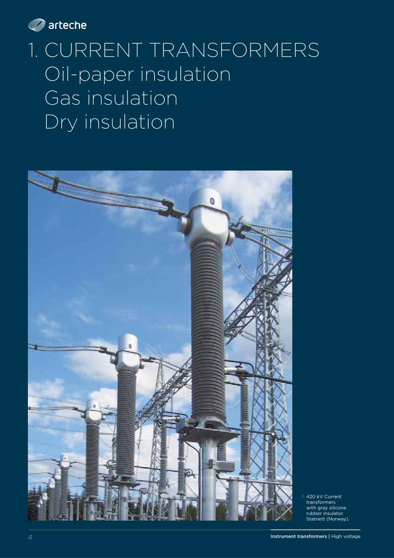
1. CURRENT TRANSFORMERSOil-paper insulationGas insulationDry insulation
› 420 kV Current transformers with gray silicone rubber insulator. Statnett (Norway).
5Instrument transformers | High voltage
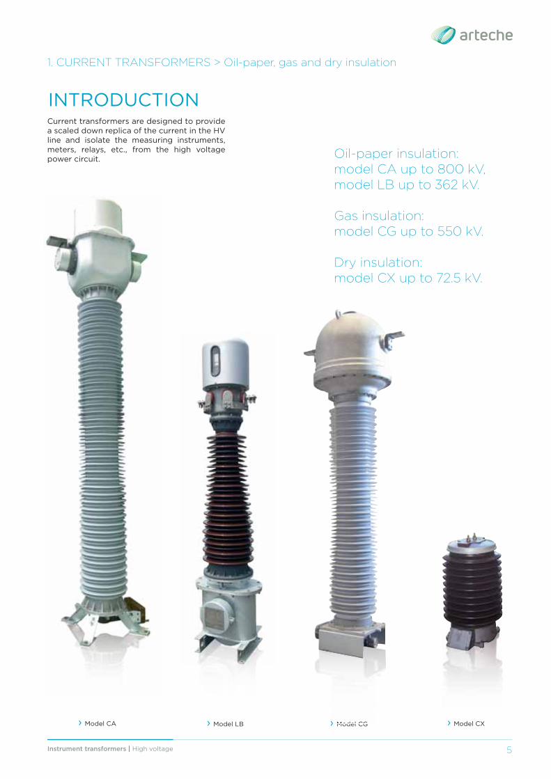
Current transformers are designed to provide a scaled down replica of the current in the HV line and isolate the measuring instruments, meters, relays, etc., from the high voltage power circuit.
INTRODUCTION
Oil-paper insulation: model CA up to 800 kV, model LB up to 362 kV.
Gas insulation:model CG up to 550 kV.
Dry insulation:model CX up to 72.5 kV.
1. CURRENT TRANSFORMERS > Oil-paper, gas and dry insulation
› Model LB › Model CG › Model CA › Model CX› Model CG
Instrument transformers | High voltage6
1. CURRENT TRANSFORMERS > Oil-paper, gas and dry insulation
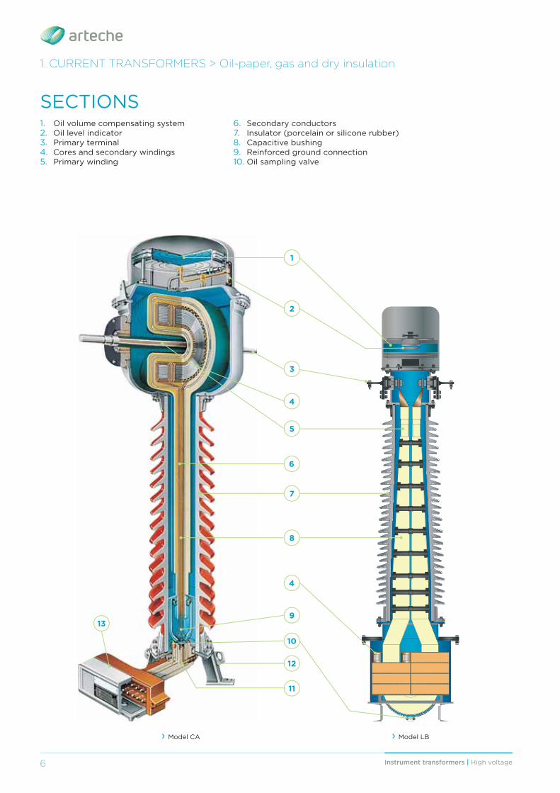
1. Oil volume compensating system2. Oil level indicator3. Primary terminal4. Cores and secondary windings5. Primary winding
6. Secondary conductors7. Insulator (porcelain or silicone rubber)8. Capacitive bushing9. Reinforced ground connection10. Oil sampling valve
SECTIONS
1
2
3
4
6
7
8
139
10
12
11
› Model CA › Model LB
4
5
7Instrument transformers | High voltage
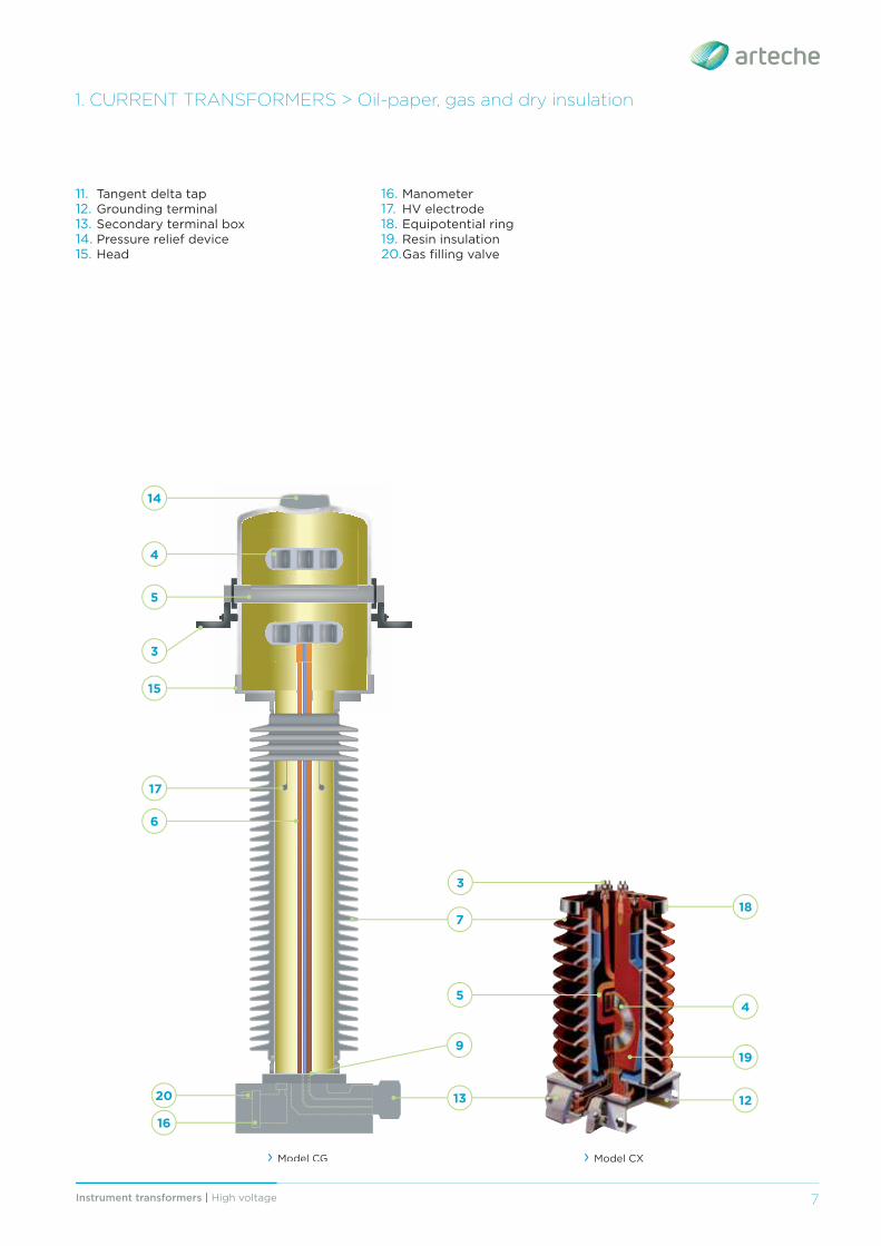
› Model CG › Model CX
11. Tangent delta tap 12. Grounding terminal13. Secondary terminal box14. Pressure relief device15. Head
16. Manometer17. HV electrode18. Equipotential ring19. Resin insulation20. Gas fi lling valve
1. CURRENT TRANSFORMERS > Oil-paper, gas and dry insulation
5
4
6
7
13
14
15
16
3
17
9
3
18
19
45
1220
Instrument transformers | High voltage8
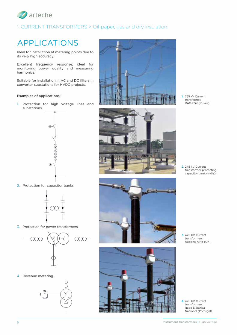
APPLICATIONSIdeal for installation at metering points due to its very high accuracy.
Excellent frequency response; ideal for monitoring power quality and measuring harmonics.
Suitable for installation in AC and DC fi lters in converter substations for HVDC projects.
Examples of applications:
1. Protection for high voltage lines and substations.
2. Protection for capacitor banks.
3. Protection for power transformers.
4. Revenue metering.
M
M
M
1. 765 kV Current transformer. RAO-FSK (Russia).
2. 245 kV Current transformer protecting capacitor bank (India).
3. 420 kV Current transformers. National Grid (UK).
4. 420 kV Current transformers. Rede Eléctrica Nacional (Portugal).
1. CURRENT TRANSFORMERS > Oil-paper, gas and dry insulation
9Instrument transformers | High voltage
1. CURRENT TRANSFORMERS > Oil-paper, gas and dry insulation
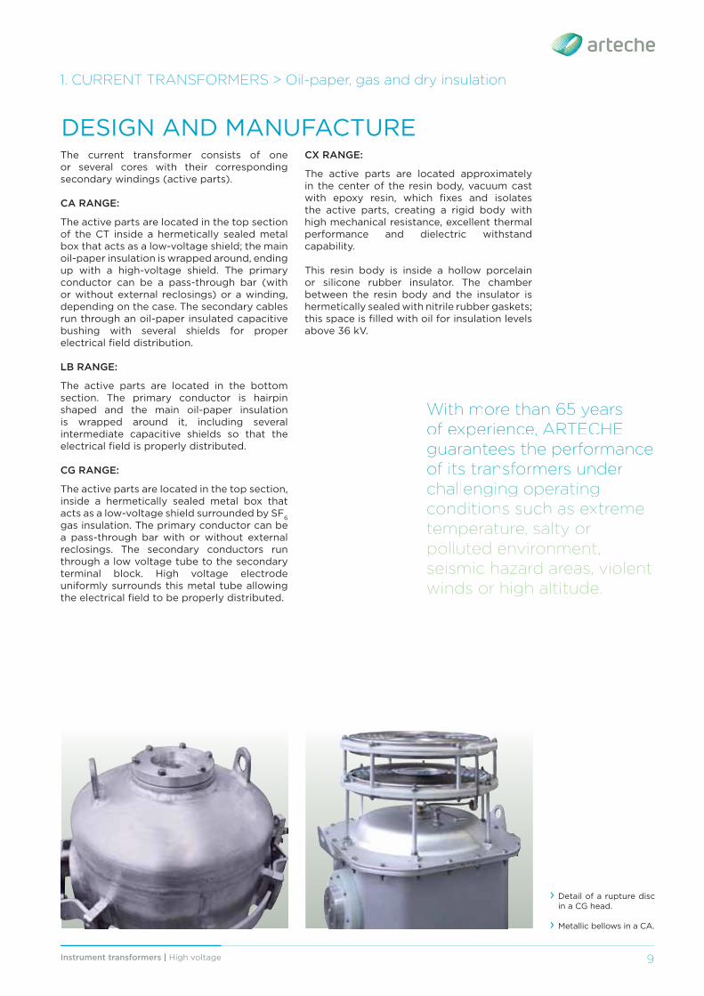
› Detail of a rupture disc in a CG head.
› Metallic bellows in a CA.
WWiitthh mmoorree tthhaann 6655 yyeeaarrss oofff eexxppeerriiieennccee, AAARRRTTTEEECCCHHHEEE gguuaarraanntteeeess tthhee ppeerrffoorrmmaannccee ooff iittss ttrraannssffoorrmmeerrss uunnddeerr cchhhalllllleennggggiiinngggg ooppppeeratttiiinngggg ccoonndddiiitttiiioonnss ssuucchhh aass eexxtttrreemmee ttteemmpppeerraatttuurree,, ssaallltttyyy oorr polluted environment, seismic hazard areas, violent winds or high altitude.
The current transformer consists of one or several cores with their corresponding secondary windings (active parts).
CA RANGE:
The active parts are located in the top section of the CT inside a hermetically sealed metal box that acts as a low-voltage shield; the main oil-paper insulation is wrapped around, ending up with a high-voltage shield. The primary conductor can be a pass-through bar (with or without external reclosings) or a winding, depending on the case. The secondary cables run through an oil-paper insulated capacitive bushing with several shields for proper electrical fi eld distribution.
LB RANGE:
The active parts are located in the bottom section. The primary conductor is hairpin shaped and the main oil-paper insulation is wrapped around it, including several intermediate capacitive shields so that the electrical fi eld is properly distributed.
CG RANGE:
The active parts are located in the top section, inside a hermetically sealed metal box that acts as a low-voltage shield surrounded by SF6 gas insulation. The primary conductor can be a pass-through bar with or without external reclosings. The secondary conductors run through a low voltage tube to the secondary terminal block. High voltage electrode uniformly surrounds this metal tube allowing the electrical fi eld to be properly distributed.
DESIGN AND MANUFACTURECX RANGE:
The active parts are located approximately in the center of the resin body, vacuum cast with epoxy resin, which fi xes and isolates the active parts, creating a rigid body with high mechanical resistance, excellent thermal performance and dielectric withstand capability.
This resin body is inside a hollow porcelain or silicone rubber insulator. The chamber between the resin body and the insulator is hermetically sealed with nitrile rubber gaskets; this space is fi lled with oil for insulation levels above 36 kV.
Instrument transformers | High voltage10
ADVANTAGES › Variety of designs and technologies of insulation for greater adaptation to client needs.
› Robust mechanical strength and reduced size due to a compact design that is easy to transport, store and install, and which reduces visual impact.
› Hermetically sealed to guarantee complete water tightness with the minimum volume of oil or gas (Each unit is tested individually).
› Excellent response under extreme weather conditions (Oil-paper insulation from -55°C; up to +55°C; gas insulation from -45°C up to +55°C), altitudes over 1,000 m.a.s.l., seis-mic hazard areas, violent winds, etc.
› Maintenance-free throughout their lifespan. › Very high and invariable accuracy (up to 0.1%).
› Protection for the secondary windings in the terminal block.
› Wide range of primary and secondary terminals.
› Diff erent cable glands and accessories available.
› Each transformer is routine tested for partial discharges, tangent delta (DDF), insulation and accuracy and designed to withstand all the type tests included in the standards.
› Compliance to any international standards: IEC, IEEE, UNE, BS, VDE, SS, CAN/CSA, AS, NBR, JIS, GOST, NF…
› Offi cially homologated in-house testing facilities.
› May be transported and stored horizontally or vertically.
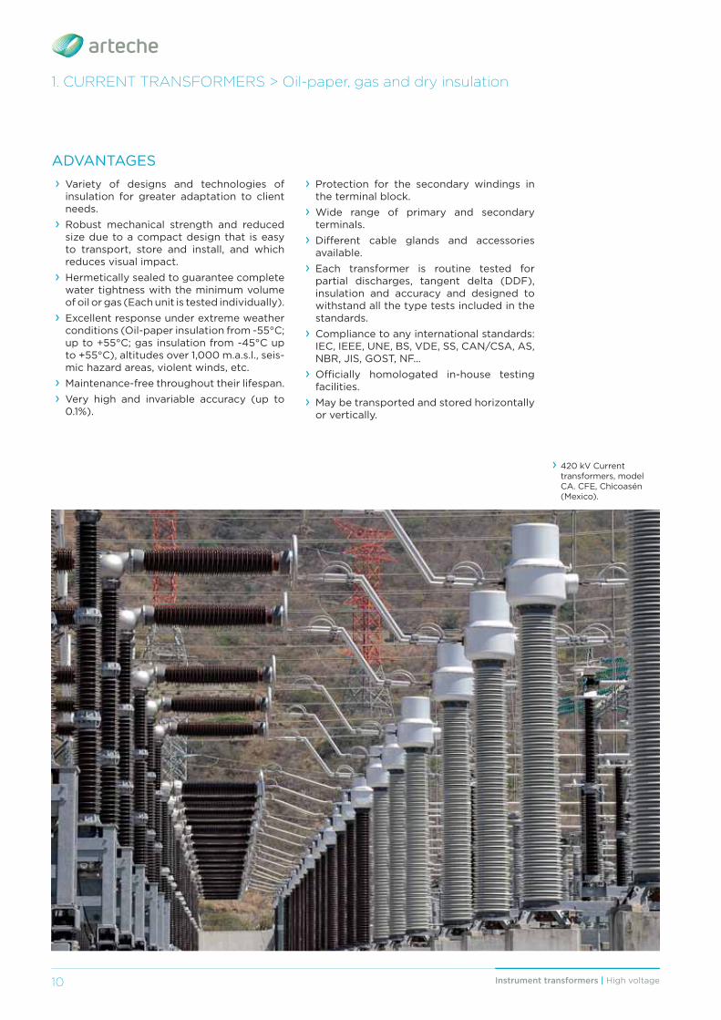
› 420 kV Current transformers, model CA. CFE, Chicoasén (Mexico).
1. CURRENT TRANSFORMERS > Oil-paper, gas and dry insulation
11Instrument transformers | High voltage 11
1. CURRENT TRANSFORMERS > Oil-paper, gas and dry insulation
OIL-PAPER INSULATION:
Wide range of primary currents: from 1 to 5,000 A.
Oil level compensating system that eff ectively regulates changes in oil volume mainly caused by temperature.
Oil sampling valve for periodic analysis.
The materials used for construction are recyclable and resistant to the elements. Its advanced design adheres to environmental regulations through the use of high quality insulating oils, free of PCB.
Top-core Type:
› All types of measurement and protection cores: multi-ratio, linear…
› Very high rated currents and short-circuit currents.
› Reinforced safety design, resistant to inter-nal arc.
› Metallic oil bellows and tangent delta mea-surement tap.
Hairpin Type:
› Excellent seismic performance. › Good heat dissipation in the primary conductor.
› Reduced size makes it extremely easy to handle.
› Metallic oil bellows and tangent delta mea-surement tap.
OPTIONS:
› Silicone rubber insulator. › Capacitive voltage tap.
GAS INSULATION:
› Total safety in case of internal arc: overpressure is relieved by the pressure relief device (rupture disc) in the top part of the head.
› The silicone rubber insulator guarantees safety during transportation and service.
› Online monitoring of the insulation status with a manometer alarm.
› Compact and very light design. › Designed to minimize gas volume, pressure and leaks, thus reducing its environmental impact.
DRY INSULATION:
› Cast in high dielectric strength resin. › Primary winding with spark gap for over-voltage protection.
› Compact design for easy handling. › May be transported, stored and installed vertically or horizontally.
› Porcelain or silicone rubber insulators.
IInnnnoovvaattiioonnss iinn ttrraannssffoorrmmeerrss iiinn rreecceennttt yyeeaarrss hhhaavvee mmaadddee tthheemm mmoorree eeffiffi cciieenntt wwiitthh ccoommpppaacctt ddeessiigggnnss,, mmaakkiinnggg ttthhheemm eeaassyyyy tttoo tttrraannsspppppoorrttt,, sstttoorree aannddd iiinnsstttaallllll;;; mmiiinniiimmiiizziiinnggg vviiissuuaalll iiimmpppaaccttt.
12 Instrument transformers | High voltage
ARTECHE transformers are installed in over 150 countries.
13Instrument transformers | High voltage
1. CURRENT TRANSFORMERS > Oil-paper, gas and dry insulation
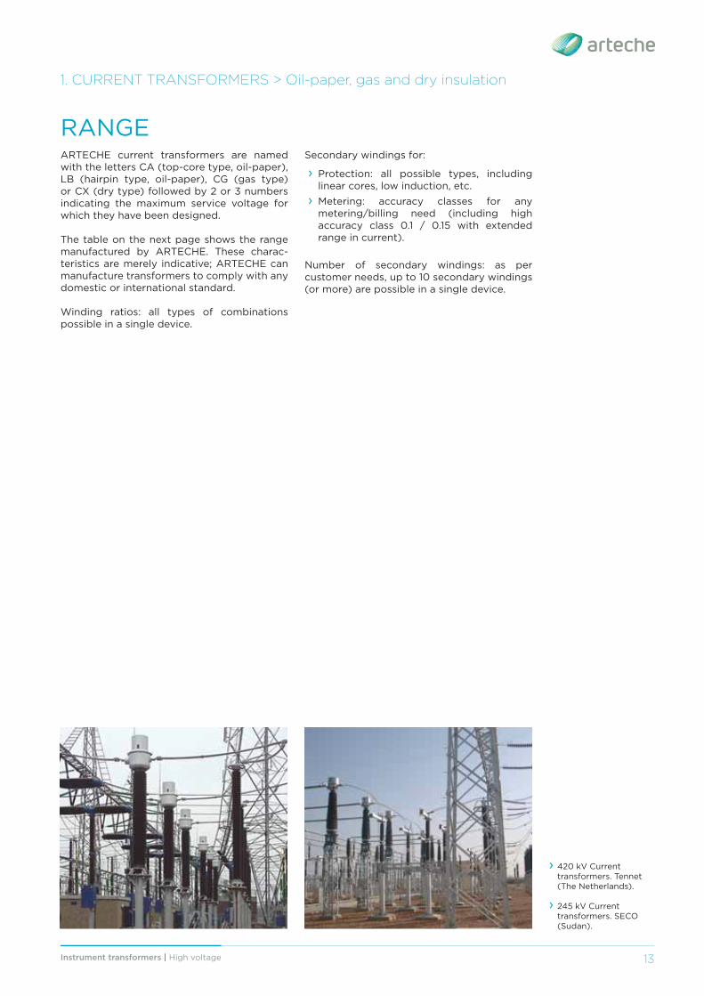
RANGEARTECHE current transformers are named with the letters CA (top-core type, oil-paper), LB (hairpin type, oil-paper), CG (gas type) or CX (dry type) followed by 2 or 3 numbers indicating the maximum service voltage for which they have been designed.
The table on the next page shows the range manufactured by ARTECHE. These charac-teristics are merely indicative; ARTECHE can manufacture transformers to comply with any domestic or international standard.
Winding ratios: all types of combinations possible in a single device.
› 420 kV Current transformers. Tennet (The Netherlands).
› 245 kV Current transformers. SECO (Sudan).
Secondary windings for:
› Protection: all possible types, including linear cores, low induction, etc.
› Metering: accuracy classes for any metering/billing need (including high accuracy class 0.1 / 0.15 with extended range in current).
Number of secondary windings: as per customer needs, up to 10 secondary windings (or more) are possible in a single device.
Instrument transformers | High voltage14
1. CURRENT TRANSFORMERS > Oil-paper, gas and dry insulation
$$06
$$02
H
T
A
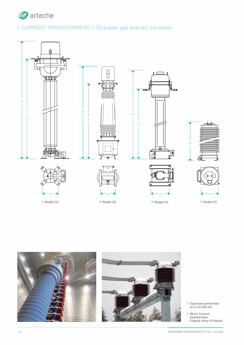
› Model CA › Model CG
A
H
T
› Model CX
A
H
› Type test performed on a CG 245 kV.
› 36 kV Current transformers. Fingrid, Kimy (Finland).
› Model LB
A
H
T
15Instrument transformers | High voltage 15
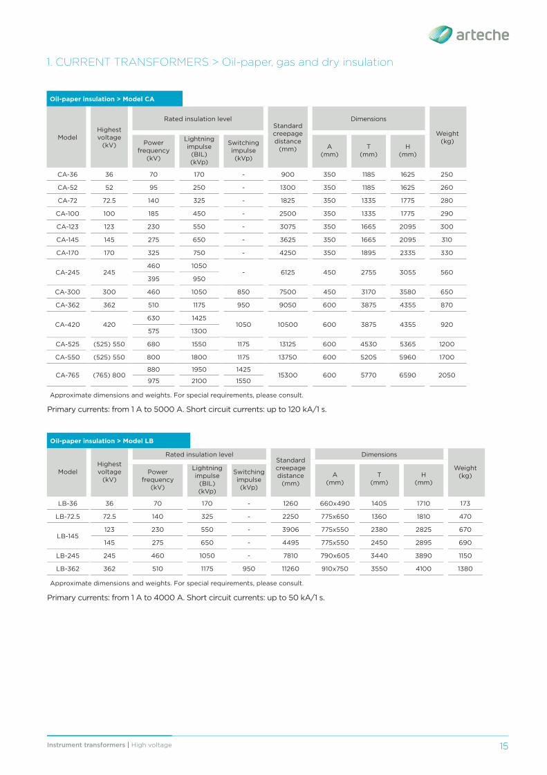
Primary currents: from 1 A to 5000 A. Short circuit currents: up to 120 kA/1 s.
Oil-paper insulation > Model CA
ModelHighest voltage
(kV)
Rated insulation levelStandard creepage distance
(mm)
Dimensions
Weight(kg)Power
frequency (kV)
Lightning impulse
(BIL)(kVp)
Switching impulse (kVp)
A(mm)
T(mm)
H(mm)
CA-36 36 70 170 - 900 350 1185 1625 250
CA-52 52 95 250 - 1300 350 1185 1625 260
CA-72 72.5 140 325 - 1825 350 1335 1775 280
CA-100 100 185 450 - 2500 350 1335 1775 290
CA-123 123 230 550 - 3075 350 1665 2095 300
CA-145 145 275 650 - 3625 350 1665 2095 310
CA-170 170 325 750 - 4250 350 1895 2335 330
CA-245 245460 1050
- 6125 450 2755 3055 560395 950
CA-300 300 460 1050 850 7500 450 3170 3580 650
CA-362 362 510 1175 950 9050 600 3875 4355 870
CA-420 420630 1425
1050 10500 600 3875 4355 920575 1300
CA-525 (525) 550 680 1550 1175 13125 600 4530 5365 1200
CA-550 (525) 550 800 1800 1175 13750 600 5205 5960 1700
CA-765 (765) 800880 1950 1425
15300 600 5770 6590 2050 975 2100 1550
Approximate dimensions and weights. For special requirements, please consult.
Primary currents: from 1 A to 4000 A. Short circuit currents: up to 50 kA/1 s.
1. CURRENT TRANSFORMERS > Oil-paper, gas and dry insulation
Oil-paper insulation > Model LB
ModelHighest voltage
(kV)
Rated insulation levelStandard creepage distance
(mm)
Dimensions
Weight(kg)A
(mm)T
(mm)H
(mm)
Power frequency
(kV)
Lightning impulse
(BIL)(kVp)
Switching impulse (kVp)
LB-36 36 70 170 - 1260 660x490 1405 1710 173
LB-72.5 72.5 140 325 - 2250 775x650 1360 1810 470
LB-145123 230 550 - 3906 775x550 2380 2825 670
145 275 650 - 4495 775x550 2450 2895 690
LB-245 245 460 1050 - 7810 790x605 3440 3890 1150
LB-362 362 510 1175 950 11260 910x750 3550 4100 1380
Approximate dimensions and weights. For special requirements, please consult.
Instrument transformers | High voltage16
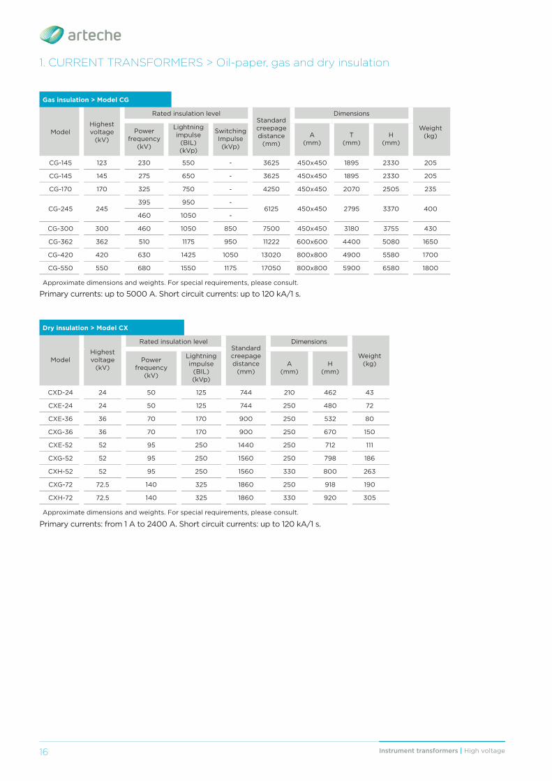
Gas insulation > Model CG
ModelHighest voltage
(kV)
Rated insulation levelStandard creepage distance
(mm)
Dimensions
Weight(kg)
Power frequency
(kV)
Lightning impulse
(BIL)(kVp)
Switching Impulse (kVp)
A(mm)
T(mm)
H(mm)
CG-145 123 230 550 - 3625 450x450 1895 2330 205
CG-145 145 275 650 - 3625 450x450 1895 2330 205
CG-170 170 325 750 - 4250 450x450 2070 2505 235
CG-245 245395 950 -
6125 450x450 2795 3370 400460 1050 -
CG-300 300 460 1050 850 7500 450x450 3180 3755 430
CG-362 362 510 1175 950 11222 600x600 4400 5080 1650
CG-420 420 630 1425 1050 13020 800x800 4900 5580 1700
CG-550 550 680 1550 1175 17050 800x800 5900 6580 1800
Approximate dimensions and weights. For special requirements, please consult.
Primary currents: up to 5000 A. Short circuit currents: up to 120 kA/1 s.
Dry insulation > Model CX
ModelHighest voltage
(kV)
Rated insulation levelStandard creepage distance
(mm)
Dimensions
Weight(kg)Power
frequency(kV)
Lightning impulse
(BIL)(kVp)
A(mm)
H(mm)
CXD-24 24 50 125 744 210 462 43
CXE-24 24 50 125 744 250 480 72
CXE-36 36 70 170 900 250 532 80
CXG-36 36 70 170 900 250 670 150
CXE-52 52 95 250 1440 250 712 111
CXG-52 52 95 250 1560 250 798 186
CXH-52 52 95 250 1560 330 800 263
CXG-72 72.5 140 325 1860 250 918 190
CXH-72 72.5 140 325 1860 330 920 305
Approximate dimensions and weights. For special requirements, please consult.
1. CURRENT TRANSFORMERS > Oil-paper, gas and dry insulation
Primary currents: from 1 A to 2400 A. Short circuit currents: up to 120 kA/1 s.
Instrument transformers | High voltage 17
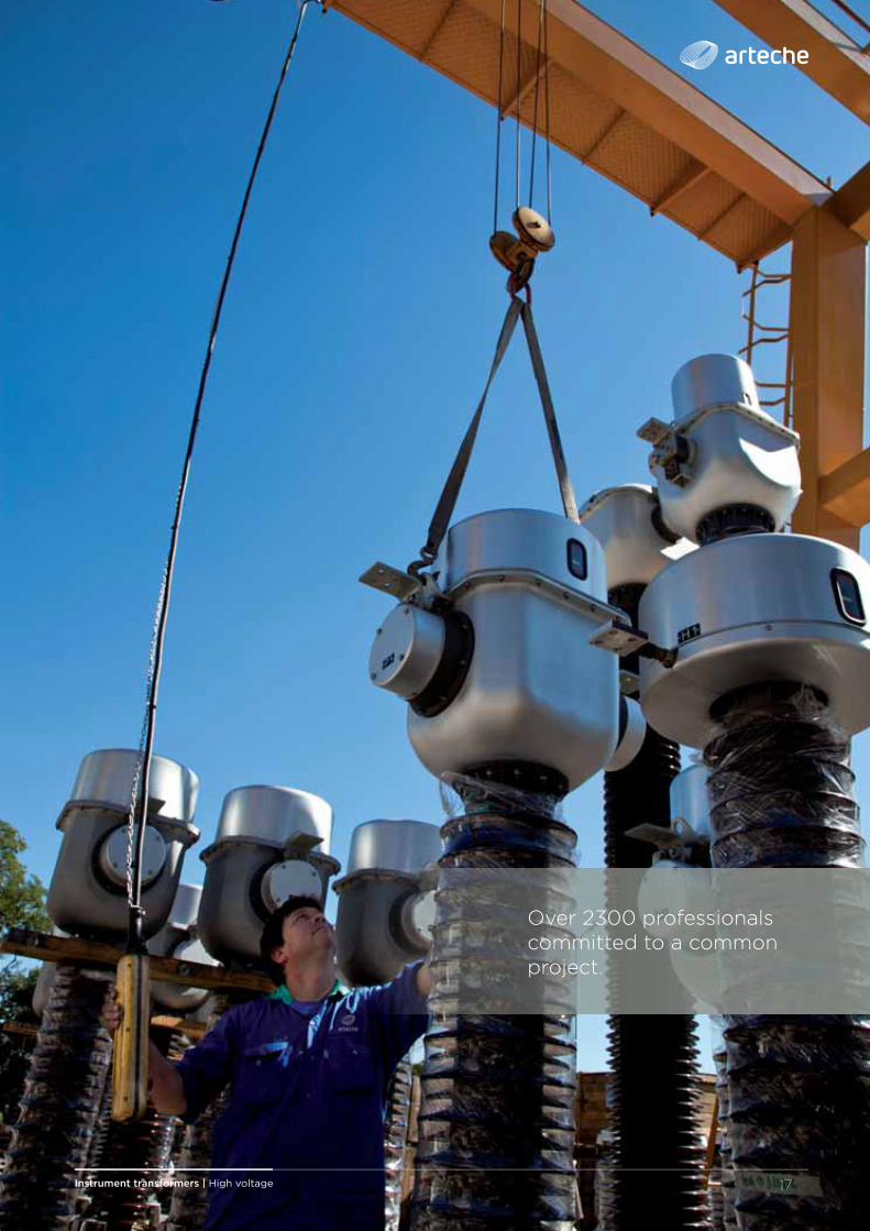
Over 2300 professionals committed to a common project.
18 Instrument transformers | High voltage
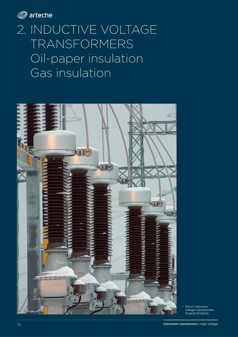
2. INDUCTIVE VOLTAGE TRANSFORMERS
Oil-paper insulation Gas insulation
› 123 kV Inductive voltage transformers. Fingrid (Finland).
19Instrument transformers | High voltage
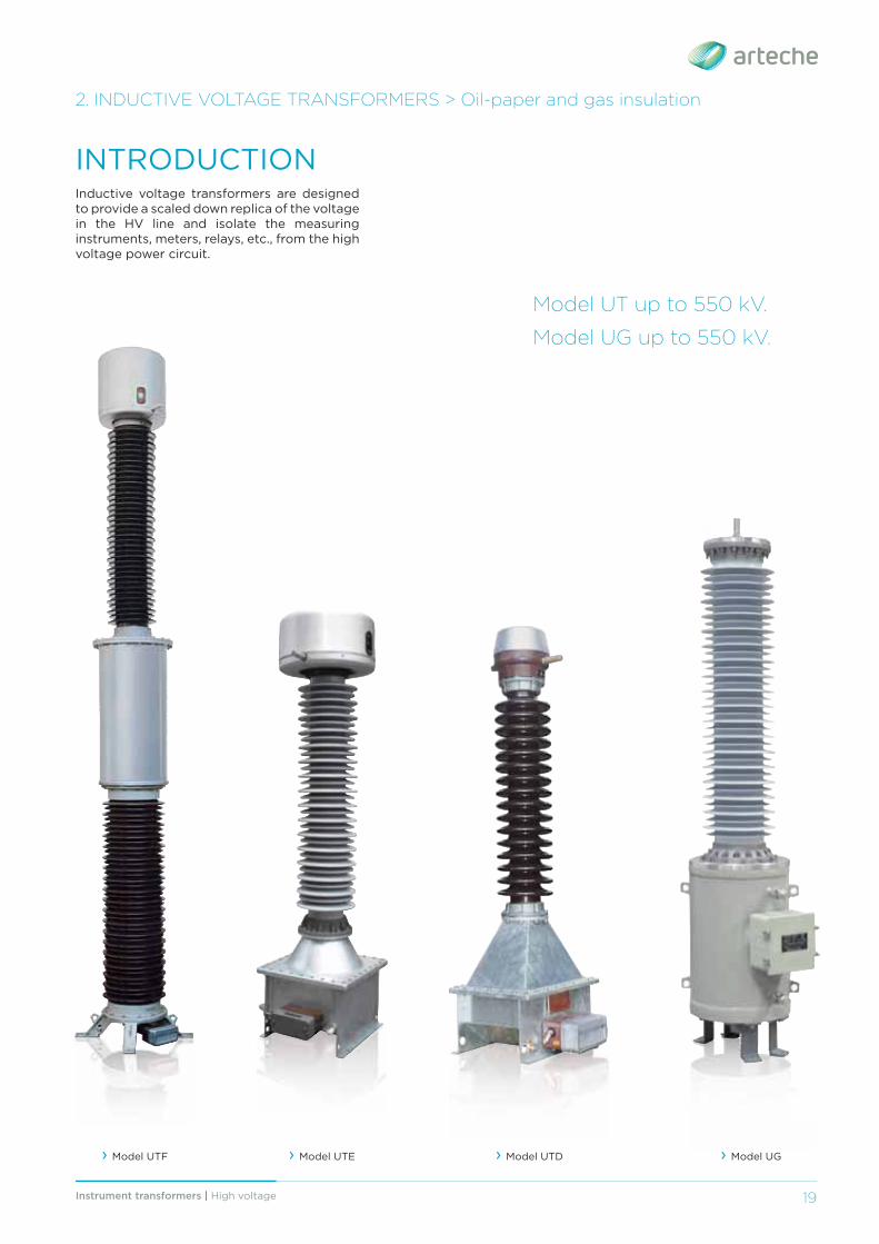
Inductive voltage transformers are designed to provide a scaled down replica of the voltage in the HV line and isolate the measuring instruments, meters, relays, etc., from the high voltage power circuit.
INTRODUCTION
2. INDUCTIVE VOLTAGE TRANSFORMERS > Oil-paper and gas insulation
› Model UTF › Model UTE › Model UTD › Model UG
Model UT up to 550 kV.
Model UG up to 550 kV.
Instrument transformers | High voltage20
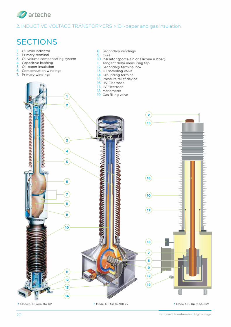
SECTIONS1. Oil level indicator2. Primary terminal3. Oil volume compensating system4. Capacitive bushing5. Oil-paper insulation6. Compensation windings7. Primary windings
8. Secondary windings9. Core10. Insulator (porcelain or silicone rubber)11. Tangent delta measuring tap12. Secondary terminal box13. Oil sampling valve14. Grounding terminal15. Pressure relief device16. HV Electrode17. LV Electrode18. Manometer19. Gas fi lling valve
2. INDUCTIVE VOLTAGE TRANSFORMERS > Oil-paper and gas insulation
› Model UT. Up to 300 kV
1
2
3
4
5
6
7
8
9
13
10
14
11
12
8
› Model UT. From 362 kV
7
9
16
10
12
2
17
19
15
› Model UG. Up to 550 kV
18
21Instrument transformers | High voltage 21
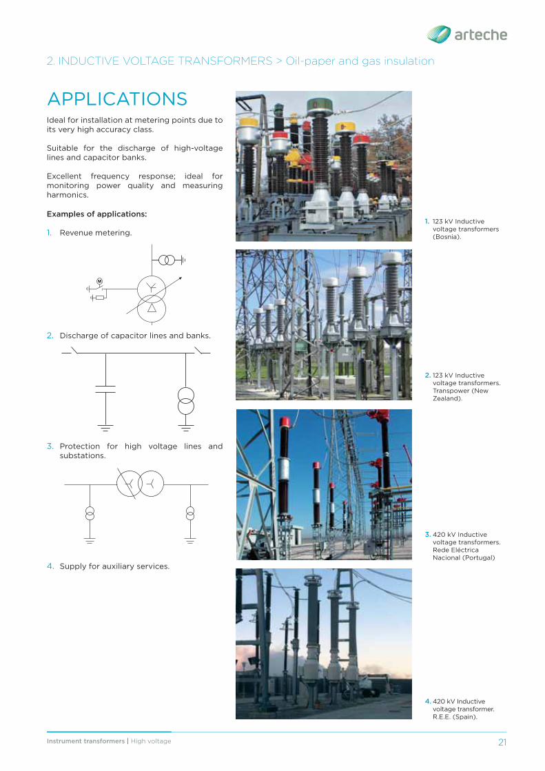
Examples of applications:
1. Revenue metering.
2. Discharge of capacitor lines and banks.
3. Protection for high voltage lines and substations.
4. Supply for auxiliary services.
APPLICATIONSIdeal for installation at metering points due to its very high accuracy class.
Suitable for the discharge of high-voltage lines and capacitor banks.
Excellent frequency response; ideal for monitoring power quality and measuring harmonics.
M
1. 123 kV Inductive voltage transformers (Bosnia).
2. 123 kV Inductive voltage transformers. Transpower (New Zealand).
3. 420 kV Inductive voltage transformers. Rede Eléctrica Nacional (Portugal)
4. 420 kV Inductive voltage transformer. R.E.E. (Spain).
2. INDUCTIVE VOLTAGE TRANSFORMERS > Oil-paper and gas insulation
Instrument transformers | High voltage22
Voltage transformers can have several secondary windings for metering and/or protection. The primary winding and all the secondary windings are wound around the same core, which is loaded with the total burden.
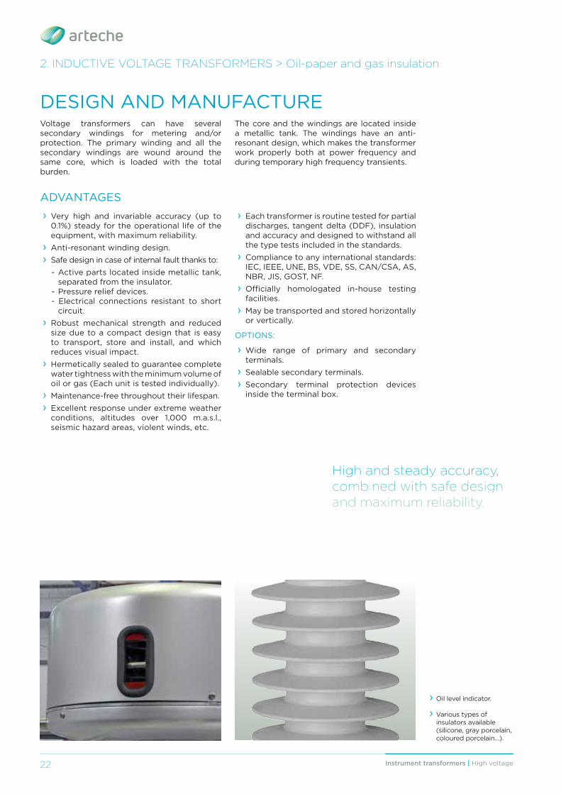
› Oil level indicator.
› Various types of insulators available (silicone, gray porcelain, coloured porcelain…).
HHHHHiiiiiggggghhhhh aaaannnnddddd ssssttttteeeeaaaadddddyyyyy aaaaccccccccuuuurrrraaaaccccyyyyy,, cccooommmbbbbiiiinnneeedddd wwwiiiitttthhhh sssaaaffffeee ddddeeesssiiiigggggnnn aaannddddd mmaaaxxiiiimmuuumm rreeelllliiiiaaabbbbbiiiilllliiiittttyyy.
2. INDUCTIVE VOLTAGE TRANSFORMERS > Oil-paper and gas insulation
ADVANTAGES
DESIGN AND MANUFACTURE
› Very high and invariable accuracy (up to 0.1%) steady for the operational life of the equipment, with maximum reliability.
› Anti-resonant winding design. › Safe design in case of internal fault thanks to:
- Active parts located inside metallic tank, separated from the insulator.
- Pressure relief devices.- Electrical connections resistant to short
circuit. › Robust mechanical strength and reduced size due to a compact design that is easy to transport, store and install, and which reduces visual impact.
› Hermetically sealed to guarantee complete water tightness with the minimum volume of oil or gas (Each unit is tested individually).
› Maintenance-free throughout their lifespan. › Excellent response under extreme weather conditions, altitudes over 1,000 m.a.s.l., seismic hazard areas, violent winds, etc.
› Each transformer is routine tested for partial discharges, tangent delta (DDF), insulation and accuracy and designed to withstand all the type tests included in the standards.
› Compliance to any international standards: IEC, IEEE, UNE, BS, VDE, SS, CAN/CSA, AS, NBR, JIS, GOST, NF.
› Offi cially homologated in-house testing facilities.
› May be transported and stored horizontally or vertically.
OPTIONS:
› Wide range of primary and secondary terminals.
› Sealable secondary terminals. › Secondary terminal protection devices inside the terminal box.
The core and the windings are located inside a metallic tank. The windings have an anti-resonant design, which makes the transformer work properly both at power frequency and during temporary high frequency transients.
23Instrument transformers | High voltage 23
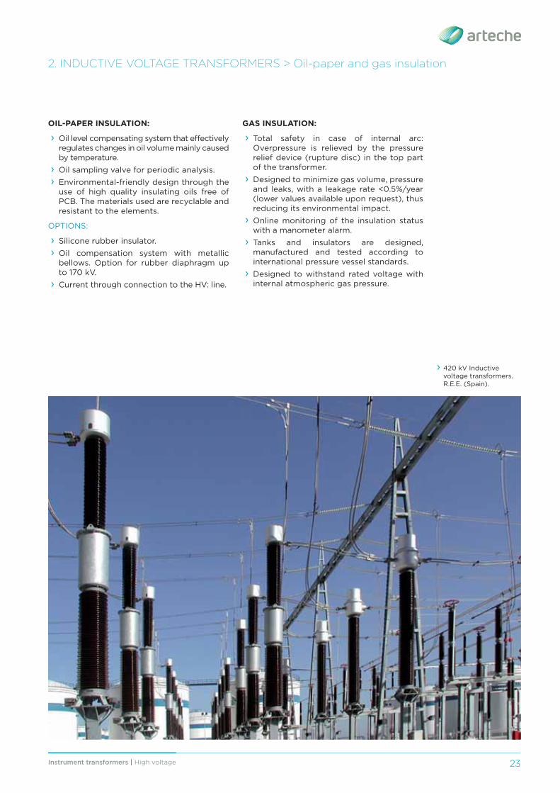
› 420 kV Inductive voltage transformers. R.E.E. (Spain).
2. INDUCTIVE VOLTAGE TRANSFORMERS > Oil-paper and gas insulation
OIL-PAPER INSULATION:
› Oil level compensating system that eff ectively regulates changes in oil volume mainly caused by temperature.
› Oil sampling valve for periodic analysis. › Environmental-friendly design through the use of high quality insulating oils free of PCB. The materials used are recyclable and resistant to the elements.
OPTIONS:
› Silicone rubber insulator. › Oil compensation system with metallic bellows. Option for rubber diaphragm up to 170 kV.
› Current through connection to the HV: line.
GAS INSULATION:
› Total safety in case of internal arc: Overpressure is relieved by the pressure relief device (rupture disc) in the top part of the transformer.
› Designed to minimize gas volume, pressure and leaks, with a leakage rate <0.5%/year (lower values available upon request), thus reducing its environmental impact.
› Online monitoring of the insulation status with a manometer alarm.
› Tanks and insulators are designed, manufactured and tested according to international pressure vessel standards.
› Designed to withstand rated voltage with internal atmospheric gas pressure.

Instrument transformers | High voltage24
RANGEARTECHE inductive voltage transformers are named with the letters (UT oil-paper or UG gas) followed by 1 additional letter (oil paper only), and 2 or 3 numbers indicating the maximum voltage of the network for which they are designed.
The table on the next page shows the range of both types of transformers currently manufactured by ARTECHE. These characteristics are merely indicative; ARTECHE can manufacture inductive voltage transformers to comply with any domestic or international standard.
Standard accuracy classes and burdens:
› According to IEC standards 100 VA Class 0,2 / 3P 250 VA Class 0,5 / 3P › According to IEEE standards
0.3 WXYZ 1.2 WXYZ, ZZHigher accuracy classes and burdens available.
› 123 kV Inductive voltage transformers. Electronet Services (New Zealand).
› 420 kV Inductive voltage transformers.Elia (Belgium).
› Model UTF from 362 kV
› Models UTB/UTD/UTE/UTF/UTG up to 300 kV
2. INDUCTIVE VOLTAGE TRANSFORMERS > Oil-paper and gas insulation
› Model UG up to 550 kV
H
B
A
H
A
B
H
B
A
25Instrument transformers | High voltage 25
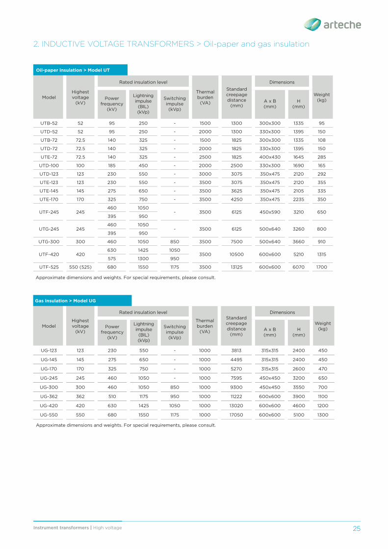
Oil-paper insulation > Model UT
ModelHighest voltage
(kV)
Rated insulation level
Thermal burden
(VA)
Standard creepage distance
(mm)
Dimensions
Weight(kg)Power
frequency (kV)
Lightning impulse
(BIL) (kVp)
Switching impulse (kVp)
A x B(mm)
H(mm)
UTB-52 52 95 250 - 1500 1300 300x300 1335 95
UTD-52 52 95 250 - 2000 1300 330x300 1395 150
UTB-72 72.5 140 325 - 1500 1825 300x300 1335 108
UTD-72 72.5 140 325 - 2000 1825 330x300 1395 150
UTE-72 72.5 140 325 - 2500 1825 400x430 1645 285
UTD-100 100 185 450 - 2000 2500 330x300 1690 165
UTD-123 123 230 550 - 3000 3075 350x475 2120 292
UTE-123 123 230 550 - 3500 3075 350x475 2120 355
UTE-145 145 275 650 - 3500 3625 350x475 2105 335
UTE-170 170 325 750 - 3500 4250 350x475 2235 350
UTF-245 245460 1050
- 3500 6125 450x590 3210 650395 950
UTG-245 245460 1050
- 3500 6125 500x640 3260 800395 950
UTG-300 300 460 1050 850 3500 7500 500x640 3660 910
UTF-420 420630 1425 1050
3500 10500 600x600 5210 1315575 1300 950
UTF-525 550 (525) 680 1550 1175 3500 13125 600x600 6070 1700
Approximate dimensions and weights. For special requirements, please consult.
2. INDUCTIVE VOLTAGE TRANSFORMERS > Oil-paper and gas insulation
Gas insulation > Model UG
ModelHighest voltage
(kV)
Rated insulation level
Thermal burden
(VA)
Standard creepage distance
(mm)
Dimensions
Weight(kg)Power
frequency (kV)
Lightning impulse
(BIL) (kVp)
Switching impulse (kVp)
A x B(mm)
H(mm)
UG-123 123 230 550 - 1000 3813 315x315 2400 450
UG-145 145 275 650 - 1000 4495 315x315 2400 450
UG-170 170 325 750 - 1000 5270 315x315 2600 470
UG-245 245 460 1050 - 1000 7595 450x450 3200 650
UG-300 300 460 1050 850 1000 9300 450x450 3550 700
UG-362 362 510 1175 950 1000 11222 600x600 3900 1100
UG-420 420 630 1425 1050 1000 13020 600x600 4600 1200
UG-550 550 680 1550 1175 1000 17050 600x600 5100 1300
Approximate dimensions and weights. For special requirements, please consult.
26 Instrument transformers | High voltage
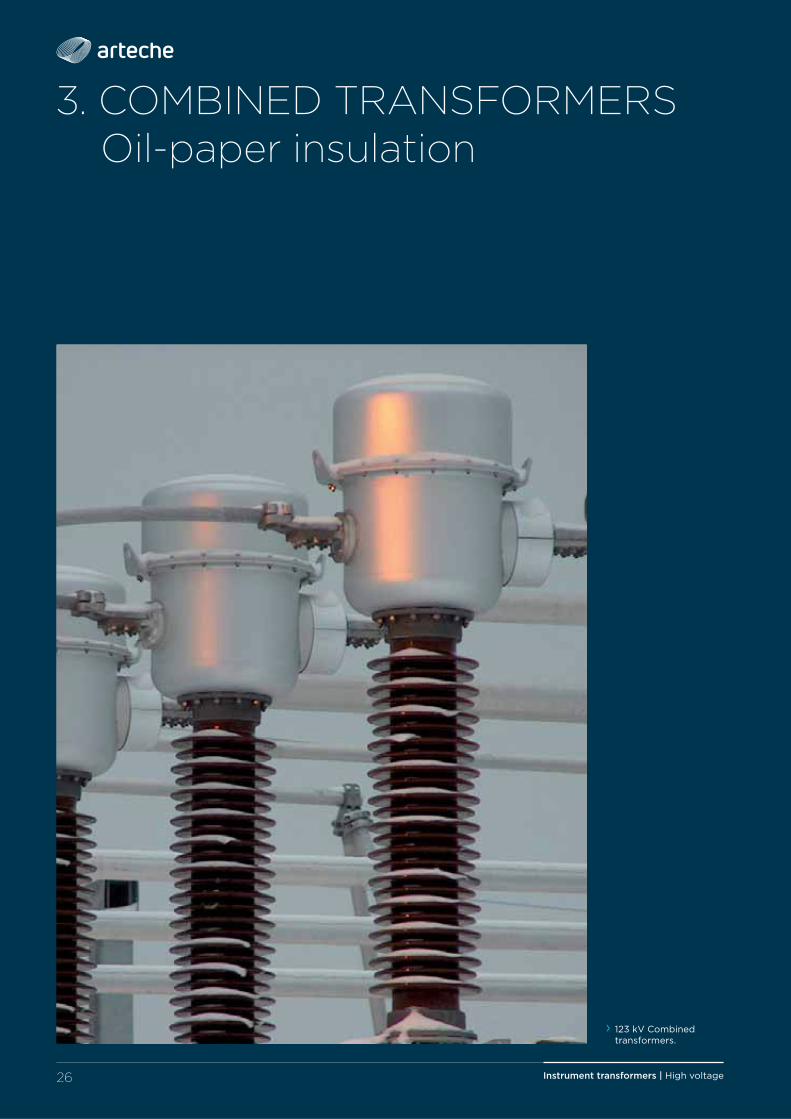
3. COMBINED TRANSFORMERS Oil-paper insulation
› 123 kV Combined transformers.
27Instrument transformers | High voltage
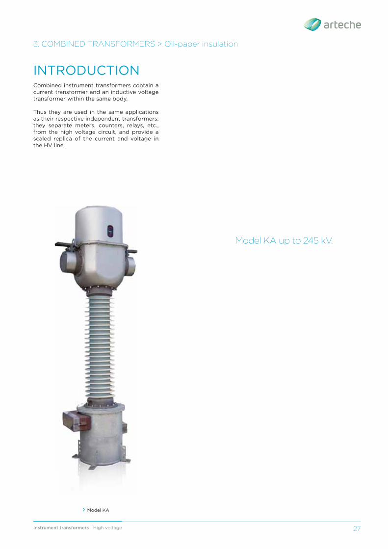
Combined instrument transformers contain a current transformer and an inductive voltage transformer within the same body.
Thus they are used in the same applications as their respective independent transformers; they separate meters, counters, relays, etc., from the high voltage circuit, and provide a scaled replica of the current and voltage in the HV line.
INTRODUCTION
Model KA up to 245 kV.
3. COMBINED TRANSFORMERS > Oil-paper insulation
› Model KA
Instrument transformers | High voltage28
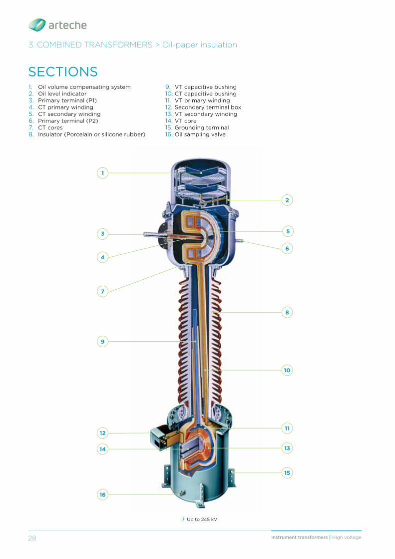
› Up to 245 kV
1
2
3
6
7
8
9
13
10
14
1112
5
SECTIONS1. Oil volume compensating system2. Oil level indicator3. Primary terminal (P1)4. CT primary winding5. CT secondary winding6. Primary terminal (P2)7. CT cores8. Insulator (Porcelain or silicone rubber)
9. VT capacitive bushing10. CT capacitive bushing11. VT primary winding12. Secondary terminal box13. VT secondary winding14. VT core15. Grounding terminal16. Oil sampling valve
3. COMBINED TRANSFORMERS > Oil-paper insulation
4
15
16
29Instrument transformers | High voltage 29
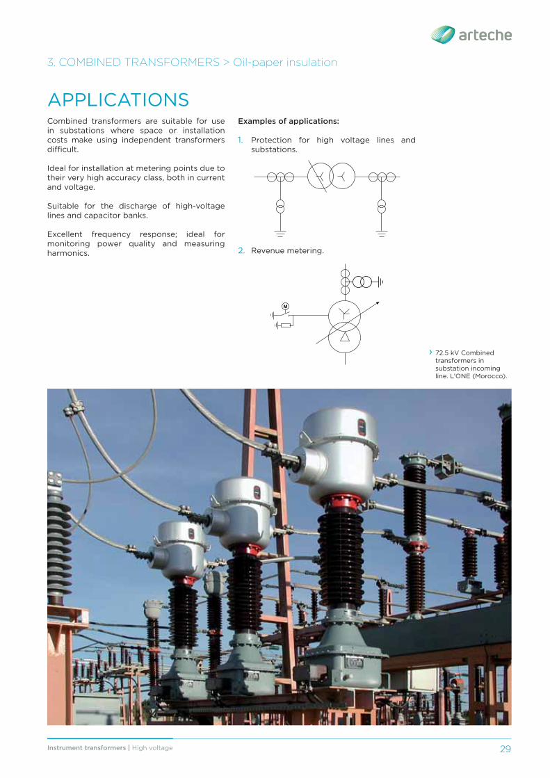
APPLICATIONSCombined transformers are suitable for use in substations where space or installation costs make using independent transformers diffi cult.
Ideal for installation at metering points due to their very high accuracy class, both in current and voltage.
Suitable for the discharge of high-voltage lines and capacitor banks.
Excellent frequency response; ideal for monitoring power quality and measuring harmonics.
3. COMBINED TRANSFORMERS > Oil-paper insulation
› 72.5 kV Combined transformers in substation incoming line. L’ONE (Morocco).
Examples of applications:
1. Protection for high voltage lines and substations.
2. Revenue metering.
M
Instrument transformers | High voltage30
Combined transformers mirror the manufacturing characteristics of current transformers (CA type) and inductive voltage transformers (UT type).
The CT active parts are located in the top part inside a metal box that acts as a low-voltage shield; the main oil-paper insulation is wrapped around it, ending up with a high-voltage shield. The primary conductor can be a pass-through bar (with or without external reclosings) or a winding, depending on the case. The secondary cables run through an oil-paper insulated capacitive bushing with several shields for proper electrical fi eld distribution.
Voltage transformers can have several secondary windings for metering and/or protection. The primary winding and all the secondary windings are wound around the same core, which is loaded with all the burden.
The core and the windings are located inside a metallic tank. The windings have an anti-resonant design, which makes the transformer work properly both at power frequency and during temporary high frequency transients.
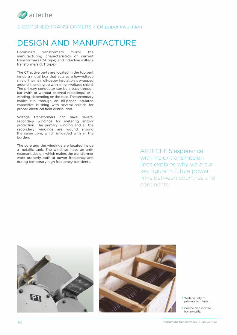
› Wide variety of primary terminals.
› Can be transported horizontally.
AARRTTEECCHHEE’SS eexxpppeerriieennccee wwiiittthhh mmaajjjoorr tttrraannssmmiiissssiiioonn llliiinnneeesss eeexxxppplllaaaiiinnnsss wwwhhhyyy wwweee aaarrreee aaa kkeyy fifi ggure iin ffutture ppower llliiinnnkkksss bbbeeetttwwweeeeeennn cccooouuunnntttrrriiieeesss aaannnddd ccoonnttiiinneennttss.
3. COMBINED TRANSFORMERS > Oil-paper insulation
DESIGN AND MANUFACTURE
31Instrument transformers | High voltage 31
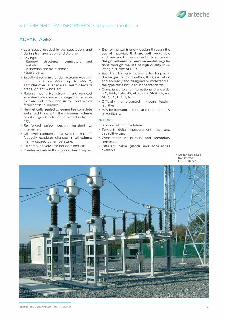
› 123 kV combined transformers. ESB (Ireland).
3. COMBINED TRANSFORMERS > Oil-paper insulation
› Less space needed in the substation, and during transportation and storage.
› Savings:- Support structures, connectors and
installation time.- Inspection and maintenance.- Spare parts.
› Excellent response under extreme weather conditions (from -55°C; up to +55°C), altitudes over 1,000 m.a.s.l., seismic hazard areas, violent winds, etc.
› Robust mechanical strength and reduced size due to a compact design that is easy to transport, store and install, and which reduces visual impact.
› Hermetically sealed to guarantee complete water tightness with the minimum volume of oil or gas (Each unit is tested individu-ally).
› Reinforced safety design, resistant to internal arc.
› Oil level compensating system that ef-fectively regulates changes in oil volume mainly caused by temperature.
› Oil sampling valve for periodic analysis. › Maintenance-free throughout their lifespan.
ADVANTAGES
› Environmental-friendly design through the use of materials that are both recyclable and resistant to the elements. Its advanced design adheres to environmental regula-tions through the use of high quality insu-lating oils, free of PCB.
› Each transformer is routine tested for partial discharges, tangent delta (DDF), insulation and accuracy and designed to withstand all the type tests included in the standards.
› Compliance to any international standards: IEC, IEEE, UNE, BS, VDE, SS, CAN/CSA, AS, NBR, JIS, GOST, NF…
› Offi cially homologated in-house testing facilities.
› May be transported and stored horizontally or vertically.
OPTIONS: › Silicone rubber insulation. › Tangent delta measurement tap and capacitive tap.
› Wide range of primary and secondary terminals.
› Diff erent cable glands and accessories available.
Instrument transformers | High voltage32
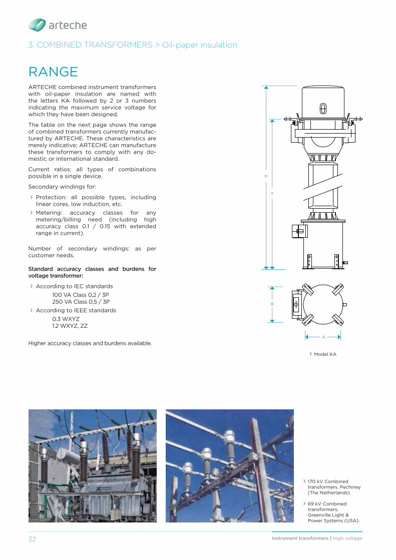
RANGEARTECHE combined instrument transformers with oil-paper insulation are named with the letters KA followed by 2 or 3 numbers indicating the maximum service voltage for which they have been designed.
The table on the next page shows the range of combined transformers currently manufac-tured by ARTECHE. These characteristics are merely indicative; ARTECHE can manufacture these transformers to comply with any do-mestic or international standard.
Current ratios: all types of combinations possible in a single device.
Secondary windings for:
› Protection: all possible types, including linear cores, low induction, etc.
› Metering: accuracy classes for any metering/billing need (including high accuracy class 0.1 / 0.15 with extended range in current).
Number of secondary windings: as per customer needs.
Standard accuracy classes and burdens for voltage transformer:
› According to IEC standards 100 VA Class 0,2 / 3P 250 VA Class 0,5 / 3P › According to IEEE standards
0.3 WXYZ 1.2 WXYZ, ZZ
Higher accuracy classes and burdens available.
H
T
A
› Model KA
3. COMBINED TRANSFORMERS > Oil-paper insulation
B
› 170 kV Combined transformers. Pechiney (The Netherlands).
› 69 kV Combined transformers. Greenville Light & Power Systems (USA).
33Instrument transformers | High voltage 33
3. COMBINED TRANSFORMERS > Oil-paper insulation
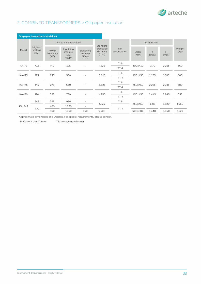
Oil-paper insulation > Model KA
ModelHighest voltage
(kV)
Rated insulation levelStandard creepage distance
(mm)
No. secondaries*
Dimensions
Weight(kg)Power
frequency (kV)
Lightning impulse
(BIL) (kVp)
Switching impulse (kVp)
AXB(mm)
T(mm)
H(mm)
KA-72 72,5 140 325 - 1.825TI 6
400x430 1.770 2.235 360TT 4
KA-123 123 230 550 - 3.625TI 6
450x450 2.285 2.785 580TT 4
KA-145 145 275 650 - 3.625TI 6
450x450 2.285 2.785 580TT 4
KA-170 170 325 750 - 4.250TI 6
450x450 2.445 2.945 755TT 4
KA-245
245 395 950 -6.125
TI 6450x450 3.185 3.820 1.050
300460 1.050 -
TT 4460 1.050 850 7.500 600x600 4.340 5.050 1.520
Approximate dimensions and weights. For special requirements, please consult.
*TI: Current transformer *TT: Voltage transformer
34 Instrument transformers | High voltage
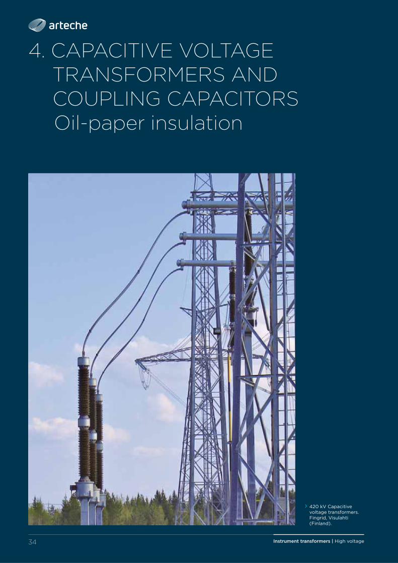
4. CAPACITIVE VOLTAGE TRANSFORMERS AND COUPLING CAPACITORS
Oil-paper insulation
› 420 kV Capacitive voltage transformers. Fingrid, Visulahti (Finland).
35Instrument transformers | High voltage
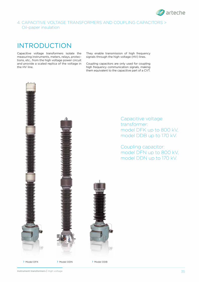
Capacitive voltage transformers isolate the measuring instruments, meters, relays, protec-tions, etc., from the high voltage power circuit and provide a scaled replica of the voltage in the HV line.
› Model DFK
INTRODUCTION
Capacitive voltagetransformer:model DFK up to 800 kV,model DDB up to 170 kV.
Coupling capacitor: model DFN up to 800 kV,model DDN up to 170 kV.
4. CAPACITIVE VOLTAGE TRANSFORMERS AND COUPLING CAPACITORS > Oil-paper insulation
› Model DDN › Model DDB
They enable transmission of high frequency signals through the high voltage (HV) lines.
Coupling capacitors are only used for coupling high frequency communication signals, making them equivalent to the capacitive part of a CVT.
Instrument transformers | High voltage36
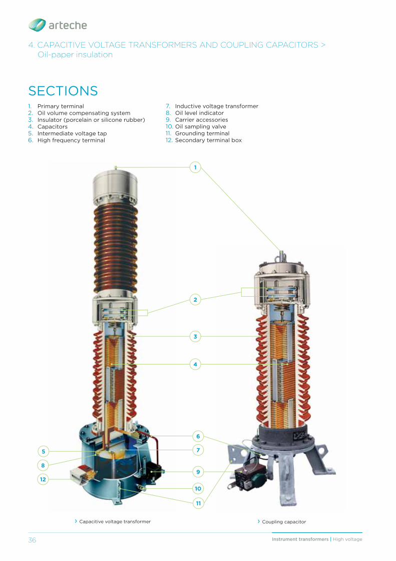
› Coupling capacitor
1
2
3
4
5
6
7
9
10
11
12
8
› Capacitive voltage transformer
SECTIONS1. Primary terminal2. Oil volume compensating system3. Insulator (porcelain or silicone rubber)4. Capacitors5. Intermediate voltage tap6. High frequency terminal
7. Inductive voltage transformer8. Oil level indicator9. Carrier accessories10. Oil sampling valve11. Grounding terminal12. Secondary terminal box
4. CAPACITIVE VOLTAGE TRANSFORMERS AND COUPLING CAPACITORS > Oil-paper insulation
37Instrument transformers | High voltage 37
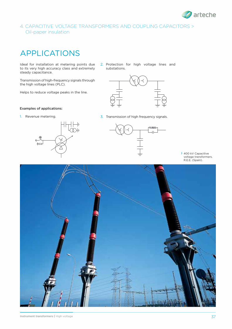
APPLICATIONSIdeal for installation at metering points due to its very high accuracy class and extremely steady capacitance.
Transmission of high-frequency signals through the high voltage lines (PLC).
Helps to reduce voltage peaks in the line.
› 400 kV Capacitive voltage transformers. R.E.E. (Spain).
4. CAPACITIVE VOLTAGE TRANSFORMERS AND COUPLING CAPACITORS > Oil-paper insulation
Examples of applications:
1. Revenue metering.
2. Protection for high voltage lines and substations.
3. Transmission of high frequency signals.
M
Instrument transformers | High voltage38
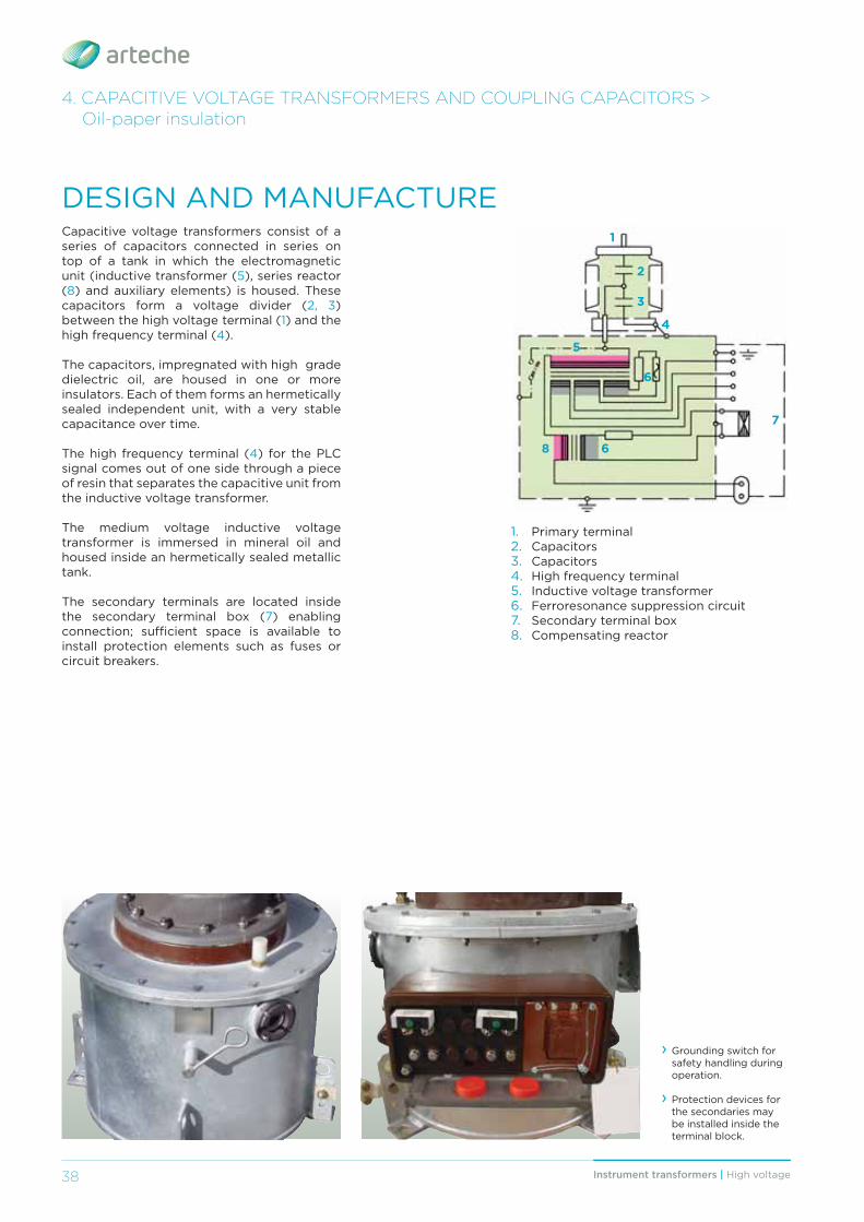
Capacitive voltage transformers consist of a series of capacitors connected in series on top of a tank in which the electromagnetic unit (inductive transformer (5), series reactor (8) and auxiliary elements) is housed. These capacitors form a voltage divider (2, 3) between the high voltage terminal (1) and the high frequency terminal (4).
The capacitors, impregnated with high grade dielectric oil, are housed in one or more insulators. Each of them forms an hermetically sealed independent unit, with a very stable capacitance over time. The high frequency terminal (4) for the PLC signal comes out of one side through a piece of resin that separates the capacitive unit from the inductive voltage transformer.
The medium voltage inductive voltage transformer is immersed in mineral oil and housed inside an hermetically sealed metallic tank.
The secondary terminals are located inside the secondary terminal box (7) enabling connection; suffi cient space is available to install protection elements such as fuses or circuit breakers.
› Grounding switch for safety handling during operation.
› Protection devices for the secondaries may be installed inside the terminal block.
DESIGN AND MANUFACTURE
2
1
3
5
4
6
6
7
8
1. Primary terminal2. Capacitors3. Capacitors4. High frequency terminal5. Inductive voltage transformer6. Ferroresonance suppression circuit7. Secondary terminal box8. Compensating reactor
4. CAPACITIVE VOLTAGE TRANSFORMERS AND COUPLING CAPACITORS > Oil-paper insulation
39Instrument transformers | High voltage 39
› High stability of capacity, and therefore of accuracy.
› Reliable ferroresonance suppression sys-tem that does not aff ect transient response or accuracy.
› Excellent mechanical resistance to seismic forces.
› Pressure relief device to guarantee maxi-mum safety.
› Robust mechanical strength and reduced size due to a compact design that is easy to transport, store and install, and which reduces visual impact.
› Hermetically sealed to guarantee complete water tightness with the minimum volume of oil or gas (Each unit is tested individually).
› Oil level compensating system that eff ec-tively regulates changes in oil volume.
› Maintenance-free throughout their lifespan. › Environmental-friendly design through the use of materials that are recyclable and resistant to the elements. Its advanced de-sign adheres to environmental regulations through the use of high quality insulating oils, free of PCB.
› Excellent response under extreme weather conditions (from -55°C; up to +55°C), altitudes over 1,000 m.a.s.l., seismic hazard areas, violent winds, etc.
› Each transformer is routine tested for partial discharges, tangent delta (DDF), insulation and accuracy and designed to withstand all the type tests included in the standards.
› Compliance to any international standards: IEC, IEEE, UNE, BS, VDE, SS, CAN/CSA, AS, NBR, JIS, GOST, NF…
› Offi cially homologated in-house testing facilities.
OPTIONS:
› Silicone rubber insulation. › Carrier accessories. › Ground switch for the inductive part. › Wide range of primary and secondary terminals.
› Sealable secondary terminals. › Line traps can be mounted on top of the CVT.
› Diff erent cable glands and accessories available.
› Wide range of capacitances. › Secondary terminal protection devices inside the terminal box.
ADVANTAGES
MMMMMaaaaaxxxxxiiiiimmmmmuuuuummmmm sssssaaaaafffffeeeeetttttyyyyyy aaaaannnnnddddd rrrrreeeeelllllliiiiiaaaaabbbbbbiiiiilllllliiiiitttttyyyyyy wwwwwiiiiittttthhhhhhiiiiinnnnn aaaaacccuuussstttooommm-mmmaaadddeee dddeeesssiiigggnnn.
4. CAPACITIVE VOLTAGE TRANSFORMERS AND COUPLING CAPACITORS > Oil-paper insulation
Instrument transformers | High voltage40
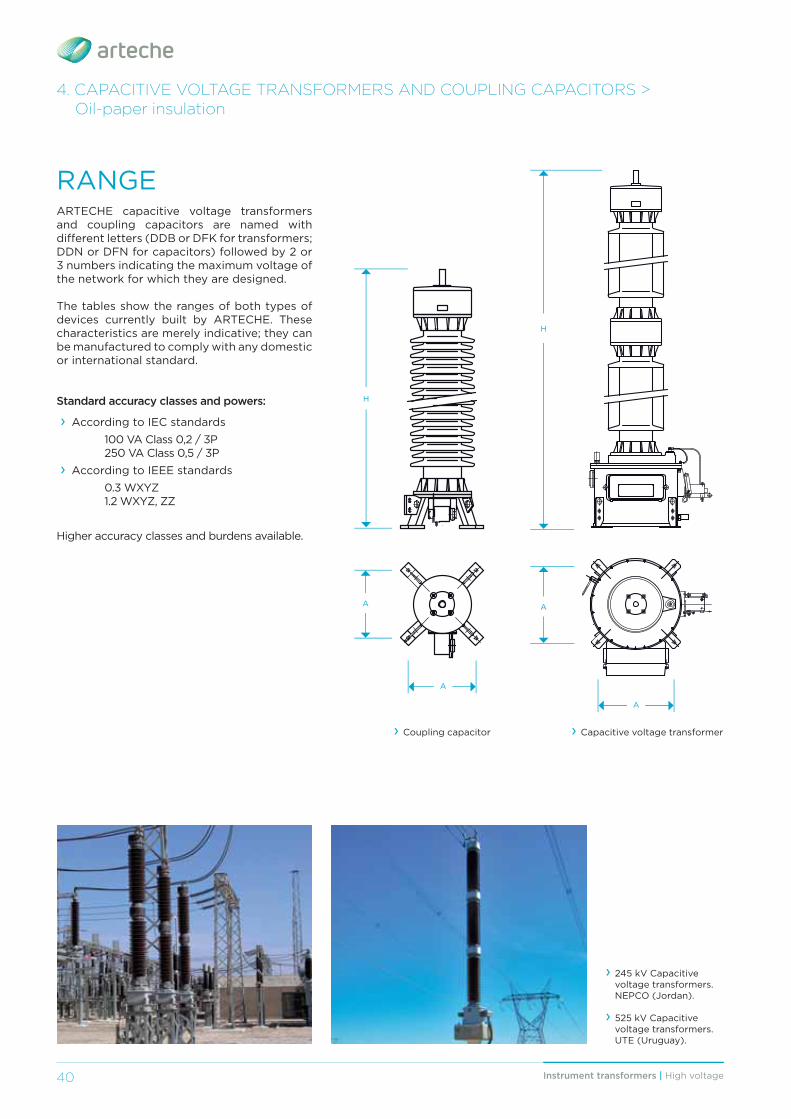
RANGEARTECHE capacitive voltage transformers and coupling capacitors are named with diff erent letters (DDB or DFK for transformers; DDN or DFN for capacitors) followed by 2 or 3 numbers indicating the maximum voltage of the network for which they are designed.
The tables show the ranges of both types of devices currently built by ARTECHE. These characteristics are merely indicative; they can be manufactured to comply with any domestic or international standard.
Standard accuracy classes and powers:
› According to IEC standards 100 VA Class 0,2 / 3P 250 VA Class 0,5 / 3P › According to IEEE standards
0.3 WXYZ 1.2 WXYZ, ZZ
Higher accuracy classes and burdens available.
› 245 kV Capacitive voltage transformers. NEPCO (Jordan).
› 525 kV Capacitive voltage transformers. UTE (Uruguay).
H
H
A
A
› Coupling capacitor › Capacitive voltage transformer
A
A
4. CAPACITIVE VOLTAGE TRANSFORMERS AND COUPLING CAPACITORS > Oil-paper insulation
41Instrument transformers | High voltage 41
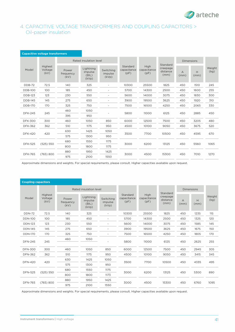
Capacitive voltage transformers
ModelHighest Voltage
(kV)
Rated insulation level
Standard capacitance
(pF)
High capacitance
(pF)
Standard creepage distance
(mm)
Dimensions
Weight (kg)Power
frequency (kV)
Lightning impulse
(BIL) (kVp)
Switching impulse (kVp)
A(mm)
H(mm)
DDB-72 72.5 140 325 - 10300 25500 1825 450 1510 245
DDB-100 100 185 450 - 5700 14300 2500 450 1600 255
DDB-123 123 230 550 - 5600 14000 3075 450 1830 300
DDB-145 145 275 650 - 3900 19500 3625 450 1920 310
DDB-170 170 325 750 - 7500 16500 4250 450 2065 330
DFK-245 245460 1050
- 5800 11000 6125 450 2885 450395 950
DFK-300 300 460 1050 850 6000 12500 7500 450 3205 480
DFK-362 362 510 1175 950 4500 10100 9050 450 3675 520
DFK-420 420630 1425 1050
3500 7700 10500 450 4595 670575 1300 950
DFK-525 (525) 550680 1550 1175
3000 6200 13125 450 5560 1065800 1800 1175
DFK-765 (765) 800880 1950 1425
3000 4500 15300 450 7010 1270975 2100 1550
Approximate dimensions and weights. For special requirements, please consult. Higher capacities available upon request.
Coupling capacitors
ModelHighest Voltage
(kV)
Rated insulation level
Standard capacitance
(pF)
High capacitance
(pF)
Standard creepage distance
(mm)
Dimensions
Weight (kg)Power
frequency (kV)
Lightning impulse
(BIL) (kVp)
Switching impulse (kVp)
A(mm)
H(mm)
DDN-72 72.5 140 325 - 10300 25500 1825 450 1235 115
DDN-100 100 185 450 - 5700 14300 2500 450 1325 120
DDN-123 123 230 550 - 5600 14000 3075 450 1585 145
DDN-145 145 275 650 - 3900 19500 3625 450 1675 150
DDN-170 170 325 750 - 7500 16500 4250 450 1805 170
DFN-245 245460 1050
- 5800 11000 6125 450 2625 255
DFN-300 300 460 1050 850 6000 12500 7500 450 2945 305
DFN-362 362 510 1175 950 4500 10100 9050 450 3415 345
DFN-420 420630 1425 1050
3500 7700 10500 450 4335 495575 1300 950
DFN-525 (525) 550680 1550 1175
3000 6200 13125 450 5300 890800 1800 1173
DFN-765 (765) 800880 1950 1425
3000 4500 15300 450 6760 1095975 2100 1550
Approximate dimensions and weights. For special requirements, please consult. Higher capacities available upon request.
4. CAPACITIVE VOLTAGE TRANSFORMERS AND COUPLING CAPACITORS > Oil-paper insulation
42 Instrument transformers | High voltage
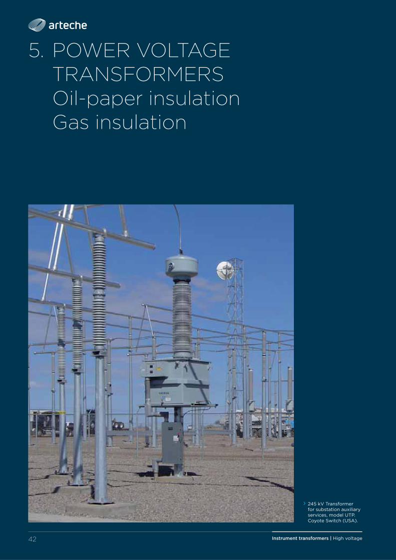
5. POWER VOLTAGE TRANSFORMERS Oil-paper insulation Gas insulation
› 245 kV Transformer for substation auxiliary services, model UTP. Coyote Switch (USA).
43Instrument transformers | High voltage
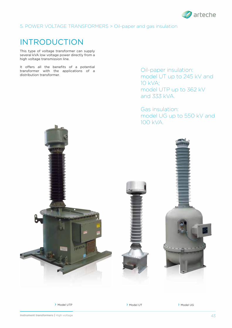
› Model UTP
5. POWER VOLTAGE TRANSFORMERS > Oil-paper and gas insulation
Oil-paper insulation: model UT up to 245 kV and 10 kVA; model UTP up to 362 kV and 333 kVA.
Gas insulation:model UG up to 550 kV and 100 kVA.
This type of voltage transformer can supply several kVA low voltage power directly from a high voltage transmission line. It off ers all the benefi ts of a potential transformer with the applications of a distribution transformer.
INTRODUCTION
› Model UT › Model UG
Instrument transformers | High voltage44
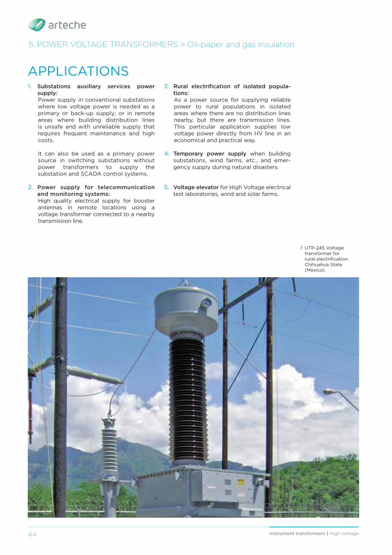
APPLICATIONS1. Substations auxiliary services power
supply:Power supply in conventional substations where low voltage power is needed as a primary or back-up supply; or in remote areas where building distribution lines is unsafe and with unreliable supply that requires frequent maintenance and high costs.
It can also be used as a primary power source in switching substations without power transformers to supply the substation and SCADA control systems.
2. Power supply for telecommunication and monitoring systems:High quality electrical supply for booster antennas in remote locations using a voltage transformer connected to a nearby transmission line.
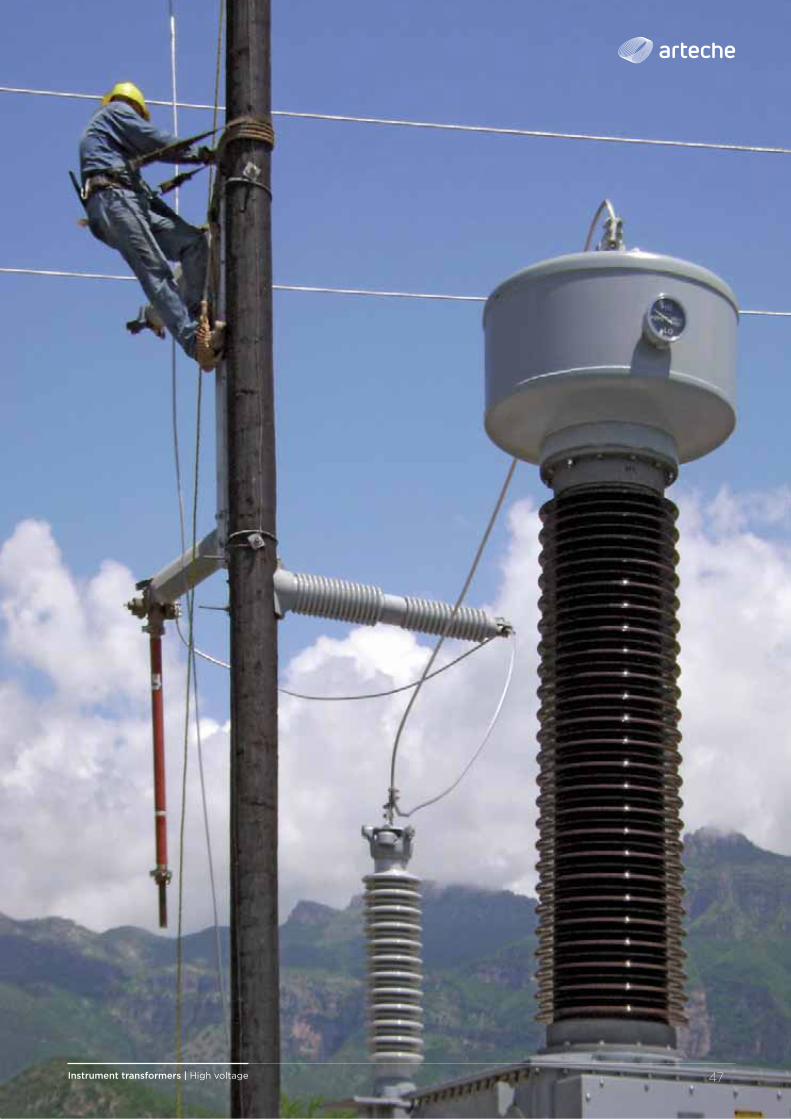
› UTP-245 Voltage transformer for rural electrifi cation. Chihuahua State (Mexico).
3. Rural electrifi cation of isolated popula-tions: As a power source for supplying reliable power to rural populations in isolated areas where there are no distribution lines nearby, but there are transmission lines. This particular application supplies low voltage power directly from HV line in an economical and practical way.
4. Temporary power supply when building substations, wind farms, etc., and emer-gency supply during natural disasters.
5. Voltage elevator for High Voltage electrical test laboratories, wind and solar farms.
5. POWER VOLTAGE TRANSFORMERS > Oil-paper and gas insulation
45Instrument transformers | High voltage 45
5. POWER VOLTAGE TRANSFORMERS > Oil-paper and gas insulation
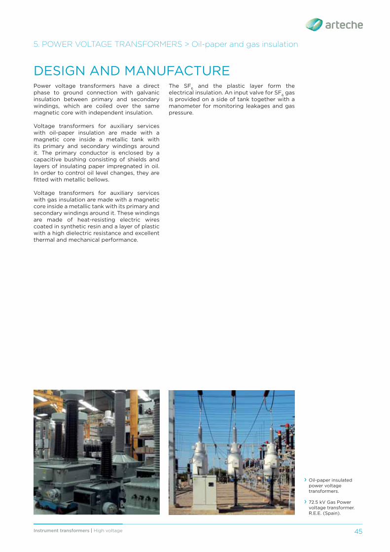
Power voltage transformers have a direct phase to ground connection with galvanic insulation between primary and secondary windings, which are coiled over the same magnetic core with independent insulation.
Voltage transformers for auxiliary services with oil-paper insulation are made with a magnetic core inside a metallic tank with its primary and secondary windings around it. The primary conductor is enclosed by a capacitive bushing consisting of shields and layers of insulating paper impregnated in oil. In order to control oil level changes, they are fi tted with metallic bellows.
Voltage transformers for auxiliary services with gas insulation are made with a magnetic core inside a metallic tank with its primary and secondary windings around it. These windings are made of heat-resisting electric wires coated in synthetic resin and a layer of plastic with a high dielectric resistance and excellent thermal and mechanical performance.
DESIGN AND MANUFACTURE
› Oil-paper insulated power voltage transformers.
› 72.5 kV Gas Power voltage transformer. R.E.E. (Spain).
The SF6 and the plastic layer form the electrical insulation. An input valve for SF6 gas is provided on a side of tank together with a manometer for monitoring leakages and gas pressure.
Instrument transformers | High voltage46
ARTECHE has developed a ppiioneeriingg ppiillot pprojjject iiinn ttthhhee SSStttaatttee oofff CCChhhiiihhhuuaahhhuuaa (((MMMeexxiiiccoo))) iiinn ccoollllllaabbboorraatttiiioonn wwwwiiiitttthhhh tttthhhheeee llllooooccccaaaallll ggggoooovvvveeeerrrrnnnnmmmmeeeennnntttt aaannnddd CCC.FFF.EEE. tttooo eeexxxttteeennnddd eellleecctttrriiiccaalll sseerrvviiiccee tttoo ttthhhee region’s rural population, using power voltage transformers, helping to reduce their isolation. This project has been awarded with the “Tomorrow’s Energy Prize” in the 2013 World Energy Congress (WEC).
ADVANTAGES
The conventional solutions used for applications mentioned on page 44 usually are a dedicated medium voltage line, diesel generators or the power transformer tertiary winding. ARTECHE’S power voltage transformer has the following advantages: › Highly reliable power source within the substation.
› Independent power supply, more fl exible as the user does not have to depend on third parties.
› Cost eff ective. › Maintenance-free throughout their lifespan. › Quick and fl exible solution › Release of the power transformer tertiary winding.
› Social benefi ts. Electrifi cation of isolated rural areas, emergency power after natural disasters…
In addition to the several advantages of this solution, there are also the common ones to ARTECHE instrument transformers range: › Wide range of designs meeting customer needs.
› Hermetically sealed to guarantee complete water tightness with the minimum volume of oil or gas (Each unit is tested individu-ally).
› Excellent response under extreme weather conditions, high altitudes, seismic hazard areas, violent winds, etc.
› Offi cially homologated in-house testing facilities.
› Each transformer is routine tested for partial discharges, tangent delta (DDF), insulation and accuracy and designed to withstand all the type tests included in the standards.
› Environmental-friendly design. The materi-als used are recyclable and resistant to the elements.
› May be transported and stored horizontally or vertically.
OPTIONS: › Additional secondaries for measuring and/or protection.
› Inner temperature monitoring sensor.
5. POWER VOLTAGE TRANSFORMERS > Oil-paper and gas insulation
OIL-PAPER: › Oil compensating system that eff ectively regulates changes in oil volume mainly caused by temperature.
› Oil sampling valve for periodic analysis.
OPTIONS: › Porcelain or silicone rubber insulator. › Over-pressure relief valve with connection capability to SCADA system.
› Terminal for main insulation monitoring (tangent δ measurement).
› Taps for voltage regulation. › Winding for secondary current measuring and protection.
› Single-phase/three-phase voltages in the secondary from a single HV phase.
GAS: › The silicone rubber insulator guarantees safety during transportation and service.
› Online monitoring of the insulation status with a manometer alarm.
› Pressure relief device (rupture disc) in the top part of the transformer.
Instrument transformers | High voltage 47
Instrument transformers | High voltage48
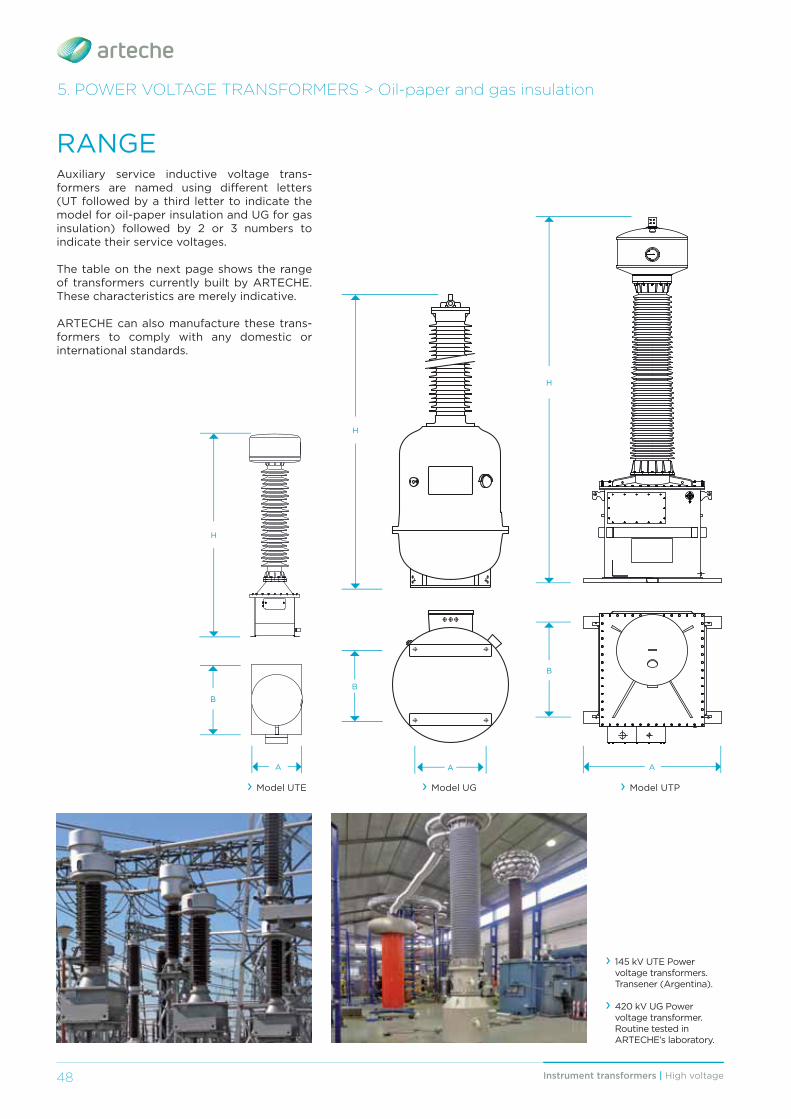
RANGEAuxiliary service inductive voltage trans-formers are named using diff erent letters (UT followed by a third letter to indicate the model for oil-paper insulation and UG for gas insulation) followed by 2 or 3 numbers to indicate their service voltages.
The table on the next page shows the range of transformers currently built by ARTECHE. These characteristics are merely indicative.
ARTECHE can also manufacture these trans-formers to comply with any domestic or international standards.
› 145 kV UTE Power voltage transformers.Transener (Argentina).
› 420 kV UG Power voltage transformer. Routine tested in ARTECHE’s laboratory.
5. POWER VOLTAGE TRANSFORMERS > Oil-paper and gas insulation
› Model UTP › Model UG
H
A
B
› Model UTE
H
A
B
H
B
A
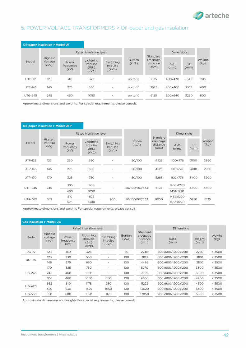
49Instrument transformers | High voltage 49
Oil-paper insulation > Model UT
ModelHighest Voltage
(kV)
Rated insulation level
Burden (kVA)
Standard creepage distance
(mm)
Dimensions
Weight(kg)Power
frequency (kV)
Lightning impulse
(BIL) (kVp)
Switching impulse (kVp)
AxB(mm)
H(mm)
UTE-72 72.5 140 325 - up to 10 1825 400x430 1645 285
UTE-145 145 275 650 - up to 10 3625 400x400 2105 400
UTG-245 245 460 1050 - up to 10 6125 500x640 3260 800
Approximate dimensions and weights. For special requirements, please consult.
5. POWER VOLTAGE TRANSFORMERS > Oil-paper and gas insulation
Oil-paper insulation > Model UTP
ModelHighest Voltage
(kV)
Rated insulation level
Burden (kVA)
Standard creepage distance
(mm)
Dimensions
Weight(kg)Power
frequency (kV)
Lightning impulse
(BIL) (kVp)
Switching impulse (kVp)
AxB(mm)
H(mm)
UTP-123 123 230 550 - 50/100 4525 1100x776 3100 2950
UTP-145 145 275 650 - 50/100 4525 1101x776 3100 2950
UTP-170 170 325 750 - 50/100 5285 1102x776 3400 3200
UTP-245 245395 900
- 50/100/167/333 61251450x1220
4590 4500460 1050 1451x1220
UTP-362 362510 1175
950 50/100/167/333 90501452x1220
5270 5135575 1300 1453x1220
Approximate dimensions and weights For special requirements, please consult
Gas insulation > Model UG
ModelHighest voltage
(kV)
Rated insulation level
Burden(kVA)
Standard creepage distance
(mm)
Dimensions
Weight(kg)
Power frequency
(kV)
Lightning impulse
(BIL)(kVp)
Switching Impulse (kVp)
Base(mm)
Height(mm)
UG-72 72.5 140 325 - 50 2248 600x600/1200x1200 2250 < 3500
UG-145123 230 550 - 100 3813 600x600/1200x1200 3100 < 3500
145 275 650 - 100 4495 600x600/1200x1200 3100 < 3500
UG-245
170 325 750 - 100 5270 600x600/1200x1200 3300 < 3500
245 460 1050 - 100 7595 600x600/1200x1200 3800 < 3500
300 460 1050 850 100 9300 600x600/1200x1200 4200 < 3500
UG-420362 510 1175 950 100 11222 900x900/1200x1200 4600 < 3500
420 630 1425 1050 100 13020 900x900/1200x1200 5300 < 3500
UG-550 550 680 1550 1175 100 17050 900x900/1200x1200 5800 < 3500
Approximate dimensions and weights For special requirements, please consult
50 Instrument transformers | High voltage
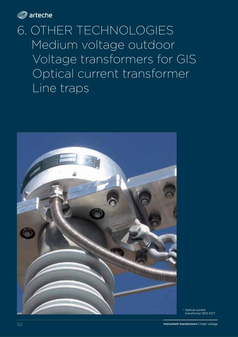
6. OTHER TECHNOLOGIES Medium voltage outdoor Voltage transformers for GIS Optical current transformer Line traps
› Optical current transformer SDO OCT.
51Instrument transformers | High voltage 51
6. OTHER TECHNOLOGIES
Medium voltage outdoor instrument transformers.
Voltage transformers for GIS.
Optical current transformer. Digital measurement.
Line traps.
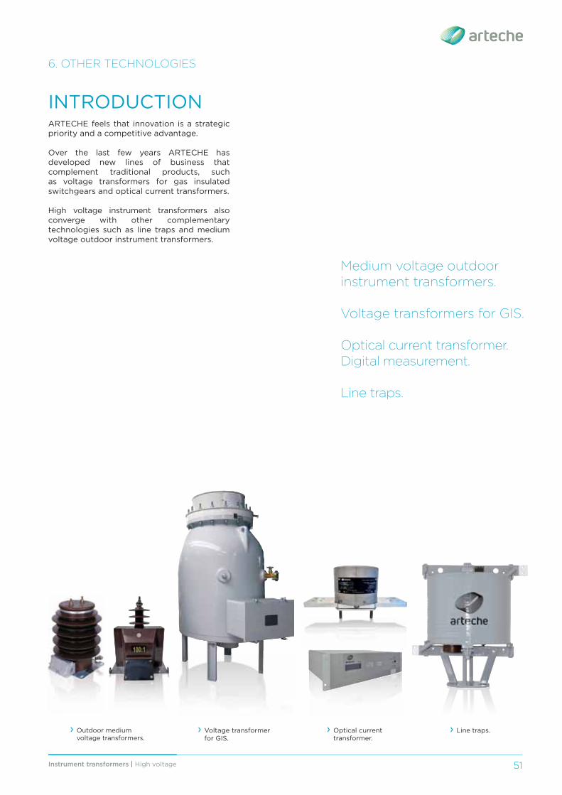
ARTECHE feels that innovation is a strategic priority and a competitive advantage.
Over the last few years ARTECHE has developed new lines of business that complement traditional products, such as voltage transformers for gas insulated switchgears and optical current transformers.
High voltage instrument transformers also converge with other complementary technologies such as line traps and medium voltage outdoor instrument transformers.
INTRODUCTION
› Line traps. › Voltage transformer for GIS.
› Outdoor medium voltage transformers.
› Optical current transformer.
Instrument transformers | High voltage52
6. OTHER TECHNOLOGIES
MEDIUM VOLTAGE OUTDOOR INSTRUMENT TRANSFORMERS
CURRENT TRANSFORMERS Current transformers:models CX/CR/CEup to 72.5 kV;model CPE up to 36 kV.
Inductive voltagetransformers:models UR/UT up to 72.5 kV;model VR up to 52 kV;models UJ/ VJ/UZK/VZKup to 36 kV.
Combined transformer:model KM up to 36 kV.
Dry transformers with external cycloaliphatic resin insulation (CR, CE, CPE), or with external porcelain insulation (CX).
Dry transformers with external cycloaliphatic resin insulation (UR, VR), or with external silicone rubber insulation (UJ, VJ).
Oil-paper transformers with external porcelain or silicon rubber insulator (UZK, VZK).
INDUCTIVE VOLTAGE TRANSFORMERS
A current transformer and a voltage transformer in the same resin body surrounded by cycloaliphatic resin (KM).
COMBINED TRANSFORMERS
For more information, refer to the catalog: Medium Voltage Outdoor Instrument Transformers.
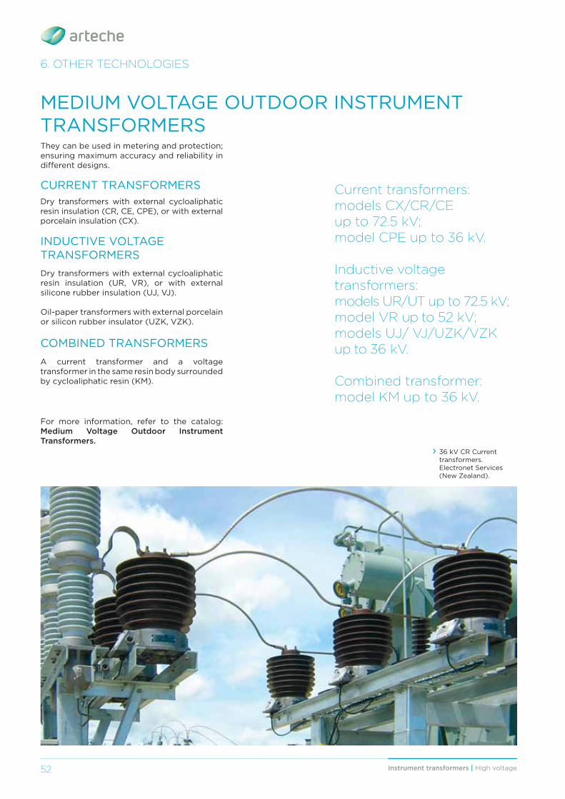
They can be used in metering and protection; ensuring maximum accuracy and reliability in diff erent designs.
› 36 kV CR Current transformers. Electronet Services (New Zealand).
53Instrument transformers | High voltage 53
6. OTHER TECHNOLOGIES
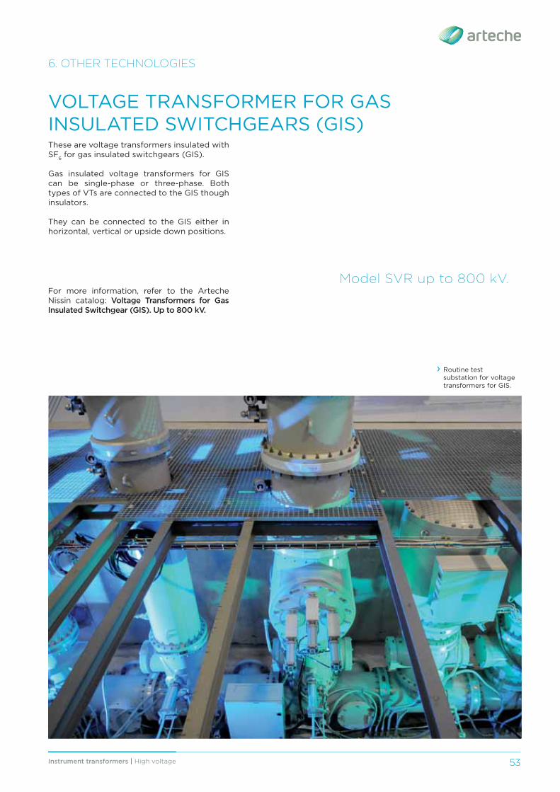
VOLTAGE TRANSFORMER FOR GAS INSULATED SWITCHGEARS (GIS)These are voltage transformers insulated with SF6 for gas insulated switchgears (GIS).
Gas insulated voltage transformers for GIS can be single-phase or three-phase. Both types of VTs are connected to the GIS though insulators.
They can be connected to the GIS either in horizontal, vertical or upside down positions.
Model SVR up to 800 kV.
› Routine test substation for voltage transformers for GIS.
For more information, refer to the Arteche Nissin catalog: Voltage Transformers for Gas Insulated Switchgear (GIS). Up to 800 kV.
Instrument transformers | High voltage54
6. OTHER TECHNOLOGIES
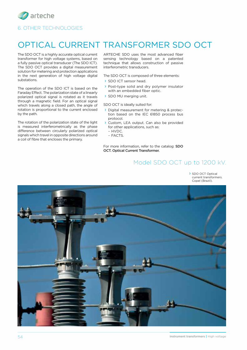
OPTICAL CURRENT TRANSFORMER SDO OCTThe SDO OCT is a highly accurate optical current transformer for high voltage systems, based on a fully passive optical transducer (The SDO ICT). The SDO OCT provides a digital measurement solution for metering and protection applications in the next generation of high voltage digital substations.
The operation of the SDO ICT is based on the Faraday Eff ect. The polarization state of a linearly polarized optical signal is rotated as it travels through a magnetic fi eld. For an optical signal which travels along a closed path, the angle of rotation is proportional to the current enclosed by the path.
The rotation of the polarization state of the light is measured interferometrically as the phase diff erence between circularly polarized optical signals which travel in opposite directions around a coil of fi bre that encloses the primary.
Model SDO OCT up to 1200 kV.
› SDO OCT Optical current transformers. Copel (Brazil).
For more information, refer to the catalog: SDO OCT. Optical Current Transformer.
ARTECHE SDO uses the most advanced fi ber sensing technology based on a patented technique that allows construction of passive interferometric transducers.
The SDO OCT is composed of three elements: › SDO ICT sensor head. › Post-type solid and dry polymer insulator with an embedded fi ber optic.
› SDO MU merging unit.
SDO OCT is ideally suited for: › Digital measurement for metering & protec-tion based on the IEC 61850 process bus protocol.
› Custom, LEA output. Can also be provided for other applications, such as:- HVDC.- FACTS.
55Instrument transformers | High voltage 55
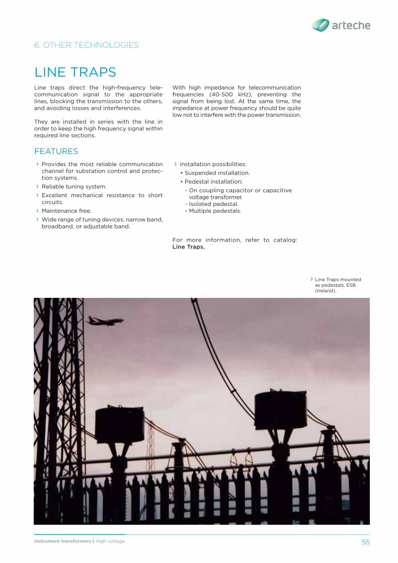
LINE TRAPS
FEATURES
Line traps direct the high-frequency tele-communication signal to the appropriate lines, blocking the transmission to the others, and avoiding losses and interferences.
They are installed in series with the line in order to keep the high frequency signal within required line sections.
› Provides the most reliable communication channel for substation control and protec-tion systems.
› Reliable tuning system. › Excellent mechanical resistance to short circuits.
› Maintenance free. › Wide range of tuning devices: narrow band, broadband, or adjustable band.
With high impedance for telecommunication frequencies (40-500 kHz), preventing the signal from being lost. At the same time, the impedance at power frequency should be quite low not to interfere with the power transmission.
6. OTHER TECHNOLOGIES
› Installation possibilities: • Suspended installation. • Pedestal installation:
- On coupling capacitor or capacitive voltage transformer.
- Isolated pedestal.- Multiple pedestals.
› Line Traps mounted as pedestals. ESB (Ireland).
For more information, refer to catalog: Line Traps.
56 Instrument transformers | High voltage
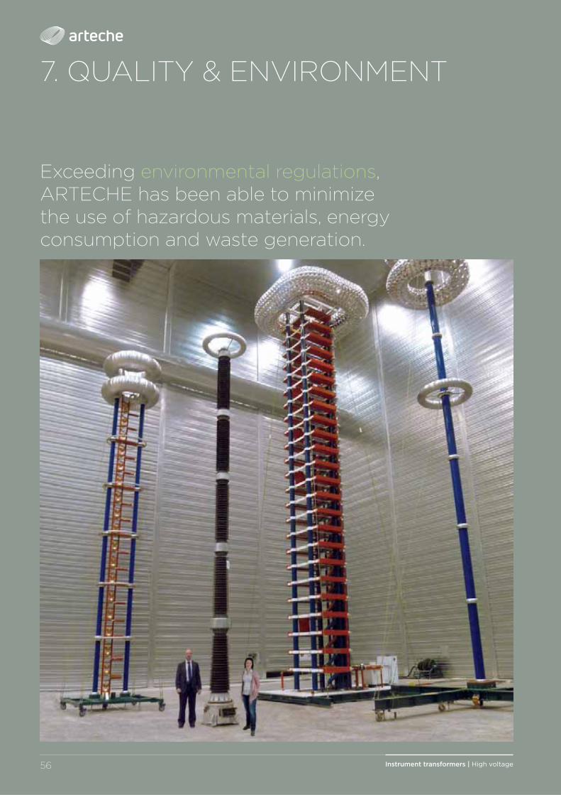
7. QUALITY & ENVIRONMENT
Exceeding environmental regulations, ARTECHE has been able to minimize the use of hazardous materials, energy consumption and waste generation.
57Instrument transformers | High voltage
QUALITY & ENVIRONMENT
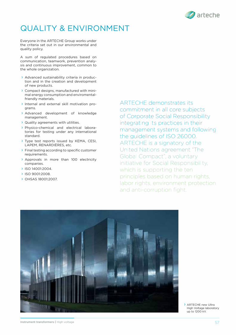
› ARTECHE new Ultra High Voltage laboratory up to 1200 kV.
ARTECHE demonstrates its commitment in all core subjects of Corporate Social Responsibility iinntteeggrraattiinngg iittss pprraaccttiicceess iinn tthheeiirr mmaannaagggeemmeenntt ssyyysstteemmss aanndd ffoolllloowwiinnggg ttthhhee gguuiiidddeellliiinneess oofff IIISSSOOO 222666000000000.. AARRTTEECCHHEE iiss aa ssiigggnnaattoorryyy ooff tthhee UUUUnnnniiiitttteeeedddd NNNNaaaattttiiiioooonnnnssss aaaaggggrrrreeeeeeeemmmmeeeennnntttt “TTTThhhheeee GGGllloobbbaalll CCCoommppaaccttt””, aa vvoollluunntttaarryy iiinniiitttiiiaatttiiivvee fffoorr SSSoocciiiaalll RRReessppoonnssiiibbbiiillliiitttyy,, wwhhhiiicchhh iiiss ssuuppppoorrtttiiinngg ttthhhee ttteenn principles based on human rights, labor rights, environment protection and anti-corruption fi ght.
Everyone in the ARTECHE Group works under the criteria set out in our environmental and quality policy.
A sum of regulated procedures based on communication, teamwork, prevention analy-sis and continuous improvement, common to the whole organization.
› Advanced sustainability criteria in produc-tion and in the creation and development of new products.
› Compact designs, manufactured with mini-mal energy consumption and enviromental-friendly materials.
› Internal and external skill motivation pro-grams.
› Advanced development of knowledge management.
› Quality agreements with utilities. › Physico-chemical and electrical labora-tories for testing under any international standard.
› Type test reports issued by KEMA, CESI, LAPEM, RENARDIÈRES, etc.
› Final testing according to specifi c customer requirements.
› Approvals in more than 100 electricity companies.
› ISO 14001:2004. › ISO 9001:2008. › OHSAS 18001:2007.
58 Instrument transformers | High voltage
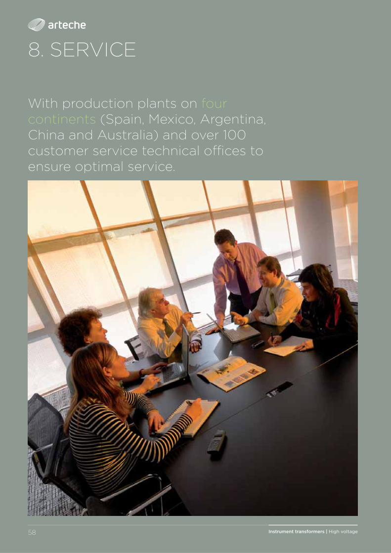
8. SERVICE
With production plants on four continents (Spain, Mexico, Argentina, China and Australia) and over 100 customer service technical offi ces to ensure optimal service.
59Instrument transformers | High voltage
ARTECHE has the techhnolloggyy andd cappaciitiies oofff iiinnsstttrruummeennttt tttrraannssfffoorrmmeerrss.. TTThhhuuss wwee pprroovviiidddee ttthhhee bbbeessttt ssssoooolllluuuuttttiiiioooonnnn aaaavvvvaaaaiiiillllaaaabbbblllleeee oooonnnn tttthhhheeee mmmaaarrrkkkeeettt..
› ARTECHE's service is based on a close relationship with the customers, refl ected in the integrated post-sale assistance plan and structured client opinion system.
› In addition to ensuring rapid response, ARTECHE developed a continuous service improvement plan, which sustains an extensive training program with courses, publications, conferences, etc.
› ARTECHE’s focus on service, with a broad experience leading us to be an active participant in the electrical organizations such as: IEC, IEEE, CIGRE, CIRED, ASINEL, etc.
› ARTECHE has production facilities on four continents (North America, South America, Europe, Asia and Australia) and more than 100 technical/commercial offi ces. Thus ARTECHE provides eff ective responses to the requirements of any customer and situation, based on the global knowledge acquired.
SERVICE
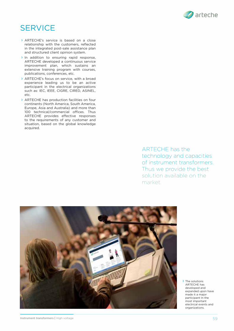
› The solutions ARTECHE has developed and expanded upon have made it a major participant In the most important electrical events and organizations.

www.arteche.com ©ARTECHE
Moving together
ARTECHE_CT_trfHV_ENVersion: B0