HIGH VOL TAGE TESTING OF TRANSFORMER BY HARI SHANKAR SINGH
30
Seminar guide Seminar coordinator Ms. Aanchal Baranwal Mr. Alok pandey (Assistant professor) (Assistant professor) Department of Electrical Department of Electrical Engineering Engineering A Seminar on High voltage testing of Electrical Transformer PRESENTED BY Hari Shankar Singh:-1308220902
-
Upload
shankar-singh -
Category
Documents
-
view
119 -
download
4
Transcript of HIGH VOL TAGE TESTING OF TRANSFORMER BY HARI SHANKAR SINGH

Seminar guide Seminar coordinator
Ms. Aanchal Baranwal Mr. Alok pandey (Assistant professor) (Assistant professor)
Department of Electrical Department of Electrical
Engineering Engineering
A
Seminar on
High voltage testing of Electrical Transformer
PRESENTED BY
Hari Shankar Singh:-1308220902

CONTENTS
Introduction of transformer and HV transformer
Types of testing of transformer and explain with
detail
Advantages of HV testing of transformer
Disadvantages of HV testing of transformer
Conclusion
References

What is Transformer ?
• Transformer is an electrostatic device which
transfer electrical energy one circuit to another
circuit by magnetic flux without change of
frequency . Transformer has based on principle
of electromagnetic induction(EMI).
• Formula used as measured a value,
Vs / V p = Ns / N p = I p / Is

HIGH VOLTAGE TRANSFORMER
• High voltage transformers convert voltages from
one level or phase configuration to another,
usually from higher to lower.
• They can include features for electrical isolation,
power distribution, and control and
instrumentation applications.
• High voltage transformers usually depend on
the principle of magnetic induction between
coils to convert voltage and current levels .

TYPES OF HV TESTING OF ELECTRICAL TRANSFORMER
1. Partial discharge test
2. Impulse transformer test
3. Transformer turns ratio test
4. Insulation resistance test
5. Routine test
6. Temperature rise of oil testing of transformer

PARTIAL DISCHARGE TEST
• Partial discharge is a small localised dielectric
breakdown of an electrical insulation system
under high voltage stress.
• Each discrete partial discharge is the result of an
electrical breakdown of an air pocket within the
insulation.
• These discharges erode insulation and
eventually result in insulation failure.

• Acoustic techniques are used by manufacturers
to locate discharges that occur during HV testing
factory.
• PD occurs if the electric field strength applied to
a dielectric exceeds the dielectric withstand
strength of an insulation system locally.
• This may be caused by either increased field
strengths , e.g. due to design problems, sharp
edges on electrodes, small clearances , ageing ,
manufacture defect , insulation failure , damage
etc.

PDT TEST CIRCUIT DIAGRAM
Fig.1

CAUSES OF FAILURE IN PDT
Fig.2

FAILURE LOCATION OF PDT
Fig.3

FUTURE APPLIANCES FROM PDT
• Cables and Power transformers and bushings.
• Switchgear.
• Motors and generators
• Conclusion PDT testing prevents failure,
1. Off-line testing is a critical pre-commissioning
check.
2. On- line testing is an extremely powerful non-
instructive condition monitoring tool.

IMPULSE TRANSFORMER TEST
• This test is made to prove that the transformer
insulation will withstand voltage surges which
may be caused by lightning or switching.
• This includes insulation to ground, insulation
between turns and windings, and the flashover
value of the associated bushings.
• A high-voltage wave of standard values, and
approximating a lightning surge, is imposed on
the unit to be tested.
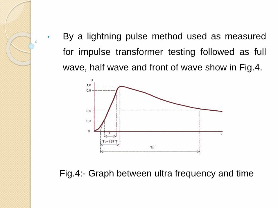
• By a lightning pulse method used as measured
for impulse transformer testing followed as full
wave, half wave and front of wave show in Fig.4.
Fig.4:- Graph between ultra frequency and time

CONNECTION DIAGRAM OF IMPULSE TRANSFORMER
TEST
Fig.5:-Connection of Impulse transformer test

TRANSFORMER TURN’S RATIO TEST
• The Transformer Turns Ratio test is used to
make sure that the Turns Ratio between the
winding of the transformer is correct.
• With this information, you can decide what the
output voltage of the transformer will be. The
ratio is calculated under no-load conditions using
formula given below,
V pri /V sec = Z pri/ Z sec = (N pri /N sec )2

INSULATION RESISTANCE TEST
(IR VALUE TEST)
• Insulation ages and deteriorates because of
moisture, dust and electrostatic stress. Insulation
should be monitored continually to avoid sudden
failure of the equipment.
• An insulation resistance test detects insulation
quality within the transformer.
• The conductive impurities or mechanical flows in
the dielectric can be analysis based on this test.

CONNECTION OF IR VALUE TESTING DIAGRAM
Fig.6:- IR Value testing connection diagram

• Normally, MEGGERS have a test voltage of
500V , 2500V , or 5000V .
• IR between HV and LV as well as windings to
earth.
• Minimum IR value for Tap changer is 1000 ohm
per volt service voltage

FACTORS AFFECTING ON IR VALUE OF TRANSFORMER
• The IR value of transformers are influenced by
Surface condition of the terminal bushing.
• Quality of oil.
• Quality of winding insulation.
• Temperature of oil.
• Duration of application and value of test voltage.

IR VALUE TESTING FORMULAS
• 1 Phase Transformer
IR Value (MΩ) = C X E / (√KVA)
• 3 Phase Transformer (Star)
IR Value (MΩ) = C X E (P-n) / (√KVA)
• 3 Phase Transformer(Delta)
IR Value (MΩ) = C X E (P-P) / (√KVA)
Where C= 1.5 for Oil filled T/C with Oil Tank,
30 for Oil filled T/C without Oil Tank or Dry Type T/C.

ROUTINE TEST FOR TRANSFORMER
A Routine test of transformer is mainly for confirming
operational performance of individual unit in a
production lot. Routine tests are carried out on every
unit manufactured.
All transformers are subjected to the following
Routine tests:
• Insulation resistance Test.
• Winding resistance Test.
• Turns Ratio / Voltage ratio Test

• Polarity / Vector group Test
• Open circuit and short circuit Test.
• Continuity Test.
• High Voltage Test.
• Partial discharge Test.
• Separate source AC voltage.
• Induced overvoltage.
• Lightning impulse Tests.
• On -load tap changers Test.
TEMPERATURE OIL TESTING OF TRANSFORMER
• Temperature rise test of oil of Transformer is
included in type test of transformer.
• In this test we check whether the temperature
rising limit of transformer winding and oil as per
specification or not.
• Faults detects at above 75˚C by the help of
Buchholz relay and work as ALARM and TRIP
circuit.

BUCHHOLZ RELAY, EXPAIL BY THE THIS
VIDEO

ADVANTAGES OF HV TESTING TRANSFORMER
• Pure conductivity by IR Value test.
• Controlling of HV surges by Impulse test.
• Removing of discrete waveform by the help of
Partial Discharge test.
• Terminals has used connected correctly by
Transformer Turn’s Ratio test.
• Units measured a correctly and manufacturing
defect check by Routine test.
•

DISADVANTAGES OF HV TESTING OF TRANSFORMER
• After failure, transformer is removed and
replaced with new/repaired one without removing
the cause of failure which results in immediate or
short time failure.
• Insufficient Oil level.
• Faulty operation of tap changer switch.
• Lack of installation checks.
• Prolonged Over loading.

CONCLUSION
• Knowledge of the construction of high voltage test
transformers, their design and use in high voltage
testing system gives the solution of the most
adjustment transformer in respect of parameters
and prices.
• HV testing are main advantages of safety ,
higher efficiency , lower cost ,savings of energy ,
avoiding of failures ,trouble shooting for failure
detection , accurate detection , quality assurance.

REFERENCES
• R.S. Jha, “High Voltage Engineering”, Dhanpat
Rai & Sons, Second Edition in 1996.
• C. L. Wadhwa, “High Voltage Engineering”, Wiley
Eastern Ltd. Third Edition in 2012.
• E.Kuffel and W.S. Zaengl, “High Voltage
Engineering” , Pergamon Press, First Edition
in1984.


444444444


![INDEX [clists.nic.in]clists.nic.in/ddir/PDFCauselists/patna/2016/Apr/...Sri Hari Shankar Singh, A.R. Criminal Disposal Section Sri Akhilesh Kumar Singh, A.R. Cr. Appeal Sri Rajesh](https://static.fdocuments.in/doc/165x107/5f1b9acde142b31d530c36e2/index-sri-hari-shankar-singh-ar-criminal-disposal-section-sri-akhilesh.jpg)