
HIGH VISCOSITY JETTING SYSTEM FOR 3D REACTIVE INKJET …
9
HIGH VISCOSITY JETTING SYSTEM FOR 3D REACTIVE INKJET PRINTING H. Yang, Y. He, C. Tuck, R. Wildman, I. Ashcroft, P. Dickens, R. Hague Additive Manufacturing and 3D printing group, University of Nottingham, NG7 2RD, UK Abstract High viscosity ink is a potential solution for the improvement of current 3D ink jetting technology. In this study, experiments are carried out to study a series of inks with differing viscosities jetted with PicoDot TM jet valves under different process parameters of temperature and pressure. Results show that a wide range of ink materials from low viscosity (water like materials) to very high viscosity (thixotropic materials) can be jetted with the piezoelectric actuated jet valves without the need of solvents and surfactants. The jetting volume can be controlled under certain conditions between 2nl and 15nl. The jetting performances for low, medium and high viscosity inks have been recorded by high-speed video photography. Introduction In the last two decades ink-jet printing technology has seen enormous development as a precision micro dispensing tool [1-3]. Traditionally inkjet printing has been mostly applied in the fabrication of 2D patterns or structures due to the requirement of low viscosity of inks. An amount of solvent is needed to dilute the printed materials to facilitate printing while the solvent also needs to evaporate quickly after printing. If not carefully controlled, the solvent can induce problems such as ink clotting or air pollution, which usually demands additional complex and corrective cleaning processes. To circumvent such a problem, in some applications, instead of using a solvent, low viscosity molecules are chosen as the ink for inkjet printing directly. After printing, the droplet will quickly solidify through reaction under the initiation of a catalyst, heat or high energy radiation such as ultra-violet (UV) light. Such printing is known as reactive inkjet printing. With no solvent or very few solvents used in the printing process, problems identified in the traditional inkjet printing can be effectively avoided. Because of 100% solidification, the reactive inkjet printing is also promising for 3D printing. Using UV curable polymers, 3D inkjet printers have been successfully developed and commercialized such as those sold by Objet [4]. The majority of UV curable polymers used for 3D printing are low molecular weight acrylates and the mechanical properties are therefore limited in their industrial applications. To prompt new applications for Additive Manufacturing (AM) and 3D printing, the development of new reactive printing materials and new printing processes are significant issues for exploration in the development of reactive inkjet printing. Researchers have been working on different reactive monomers, oligomers or prepolymers, like UV curable epoxy [5], caprolactam [6, 7], two components polyurethane [8], anionic and cationic polyelectrolytes [9] and hydrogels [10]. Some of the traditional polymerization and processing technologies can be applied into RIJP with the reaction scale being reduced from the macro to the micro, such as crosslinking or using a reactive prepolymer. An ink jetting 505
Transcript of HIGH VISCOSITY JETTING SYSTEM FOR 3D REACTIVE INKJET …
HIGH VISCOSITY JETTING SYSTEM FOR 3D REACTIVE INKJET PRINTING
H. Yang, Y. He, C. Tuck, R. Wildman, I. Ashcroft, P. Dickens, R. Hague
Additive Manufacturing and 3D printing group, University of Nottingham, NG7 2RD, UK
Abstract
High viscosity ink is a potential solution for the improvement of current 3D ink jetting technology. In this study, experiments are carried out to study a series of inks with differing viscosities jetted with PicoDotTM jet valves under different process parameters of temperature and pressure. Results show that a wide range of ink materials from low viscosity (water like materials) to very high viscosity (thixotropic materials) can be jetted with the piezoelectric actuated jet valves without the need of solvents and surfactants. The jetting volume can be controlled under certain conditions between 2nl and 15nl. The jetting performances for low, medium and high viscosity inks have been recorded by high-speed video photography.
Introduction In the last two decades ink-jet printing technology has seen enormous development as a precision micro dispensing tool [1-3]. Traditionally inkjet printing has been mostly applied in the fabrication of 2D patterns or structures due to the requirement of low viscosity of inks. An amount of solvent is needed to dilute the printed materials to facilitate printing while the solvent also needs to evaporate quickly after printing. If not carefully controlled, the solvent can induce problems such as ink clotting or air pollution, which usually demands additional complex and corrective cleaning processes. To circumvent such a problem, in some applications, instead of using a solvent, low viscosity molecules are chosen as the ink for inkjet printing directly. After printing, the droplet will quickly solidify through reaction under the initiation of a catalyst, heat or high energy radiation such as ultra-violet (UV) light. Such printing is known as reactive inkjet printing.
With no solvent or very few solvents used in the printing process, problems identified in the traditional inkjet printing can be effectively avoided. Because of 100% solidification, the reactive inkjet printing is also promising for 3D printing. Using UV curable polymers, 3D inkjet printers have been successfully developed and commercialized such as those sold by Objet [4]. The majority of UV curable polymers used for 3D printing are low molecular weight acrylates and the mechanical properties are therefore limited in their industrial applications.
To prompt new applications for Additive Manufacturing (AM) and 3D printing, the development of new reactive printing materials and new printing processes are significant issues for exploration in the development of reactive inkjet printing. Researchers have been working on different reactive monomers, oligomers or prepolymers, like UV curable epoxy [5], caprolactam [6, 7], two components polyurethane [8], anionic and cationic polyelectrolytes [9] and hydrogels [10]. Some of the traditional polymerization and processing technologies can be applied into RIJP with the reaction scale being reduced from the macro to the micro, such as crosslinking or using a reactive prepolymer. An ink jetting
505
system that can deal with wide range of ink viscosity one key to the success of such 3D printing.
Viscosities of inks for traditional inkjet system is normally in the range of about 1-
40cP. Rosen et al.[11] and Kiyama et al [12] have developed ultrasonic droplet generation systems which are able to print fluids up to 3000 cP of viscosity. However, those jetting systems haven’t been used in printing-based additive manufacturing process due to the complexity and inconsistency of high viscosity jetting. This research will use a piezoelectric actuated jetting system, PicoDotTM jet valves[13], to jet materials of a wide range of viscosity. This jetting system combines mechanical and pneumatic mechanisms so that a higher force can be applied to the jetting materials. With the piezoelectric actuator, a high jetting frequency can be achieved for a fast manufacturing speed. In this study, the jetting capability of this system is evaluated and the possibility of using this system in 3D reactive inkjet printing is investigated.
Materials and Methods Inkjet printing system
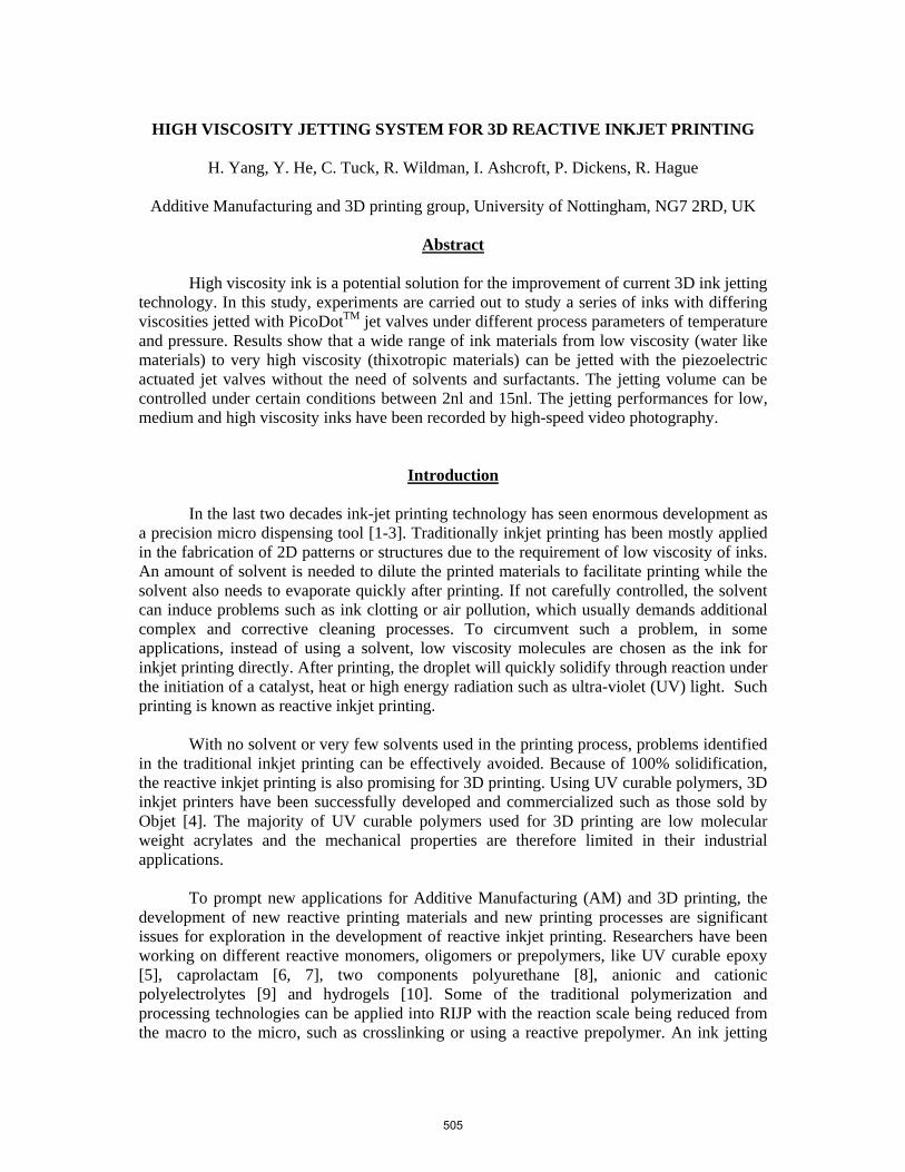
EFD PicoDotTM jet valves (Nordson EFD, UK) are used to jet inks under different temperatures and air pressures. Figure 1 shows the schematic drawing of the inside view of the jet valve and the assembled jetting system. Fluid fills the flow path and the jetting reservoir with a constant pressure from a syringe connected with compressed air through regulator, with the air pressure adjustable to up to 80psi. Driven by two piezoelectric actuators, a rod with a sealing ball made of wear-resistant ceramic at the lower end is lifted or lowered. The nozzle is closed by the sealing ball. When the sealing ball is lifted, fluid can flow through the valve. The extremely fast piezoelectric actuator helps to achieve a jetting frequency of up to 500 Hz. Depending on the fluid being using, the piezoelectric actuator can produce ink droplets of different size, with the smallest deposits being 2nl.
A controller is connected with the jetting valve to control the jetting time and jetting temperature. The high resolution PicoDot valve controller (0.01 ms) makes it possible to adjust the deposit size precisely. The temperature of the fluid path is also controlled via the PicoDot valve controller. The valves feature a heated fluid path with a maximum temperature of +100°C. The controller can also be connected to a computer so that the jetting process can be automatically controlled by the computer. A 3D stage used to enable 3D printing.
(a) (b)
Figure 1 Schematic of the PicoDotTM jetting valve (a) and the 3D jetting system (b)
506
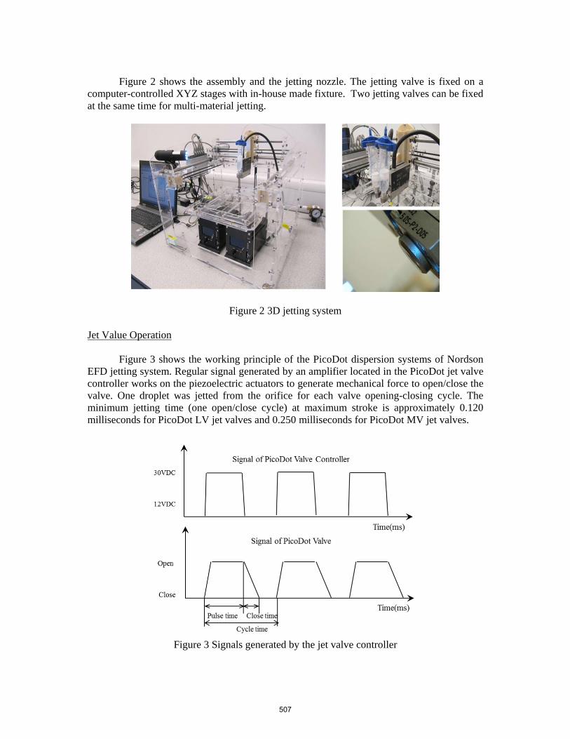
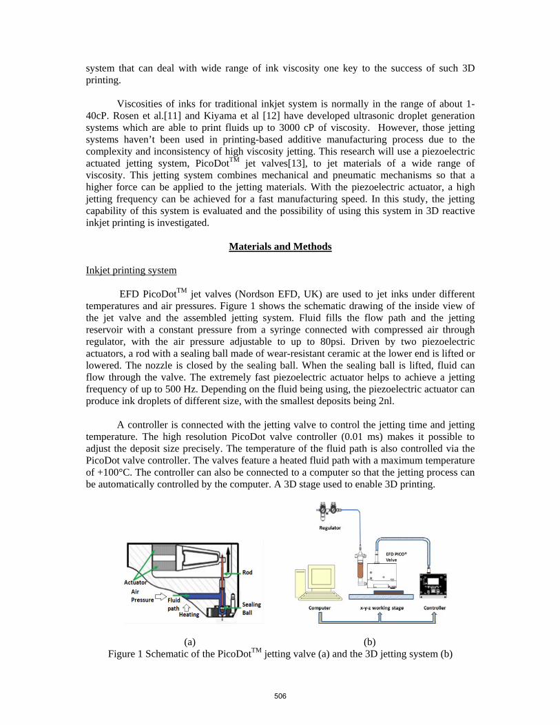
Figure 2 shows the assembly and the jetting nozzle. The jetting valve is fixed on a
computer-controlled XYZ stages with in-house made fixture. Two jetting valves can be fixed at the same time for multi-material jetting.
Figure 2 3D jetting system Jet Value Operation
Figure 3 shows the working principle of the PicoDot dispersion systems of Nordson EFD jetting system. Regular signal generated by an amplifier located in the PicoDot jet valve controller works on the piezoelectric actuators to generate mechanical force to open/close the valve. One droplet was jetted from the orifice for each valve opening-closing cycle. The minimum jetting time (one open/close cycle) at maximum stroke is approximately 0.120 milliseconds for PicoDot LV jet valves and 0.250 milliseconds for PicoDot MV jet valves.
Figure 3 Signals generated by the jet valve controller
507
For different materials, the droplet volume (V) can be controlled by optimizing the jetting parameters. The droplet volume is decided by two factors: the mechanical force and the pneumatic force (Equation 1). The material jetted due to the mechanical force is mainly decided by the structure of the jet valve, and the jetting rate (Qm) can be controlled by changing the close time (tclose). The jetting rate due to pneumatic force (Qp) can be calculated with Equation 2, which is decided by the power law constants n and K of a fluid, the pressure difference ΔP, and the nozzle configuration (diameter D and length L). Overall the jetting volume with the pneumatic force is the jetting rate (Qp) times the pulse time (tp).
ppclosem tQtQV (1)
n
P LK
PD
n
nDQ
13
413
4
32
(2)
Materials
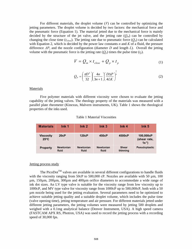
Five polymer materials with different viscosity were chosen to evaluate the jetting capability of the jetting valves. The rheology property of the materials was measured with a parallel plate rheometer (Kinexus, Malvern instruments, UK). Table 1 shows the rheological properties of the inks used.
Table 1 Material Viscosities
Jetting process study
The PicoDotTM valves are available in several different configurations to handle fluids with the viscosity ranging from 50cP to 500,000 cP. Nozzles are available with 50 µm, 100 µm, 150µm, 200µm, 300µm and 400µm orifice diameters to accommodate a wide range of ink dot sizes. An LV type valve is suitable for the viscosity range from low viscosity up to 1000cP, and MV type valve for viscosity range from 1000cP up to 500,000cP, both with a 50 µm nozzle being used for the jetting evaluation. Several parameters need to be optimized to achieve suitable jetting quality and a suitable droplet volume, which includes the pulse time (valve opening time), jetting temperature and air pressure. For different materials jetted under different jetting parameters, the jetting volumes were measured by jetting 500 droplets and weighed with a 0.1mg analytical balance (Denver Instrument, USA). A high speed camera (FASTCAM APX RS, Photron, USA) was used to record the jetting process with a recording speed of 30,000 fps.
508
Results
Material Characterization
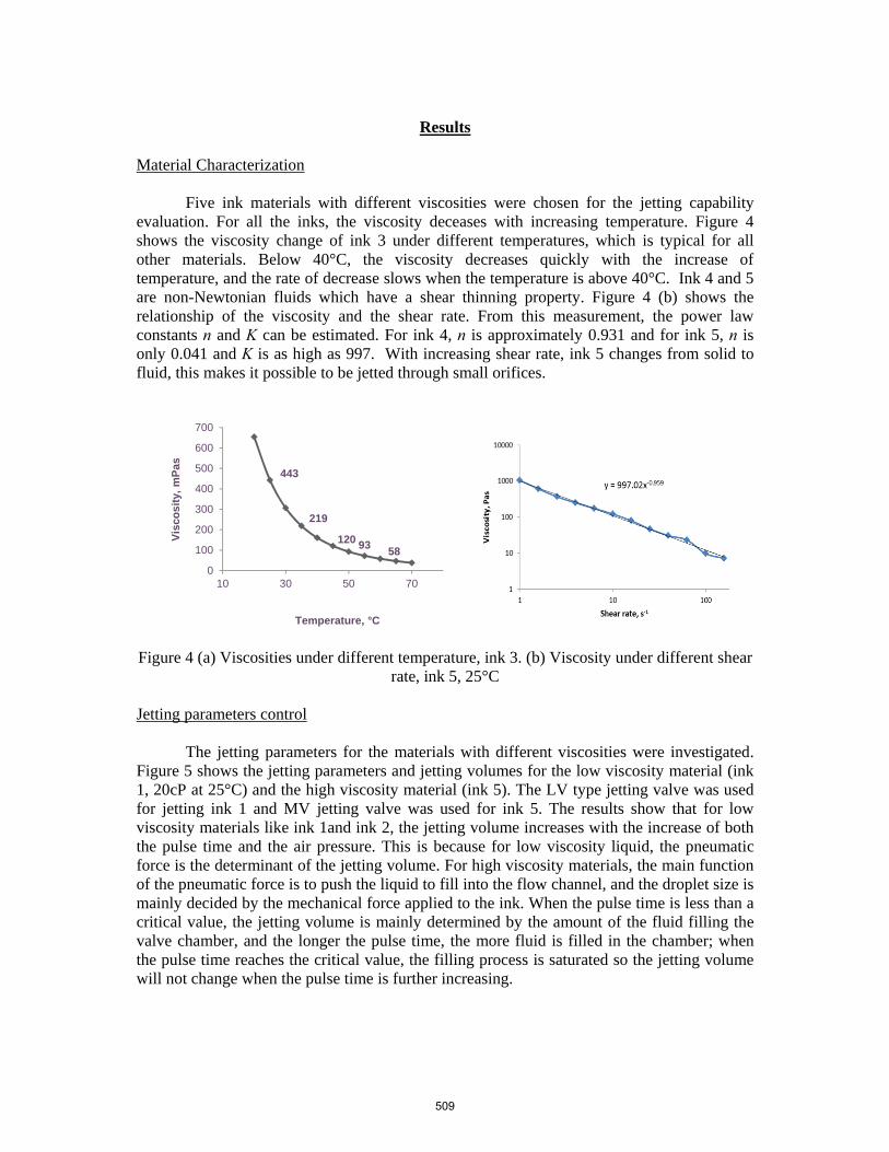
Five ink materials with different viscosities were chosen for the jetting capability evaluation. For all the inks, the viscosity deceases with increasing temperature. Figure 4 shows the viscosity change of ink 3 under different temperatures, which is typical for all other materials. Below 40°C, the viscosity decreases quickly with the increase of temperature, and the rate of decrease slows when the temperature is above 40°C. Ink 4 and 5 are non-Newtonian fluids which have a shear thinning property. Figure 4 (b) shows the relationship of the viscosity and the shear rate. From this measurement, the power law constants n and K can be estimated. For ink 4, n is approximately 0.931 and for ink 5, n is only 0.041 and K is as high as 997. With increasing shear rate, ink 5 changes from solid to fluid, this makes it possible to be jetted through small orifices.
Figure 4 (a) Viscosities under different temperature, ink 3. (b) Viscosity under different shear
rate, ink 5, 25°C
Jetting parameters control
The jetting parameters for the materials with different viscosities were investigated. Figure 5 shows the jetting parameters and jetting volumes for the low viscosity material (ink 1, 20cP at 25°C) and the high viscosity material (ink 5). The LV type jetting valve was used for jetting ink 1 and MV jetting valve was used for ink 5. The results show that for low viscosity materials like ink 1and ink 2, the jetting volume increases with the increase of both the pulse time and the air pressure. This is because for low viscosity liquid, the pneumatic force is the determinant of the jetting volume. For high viscosity materials, the main function of the pneumatic force is to push the liquid to fill into the flow channel, and the droplet size is mainly decided by the mechanical force applied to the ink. When the pulse time is less than a critical value, the jetting volume is mainly determined by the amount of the fluid filling the valve chamber, and the longer the pulse time, the more fluid is filled in the chamber; when the pulse time reaches the critical value, the filling process is saturated so the jetting volume will not change when the pulse time is further increasing.
443
219
120 9358
0
100
200
300
400
500
600
700
10 30 50 70
Vis
cos
ity,
mP
as
Temperature, °C
509
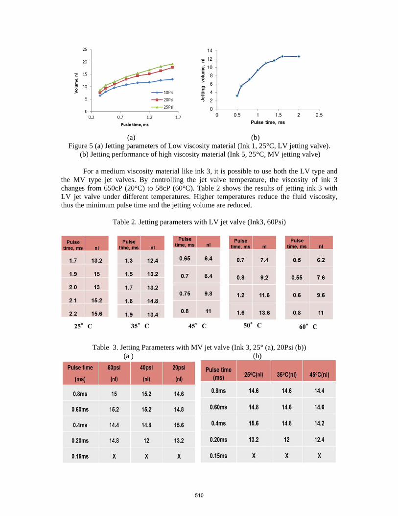
(a) (b)
Figure 5 (a) Jetting parameters of Low viscosity material (Ink 1, 25°C, LV jetting valve). (b) Jetting performance of high viscosity material (Ink 5, 25°C, MV jetting valve)
For a medium viscosity material like ink 3, it is possible to use both the LV type and
the MV type jet valves. By controlling the jet valve temperature, the viscosity of ink 3 changes from 650cP (20°C) to 58cP (60°C). Table 2 shows the results of jetting ink 3 with LV jet valve under different temperatures. Higher temperatures reduce the fluid viscosity, thus the minimum pulse time and the jetting volume are reduced.
Table 2. Jetting parameters with LV jet valve (Ink3, 60Psi)
Table 3. Jetting Parameters with MV jet valve (Ink 3, 25° (a), 20Psi (b)) (a ) (b)
510
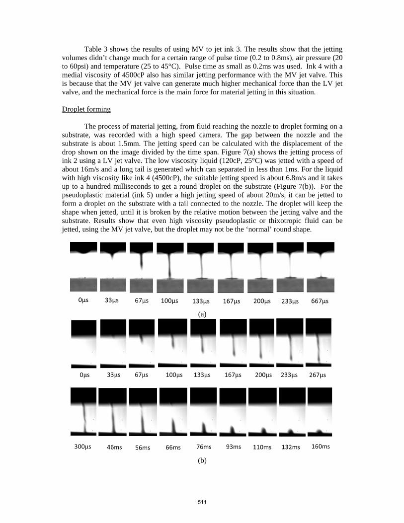
Table 3 shows the results of using MV to jet ink 3. The results show that the jetting volumes didn’t change much for a certain range of pulse time (0.2 to 0.8ms), air pressure (20 to 60psi) and temperature (25 to 45°C). Pulse time as small as 0.2ms was used. Ink 4 with a medial viscosity of 4500cP also has similar jetting performance with the MV jet valve. This is because that the MV jet valve can generate much higher mechanical force than the LV jet valve, and the mechanical force is the main force for material jetting in this situation.
Droplet forming The process of material jetting, from fluid reaching the nozzle to droplet forming on a substrate, was recorded with a high speed camera. The gap between the nozzle and the substrate is about 1.5mm. The jetting speed can be calculated with the displacement of the drop shown on the image divided by the time span. Figure 7(a) shows the jetting process of ink 2 using a LV jet valve. The low viscosity liquid (120cP, 25°C) was jetted with a speed of about 16m/s and a long tail is generated which can separated in less than 1ms. For the liquid with high viscosity like ink 4 (4500cP), the suitable jetting speed is about 6.8m/s and it takes up to a hundred milliseconds to get a round droplet on the substrate (Figure 7(b)). For the pseudoplastic material (ink 5) under a high jetting speed of about 20m/s, it can be jetted to form a droplet on the substrate with a tail connected to the nozzle. The droplet will keep the shape when jetted, until it is broken by the relative motion between the jetting valve and the substrate. Results show that even high viscosity pseudoplastic or thixotropic fluid can be jetted, using the MV jet valve, but the droplet may not be the ‘normal’ round shape.
(a)
(b)
511
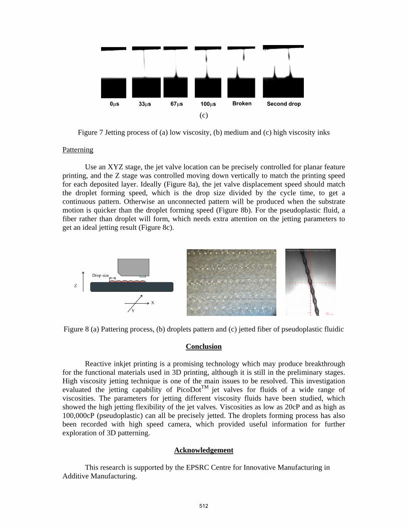
(c)
Figure 7 Jetting process of (a) low viscosity, (b) medium and (c) high viscosity inks
Patterning
Use an XYZ stage, the jet valve location can be precisely controlled for planar feature
printing, and the Z stage was controlled moving down vertically to match the printing speed for each deposited layer. Ideally (Figure 8a), the jet valve displacement speed should match the droplet forming speed, which is the drop size divided by the cycle time, to get a continuous pattern. Otherwise an unconnected pattern will be produced when the substrate motion is quicker than the droplet forming speed (Figure 8b). For the pseudoplastic fluid, a fiber rather than droplet will form, which needs extra attention on the jetting parameters to get an ideal jetting result (Figure 8c).
Figure 8 (a) Pattering process, (b) droplets pattern and (c) jetted fiber of pseudoplastic fluidic
Conclusion
Reactive inkjet printing is a promising technology which may produce breakthrough
for the functional materials used in 3D printing, although it is still in the preliminary stages. High viscosity jetting technique is one of the main issues to be resolved. This investigation evaluated the jetting capability of PicoDotTM jet valves for fluids of a wide range of viscosities. The parameters for jetting different viscosity fluids have been studied, which showed the high jetting flexibility of the jet valves. Viscosities as low as 20cP and as high as 100,000cP (pseudoplastic) can all be precisely jetted. The droplets forming process has also been recorded with high speed camera, which provided useful information for further exploration of 3D patterning.
Acknowledgement This research is supported by the EPSRC Centre for Innovative Manufacturing in Additive Manufacturing.
512
References
[1] M Singh, H M Haverinen, P Dhagat, et al., Inkjet Printing—Process and Its Applications, Adv. Mater. 2010, 22, 673–685.
[2] C J Ferris, K J Gilmore, S Beirne, Bio-ink for on-demand printing of living cells, Biomater. Sci., 2013, 1, 224.
[3] Takami Akagi, Tomoko Fujiwara, and Mitsuru Akashi, Rapid Fabrication of Polylactide Stereocomplex Using Layer-by-Layer Deposition by Inkjet Printing, Angew. Chem. Int. Ed. 2012, 51, 5493 –5496
[4] http://www.stratasys.com/
[5] T Wang. R. Patel, B Derby. Manufacture of 3-dimensional objects by reactive inkjet printing. Soft Matter 2008, 4(12), 2513-2518.
[6] K Khodabakhshi, M Gilbert, P Dickens, R Hague, Optimizing Conditions for
Anionic Polymerization of Caprolactam for Inkjetting, Advances in Polymer Technology, 2010, 00(0), 1–11
[7] K Khodabakhshi, M Gilbert, P Dickens, R Hague, S Fathi, New polymerization-mixture formulation for jetting: An approach toproduction of polyamide 6 parts, Tenth Annual International Solid Freeform Fabrication Symposium, 2009
[8] P Krober, J T Delaney, J Perelaer et al. . "Reactive inkjet printing of polyurethanes." Journal of Materials Chemistry 2009, 19(29): 5234-5238.
[9] S Limem, D McCallum, G G Wallace, et al. Inkjet printing of self-assembling polyelectrolyte hydrogels, Soft Matter, 2011, 7, 3818
[10] R Zhang, A Liberski, F Khan, J Diaz-Mochon and M Bradley , Inkjet fabrication of hydrogel microarrays using in situ nanolitre-scale polymerisationw, Chem. Commun., 2008, 1317–1319
[11]http://utwired.engr.utexas.edu/lff/symposium/proceedingsArchive/pubs/Manuscripts/2008/2008-22-Rosen.pdf
[12] Y. Kiyama, Y. Tominaga, T. Kanda, Micro Droplet generation using micropore plates oscillated by ultrasonic torsional transducers. IEEE, 2011, 88-93
[13] http://www.nordson.com/
513