High Velocity Impact Behaviour of Layered Steel Fibre ...
28
Copyright © 2014 Tech Science Press CMC, vol.42, no.1, pp.75-102, 2014 High Velocity Impact Behaviour of Layered Steel Fibre Reinforced Cementitious Composite (SFRCC) Panels Amar Prakash 1 , Srinivasan, S. M. 2 and Rama Mohan Rao, A. 3 Abstract: Behaviour of layered steel fibre reinforced cementitious composite (SFRCC) panels is studied under high velocity impact of short projectiles. The panels consist of slurry infiltrated fibre concrete (SIFCON) layers in external faces and an intermediate (core) layer of latex modified concrete (LMC) and steel wire mesh embedded in cement sand slurry. In order to minimize acoustic impedance mismatch at the interfaces, judiciously selected materials are provided in the layers with appropriate lay-up sequences. For relative evaluation of high velocity impact performances of these panels’, impact experiments are conducted in controlled en- vironment. Two most commonly used types of short projectiles having calibre di- ameter of 5.56 mm and 7.62 mm are used in this study. Various important response parameters like depth of penetration (DOP), crater size, spalling, and cracking in the panels are considered for the performance evaluation. This paper presents the results of experimental study conducted on SFRCC panels. Considering the results obtained from experimental study, relative assessment of impact performances of SFRCC panels is carried out with respect to the materials of core layer. Influence of steel fibre volume on impact performance of the panels is also investigated and expressions are proposed based on regression analysis. In order to determine the residual impact resistance of the SFRCC panel after first hit, the same panel was impacted consecutively two to three times, generally within the damage zone of the first hit. Promising potential to resist high velocity impact is exhibited by the SFRCC panels. The structural integrity of the SFRCC panels is found intact even under multiple hits. Keywords: Fibres, Layered structures, Delamination, Impact behaviour, Lay-up. 1 CSIR-Structural Engineering Research Centre, Chennai-600113, India. 2 Department of Applied Mechanics, IIT Madras, Chennai-600036, India. 3 CSIR-Structural Engineering Research Centre, Chennai-600113, India.
Transcript of High Velocity Impact Behaviour of Layered Steel Fibre ...

Copyright © 2014 Tech Science Press CMC, vol.42, no.1, pp.75-102, 2014
High Velocity Impact Behaviour of Layered Steel FibreReinforced Cementitious Composite (SFRCC) Panels
Amar Prakash1, Srinivasan, S. M.2 and Rama Mohan Rao, A.3
Abstract: Behaviour of layered steel fibre reinforced cementitious composite(SFRCC) panels is studied under high velocity impact of short projectiles. Thepanels consist of slurry infiltrated fibre concrete (SIFCON) layers in external facesand an intermediate (core) layer of latex modified concrete (LMC) and steel wiremesh embedded in cement sand slurry. In order to minimize acoustic impedancemismatch at the interfaces, judiciously selected materials are provided in the layerswith appropriate lay-up sequences. For relative evaluation of high velocity impactperformances of these panels’, impact experiments are conducted in controlled en-vironment. Two most commonly used types of short projectiles having calibre di-ameter of 5.56 mm and 7.62 mm are used in this study. Various important responseparameters like depth of penetration (DOP), crater size, spalling, and cracking inthe panels are considered for the performance evaluation. This paper presents theresults of experimental study conducted on SFRCC panels. Considering the resultsobtained from experimental study, relative assessment of impact performances ofSFRCC panels is carried out with respect to the materials of core layer. Influenceof steel fibre volume on impact performance of the panels is also investigated andexpressions are proposed based on regression analysis. In order to determine theresidual impact resistance of the SFRCC panel after first hit, the same panel wasimpacted consecutively two to three times, generally within the damage zone ofthe first hit. Promising potential to resist high velocity impact is exhibited by theSFRCC panels. The structural integrity of the SFRCC panels is found intact evenunder multiple hits.
Keywords: Fibres, Layered structures, Delamination, Impact behaviour, Lay-up.
1 CSIR-Structural Engineering Research Centre, Chennai-600113, India.2 Department of Applied Mechanics, IIT Madras, Chennai-600036, India.3 CSIR-Structural Engineering Research Centre, Chennai-600113, India.

76 Copyright © 2014 Tech Science Press CMC, vol.42, no.1, pp.75-102, 2014
1 Introduction
Construction of layered steel fibre reinforced cementitious composite (SFRCC)panel to resist high velocity impact of short projectile is a challenging task. Itrequires judicious selection of materials to be provided in each layer and, an ap-propriate lay-up sequence. Most important function of an impact resistant (or pro-tective) structure is to dissipate the kinetic energy of a particular projectile withoutundergoing fragmentation and perforation. It is also, equally important for suchstructures, to resist repeated hits within the vicinity of damaged zone of previoushits, without losing structural integrity.
Innovations in the field of development of construction materials have exhibited ex-cellent materials for impact resistance. Presently, research in this area has attractedgreat interest among researchers over the past few decades [Soe, Zhang, and Zhang(2013)]. Steel bar reinforced concrete has extensively been used in the constructionof protective structures over the years. Usually the RCC protective structures havebulky volume to resist high velocity impact of projectiles [Dancygier (1998); Tham(2006)]. In addition to this, steel bar reinforced concrete is brittle, weak locally intension and its shatter resistance is also very low. Hence, catastrophic failure oc-curs in RCC protective structures under high velocity impact of short projectiles[Maalej, Quek, Zhang (2005)].
Studies to overcome the brittleness of concrete by incorporating discrete fibres intoplain cementitious matrix are reported in literature [Naaman, Otter, Najm (1992)].Fibre reinforced concrete (FRC) consisting of discrete short fibre volume between1% and 3% mixed with concrete has shown substantial improvement in the engi-neering properties like; tensile strength, ductility, fracture toughness and resistanceto shatter, in comparison with RCC and plain concrete. In the fibre reinforced com-posite materials, both the fibre and matrix retains their original physical and chemi-cal identities. But, synergetically together they produce a combination of enhancedmechanical properties that cannot be achieved with either of the constituents actingalone [Kim and Mai (1998)]. During the impact, strong bond between fibre andmatrix prevents crack propagation by means of crack bridging. Depending uponthe steel fibre lengths varying from10 mm to 60 mm, their volumes vary between0.5% and 30% in fibre concrete [Shah and Ribakov (2011)]. It has been reportedthat sizes, shapes and volumes of fibres influence impact resistant properties of ce-mentitious composites. Therefore, a careful selection of fibres and their optimumcontent in concrete are essential factors for the efficient construction of impact re-sistant structures. Special fibre composites having high fibre volume between 3%and 20% named as slurry infiltrated fibre concrete (SIFCON) reported [Farnam,Moosavi, Shekarchi, Babanajad, Bagherzadeh (2010)] to show further improvedenergy absorption at high strain rates. Unlike FRC, short discrete fibres are pre-
High Velocity Impact Behaviour of Layered Steel Fibre 77
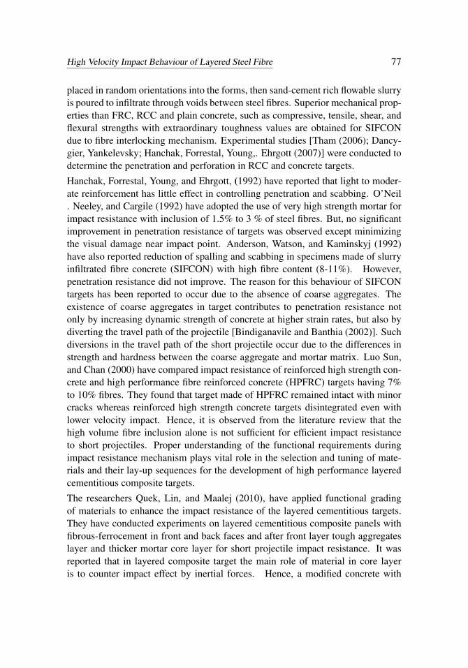
placed in random orientations into the forms, then sand-cement rich flowable slurryis poured to infiltrate through voids between steel fibres. Superior mechanical prop-erties than FRC, RCC and plain concrete, such as compressive, tensile, shear, andflexural strengths with extraordinary toughness values are obtained for SIFCONdue to fibre interlocking mechanism. Experimental studies [Tham (2006); Dancy-gier, Yankelevsky; Hanchak, Forrestal, Young,. Ehrgott (2007)] were conducted todetermine the penetration and perforation in RCC and concrete targets.
Hanchak, Forrestal, Young, and Ehrgott, (1992) have reported that light to moder-ate reinforcement has little effect in controlling penetration and scabbing. O’Neil. Neeley, and Cargile (1992) have adopted the use of very high strength mortar forimpact resistance with inclusion of 1.5% to 3 % of steel fibres. But, no significantimprovement in penetration resistance of targets was observed except minimizingthe visual damage near impact point. Anderson, Watson, and Kaminskyj (1992)have also reported reduction of spalling and scabbing in specimens made of slurryinfiltrated fibre concrete (SIFCON) with high fibre content (8-11%). However,penetration resistance did not improve. The reason for this behaviour of SIFCONtargets has been reported to occur due to the absence of coarse aggregates. Theexistence of coarse aggregates in target contributes to penetration resistance notonly by increasing dynamic strength of concrete at higher strain rates, but also bydiverting the travel path of the projectile [Bindiganavile and Banthia (2002)]. Suchdiversions in the travel path of the short projectile occur due to the differences instrength and hardness between the coarse aggregate and mortar matrix. Luo Sun,and Chan (2000) have compared impact resistance of reinforced high strength con-crete and high performance fibre reinforced concrete (HPFRC) targets having 7%to 10% fibres. They found that target made of HPFRC remained intact with minorcracks whereas reinforced high strength concrete targets disintegrated even withlower velocity impact. Hence, it is observed from the literature review that thehigh volume fibre inclusion alone is not sufficient for efficient impact resistanceto short projectiles. Proper understanding of the functional requirements duringimpact resistance mechanism plays vital role in the selection and tuning of mate-rials and their lay-up sequences for the development of high performance layeredcementitious composite targets.
The researchers Quek, Lin, and Maalej (2010), have applied functional gradingof materials to enhance the impact resistance of the layered cementitious targets.They have conducted experiments on layered cementitious composite panels withfibrous-ferrocement in front and back faces and after front layer tough aggregateslayer and thicker mortar core layer for short projectile impact resistance. It wasreported that in layered composite target the main role of material in core layeris to counter impact effect by inertial forces. Hence, a modified concrete with

78 Copyright © 2014 Tech Science Press CMC, vol.42, no.1, pp.75-102, 2014
adequate fracture toughness and presence of coarse aggregates is essential. Theyconcluded that an aggregate core layer helps in stopping short projectile impact.But severe cracking seems to occur in core layer under single hit of non-deformablesteel projectile leading vulnerability to further hits.
Kustermann, Karl-Christian, Christian, Manfred, Rupprecht (2009) have studiedvarious combinations of materials like marbles, glass and steel pebbles, ceramicand strong aggregates to provide tough layers on front and HSFRC rear face. It wasconcluded that the presence of hard and shatter resistant materials on the front faceprovided best results. However, it was observed that after single hit hard pebblesgot detached from front face of the panels leading to vulnerability of panels forrepeated hit.
Latex-modified concrete (LMC) is reported [Barluenga and Hernandez-Olivares(2004); Allan (1997)] to have better impact resistant properties in comparison withconventional mortar and concrete. Experimental investigation [Zai, Prasad, Gupta,Munirudrappa, and Muthumani, (2010)] reported better impact behaviour of latexmodified steel fibre reinforced concrete beams. Due to improved impact perfor-mance of LMC, it is considered as a suitable material as compared to aggregateand plain concrete, especially in core layer of layered composite panels. Hence inthe present study LMC is used in core layer to achieve reduction in fibre contentwithout affecting impact performance of layered SFRCC panels.
From the review of recent literature it is inferred that the construction of layeredcementitious composite panels requires both, judicious selection of material andtheir appropriate lay-up sequence. It is obvious that suitable materials, tuned tocater various material phase (i.e. Hydrodynamic, plastic and elastic) dependentstrength requirements, perform well during impact resistance. Hence, the conceptsreported in literature about the requirements of materials and high velocity impactdamage modes in layered cementitious composite target panels are duly considered.In this paper three types of layered composite panels are tested under normal impactof short projectiles having calibre 5.56 mm and 7.62mm.
The impact performances of the layered SFRCC panels with core layers namely,SIFCON (10% fiber by volume), LMC and wiremeshed reinforcement are rela-tively compared. Depending on the material used in face (front and back) and corelayers, the SFRCC panels are designated as SSS, SLS and SWS as shown in Fig-ure1. In order to determine residual impact resistance of the target panels after firsthit, similar panels are tested under two to three additional hits near the previoushits.
Influence of variation in steel fibre volumes (0, 2, 4, 6, 8, and 10%) on impact per-formance of 100 mm thick SSS type panels is also investigated. Empirical expres-

High Velocity Impact Behaviour of Layered Steel Fibre 79
sions are proposed for depth of penetrations, crater diameters and crater depths dueto impact of both the projectiles. The proposed empirical expressions for depth ofpenetration of 7.62 mm projectile in layered SFRCC panels are found to match wellwith the existing formulae [Bangash (1993)] for concrete targets given by ArmyCorps of Engineers (ACE) and National Defence Research Committee (NDRC).
Figure 1: Details of infill layer arrangements in SFRCC panels.
The main objective of this paper is to study the impact behaviour of layered SFRCCpanels through experimental investigations. Panels are prepared considering re-quirements like suitable energy absorbing materials, lay-up sequence, materialswith matching acoustic impedance for smooth stress wave propagation through thelayers. High velocity impact tests are conducted in reasonably controlled environ-ment where the munitions as well as ammunitions are kept common for all theimpact tests. Besides this the distance of shooting, angle of impact and boundaryconditions are kept same during impact tests. Impact performances are assessedrelatively based on both destructive and non-destructive tests. The results are com-pared with the existing empirical relations for depth of penetrations. The resultsof experimental investigations on layered SFRCC panels show excellent impactresistance even under multi-hit situations.
The present paper is organized mainly in four sections. Details of the experimen-tal study including mechanical properties of materials used in preparation of theSFRCC panels, impact test set up and procedure of impact tests are described in

80 Copyright © 2014 Tech Science Press CMC, vol.42, no.1, pp.75-102, 2014
section 2. The results of experimental investigations on layered SFRCC panels arediscussed in section 3. Conclusions drawn based on the experimental investigationsare provided in section 4. A brief explanation of the concepts behind the selectionof material and layering arrangement in the SFRCC panels used in the present studyis provided in appendix (A).
2 Experimental Study
An experimental study is conducted on layered SFRCC panels to understand thehigh velocity impact behaviour. In order to have a realistic assessment of impactperformances of the panels, in-service munitions (INSAS and AK-47 rifles) andammunitions (5.56 mm and 7.62 mm calibre projectiles) are used. The impact testsare conducted in reasonably controlled conditions. The distance of shooting pointis kept 25 m primarily from safety consideration, so that no fragment after spallingcan hit back the shooter and aiming becomes easier. Since far-off target distancemay cause drop in the muzzle velocity of the projectile, hence it is avoided. It isworth mentioning here that the in-service weapons and ammunitions, time of testsand boundary conditions, support stand etc. are not changed during impact testingof the panels.
The plan dimensions (300 x 300 mm) of 100 mm thick layered SFRCC panels(Figure1) are chosen based on consideration of ease in handling and, also as perthe empirical expressions for concrete in existing literature. Three types of layeredSFRCC panels are investigated in this study. They consist of SIFCON with 10%volume of fibre (with hooked end steel fibre 30 mm long and 0.45 mm diameteri.e. aspect ratio about 66) in outer layers in order to avoid spalling and scabbingat front and rear faces of the panels. The first type of SFRCC panels is named as‘SSS’ and shown in Figure 1. The SSS type of panels consists of SIFCON in allthe three layers. It is basically considered to maintain zero impedance mismatchesat the interfaces (refer Figure A.2).
To study the effect of fibre content on impact resistance in 100 mm thick SSS typeof panels, varying fibre volumes namely; 2, 4, 6, 8, and 10% are also consideredas a parametric study. The second type of SFRCC panels are named as ‘SLS’due to its core layer of LMC keeping face layers same as of SIFCON. It is basi-cally considered to reduce the fibre content in SFRCC panel by having minimumimpedance mismatch (Table 4) between adjacent layers. In addition to this, theenergy absorption of LMC is better than the plain concrete, and, water absorptionis also much lesser than normal concrete. These engineering properties of LMCprovide great help in achieving better bond at interfaces than normal concrete. Thethird type of SFRCC panels is named as ‘SWS’ due to its core layer having rein-forcement in mesh forms. The reason behind selection of wiremesh and weldmesh

High Velocity Impact Behaviour of Layered Steel Fibre 81
embedded in slurry the as core material is, to compare the impact behaviour of steelreinforcement in meshed form, to that with the randomly distributed discrete fibrereinforcement as in the case of SSS type panel.
Table 1: Materials used in SFRCC panels.
Name of material Details RemarksSteel fibre MSH4530 (30 mm long
and 0.45 mm dia. andaspect ratio as 66.66)
Hooked end
Steel wiremesh 290 x 290 mm with meshsize 3 mm
Wire diameter= 0.45 mm
Steel weldmesh 290 x 290 mm with meshsize 25 mm
Wire diameter= 2.34 mm
Cement OPC 53 gradeCoarse aggregate (passed
12 mm sieve size andretained on 4.75 mm size)
Specific gravity 2.70Bulk density =1890 kg/m3
Finenessmodulus = 3.60
Fine sand (below 4.75 mmsieve size)
Sp. Gravity 2.68 Finenessmodulus = 2.76
Bulk density 1685 kg/m3
Super plasticizer (CONPLAST SP430) SulphonatedNapthalene
FormaldehydeMix for slurry
(Cement: sand: W/C: Superplasticizer)
1: 1: 0.4: 0.5 (SP% byweight of cement)
Finally, a type of control panel with plain cement mortar (Slurry) without any re-inforcement is fabricated and named as MMM. It is prepared simply to have anidea about the unreinforced panel behaviour under impact of short projectile. Abrief description of materials used in the preparation of SFRCC panels and mixproportions of cement sand slurry are given in Table 1.
The material quantities used for cement sand slurry and LMC as per design mix aregiven in Table 2.
The quantities of materials shown in Table 2 are given with respect to each batch ofmix, considering the capacity (that is 50 kg load) of pan type concrete mixer usedin the study.

82 Copyright © 2014 Tech Science Press CMC, vol.42, no.1, pp.75-102, 2014
Table 2: Quantities of materials.
Materials Plain Slurry LMCCement OPC 53 grade (kg) 20 10Fine sand (2.36 mm and below) (kg) 20 17.66Coarse aggregates (12mm and below) (kg) nil 22.88Water (L) 8.0 3.4Nitobond SBR (Styrene-Butadiene Rubber ) (mL) nil 600Super Plasticizer CONPLAST SP430, (0.5%) (mL) 100 ml nilMix proportion for LMC is 1 : 1.35 : 2.19 plus 6% by weight of water replacedwith SBR liquid
The engineering properties namely, average density, UPV, modulus of elasticityuniaxial tensile strength and uniaxial unconfined compressive strength, for the ma-terials (i.e. SIFCON, LMC and Plain slurry) used in the present study are deter-mined as per standards [ASTM Standard C39 and JSCE-SF4]. These strengths ofmaterials obtained after 28 days of the casting of the specimens as given in Table 3.
Table 3: Material properties
Percent of fibre Averagedensity
Ultrasonicpulse
velocity
Modulusof
elasticity
Uniaxialtensile
strength(ft)
Unconfinedcompres-
sivestrength
(fc)
% Kg/m3 m/s GPa MPa MPaPlain slurry- 0 % 2265.5 4000.0 31.57 3.14 59.6
SIFCON-2 % 2358.8 4110.1 36.43 5.10 60.2SIFCON-4 % 2458.5 4130.7 36.56 12.19 74.6SIFCON-6 % 2568.8 4285.7 37.97 16.11 85.6SIFCON-8 % 2623.4 4327.1 39.94 17.42 98.4SIFCON-10 % 2638.4 4137.6 41.55 18.42 106.2
LMC 2488.2 4761.9 42.72 4.95 71.0

High Velocity Impact Behaviour of Layered Steel Fibre 83
Table 4: Data related to acoustic impedances for LMC and SIFCON.
Material Density(ρ) kg/m3
Soundvelocity(c)
m/s
Acousticimpedance
(ρ .c) MRayls
Impedancemismatch,
I
R
SIFCON 2638.4 4137.6 10.920.0017 0.9213LMC 2488.2 4761.9 11.85
2.1 Projectiles used
An important issue in the study of impact behaviour of SFRCC panels is the consid-eration of actual munitions for impact tests. In practical situation impact resistantstructures are subjected to attack using in-service weapons and actual ammunitionrounds (projectiles). These in-service projectiles composed of thin metal jacket(0.3 mm to 1.5 mm thick) and a core made of either soft material like lead or hardmetal like steel or Tungsten etc. However, the projectiles used in most of the lab-oratory experiments are usually homogenous projectile made of high strength steel[Irenmoger (2010)]. Due to this reason the empirical formulae reported [Bangash(1993)] for the non-deformable projectiles result into an overestimate of depth ofpenetrations as compared with in-service projectiles. The behaviour of metal jack-eted projectiles with Lead core is explained by Borvik and Dey (2009). It hasbeen demonstrated by them that on impact the soft core undergo mushrooming andbreaks down. Due to very high temperature and pressure the core gets fracturedand comminuted with target material. On the other side the metal jacket gets de-formed under very high strain rate loading. As the projectiles tries to penetrate intothe target its deformed metal jacket pieces starts spraying backwards. They havealso reported that due to high kinetic energy, the projectile penetrates into targetand eventually gets destroyed. Projectiles used in the present study are shown inFigure2.
The mass of 5.56 mm calibre projectile is determined as 4.16 ± 0.10 g. For fullmetal jacket (FMJ) projectile of 5.56 mm calibre, the jacket is made of cartridgebrass (70% Cu and 30% Zn) and solid core of Lead. For 7.62 mm projectile themass is obtained as 8.0± 0.20 g. For full metal jacket (FMJ) projectile of 7.62 mmcalibre jacket is made of gilding copper (95% Cu and 5% Zn) and solid ogive nosedcore of steel.

84 Copyright © 2014 Tech Science Press CMC, vol.42, no.1, pp.75-102, 2014
5.56 mm calibre 7.62 mm calibre
Figure 2: Geometric details of projectiles.
2.2 Preparation of SFRCC panels
A steel mould having four partitions [Figure 3(a)] which is able to cast four panelsat a time is placed over vibrator table. All the air gaps are plugged with plaster ofParis to avoid any leakage of slurry during casting. A thin coating of lubrication oilis applied on the inner surfaces of the mould for easier demoulding.
Cement-sand slurry having designed mix proportions is prepared using pan typemixer [Figure 3(b)]. It is then poured in the moulds, first up to a thickness ofabout 5 mm, after that steel fibres are distributed randomly over the slurry layerin the steel mould as shown in Figure 3 (c). Manual tamping of fibre is carriedout with steel tamping rods such that entire fibres get embedded in slurry layer.To achieve a uniform fibre distribution across the SSS type panel thickness of 100mm, the fibres are spread in 18 layers changing the orientation each time in order toachieve approximately uniform spread of fibres. This will contribute to minimizehoneycomb formation.
Besides this, the orientation of fibres is also changed within each layer by varyingthe hand stroke direction while placing the fibres. This process of slurry pouringand the steel fibres placement continued alternatively till entire thickness of panelis attained as shown in Figure3 (d).
In case of the infill layer of LMC, the procedure is altered slightly. First the mouldsare marked for the 30 mm and 70 mm levels using permanent marker and thenSIFCON layer upto 30 mm thickness is cast using the procedure explained earlier.Immediately LMC mix is poured over the SIFCON layer up to the mark of 70mm with proper compaction using vibrator table. The surface of the LMC layer is

High Velocity Impact Behaviour of Layered Steel Fibre 85
a) Steel mould b) Pan Mixer c) Distribution of fibres d) Casting of panels
e) Wiremesh f) Weldmesh g) Control specimens
Manual
Tamping
Figure 3: Preparation of SFRCC panels.
roughened with hatching to obtain good bond with the outer SIFCON layer. Thena time gap of about 2 hours is provided to allow for final setting of the LMC corelayer. Remaining 30 mm thick layer of SLS type panel is then cast with SIFCON.
In case of SWS type of panels first the SIFCON layer of 30 mm was cast in similarmanner as explained for SSS and SLS type panels. Then the core layer is castedwith wire meshes [Figure 3 (e)] and weld meshes [Figure 3 (f)]. While the SIFCONlayer was still fresh, three wire mesh pieces of sizes (290 mm x 290 mm) and thenone weld mesh pieces of same size are laid up over the SIFCON layer and thenslurry was poured to embed these meshed reinforcement layers. This process isrepeated until the thickness of 70 mm mark is reached.
Later beyond 70 mm mark fibres and slurry are again distributed without any timedelay to complete the outer SIFCON layer. After 24 hours of the casting of thesepanels, the demoulding of both the SFRCC panels and control specimens for ma-terial strength testing is carried out. These demoulded specimens [Figure 3(g)] arethen transported to curing tank. Curing was carried out by submerging the SFRCCpanels as well as control cylinder and cube specimens in the water tank. After 28days of curing, the SFRCC panels are removed from water tank and kept for dry-ing. Then surfaces of the panels are painted white and designated with differentpanel IDs namely, SSS, SLS, SWS and MMM based on infill material. The de-scription related to each panel square in plan as designated with respect to the layer

86 Copyright © 2014 Tech Science Press CMC, vol.42, no.1, pp.75-102, 2014
arrangement shown in Figure 1 is given in Table 5.
Table 5: Details of the SFRCC panel designations.Designation of
PanelsProjectilecalibre
Layeringthickness
(mm)
Material in layers Total Panelthickness
(mm)Total no. of
panel # ID-%Fiber volume
mm (Front-Core-Back)
Facelayers
Core layer
1# SSS-10% 5.56 0-50-0 SIFCON SIFCON 501# SSS-10% 7.62 0-50-0 SIFCON SIFCON 503# SSS-2% 5.56 30-40-30 SIFCON SIFCON 1003# SSS-4% 5.56 30-40-30 SIFCON SIFCON 1003# SSS-6% 5.56 30-40-30 SIFCON SIFCON 1003# SSS-8% 5.56 30-40-30 SIFCON SIFCON 100
3# SSS-10% 5.56 30-40-30 SIFCON SIFCON 1003# SSS-2% 7.62 30-40-30 SIFCON SIFCON 1003# SSS-4% 7.62 30-40-30 SIFCON SIFCON 1003# SSS-6% 7.62 30-40-30 SIFCON SIFCON 1003# SSS-8% 7.62 30-40-30 SIFCON SIFCON 100
3# SSS-10% 7.62 30-40-30 SIFCON SIFCON 1003# SLS-10% 5.56 30-40-30 SIFCON LMC 1003# SLS-10% 7.62 30-40-30 SIFCON LMC 1003# SWS-10% 5.56 30-40-30 SIFCON Wiremesh 1003# SWS-10% 7.62 30-40-30 SIFCON Wiremesh 1001# MMM-0% 5.56 30-40-30 Plain
slurryPlain slurry 100
1# MMM-0% 7.62 30-40-30 Plainslurry
Plain slurry 100
#SIFCON consists of MSH4530 type mono-fibre only# LMC of grade M 60 with 6% SBR dosage
2.3 Impact Tests
Typical set-up used for conducting high velocity impact tests on SFRCC panels isshown in Figure 4(a). A customized panel holder cum stand is fabricated with steel[Figure 4(b)] to hold SFRCC panel during impact tests. A battery (9V Alkaline)operated digital chronograph [Figure 4 (c)] is used for the measurement of projec-tile’s velocity during impact tests. It is specified to measure velocity in the rangeof 7 m/s to 2130 m/s with an accuracy of ±1%. The velocities for 25 shots of each

High Velocity Impact Behaviour of Layered Steel Fibre 87
type of projectile are measured. The mean and standard deviations of projectile ve-locities in unit of meter per second are determined statistically for 5.56 mm calibreprojectile as 891(mean) ±11.52(Standard deviation) and similarly for 7.62 calibreprojectile as 721(mean)± 14.21(Standard deviation). Accordingly the correspond-ing kinetic energy of 5.56 mm and 7.62 mm calibre projectile are calculated as 1.7kJ and 2.1 kJ respectively.
Before, conducting the impact tests, the levels and orientations of panel and thestand were checked. Positions for firing points were marked on ground at a dis-tance of 25 m. High velocity impact tests have been conducted using in-serviceammunitions and the weapons. All the experiments were conducted in controlledconditions by keeping weapons, projectiles, muzzle distance, test setup to hold thepanels unchanged. Initially panels of each type were tested under single hits andthen measurements were taken for determining first hit responses (Figure 5). Thedepth of penetration, crater dimensions and cracking status was recorded. Laterto determine the impact resistance of similar panels under multi-hit scenario twoto three additional impacts were made on the same panel, closer to the previoushits. The visual observations are recorded and measurements of DOP and craterdiameter are documented.
Projectile
Steel cylindrical segments each 500 mm
long, & 90 cm diameter and 10 mm thick
Sho
oti
ng
Po
int/
Mu
zzle
end
25 m
Hil
l
(a)
2.5 m
Chronograph
Composite panel on stand
300mm x300mm x100 mm
(b) (c )
G/L
Figure 4: Impact test (a) Test set-up (b) Fabricated panel holder (c) Digital chrono-graph.
88 Copyright © 2014 Tech Science Press CMC, vol.42, no.1, pp.75-102, 2014
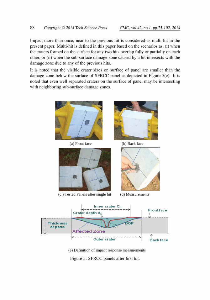
Impact more than once, near to the previous hit is considered as multi-hit in thepresent paper. Multi-hit is defined in this paper based on the scenarios as, (i) whenthe craters formed on the surface for any two hits overlap fully or partially on eachother, or (ii) when the sub-surface damage zone caused by a hit intersects with thedamage zone due to any of the previous hits.
It is noted that the visible crater sizes on surface of panel are smaller than thedamage zone below the surface of SFRCC panel as depicted in Figure 5(e). It isnoted that even well separated craters on the surface of panel may be intersectingwith neighboring sub-surface damage zones.
(a) Front face (b) Back face
(c ) Tested Panels after single hit (d) Measurements
(e) Definition of impact response measurements
Figure 5 SFRCC panels after first hit
Figure 5: SFRCC panels after first hit.

High Velocity Impact Behaviour of Layered Steel Fibre 89
3 Results and Discussions
The results of impact tests on SFRCC panels are discussed based on the measure-ment of depth of penetration, crater depth and crater dimensions. Visual inspectionis also carried out for determining the final status of the panels in terms of crack-ing and delamination. The following observations are made after investigations onimpact tested of the SFRCC panels:
3.1 Visual inspection on impact tested SFRCC panels
Crater sizes on front face of the SFRCC panels after the multi-hits within the dam-aged regions of previous hits are shown in Figure 6. The SFRCC panel with 50 mmthickness is hit only once with 5.56 mm calibre and it was perforated without anyfragmentation. Whereas the MMM type panel got fragmented under single hit of5.56 mm projectile. The diameter of crater formed in MMM type panel due to sin-gle hit is almost twice the crater diameter formed in SSS, SLS, SWS type panels.Impedance matching is only one of the conditions for smooth propagation of shockwaves through the materials. Necessarily there is a need for tensile strength andenergy absorption both of which are absent in case of MMM. Hence it shows largecrater on the front face, and fragmented into large size pieces.
Figure 6: Crater diameters on front face in few of the tested SFRCC panels (Pho-tos).

90 Copyright © 2014 Tech Science Press CMC, vol.42, no.1, pp.75-102, 2014
1. It is observed from Figure 7 that the SFRCC panels designated as SSS haveshown no cracking except the spalling on the front face at locations whereprojectile hit. Hence the concept of no impedance mismatch holds true asdemonstrated by SSS type panels, where no well defined interface existswithin the panel.
Thus the entire material (SIFCON) in SSS type panels exhibited impact per-formance like a homogenized material at macro scale. It is also noted thatthe panels have maintained better structural integrity even though the hitsare made closer to the previous hits rather within overlapping damage zonesof previous hits. The SSS type panels with 10% fibre volume show betterimpact performance.
Front faces
Back faces
Figure7 Final damage in SSS type panel under three hits
Figure 7: Final damage in SSS type panel under three hits.
2. Interface crack locations in the edge faces of SLS type panels appear at thenearer interface with respect to front face. Even though sufficient care wastaken to establish good bonding between top SIFCON layer and middle LMClayer, minor cracking could not be avoided. It is obvious that the interfacenearer to front face (I/F1-2) subject to severe impulse and the crack appearsthere as visible on edge faces (Refer Figure A.1and Figure 8). Whereas rear

High Velocity Impact Behaviour of Layered Steel Fibre 91
(far) interface (I/F2-3) subjected to the impulsive forces on a wider area ascompared to front (near) interface. It means that the entire kinetic energy ofthe projectile get dissipated in spalling and cracking at front face. In the SLStype panels interface cracks on the edge faces in addition to the front spallingare observed.
However the maximum interface crack widths measured are less than 1mm.Since the stresses developed by impulsive force due to impact is much higherthan the tensile strength of the material the spalling takes place. With properlayer arrangement, the crater size is reduced to almost half as compared tothat in panel made of plain concrete.
Front faces
Back faces
Edge faces
Figure 8: Damage in SLS type panel.
3. The SWS type panels consist of infill layers having wire meshes embedded in

92 Copyright © 2014 Tech Science Press CMC, vol.42, no.1, pp.75-102, 2014
high strength slurry. It can be observed that SWS panels exhibited interfacecracks on the edge faces as shown in Figure 9.
Location of cracking at edge face is shifted towards mid plane of panel. How-ever in case of welded mesh interface bond becomes an important issue lead-ing to slip of wire mesh. Therefore, cracking at the mid plane along theperiphery is due to bond-slip between meshed reinforcement layers.
Front faces Back faces
Figure 9: Damage in SWS type panels.
To measure internal damages zones, few of the tested composite panels arecut across the thickness using concrete cutting machine. The cross-sectionsof SFRCC panels after cutting are shown in Figure 10. It is noted that thereis no visible cracking in the core layers. It is also found that well separatedsurface craters due to multi hits get overlapped internally.
(a) SSS type (b) SLS type
Figure 10: Cross-sectional views of SFRCC panels after cutting
Figure 10: Cross-sectional views of SFRCC panels after cutting.

High Velocity Impact Behaviour of Layered Steel Fibre 93
The maximum, minimum and average values of depth of penetrations and averagecraters diameter in SFRCC panels under first hits are measured using digital Verniercaliper and furnished in Table 6.
Table 6: Results of high velocity impact test on SFRCC panels.
Designationof Panel
Projectilecalibre
Depth ofpenetration
(DOP)
Crater diameters TotalThickness
ID mm mm mm mmSSS-10% 5.56 50.0 (Perforated) 22.7 (Average) 50(2 Nos.) 7.62 50.0 (Perforated) 40.0 (Average) 50
31.60 (Max) 65.6 (Max) 100SSS-10% 5.56 24.00 (Min) 48.3 (Min) 100(3Nos.) 27.10 ( Average) 57.6 (Average) 100
41.91 (Max) 79.0 (Max) 100SSS-10% 7.62 33.17 (Min) 53.6 (Min) 100(3Nos.) 38.36 (Average) 64.9 (Average) 100
33.10 (Max) 73.9 (Max) 100SLS-10% 5.56 30.60 (Min) 48.3 (Min) 100(3Nos.) 31.72 (Average) 58.6 (Average) 100
48.08 (Max) 75.3 (Max) 100SLS-10% 7.62 32.22(Min) 52.5 (Min) 100(3Nos.) 40.50(Average) 59.1 (Average) 100
33.04 (Max) 66.5 (Max) 100SWS-10% 5.56 25.45 (Min) 49.8 (Min) 100
(3Nos.) 28.66 (Average) 56.0 (Average) 10049.70 (Max) 70.2 (Max) 100
SWS-10% 7.62 34.10 (Min) 51.2 (Min) 100(3Nos.) 40.10 (Average) 57.9 (Average) 100
1# MMM-1 5.56 Fragmented 80.0 (Average) 1001# MMM-2 7.62 Fragmented 115.0 (Average) 100
3.2 Effect of fibre volume
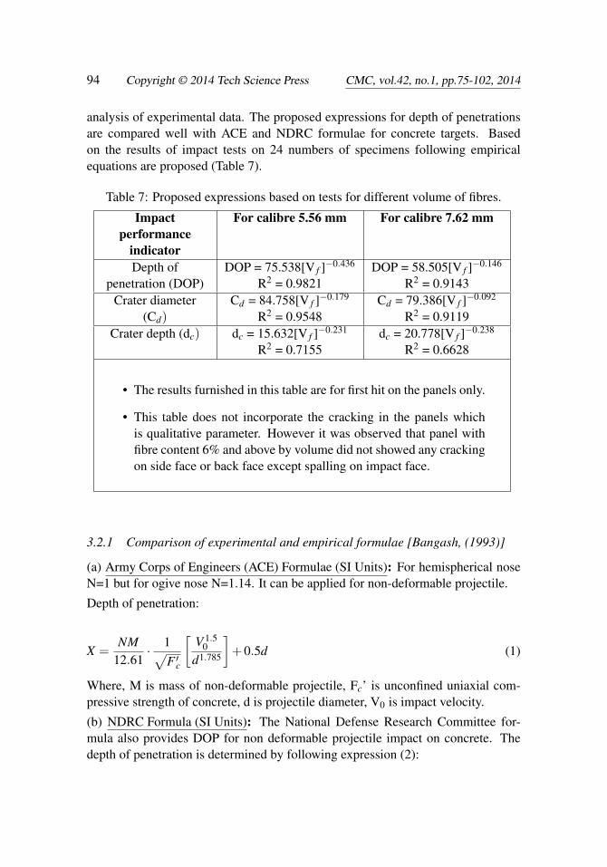
Results of SSS panels with varying fibre volumes indicate that the fibre volume lessthan or equal to 4% show cracking at the back face of panels. The crater dimensionsdo not vary much with fibre volume beyond 6%, but the depth of penetration doesshow reduction. Empirical expressions are being proposed based on the regression
94 Copyright © 2014 Tech Science Press CMC, vol.42, no.1, pp.75-102, 2014
analysis of experimental data. The proposed expressions for depth of penetrationsare compared well with ACE and NDRC formulae for concrete targets. Basedon the results of impact tests on 24 numbers of specimens following empiricalequations are proposed (Table 7).
Table 7: Proposed expressions based on tests for different volume of fibres.
Impactperformance
indicator
For calibre 5.56 mm For calibre 7.62 mm
Depth ofpenetration (DOP)
DOP = 75.538[V f ]−0.436
R2 = 0.9821DOP = 58.505[V f ]−0.146
R2 = 0.9143Crater diameter
(Cd)Cd = 84.758[V f ]−0.179
R2 = 0.9548Cd = 79.386[V f ]−0.092
R2 = 0.9119Crater depth (dc) dc = 15.632[V f ]−0.231
R2 = 0.7155dc = 20.778[V f ]−0.238
R2 = 0.6628
• The results furnished in this table are for first hit on the panels only.
• This table does not incorporate the cracking in the panels whichis qualitative parameter. However it was observed that panel withfibre content 6% and above by volume did not showed any crackingon side face or back face except spalling on impact face.
3.2.1 Comparison of experimental and empirical formulae [Bangash, (1993)]
(a) Army Corps of Engineers (ACE) Formulae (SI Units): For hemispherical noseN=1 but for ogive nose N=1.14. It can be applied for non-deformable projectile.
Depth of penetration:
X =NM
12.61· 1√
F ′c
[V 1.5
0d1.785
]+0.5d (1)
Where, M is mass of non-deformable projectile, Fc’ is unconfined uniaxial com-pressive strength of concrete, d is projectile diameter, V0 is impact velocity.
(b) NDRC Formula (SI Units): The National Defense Research Committee for-mula also provides DOP for non deformable projectile impact on concrete. Thedepth of penetration is determined by following expression (2):

High Velocity Impact Behaviour of Layered Steel Fibre 95
Depth of penetration:
X =1√F ′c· NM
104
[V0
d
]1.8
+d (2)
Parameters are same as in ACE formulae; N is nose shape factor which is 1.14 forogive nose projectiles. Using experimental value and the expressions (1) and (2) fordepth of penetration the values are compared well as shown in Table 8 and plottedin Figure 11.
Table 8: Comparison of empirical and experimental results.Volume of
fibreCompressivestrength of
Fibre
DOP (mm) Cracking at backface or edge
facesconcrete F′c For 7.62 mm calibre
% MPa ACE NDRC Experiment0 59.57 52.06 48.46 Fragmented Yes2 60.25 51.79 48.23 52.87 Yes4 74.56 46.93 44.13 47.79 Yes6 85.63 44.05 41.69 45.04 No8 98.38 41.35 39.40 43.19 No10 106.22 39.94 38.21 41.80 No
For mass M=8.0 g, V0 =720 m/s, d =7.62 mm and, N =1.14, DOPs are calculated.
Figure 11: Comparison of experimental and empirical results for 7.62 mm Projec-tile.

96 Copyright © 2014 Tech Science Press CMC, vol.42, no.1, pp.75-102, 2014
4 Conclusions
In this paper result of an experimental study highlighting the impact tests on steelfibre reinforced cementitious composite (SFRCC) panels have been presented. Ithas been found from the study that the design of impact resistant structures requiresunderstanding of both the suitable materials and physics of the phenomenon. Forthe design of layered composite panels the lay-up sequence of the materials tobe used in the layers, needs judicious selection for obtaining better impact per-formance of layered SFRCC panels. It has also been observed that SFRCC panelsexhibit desirable structural integrity even after multi-hits of short projectiles of 5.56mm and 7.62 mm calibre. The following conclusions can be drawn based on theexperiments conducted and presented in this paper:
• The concept for the selection of materials used in layers and lay-up sequencein SFRCC panels is explained. It is observed from the impact tests that theSSS type panel behave like homogenized material at macro level. Further nowell defined interface occurs for SSS type panels.
• Neither fragmentation nor scabbing at the back face is observed in the SFRCCpanels under multiple hits. Significant enhancement in impact resistance ofthe fibre reinforced composite panels is observed as compared to panels madeof plain slurry.
• Reduction in steel fibre content is achievable upto 40% in SLS type as com-pared to SSS type panels by providing latex modified concrete (LMC) infill,without any considerable loss in impact resistance of proposed SFRCC pan-els.
• The SFRCC panels, in which LMC or wire meshes are used in core layer,showed fine interface cracks nearer to the front face upon impact. While thepanel with LMC core layer exhibited only hairline interface cracks, the SWStype panels showed relatively wider interface cracks at the middle of corelayer instead of at the interface with SIFCON layers.
• It is inferred from the comparison between meshed reinforcement and ran-dom fibre reinforcement that the matrix between the reinforcement meshesexhibit weaker zone to resist tensile stresses. Hence randomly distributedshort steel fibres provide better impact resistance. However relatively moreefforts are needed in the casting of short fibre reinforced layer of SFRCCpanels than layers with meshed reinforcement.

High Velocity Impact Behaviour of Layered Steel Fibre 97
• Under the impact of 7.62 mm calibre projectiles both DOP and the cratersizes are found to slightly increase as compared to 5.56 mm calibre projec-tiles.
• The values of depth of penetration determined experimentally and empiri-cally are found to match closely for 7.62 mm projectile impact cases. TheSSS type panels with the fibre volume lesser than or equal to 4%, exhibitedpredominant cracking at both the faces.
• It is found that ACE and NDRC expressions to calculate depth of penetra-tion given for concrete can also be used for SFRCC as shown for SSS typepanels. The empirical relations are proposed for both the calibres based onthe regression analysis. However, proposed expressions for 7.62 mm projec-tile to determine depth of penetration (DOP) could only be compared withACE and NDRC formulae. Because, 7.62 mm projectile have solid steel corewhereas 5.56 mm projectile have soft Lead core and, both the expressions byACE and NDRC consider rigid projectile only.
Acknowledgement: The help rendered by staff of Advanced Material Labora-tory and Shock and Vibration Group, during casting the SFRCC panels is grate-fully acknowledged. The help and co-operation given by Dr. J. Rajasankar, Head,and Dr. (Mrs.) N. Anandavalli, project leader, Shock and Vibration group, CSIR-SERC, in fabricating the moulds and technical discussions during the field firingexperiments is gratefully acknowledged. The permission and facilities provided byauthorities of Officers Training Academy (OTA), Chennai for impact tests is highlyacknowledged. This paper is being published with kind permission of the Director,CSIR-SERC, Chennai.
Appendix A
A.1 Shock Wave Propagation in Layered SFRCC Panels
The physics of the shock wave propagation and influence of layers on its propaga-tion during impact resistance is described in this section. It is important to considermaterials such that smooth transmission of shock waves through the layers is fa-cilitated, which avoids interfacial delamination. An important reason of choosingcementitious materials in the preparation of the layered SFRCC panels is to takeadvantage of cohesiveness of similar nature materials in achieving good interfacebonds. The concept and considerations in the selection of materials for the prepa-ration of SFRCC panels investigated in this study are briefly described in the nextsub-section.
98 Copyright © 2014 Tech Science Press CMC, vol.42, no.1, pp.75-102, 2014
A.2 Effect of layers on shock wave propagation
Three main factors that influence the wave propagation [Zukas (2004)] are impedancemismatch, interface density, thickness ratio of layers. However, impact resistanceof layered composite panel depends on the loading conditions, layering sequence,materials used, and the method of its fabrication or preparation. Explicit transientsolutions for one-dimensional wave propagation behavior in multi-layered struc-tures are presented by Lin and Ma (2011). They have developed an analyticalmethod for constructing solutions in multi-layered media. The loading conditionsdepend on the geometry of projectile (bullet, pellet or ball etc.), impact angle andimpact velocity. The shock wave propagation in layered medium like SFRCC pan-els is depicted in Figure A.1. When a projectile hits the target panel, shock waveis generated at the point of impact and propagates forward direction spherically asshown in Figure A.1. Once it meets the interface between two layers of differentmaterials, there occurs both reflection and transmission of the stress wave depend-ing upon the impedance mismatch. It is depicted through thinner lines that whenshock wave propagates its attenuation takes place and as a result, it gets weaker.
For instance, shock wave [say ‘1’] undergoes through both transmission and reflec-tion at the interfaces. The forward moving shock wave (solid lines) or transmit-ted wave exerts compressive force in material whereas after reflection either fromstress free surface or interfaces, it becomes tensile wave (dotted lines). The interac-tions between transmitted and reflected shock wave continue till equilibrium stateis attained by projectile and target panels. Such multiple interactions between thetensile and compressive shock waves cause interface cracks, spalling and scabbingin target. The impedance match between layers ensures effective utilization of thetotal depth leading to reduced tensile strength on reflection from rear. Reflectionsfrom layers of lesser thickness lead to sharper tensile pulse. Due to this reasonoptimum thickness of layers are used.
Impedance ratio R= (ρC)hard /(ρC)so f t , where ρ and C represent mass density andvelocity of sound in the medium respectively. The ‘R’ is a measure of impedance ofhard layer over that of the soft layer; here ‘R’ is used to represent level of impedancemismatch and R ranges from 1 to ∞. The value of ‘R’ equal to 1, indicates thatthere is no impedance mismatch between layers. The relation between parameters,impedance mismatches I, and impedance ratio R, can be expressed as follows [Chenand Chandra (2004)]:
I =(
R−1R+1
)2
(A.1)
Chen and Chandra [22] have reported that ‘I’ is better parameter than ‘R’ to repre-sent impedance mismatch of two mediums. It is also clear from the curve plotted

High Velocity Impact Behaviour of Layered Steel Fibre 99
Initial shock wave 1 at front
face Reflected wave from I/F1-2
Reflected wave1* from I/F2-
3
Transmitted wave 1* at I/F1-
2
Transmitted wave1** at I/F 2-3
Reflected wave 1** from B/F
Index
Layer 2
ρ2, c2 , t2
Layer 3
ρ3 , c3 , t3
Layer 1
ρ1 , c1 , t1
Projectile
impact
Back face
Front face
Interface,
I/F1-2 Interface, I/F2-3
Figure A.1: Shock wave transmissions and reflections in layered SFRCC panel.
Figure A.2: Variation of I with respect to R.
using Eq. (1) as shown in Figure A.2.
It can be observed that when the impedance ratio R varies from 1 to 20, the corre-sponding change in ‘I’ is 0 to 0.82. Similarly, when R is varied from 20 to 100, Ichanges only from 0.82 to 0.961.
Delamination between layers takes place due to acoustic impedances mismatch be-tween layers in composite panels. Hence, adequate efforts are made in the presentpaper to reduce the interfacial delamination by choosing the cementitious material

100 Copyright © 2014 Tech Science Press CMC, vol.42, no.1, pp.75-102, 2014
having nearly equal acoustic impedances. In the layered SFRCC panels, interfacialbond between cementitious surfaces helps in exhibiting better performance underimpact when compared to metal/cementitious interfaces. Using eqn. (A.1) for ma-terials in adjacent layers such as SIFCON (with 10 % fibre) and LMC, it can beobserved from Table 4, that the ‘R’ is near to 1 and, I is negligible. Therefore, theselected materials evince the condition for smooth propagation of shock wave atinterface with minimum reflection.
References
ASTM Standard C39: Standard Test Method for compressive strength of cylin-drical concrete specimens.
Allan, M. L. (1997): Rheology of Latex-Modified Grouts. Cement and ConcreteResearch, vol. 7.7, no. 12, pp. 1875-1884.
Anderson, W. F.; Watson, A. J.; Kaminskyj, A. E. (1992): The resistance ofSIFCON to high velocity impact. Second Intl. Conference on Structures UnderShock and Impact, pp. 89-98.
Bangash, M. Y. H. (1993): Impact and explosion-Analysis and Design. Blackwellscientific publisher.
Barluenga, G.; Hernandez-Olivares, F. (2004): SBR Latex Modified Mortar Rhe-ology and Mechanical Behaviours. Cement and Concrete Research, vol. 34, pp.527–535.
Bindiganavile, V.; Banthia, N. (2002): Impact Response of Ultra-High-StrengthFibre Reinforced Cement Composite. ACI Materials Journal, vol. 99, no. 6, pp.543-548.
Borvik, T.; Dey, S.; Clausen, A. (2009): Perforation resistance of five differenthigh strength steel plates subjected to small-arms projectiles. International journalof Impact engineering, vol. 36, pp. 948-964.
Chen, X.; Chandra, N. (2004): The effect of heterogeneity on plane wave propa-gation through layered composites. Mechanical & Materials Engineering FacultyPublications, paper 57, (http://digitalcommons.unl.edu/mechengfacpub/57).
Dancygier, A. N. (1998): Rear face damage of normal and high-strength concreteelements caused by hard projectile Impact. ACI Structural Jl., vol. 25, pp. 291-303.
Dancygier, A. N.; Yankelevsky, D. Z. (2007): Response of high performanceconcrete plates to impact of non-deforming projectiles. Int J Impact Eng, vol. 34,pp. 1768-1779.
Farnam, Y.; Moosavi, M.; Shekarchi, M.; Babanajad, S. K.; Bagherzadeh,A. (2010): Behaviour of slurry infiltrated fibre concrete (SIFCON) under triaxial
High Velocity Impact Behaviour of Layered Steel Fibre 101
compression. cement and concrete research, vol. 40, pp. 1571-81.
Hanchak, S. J.; Forrestal, M. J.; Young, E. R.; Ehrgott, J. Q. (1992): Per-foration of concrete slabs with 48MPa (7 ksi) and 140MPa (20 ksi) unconfinedcompressive strength. Int J Impact Eng; vol. 12, No.1, pp. 1–7.
Iremonger, M. J. (2003): Disruption of small Arms bullet using thin metal plates,Proceedings of 11th international symposium on interaction of the effects of muni-tions with structures, Mannheim, Germany.
JSCE SF-4: Method of test for flexural strength and toughness of fibre reinforcedconcrete.
Kim, J. K.; Mai, Y. W. (1998): Engineered interfaces in fibre reinforced compos-ites, Elsevier Science Ltd.
Kustermann, A.; Karl-Christian, T.; Christian, B.; Manfred, K.; Rupprecht,Z. (2009): Protection elements made of High Strength Fibre Reinforced Concrete(HSFRC) as single and multi layer constructions, 12th Intl. Symposium on Inter-action of the Effects of Munitions with Structures, University of the Armed Forces,Munich Institute for Building Materials Andrea.
Lin, Y. H.; Ma, C. C. (2011): Transient Analysis of Elastic Wave Propagation inMultilayered Structures. Computers, Materials & Continua, vol.24, no.1, pp.15-42.
Luo, X.; Sun, W.; Chan, S. Y. N. (2000): Characteristics of high-performancesteel fibre-reinforced concrete subjected to high velocity impact. Cement and Con-crete Research, vol. 30, pp. 907-914.
Maalej, M.; Quek, S. T.; Zhang, J. (2005): Behaviour of hybrid-fibre engineeredcementitious composites subjected to dynamic tensile loading and projectile im-pact. Jl. of Materials in Civil Engineering, vol. 17, pp. 143-152.
Naaman, A. E.; Otter, D.; Najm, H. (1992): Elastic modulus of SIFCON intension and compression. ACI Material Jl., vol. 88, pp. 540–548.
O’Neil, E. F.; Neeley, B. D.; Cargile, J. D. (1992): Tensile Properties of very highstrength concrete for penetration-resistant structures. Shock and Vibration, vol. 6,pp. 237-245.
Quek, S. T.; Lin, V. W. J.; Maalej, M. (2010): Development of functionally-graded cementitious panel against high-velocity small projectile impact. Int J Im-pact Engineering, vol. 37, pp. 928-941.
Shah, A. A.; Ribakov, Y. (2011): Recent trends in steel fibred high-strength con-crete. Materials and Design, vol. 32, pp. 4122–4151.
Soe, K. T.; Zhang, Y. X.; Zhang, L. C. (2013): Impact resistance of hybrid-fiberengineered cementitious composite panels. Composite structures, vol. 104, pp.

102 Copyright © 2014 Tech Science Press CMC, vol.42, no.1, pp.75-102, 2014
320-330.
Tham, C. Y. (2006): Numerical and empirical approach in predicting the penetra-tion of target by an ogive-nosed projectile. Finite element in analysis and design,vol. 42, pp. 1258-68
Zai, S. A. K.; Prasad, G. L. E.; Gupta, N. K.; Munirudrappa, N.; Muthu-mani, K. (2010): Impact Behavior of SBR-latex Modified Fibre Reinforced Con-crete Beams, Proceedings of the IMPLAST 2010 Conference October 12-14 2010Providence, Rhode Island USA.
Zukas, J. (2004): Introduction to Hydrocodes, Elsevier B.V., Amsterdam, TheNetherlands.