HIGH TEMPERATURE PROCESSABLE NANOFIBROUS...
60
HIGH TEMPERATURE PROCESSABLE NANOFIBROUS INTERLAYERS FOR COMPOSITE STRUCTURES by Ayça ÜRKMEZ Submitted to Graduate School of Engineering and Natural Sciences in partial fulfillment of the requirements for the degree of Master of Science Sabancı University June, 2015
Transcript of HIGH TEMPERATURE PROCESSABLE NANOFIBROUS...

HIGH TEMPERATURE PROCESSABLE NANOFIBROUS INTERLAYERS
FOR COMPOSITE STRUCTURES
by
Ayça ÜRKMEZ
Submitted to Graduate School of Engineering and Natural Sciences
in partial fulfillment of
the requirements for the degree of
Master of Science
Sabancı University
June, 2015


i
© Ayça Ürkmez 2015
All Rights Reserved

ii
La Vita è Bella
To my beloved father
“Babama...”
iii
HIGH TEMPERATURE PROCESSABLE NANOFIBROUS INTERLAYERS FOR
COMPOSITE STRUCTURES
Ayça Ürkmez
MAT, Master of Science Thesis, 2015
Thesis Supervisor: Assoc. Prof. Dr. Melih Papila
Keywords: composite materials, nanofiber, interlayer, cross-linking, thermal behaviour
Abstract
Nano-engineering of composite materials is an expanding research field, thanks
to emerging manufacturing techniques and intriguing properties of nano-scale materials.
It requires both "multi-disciplinary" and "multi-scaled" research insight for achieving
the ultimate goal of superior material properties preferably with multifunctionality.
Enhancing the mechanical properties such as toughening is arguably the most common
interest.
Interlayer toughening of structural composite materials is one of the several
toughening mechanisms where interlaminar region, being one of the weakest links in
composite structures, is at focus for the material solution developed here. Nano-
interlayer toughening strategy thus aims to integrate nano-scaled reinforcements to
interlaminar regions in order to improve the mechanical performance with minimum
weight addition. Following this strategy, this thesis work firstly investigates the effect
of glass transition temperature on the morphology of electrospun P(St-co-GMA)
nanofibers which are proven to be a potential candidate for interlayer toughening in
composite materials thanks to their epoxy compatibility. Secondly it offers a unique

iv
way to undisrupted electrospinning of these nanofibers in the presence of crosslinking
agents. The goal is to achieve in-situ crosslinking at heat stimuli consistent with typical
cure cycles of advanced polymeric composites. The thesis work is divided into two
subsections:
Heat Stimuli Self Crosslinking of Electrospun Nanofibers: Stimuli-Self –
Crosslinking ability is introduced to P(St-co-GMA) nanofibers by the addition of
Phtalic Anhydride (PA) as cross-linking agent and tributylamine (TBA) as the catalyst.
Heat activated crosslinking procedure enables the manufacturing of cross-linkable
nanofibers through electrospinning at room temperature without any rheological
problems. A complete cross-linking event is characterized by co-use of FT-IR analysis
focusing the consumption of PA and disappearance of available active sites in
copolymer and swelling tests. Glass transition temperature of self-cross-linked
copolymers increases by 30ºC without any post chemical treatments required, elevated
temperature effect on the nanofiber morphology change before and after crosslinking is
determined by SEM analysis.
In-situ crosslinakable nanofibers for structural composites: The crosslinking
recipe optimized in the first part is offered for the incorporation of polymeric
nanofibrous interlayers into structural composites where high temperature curing cycle
is needed. The hypothesis is that heat stimuli-self crosslinking enables a homogenous
crosslinking regime both for nanofibers and epoxy matrix itself during curing which
results in better mechanical performance. Following this motivation an example case is
demonstrated where stimuli-self-crosslinkable P(St-co-GMA)/PA-TBA nanofibrous
interlayers are added to carbon/epoxy prepreg composites cured at 135°C. Interlayered
laminates are subjected to three-point bending and mode II fracture toughness tests
(end-notched flexure-ENF). Mechanical test results are accompanied by cross-sectional
and fracture surface microscopy analysis through Scanning Electron Microscopy
(SEM). As a result of mechanical tests a significant increase in resistance against mode
II delamination (80%) and flexural strength (15%) with precisely no weight penalty was
observed.
v
YÜKSEK SICAKLIK DAYANIMLI NANOLİF ARAYÜZLERİN KOMPOZİT
YAPILARA UYGULANMASI
Ayça Ürkmez
MAT, Yüksek Lisans Tezi, 2015
Tez Danışmanı: Yard. Doç. Dr. Melih Papila
Anahtar Kelimeler: kompozit malzemeler, nanolif, arayüzey, çapraz bağlanma, termal
özlellik
Özet
Kompozit malzemelerin nano-boyuttaki mühendislik çalışmaları ve
uygulamaları yaygınlaşmakta olan bir araştırma alanıdır. Araştırmacılar bahsedilen
mühendislik çalışmalarını yeni üretim yöntemleri ve son zamanlarda keşfedilen ve umut
verici özelliklere sahip olan nano-boyuttaki malzemelerle bir bütün olarak ele alıp
bunlar üzerine yoğunlaşmaktadır. Malzeme özellikleri farklı zaman ve boyut
ölçeklerinde hesaplanan nano-mühendislik ürünü kompozit malzemeler “disiplinler
arası” ve “çok-ölçekli” bir araştırma anlayışı gerektirmektedir. Yapısal kompozit
malzemelerde kullanılan “katmanlar arası güçlendirme” yöntemi birçok toklaştırma
mekanizmasından biridir ki bu laminalar arası bölge kompozit malzemelerin en zayıf
bölgesi olarak addedilmektedir ve çalışmaların odak noktasında bulunmaktadır. Nano-
katmalar arası güçlendirme stratejisi, nano ölçekli takviye malzemelerinin laminalar
arası bölgeye entegrasyonunu sağlayarak, mekanik performansı minimum ağırlık artışı
ile arttırmayı amaçlamaktadır. Bahsedilen stratejiyi baz alarak bu tez çalışmasında, ilk
olarak katmanlar arası güçlendirme potansiyeli kanıtlanmış olan P(St-co-GMA)
nanofiberlerinin morfolojisi üzerinde camsı geçiş sıcaklığının etkisi gözlenmiştir. İkincil
olarak da ısıl etki ile yerinde çapraz bağlanan ve içerisinde çapraz bağlayıcı ihtiva eden
solüsyonların sorunsuz ve devamlı elektro-dokuması sağlanmıştır. Ayrıntılandırmak
gerekirse bu tez iki alt kısım içermektedir.

vi
Isıl etki ile kendiliğinden çapraz bağlanabilen nanoliflerin elektro-
dokuması: P(St-co-GMA) nanoliflerine Stimuli-kendiliğinden-çapraz bağlanabilme
özelliği, çapraz bağlayıcı (Ftalik Anhidrid) başlatıcı (Tribtilamin) eklenerek
kazandırılmıştır. Sıcaklıkla aktive olan çapraz bağlanma prosedürü oda sıcaklığında her
hangi bir reolojik problemle karşılaşılmaksızın nanolif üretimini mümkün
kılmıştır.Çapraz bağlanma reaksiyon sonrasında ftalik anhidrid harcanmasına bağlı
olarak FT-IR spektrumunda aktif uçların kopolimer içeriğindeki epoksid halkası ile bağ
yaparak kaybolması ve şişme testleri ile karakterize edilmiştir. Nanoliflerin art kimyasal
işlem gerekmeksizin camsı geçiş sıcaklıkları 30 ºC arttırılmıştır. Çapraz bağlanma
öncesi ve sonrası morfolojik değişimler taramalı elektron mikroskobu (SEM) analizleri
ile incelenmiştir.
Yerinde çapraz bağlanabilen nanoliflerin yapısal kompozitlere uygulaması:
Termal stabilite çalışmalarında oluşturulan çapraz bağlanma reçetesi P(St-co-GMA)
nanofibelerinin camı geçiş sıcaklıklarının aşılması gereken kürlenme prosedürüne sahip
yapısal kompozitlere polimerik nanolif olarak uygulanmak üzere bir çalışma
oluşturulmuştur. Hipotez stimuli-kendiliğinden-çapraz bağlanabilen nanoliflerin
kürlenme sırasında hem kendi aralarında hem de kompozit içerisinde epoksi ile
homojen biçimde çapraz bağlanarak geliştirilmiş mekanik özellik elde etmeyi
amaçlamak olarak özetlenebilir. Bu motivasyonla stimuli-kendiliğinden-çapraz
bağlanabilen P(St-co-GMA)/PA-TBA ve 150 ºC üzerinde çalışabilen nanolifleri yapısal
kompozitlere arayüzey olarak uygulanarak bir deneyler serisi planlanmıştır.
Arayüzeylerle katkılandırılmış yapısal kompozitler 3-nokta eğme, düz-kesme
kuvvetlerine maruz bırakılmıştır. Mekanik test sonuçları enine kesit ve kırılma yüzeyleri
üzerinden taramalı elektron mikroskobu ile incelenmiştir. Yapılan mekanik testlerin
sonucunda görülmüştürki mod II delaminasyon mukavemetinde % 80’ e varan bir artış
gözlenmiş bununla beraber eğilme mukavemetinde % 15 oranında iyileşme gözlenmiştir
ve bu sonuçlar belirgin bir ağırlık artışı olmadan sağlanmıştır.

vii
Acknowledgements
Though only my name appears on the cover of this dissertation, a great many
people have contributed to its production. I owe my gratitude to all those people who
have made this dissertation possible and because of whom my graduate experience has
been one that I will cherish forever.
First and foremost I would like to express my heartfelt gratitude to my
supervisor Assoc. Prof Dr Melih Papila for his academic guidance, continuous support
and encouragement throughout this project. He always illuminated me when I had
problems and difficulties during the experimental and composing works of my MSc.
I would also like to thank Prof. Dr. Ali Rana Atılgan and Assoc. Prof. Dr. Nuri
Ersoy for serving as defense committee members also for their valuable comments and
reviews.
I am thankful to TUBITAK for providing me scholarship and project funding
(TUBITAK 213M542) during my thesis.
I would to extend my sincere thanks to Dr. Kılıçaslan Noyan Bayraktar for being
a guide to me in every division in life.
I also would like to extend my sincere thanks to Prof. Dr. Mehmet Ali Gülgün
for his encouragement and support.
I want to also express my appreciation towards all my present and former
colleagues at the division of Material Science & Engineering for the nice working
environment, which has made my time at the SU most pleasant. My deepest gratitude
goes to my dearest colleague Kaan Bilge for his endless help, input, and friendship
throughout my MSc years. I would like to thank our group members Bengisu Yılmaz
and Farzin Javanshour for their support. I would like also thank to Elif Özden Yenigün,
Eren Şimşek, Mustafa Baysal and Turgay Gönül for their help during my research.
Though I cannot possibly list them all, I offer my special thanks to all SU members.
I would like to thank Tuğçe Akkaş for her kind friendship and all the laughter
we shared.

viii
I would like to extend my sincere thanks to Dilay Ünal, whom I can always
share my feelings and secrets for her endless help as a sister till the very first day of the
SU.
I would like also to thank Güliz İnan Akmehmet for sharing, cheering,
supporting me and most of all being a second family to me in İstanbul with her kind
husband Celal.
I would like to thank Boğaç Poyraz for beautifying my life with a priceless
balloon which I want to carry for the rest of my life.
Most importantly, none of this would have been possible without the love and
patience of my family. My immediate family has been a constant source of love,
concern, support and strength all these years. I would like to express my heart-felt
gratitude to my family, firstly a part of me my sister, who I know will always be there
no matter what, to sharing all the best and worst times and converting them
unforgettable memories to remember with a smile on our faces and to my brother for his
existence and support mostly for his never ending energy to cheer me, especially to my
father to whom this thesis dedicated to, for both being a mother and a father to us
tirelessly through all these years. I would like to express my wholehearted love and
thanks to my heavenly mother all the invisible love and support of her that I feel
whenever I need.
ix
TABLE OF CONTENTS
CHAPTER 1 .................................................................................................................... 1
1.1 General Introduction .......................................................................................... 1
CHAPTER 2 .................................................................................................................... 3
MATERIAL DEVELOPMENT .................................................................................. 3
HEAT CONTROLLED STIMULI-SELF-CROSSLINKING OF ELECTROSPUN
NANOFIBERS .............................................................................................................. 3
2.1 Introduction ........................................................................................................ 3
2.2 Experimental Procedure ..................................................................................... 6
2.2.1 Copolymer Synthesis .................................................................................. 6
2.2.2 Process Optimization for Electrospinning of Stimuli-Self-Crosslinkable
P(St-co-GMA) nanofibers ......................................................................................... 7
2.2.3 Crosslinking of Stimuli-Self-Crosslinkable P(St-co-GMA) nanofibers ..... 9
2.2.4 Characterization of Electrospun Nanofibers ............................................. 11
2.3 Results and Discussions ................................................................................... 12
2.3.1 Electrospinability of Stimuli-Self-Crosslinkable P(St-co-GMA)/PA-TBA
Nanofibers ............................................................................................................... 12
2.3.2 Solvent Resistance of P(St-co-GMA)/PA-TBA Nanofibers .................... 13
2.3.3 Spectroscopic Characterization of P(St-co-GMA) and P(St-co-GMA)/PA-
TBA Nanofibers ...................................................................................................... 14
2.3.4 Thermal Stability of P(St-co-GMA) and P(St-co-GMA)/PA-TBA
Nanofibers ............................................................................................................... 16
2.3.5 Morphplogical characterisation of P(St-co-GMA) and P(St-co-GMA)/PA-
TBA Nanofibers ...................................................................................................... 18
2.4 Concluding Remarks ........................................................................................ 23
CHAPTER 3 .................................................................................................................. 24
DEMONSTRATION ON COMPOSITES .................................................................. 24
STRUCTURAL COMPOSITES HYBRIDIZED WITH EPOXY COMPATIBLE IN-
SITU CROSS-LINKED POLYMER NANOFIBROUS INTERLAYERS ................ 24

x
3.1 Introduction ...................................................................................................... 24
3.2 Experimental Procedure ................................................................................... 28
3.2.1 Electro-spinning and Laminate Manufacturing ........................................ 28
3.2.2 Mechanical Testing ................................................................................... 29
3.2.3 Surface and Cross Sectional Characterization .......................................... 31
3.3 Results and Discussion ..................................................................................... 32
3.3.1 Optimization of Reinforcing Nanofibrous Layer Amount ....................... 32
3.3.2 Structural Compatibility of Stimuli-Self-Crosslinkable P(St-co-
GMA)/PA-TBA interlayers and Epoxy ................................................................... 34
3.3.3 Flexural Performance by 3-Point-Bending Tests ...................................... 36
3.3.4 Mode II Strain Energy release rate by ENF Tests .................................... 38
3.4 Concluding Remarks ........................................................................................ 41
REFERENCES ............................................................................................................ 42

xi
LIST OF FIGURES
Figure2.1: Schematic representation of Poly(Styrene-co-Glycidylmethacrylate)
synthesis ............................................................................................................................ 7
Figure 2.2: Illustration of electrospinning set-up ............................................................ 9
Figure 2.3: Proposed reaction route for crosslinking of P(St-co-GMA)/PA-TBA ........ 10
Figure 2.4: Crosslinked P(Stco-GMA)/PA-TBA nanomats in DMF after 72 hours (R:2)
........................................................................................................................................ 14
Figure 2.5: FT-IR spectrum of P(St-co-GMA) (R:0), self-crosslink-able (sc) and cross-
linked (c) P(St-co-GMA)/PA-TBA nanofibers. Each row includes self-cross-linkable
(above) and cross-linked (below) nanofibers’ spectrum pairs for an identical
PA/Epoxide ring ratio marked at the right column of the graph. Shaded areas involve
characteristic bands of the system. ................................................................................. 15
Figure2.6: The cure cycle of P(St-co-GMA)/PA-TBA nanofibers. (R:2) First heating
cycle represented by red line and the second one shown by blue line. (Cross-linking
Onset: 65 ºC, Peak: 125 ºC, End: 150 ºC ) ..................................................................... 16
Figure 2.7: DSC curves of uncross-linked P(St-co-GMA) (a, R:0) and crosslinked(b-g)
P(St-co-GMA)/PA-TBA nanofibers. PA to epoxide ring ratio (R) for b-g 0.5, 1, 1.5, 2,
5, 10 respectively. ........................................................................................................... 17
Figure 2.8: SEM micrographs of electrospun fibers. Each row includes SEM images of
the fibers with an identical PA/Epoxide ring ratio. Each raw includes SEM images of
the fibers prior to heat treatment (left), after heat treatment at 90 ºC 2h (center), post
heat treatment at 150 ºC (right). ( for a,b,d-l scale bar: 2μm and for c scale bar: 20μm)
(Nanofiber diameter distribution chart present fiber diameters from 100 to 800nm and
each column represent a hundred nm range also distribution graphs include the highest
bar’s scale below) ........................................................................................................... 19
Figure2.9: SEM micrographs of P(St-co-GMA) and P(St-co-GMA)/PA-TBA
nanofibers’ prepared by dual syringe technique ............................................................. 20
Figure 2.10: SEM micrographs of P(St-co-GMA)/PA-TBA nanofibers with PA/GMA
ratios R:1 and R:5 after immersion in DMF 72 h. (For neat samples please see figure
2.8) .................................................................................................................................. 21
Figure 3.1: Illustration of the electro-spinning over the prepreg plies .......................... 28

xii
Figure 3.2: Vacuum Bagging and Curing Process ......................................................... 29
Figure 3.3: Three-point bending test configurations and lamination sequences ........... 30
Figure 3.4: ENF test configuration ................................................................................ 31
Figure 3.5: Influence of reinforcement amount on flexural properties ......................... 33
Figure 3.6: P(St-co-GMA) (left) and Stimuli-Self-Crosslinkable (right) Nanofibers onto
prepreg surfaces cured at 135 ºC (Magnifications: 500, 1K, 5K) ................................... 34
Figure 3.7: Nanofibrous mat over prepreg layers (P(St-co-GMA) nanofibers at left,
Stimuli-self-crosslinkable P(St-co-GMA)/PA-TBA nanofibers at right) ....................... 35
Figure 3.8: Representative 3-Point Bending test curves for (0)3 laminates ................... 36
Figure 3.9: Representative cross-sectional view for fractured 3-point bending
specimens both include transverse matrix cracking (1) and delamination (2) ............... 37
Figure 3.10: Representative ENF test curves for (0)48 laminates .................................. 38
Figure 3.11: Fracture surfaces of P(St-co-GMA) and Stimuli-Self crosslinked
Nanofiber interlayered interface. Zoomed in views for encircled areas for each
interlayer. (Magnifications: 500, 1K, 5K) ...................................................................... 39
Figure 3.12: Fracture surfaces of neat interface ............................................................ 39
xiii
LIST OF TABLES
Table 2.1: Benchmarking of state-of-the-art techniques, and their main drawbacks ...... 5
Table 2.2: Process optimization route for Electrospinning of Self-Crosslinkable
nanofibers .......................................................................................................................... 8
Table 2.3: Electrospinability of different solutions ....................................................... 13
Table 2.4: Cross-linking ratio of P(St-co-GMA) nanomats among their crosslinking
agent ratio (PA/GMA) .................................................................................................... 14
Table 2.5: Average fiber diameter distributions ............................................................ 20
Table 2.6: Average fiber diameter distributions before and after the swelling tests ..... 22
Table 3.1: Literature review for nanofiber interlayered studies .................................... 26
Table 3.2: Cure cycles that subjected to structural composites .................................... 29
Table 3.3: 3-Point Bending test results for optimization ............................................... 32
Table 3.4: 3-Point Bending test results .......................................................................... 37

1
CHAPTER 1
1.1 General Introduction
Nano-scaled engineering of composite materials is an actively broadening
research field with emerging manufacturing techniques and newly discovered nano-
scale materials with promising properties. Nano-engineering of composite materials
both requires a "multi-disciplinary" and "a multi-scaled" research insight where material
properties are evaluated at different time and length scales. Interlayer toughening of
structural composite materials is one of the several toughening mechanisms where
interlaminar region, being one of the weakest links in composite structures, is at focus.
Nano-interlayer toughening strategy thus aims to integrate nano-scaled reinforcements
to interlaminar regions aiming to improve the mechanical performance with minimum
weight addition. Following this strategy, this thesis work firstly investigates the effect
of glass transition temperature on the morphology of electrospun P(St-co-GMA)
nanofibers which are proven to be a potential candidate for interlayer toughening in
composite materials thanks to their epoxy compatibility. Secondly it offers a unique
way to continuous electrospinning of these nanofibers in the presence of crosslinking
agents which are to be crosslinked in-situ with heat stimuli. More specifically, the thesis
is divided into two subsections:
Heat Stimuli Self Crosslinking of Electrospun Nanofibers: In structural
composites nano-scaled interlayer integration to the system are expected to enhance
mechanical properties at a negligible weight penalty. Nanofibers produced by the
manufacturing technique electrospinning. The polymer characteristics of the electrospun
nanofibers should be designed carefully to enable compatibility with the polymer matrix
chemistry and stability at cure conditions. Chapter 2 investigates Stimuli-self-
crosslinking ability of P(St-co-GMA) nanofibers and proposed a route for
croslinking by the addition of Phthalic Anhydride (PA) as cross-linking agent
and tributylamine (TBA) as the catalyst. Heat activated crosslinking procedure enabled

2
the manufacturing of cross-linkable nanofibers through electrospinning at room
temperature without any rheological problems. A complete cross-linking event is
characterized by co-use of FT-IR analysis focusing the consumption of PA
and disappearance of available active sites in copolymer and swelling tests. Glass
transition temperature of self-cross-linked copolymers increased by 30ºC without any
post chemical treatments required, elevated temperature effect on the nanofiber
morphology change before and after crosslinking is determined by SEM analysis.
In-situ crosslinakable nanofibers for structural composites: Polymeric
nanofiber interlayer reinforcements are considered as an encouraging strategy to
toughen structural composite materials for both under in-plane and out-of-plane
conditions. Thermally stable polymeric nano-fibrous interlayer morphology which is
enabling wetting and interfacial compatibility with the matrix epoxy system has impact
on the reinforcement performance. Therfore, investigated crosslinking recipe at the first
case was offered for the application of polymeric nanofibers to structural composites
where a high temperature curing above glass transition temperature of the polymer was
needed. The hypothesis is that heat stimuli-self crosslinking enables a homogenous
crosslinking regime both for nanofibers and epoxy matrix itself during curing which
results in better mechanical performance. Following this motivation an example case is
demonstrated where stimuli-self-crosslinkable P(St-co-GMA)/PA-TBA nanofibers are
added to carbon/epoxy prepreg composites whose curing cycle demands 150°C
application, as interlayers. Interlayered laminates are subjected to three-point bending,
open-hole tensile and mode II shear tests. Mechanical test outputs are supported with
cross-sectional and fracture surface microscopy analysis through Scanning Electron
Microscopy.

3
CHAPTER 2
MATERIAL DEVELOPMENT
HEAT CONTROLLED STIMULI-SELF-CROSSLINKING OF
ELECTROSPUN NANOFIBERS
2.1 Introduction
With better understanding of electrospinning process and emerging high
technology systems the use of electrospun nanofibers increased significantly especially
in nanocomposite [1-3], membrane [4] and structural applications [5-8] where these
materials are used either as they are or in an accompanying matrix material
(Nanocomposites). The key point in the application of these materials is the controllable
morphology[9, 10] with usually very high surface areas [2]. Also as exemplified on the
recent works of the group their chemistry is tunable to match with the matrix material
which is especially important for nanocomposite applications [1]. However, fiber
morphology can easily be affected from two external factors such as solvent and
temperature exposure. Chemical crosslinking which is either applied externally to
already electrospun nanofibers by exposure of mats to a crosslinking medium [1, 11, 12]
or initiated in-situ by the introduction of crosslinking agents to polymer solutions [13-
18], is an effective way to deal with these known problems. Ex-situ crosslinking herein
can be classified as more conventional and direct way to achieve crosslinking by
permanently changing the nanofiber chemistry. Whereas, in situ crosslinking

4
methodology is recently a new and more controllable bulk crosslinking technique which
requires an initiation event (heat, UV etc.) that is tunable according the type of
application by the correct choice of polymer and crosslinking agents.
Having derived from the nanofiber compatibility works of our group on
nanocomposites [1, 3]and structural composites [6-8], current work addresses to a
relatively less addressed problem of Tg and its effects on P(St-co-GMA) nanofibers
which is proven to be an epoxy compatible and ex-situ crosslinkable base polymer
thanks to the presence of GMA groups. The thermal stability of the functional epoxide
group containing P(St-co-GMA) nanofibers by implementing in-situ post-activated
cross-linking mechanism for the ease and sustainability of the process. Chemical cross-
linking is provided incorporation with an anhydride chemical cross-linking agent,
phthalic anhydride which is react-able with epoxide group, and an appropriate tertiary
amine catalyst, tributylamine, to produce stimuli-self-crosslinkable P(St-co-GMA)
electrospun nanofibers and chemical crosslinking with heat treatment at intermediate
temperature[19-22]. With this method, the crosslinking at room temperature was totally
avoided and viscosity problem during electrospinning which is a problematic [18] is
overcome. The optimization of crosslinking aiming to achieve maximum Tg and
minimum morphological change upon its excession was done by altering the PA to
epoxide ring mole to mole ratio from 0.5:1 to 5:1 for five different stoichiometric ratios
(R) while keeping the polymer and TBA concentrations constant.

5
Table 2.1: Benchmarking of state-of-the-art techniques, and their main drawbacks
Cross-linking type Drawbacks E
x-s
itu
Exposing an electrospun fiber mat to a fluid
cross-linking medium (liquid or vapor), or
spraying a cross-linking agent thereon
- Time consuming.
- Causes substantial
morphological changes.
In-s
itu
Processes requiring an
additional set-up
Using an UV-
light source
- Restricted with UV-curable
polymers.
- Requires additional
equipment.
Using a dual-
syringe reactive
cross-linking
set-up
- Additional viscosity
modifiers and removal of
them.
- Time consuming.
Post-electrospinning treatment Heat treatment
- Curing temperature
restrictions and related
morphological changes based
on the glass-transition
temperature (Tg) of the
polymer.
Single step in-situ cross-linking
- Viscosity changes during
electrospinning.
- Time-dependent procedure.

6
2.2 Experimental Procedure
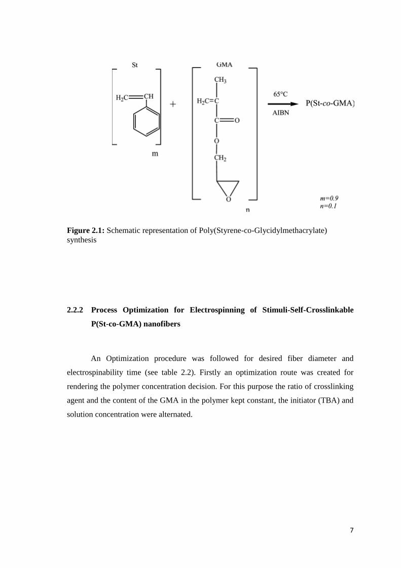
2.2.1 Copolymer Synthesis
The purified monomers of styrene (St) and glycidylmethacrylate (GMA),
solvents dimethylformamide and methanol, initiator azobisisobutyronitrile (AIBN) were
purchased from Aldrich Chemical Co. Solution polymerization technique was used for
copolymer poly(St-co-GMA) (see Figure 2.1) synthesis. Styrene and GMA (by mole
fractions m=0.9 styrene and n=0.1 GMA) were mixed at the round bottom reaction flask
contained in an ice bath. Dimetylformamide (DMF) was then added into reaction flask
with a 3:2 volume proportion solvent to monomer. The initiator AIBN was then added
in to monomer solvent mix and the reaction flask flushed with nitrogen.
The tube containing the dissolved monomers was then kept for 5 days in the
constant temperature bath at 65˚C for the polymerization reaction. Finally, the polymer
solution was poured out by drop wise into a beaker containing methanol and the
methanol/polymer mixture was filtered and dried in a vacuum oven at 60˚C for 1 day.
The synthesized P(St-co-GMA) copolymer structure was determined by proton
magnetic resonance spectroscopy (1H-NMR). Molecular weights and polydispersities
(PDI) were measured by a gel permeation chromatography (GPC) system and the
molecular weight recorded as 220,000 g/mole with 1.54 PDI.
7
Figure 2.1: Schematic representation of Poly(Styrene-co-Glycidylmethacrylate)
synthesis
2.2.2 Process Optimization for Electrospinning of Stimuli-Self-Crosslinkable
P(St-co-GMA) nanofibers
An Optimization procedure was followed for desired fiber diameter and
electrospinability time (see table 2.2). Firstly an optimization route was created for
rendering the polymer concentration decision. For this purpose the ratio of crosslinking
agent and the content of the GMA in the polymer kept constant, the initiator (TBA) and
solution concentration were alternated.

8
Table 2.2: Process optimization route for Electrospinning of Self-Crosslinkable
nanofibers
GMA
content
in
polymer
(% mol)
Initiator ratio
(TBA/Polymer
by weight)
Solution
concentration
(Polymer/DMF
by weight)
Crosslinking
agent ratio
(PA/GMA
functional
group ratio)
%10
2%
10% 2
15% 2
20% 2
30% 2
4%
10% 2
15% 2
20% 2
30% 2
Polymer solutions were prepared by dissolving P(St-co-GMA) 10, 15, 20, 30% (by
weight) in DMF and stirring for 1 hour. After P(St-co-GMA) dissolved entirely 2 or
4% of catalyst tributylamine (TBA) and PA/Epoxide ring molar ratio (R) was kept
constant for all samples as R: 2 and were added to copolymer solution and magnetically
stirred for 30 minutes. An electrical bias potential (via Gamma high voltage ES 30P-
20W) was applied to polymer solutions contained in 2 mL syringe, which has an
alligator clip attached to the blunt stainless steel syringe needle (diameter 300 µm). The
ground collector covered with aluminum foil and a syringe pump (NewEra NE-1000
Syringe Pump) was used. The applied voltage, solution flow rate and tip to ground
distance were set at 15 kV, 0.4 ml/h, and 10 cm respectively during electrospinning.
The polymer solution was electrospun onto the aluminum foil to obtain nonwoven fiber
mats.

9
Figure 2.2: Illustration of electrospinning set-up
After solution concentration optimization was concluded. Optimized parameters kept
constant and then calculated amounts of [PA/Epoxide ring molar ratio (R) is 0.5,1, 1.5,
2, 5, for 5 different samples] cross-linking agent Phthalic Anhydride (PA) were added to
copolymer solution and the electrospinning procedure was repeated as mentioned
above.
2.2.3 Crosslinking of Stimuli-Self-Crosslinkable P(St-co-GMA) nanofibers
The P(St-co-GMA) electrospun nanomats were cross-linked with post-heat-
treatment by putting into an oven; the curing cycle was 2 hours at 90 ºC (just below
polymer Tg to prevent morphological changes ) and ramping 150 ºC with 2 ºC/min and
keeping 1 hour at that temperature. The cross-linked fibers are called hereafter as P(St-
co-GMA)/PA-TBA.
The proposed reaction route for P(St-co-GMA)/PA-TBA for the cross-linking is
given in Figure 2.3. The reaction route for the epoxide and anhydride at presence of
tertiary amine was described by Fischer[20]. Initiation of the reaction occurred by the
activation of anhydride with tertiary amine to form carboxyl anion and carboxyl anion is
reacted with the epoxide then generated an alkoxide anion to enable further reaction
with the anhydride.

10
Figure 2.3: Proposed reaction route for crosslinking of P(St-co-GMA)/PA-TBA
as-spun nanofibers.

11
2.2.4 Characterization of Electrospun Nanofibers
2.2.4.1 Solvent Resistance Measurement
The degree of cross-linking determination was performed by sol-gel analysis.
P(St-co-GMA)/PA-TBA crosslinked fibers put in to an aggressive solvent (DMF) and
kept soaked for 72 hours at room temperature. The swollen fibers were then cleaned
with DMF and deionized water subsequently fibers were dried in a vacuum oven at 70
ºC. The experiments were performed with 5 pieces of the respective samples and then
the extracted data were used as average in results and discussion section.
[
] (2.1)
(2.2)
As a measure of cross-linking ratio gel fraction was calculated as in function 2.1 and 2.2
where is the initial dry mass of sample and is the dry mass of the extracted
sample [1].
2.2.4.2 Spectroscopic Analysis
The structures of stimuli-self-crosslinkable and crosslinked P(St-co-GMA)/PA-
TBA nanofibers were characterized by Attenuated Total Reflection Fourier Transform
Infrared Spectroscopy (ATR-FTIR). Analyses were performed with Thermo Scientific
iS10 FT-IR Spectrometer in the mid-infrared 4000 cm −1
to 550 cm-1
.
2.2.4.3 Differential Scanning Calorimetry
The thermal properties of P(St-co-GMA), stimuli-self-cross-linkable P(St-co-
GMA)/PA-GMA and cross-linked P(St-co-GMA)/PA-GMA nanofibers were
characterized with Differential Scanning Calorimeter (Netzsch DSC 204). Thermal

12
characterization of stimuli-self-crosslinkable nanofibers were done with a two dynamic
cycle from 25 to 250 ºC. After then the glass transition (Tg) of previously crosslinked
nanofibers were determined by means of one cycle dynamic scan from 25 to 250 ºC
after crosslinking by cycle as mentioned before.
2.2.4.4 Morphologic Analysis
The morphologies of self-cross-linkable P(St-co-GMA) and cross-linked P(St-
co-GMA)/PA-TBA electrospun mats was observed with a scanning electron microscope
containing field emission gun (SEM LEO 1530VP) using secondary electron detector
and in-lens detector at 2-5 kV after coating with Au-Pd for better electrical conduction.
The diameter analyses of nanofibers were determined using ImageJ software analysis.
2.3 Results and Discussions
2.3.1 Electrospinability of Stimuli-Self-Crosslinkable P(St-co-GMA)/PA-TBA
Nanofibers
Electro-spinning of initiator and crosslinking agent containing polymer solutions
is demanding procedure to avoid premature cross-linking. The premature cross-linking
may occur because of the temperature increase during magnetic stirring or effect of the
high shear rate during electro-spinning. Therefore, we had initially focused on the
electrospinability time of solutions. The collected data is given in Table 2.3.
Consequently, the concentrated solutions and low concentrated also low viscous
solutions were not able to be electrospun continuously. Additionally, the high initiator
amount cause extreme viscosity changes and electrospinning were not achieved.
Finally, solution which had 15% solution concentration and 2% Initiator ratio
(TBA/Polymer by weight) and 0,2% Crosslinking agent ratio (PA/GMA functional
group ratio ‘R’) was chosen as ideal solution among the other trials therefore, further
experiments were done with these optimized parameters.

13
Table 2.3: Electrospinability of different solutions
GMA
content in
polymer
(% mol)
Initiator ratio
(TBA/Polymer
by weight)
Solution
concentration
(Polymer/DMF
by weight)
Crosslinking
agent ratio
(PA/GMA
functional
group ratio
‘R’)
Nanofiber
formation
Electrospinability
time
%10
0,2%
10% 2 X 0
15% 2 >5 hours
20% 2 <1 hour
30% 2 X 0
0,4%
10% 2 X 0 15% 2 X 0 20% 2 X 0 30% 2 X 0
2.3.2 Solvent Resistance of P(St-co-GMA)/PA-TBA Nanofibers
It is known that functional group (epoxide ring), polymer, cross-linker (PA) and
catalyst (TBA) concentrations are the parameters for the cross-linking reaction [18, 23,
24]. We altered the PA to epoxide ring mole to mole ratio from 1:1 to 10:1 for five
different stoichiometric ratios (R) while keeping the polymer and TBA concentrations
constant.
The solvent resistance analyses showed that gel fraction of cross-linked fibers
was between 95%-98.3% whereas P(St-co-GMA) nanomats were completely soluble in
DMF solutions also again stimuli-self-crosslinkable P(St-co-GMA)/PA-TBA nanomats
were entirely dissolved when putting into DMF solvent system before they were heat
treated.
The cross-linking ratio of the P(St-co-GMA) nanomats is given in table 2.4. The
weight loss is comparable, with an increasing amount of crosslinking agent ratio the
crosslinking ratio increases till %98.3. Nevertheless among the five different
crosslinking agent ratio there is not a significant gel fraction differences.

14
Table 2.4: Cross-linking ratio of P(St-co-GMA) nanomats among their crosslinking
agent ratio (PA/GMA)
Crosslinking agent ratio (PA/GMA
functional
group ratio by mole fraction ‘R’)
Crosslinking ratio
(% Gel Fraction )
R:0 0
R:1 95
R:2 97.7
R:5 98.2
R:10 98.3
Figure 2.4: Crosslinked P(Stco-GMA)/PA-TBA nanomats in DMF after 72 hours (R:2)
2.3.3 Spectroscopic Characterization of P(St-co-GMA) and P(St-co-GMA)/PA-
TBA Nanofibers
FT-IR measurements performed prior to heat treatment and after the cross-
linking to structurally verify the cross-linking of self-cross-linkable P(St-co-GMA)/PA-
TBA nanofibers. Figure 2.5 shows the FT-IR spectra for P(St-co-GMA), self-cross-
linkable and cross-linked P(St-co-GMA)/PA-TBA nanofibers. Each row includes self-
cross-linkable and cross-linked nanofibers’ spectrum pairs for an identical PA/Epoxide
ring ratio. The characteristic bands of the reaction are at 1851 cm-1
and 1787 cm-1
[νs,(C=O) and νas,(C=O) of the anhydride ring], 902 cm-1
[νs,(C-O) overlapping epoxide (907
cm-1
) and anhydride (902 cm-1
) absorptions]. The intensities of the mentioned peaks
decrease due to the reacting species during the cross-linking, aforesaid peak intensities

15
also increases with the increasing PA/Epoxide ring ratio from 0.5 to 10 among the self-
cross-linkable nanofibers. Also the characteristic epoxide ring stretching at 902 cm-1
becomes distinguishable after the cross-linking reaction due to the remaining oxirane
ring moiety, these moieties decaying with the increasing PA/Epoxide ring ratio due to
increasing extent of the cross-linking. Additionally intensity of the peak at 1727 cm-1
[νs,(C=O) ester] increases with the formation of the ester groups, which is also a proof of
cross-linking[21, 25, 26].
2000 1800 1600 1400 1200 1000 800
C
SC
SC
C
C
SC
R:5
R:2
R:1
%T
ransm
itta
nce
Wavelength (cm-1
)
R:0
Figure 2.5: FT-IR spectrum of P(St-co-GMA) (R:0), self-crosslink-able (sc) and cross-
linked (c) P(St-co-GMA)/PA-TBA nanofibers. Each row includes self-cross-linkable
(above) and cross-linked (below) nanofibers’ spectrum pairs for an identical
PA/Epoxide ring ratio marked at the right column of the graph. Shaded areas involve
characteristic bands of the system.

16
2.3.4 Differential Scanning Calorimetry of P(St-co-GMA) and P(St-co-
GMA)/PA-TBA Nanofibers
Crosslinking is an exothermic reaction. For this reason to show heat treatment
initiate the cross-linking process in our case a cure cycle were applied to untreated P(St-
coGMA)/PA-TBA nanofibers. Figure 2.6 shows the reaction graphic for P(St-co-
GMA)/PA-TBA nanofibers ( R:2). The first heating cycle demonstrate that the
exothermic reaction was acquired and the onset, peak and end temperatures are 65 ºC,
125 ºC, 150 ºC respectively. Sequentially the second heat cycle did show neither an
exothermic reaction nor an endothermic reaction it only shows a glass transition
temperature (Tg: 135 ºC). According to these characteristics the cross-linking reaction
occurs exothermically, subsequent cycle shows after a heating cycle there is not an
exothermic reaction pattern, therefore it can be said that the cross-linking reaction
totally ended up.
Figure2.6: The cure cycle of P(St-co-GMA)/PA-TBA nanofibers. (R:2) First heating
cycle represented by red line and the second one shown by blue line. (Cross-linking
Onset: 65 ºC, Peak: 125 ºC, End: 150 ºC )

17
DSC thermograms of cross-linked P(St-co-GMA)/PA-TBA and un-cross-linked
P(St-co-GMA) nanofibers were carried out in order to identify the effects of the cross-
linking on the thermal transitions of P(St-co-GMA) nanofibers (Figure 2.7). Self-
crosslinkable P(St-co-GMA)/PA-TBA nanofibers were cured in an oven with a heating
cycle which were not higher than the glass transition temperature of un-crosslinked
P(St-co-GMA) nanofibers.
Figure 2.7: DSC curves of uncross-linked P(St-co-GMA) (a, R:0) and crosslinked(b-g)
P(St-co-GMA)/PA-TBA nanofibers. PA to epoxide ring ratio (R) for b-g 0.5, 1, 1.5, 2,
5, 10 respectively.
Glass transition temperature of nanofibers enhance from 98 ºC (P(St-co-GMA))
to 128 ºC with the increasing PA/ Epoxide ring ratio up to 5 due to decreasing flexibility
of polymer chains with the increasing extent of the cross-linking. After that point
further increment of the cross-linker does not increase the glass transition temperature
since the cross-linking ratio does not get higher with addition of extra PA.
Additionally, the difference between the glass transition temperatures of
nanofibers which were cured in DSC and in an oven should be discussed. The reaction
medium for the DSC case was inert and very stable but in oven conditions the reaction
occurred in air medium and was not stable as DSC. The inertness and stability could

18
possibly cause a superior ability to reaction due to enhanced network, and consequently
glass transition temperature of DSC cured nanofibers is higher.
2.3.5 Morphplogical characterisation of P(St-co-GMA) and P(St-co-GMA)/PA-
TBA Nanofibers
Fiber morphologies of P(St-co-GMA), self-cross-linkable and cross-linked
nanofibers are examined for the selected PA/Epoxide ring ratios. The morphologies of
nanofibers prior to heat treatment, after heat treatment 90 ºC (below the Tg of the fibers)
for 2h and post heat treatment at 150 ºC (above the Tg of the fibers) for 1 hour shown
with the additional fiber diameter distribution charts in figure 2.7. Morphological
analyses confirm that the fibrous morphology is obtained for the selected
electrospinning parameters. Additionally SEM images of the nanofibers prior to heat
treatment demonstrate that bead free, randomly oriented continuous fiber formation was
achieved. After the heat treatment at 90 ºC fiber morphology remained intact however
shrinkage observed it can be ascribed to the conformational changes of the polymer
chains and/or to release of the solvent molecules during heat treatment[16]. Further heat
treatment at 150ºC cause morphological changes for uncross-linked and cross-linked
fibers because the temperature higher than the glass transition temperature of
nanofibers.P(St-co-GMA) nanofibers which are uncross-linked could not maintain their
fibrous structure over their Tg (see Figure 2.7 c). Above the Tg of the fiber webs the
softening effect on the webs cause individual interaction between the fibers and cause to
lose fibrous structure. Cross-linked fibers maintained their fibrous structure but for the
cases R 2 fibers transformed from circular thin fibers to ribbon-like thicker flattened
fibers (see Figure 2.7 l ) and the level of the transformation decreases with the
increasing amount of PA due to the increasing cross-linking ratio also Tg of the
nanofibers. This phenomenon can be ascribed to chain mobility over the Tg of the cross-
linked network. Formed cross-linked network could not restrict the softening of the
fibers. Furthermore, above the Tg of the fiber webs the softening effect on the webs
cause individual interaction between the fibers and cause to lose fibrous structure.
Additionally, average fiber diameters of nanofibers are given in the Table 2.5.

19
Prior to heat treatment
After heat treatment at
90 ºC 2h
After post heat treatment at
150 ºC 1h
R:0
R:1
R:2
R:5
Figure 2.8: SEM micrographs of electrospun fibers. Each row includes SEM images of
the fibers with an identical PA/Epoxide ring ratio. Each raw includes SEM images of
the fibers prior to heat treatment (left), after heat treatment at 90 ºC 2h (center), post
heat treatment at 150 ºC (right). ( for a,b,d-l scale bar: 2μm and for c scale bar: 20μm)
(Nanofiber diameter distribution chart present fiber diameters from 100 to 800nm and
each column represent a hundred nm range also distribution graphs include the highest
bar’s scale below)
b a c
d e f
g h i
l k j
600nm 500nm
300nm 300nm 300nm
400nm 200nm 200nm
300nm 300nm 300nm
20
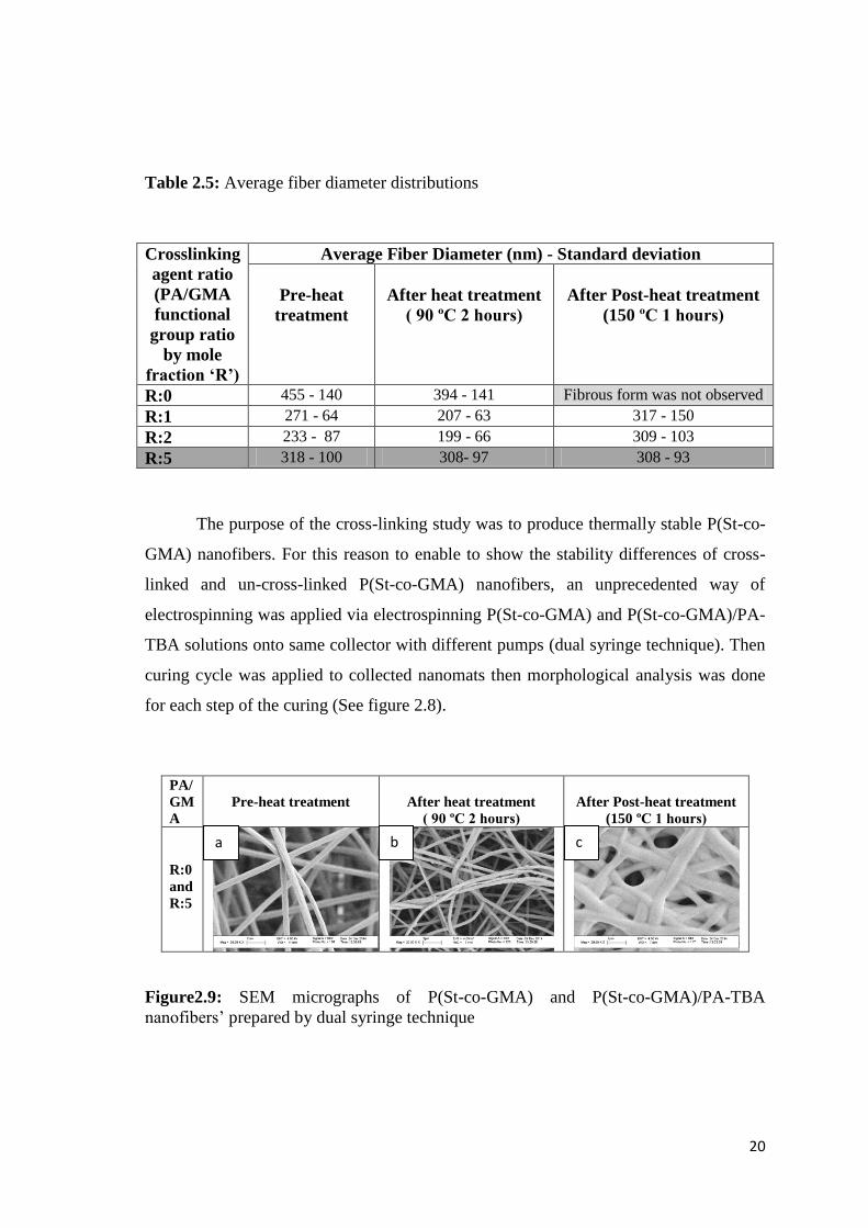
Table 2.5: Average fiber diameter distributions
Crosslinking
agent ratio
(PA/GMA
functional
group ratio
by mole
fraction ‘R’)
Average Fiber Diameter (nm) - Standard deviation
Pre-heat
treatment
After heat treatment
( 90 ºC 2 hours)
After Post-heat treatment
(150 ºC 1 hours)
R:0 455 - 140 394 - 141 Fibrous form was not observed
R:1 271 - 64 207 - 63 317 - 150
R:2 233 - 87 199 - 66 309 - 103
R:5 318 - 100 308- 97 308 - 93
The purpose of the cross-linking study was to produce thermally stable P(St-co-
GMA) nanofibers. For this reason to enable to show the stability differences of cross-
linked and un-cross-linked P(St-co-GMA) nanofibers, an unprecedented way of
electrospinning was applied via electrospinning P(St-co-GMA) and P(St-co-GMA)/PA-
TBA solutions onto same collector with different pumps (dual syringe technique). Then
curing cycle was applied to collected nanomats then morphological analysis was done
for each step of the curing (See figure 2.8).
PA/
GM
A
Pre-heat treatment
After heat treatment
( 90 ºC 2 hours)
After Post-heat treatment
(150 ºC 1 hours)
R:0
and
R:5
Figure2.9: SEM micrographs of P(St-co-GMA) and P(St-co-GMA)/PA-TBA
nanofibers’ prepared by dual syringe technique
a b c

21
SEM micrographs of the mixed nanofibers demonstrate that the un-crosslink-
able P(St-co-GMA) nanofibers could stand till their glass transition temperature (figure
2.9 b) however higher temperatures cause melting of the P(St-co-GMA) nanofibers.
Figure 2.9 c demonstrates that melted nanofibers covered the cross-linked P(St-co-
GMA)/PA-GMA nanofibers’ surface.
Mag. PA/GMA Ratio
R:1 R:5
5K
10K
20K
Figure 2.10: SEM micrographs of P(St-co-GMA)/PA-TBA nanofibers with PA/GMA
ratios R:1 and R:5 after immersion in DMF 72 h. (For neat samples please see figure
2.8)

22
Table 2.6: Average fiber diameter distributions before and after the swelling tests
PA/GMA Average Fiber Diameter (nm) - Standard deviation
Before Swelling test After Swelling test
R:1 271 - 64,20 648,36 -118,96
R:5 318,29 - 100,49 340,40 – 103,95
Figure 2.10 shows the SEM photos of the crosslinked P(St-co-GMA)/PA-TBA
nanofibers with PA/GMA mole ratio R:1 and R:5 after immersion in organic DMF
solvent for 72 h at room conditions. Comparison with the neat P(St-co-GMA)
nanofibers which are available in figure 2.8 d (R:1) and j(R:5). It can be seen that the
crosslinked nanofibers, which are with a PA/GMA ratio R:5, are rather unaffected
although the P(St-co-GMA) nanofibers have an aggressive solubility in DMF solvent.
The average fiber diameter analysis was done after the swelling tests (Table 2.6). The
average fiber diameter increased 140% for the R:1 case however for the R:5 case the
swelling of the fiber diameter’ were only 6%. It should be noted that crosslinked
PANGMA copolymers which are crosslinked by immersion to crosslinking agent
studied by Dai et al[11]. Dai also investigated the morphologies of crosslinked
PANGMA nanofibers after swelling in DMF solvent and reported as DMF cause
ribbon-like swelling with surface erosion. However our results shows that the harsh
environment of the DMF solvent has not affected the P(St-co-GMA)/PA-TBA
nanofibers. Consequently the crosslinked P(St-co-GMA)/PA-TBA nanofibers have
superior solvent resistance and therefore are very suitable for the applications in
aggressive solvent environments.

23
2.4 Concluding Remarks
In order to introduce stimuli-self-crosslinking ability to P(St-co-GMA) nanofibers
a chemical route was established by the addition of different ratios of crosslinking
agent PA and initiator TBA to the system. Electrospinning parameters were optimized
to enable time independent stimuli-self-crosslinkable nanofibers without rheological
constraints. As a result of thermal characterizations an increase of 30 ºC in glass
transition temperature was obtained. FT-IR analysis confirmed the chemical reaction
between the epoxide group of GMA and anhydride groups of PA by the initiation of
catalyst TBA. FT-IR analysis was supported with the swelling measurements and 98.3%
crosslinking ratio was acquired. Finally microscopic determination was done before and
after thermal process applied and morphological changes was not detected.
24
CHAPTER 3
DEMONSTRATION ON COMPOSITES
STRUCTURAL COMPOSITES HYBRIDIZED WITH EPOXY COMPATIBLE
IN-SITU CROSS-LINKED POLYMER NANOFIBROUS INTERLAYERS
3.1 Introduction
Polymer based nanofibers manufactured by electro-spinning are strong candidates
for interlaminar toughening of composite laminates. They can enhance mechanical
performance significantly in most of the composite applications without considerable
weight increase. Numerous studies in the literature [27],[28] present efforts to show
their potential. Recent works of our group,[1], [3], [6], [8] also highlight incorporation
of the nanofibers as the interlayers and associated delamination and transverse matrix-
cracking resistance of nano-interlayered laminates both through out of plane and in-
plane testing. The concept of toughening with nanofibrous interlayers begins with
designing/selecting a base polymer (see Table 3.1 for the variety of polymers introduced
as interlayers). The suitable choice of the nanofibers is the initial, but the vital part for
the successful practice. The relevant key factors to mark are solubility of the polymer,
and its electrospinnability in the form of fibers. Problem free electrospinning of a
polymer solution is typically expected to provide uniform fiber spinning without bead
formation. Compatibility with the matrix/resin of composite material and resin curing

25
conditions is also decisive. It is of paramount importance that the nanofiber material
should facilitate strong chemical bonding and interface compatibility. Moreover thermal
stability of the interlayer fibrous morphololgy (such as above glass transition and
melting temperature) is arguably essential and should be in compliance with the curing
cycle of matrix system as the distortions on the morphology may affect the failure
mechanisms and mechanical behavior. It is worth to underline the temperature
dependent behavior because typical high performance composite applications are of
high temperature cure systems. In the light of this issue, current work firstly shows the
effect of above Tg exposure on the nanofibrous interlayer morphologies such as the
curing temperature of carbon/epoxy prepreg system. Secondly, it offers a unique in-situ
crosslinking methodology where crosslinking of nanofibers takes place during the
consolidation of composite laminates before the Tg of nanofibers is exceeded. Lastly, it
shows the mechanical performance differences for un-crosslinked nanofiber interlayered
laminates and heat stimuli-self-crosslinked nanofiber interlayered laminates when they
both are cured above Tg of the nanofibers. The hypothesis is that stimuli-self-
crosslinking enables a homogenous crosslinking regime for the nanofibers while epoxy
matrix is cured as such better mechanical performance can be achieved. This
methodology is applicable and usable for nearly all acrylic and dominantly amorphous
engineering polymers. An example case is demonstrated where stimuli-self-crosslinked
P(St-co-GMA) nanofibers are added as interlayers to carbon/epoxy prepreg composites
for which the curing cycle demands 150°C or higher. Interlayered laminates are
subjected to three-point bending and mode II shear tests. Mechanical test outputs are
supported with cross-sectional and fracture surface microscopy analysis through
Scanning Electron Microscopy.

26
Table 3.1: Literature review for nanofiber interlayered studies
Author/Year Polymer
matrix/prepreg
Nano
reinforcement/
nanofiber
material
Experiment/
Test
Highlighted
investigation/results
J.S.Kim et
al[27]/ 1999
Epoxy
Polybenzimidazol
3-Point
Bending
Double
Torsion
Elastic modulus
% 27
KIC % 63
GIC % 263
Rubber Tension
Tear
Elastic modulus
% 988
Tensile Strength
% 33
Tear Strength
%91
Dzenis et
al[29] / 2009 Carbon/ epoxy Polybenzimidazol
DCB GIC % 15
ENF GIIC % 130
S.Sihn et al
[30]/ 2008 Carbon/ Epoxy
Polycarbonate
Tension
Micro crack
initiation % 8.4 ,
delamination % 8.1
L.Liu et al
[31]/ 2006
Glass fiber/
Epoxy
PA6
Tension
3-Point
Bending
Epoxy
609 < PA6 < TPU
Tensile Strength.
Epoxy
609 > PA6 > TPU
Tensile modulus
Epoxy 609
TPU
L.Liu et al
[32]/ 2008
Glass fiber/
Epoxy Epoxy 609 ENF GIIC % 9
S.H.Lee et al
[33]/2008
Carbon fiber/
Epoxy
Non-woven
carbon fabric
ENF
DCB
GIIC % 259
GIC % 28
S.H.Lee et al
[34]/2002
Carbon fiber/
Epoxy
Non-woven
carbon fabric ENF GIIC % 260
R. Palazzetti et
al[35]/ 2011
Epoxy/ Carbon
fiber(0/90)
Naylon 6,6
nanofiber mat
DCB
ENF
GIC %5
Absorbed Energy
%23
Absorbed Energy
%8.1
Maximum stress 6.5
Elif Özden et
al [1]/ 2010 Epoxy
P(St-co-GMA)
/EDA
3-Point
Bending
Flexural modulus
% 30
Flexural Strength
%23
P(St-co-GMA)
Flexural modulus
% 27
Flexural Strength
%16
PSt
Flexural modulus
% 27
Flexural Strength
%16
Kevin
Magniez et
al[36]/ 2011
Epoxy/ Carbon
fiber
poly(hydroxyether
(bisphenol A))
(phenoksi)
DCB
ENF
GIC %118
GIIC %30

27
J. Zhang et
al[37]/2010
Epoxy/ Carbon
fiber
Polyetherketon
cardo DCB
GIC-INI %60
GIC-PROP %81
J. Zhang et
al[38]/2012
Epoxy/ Carbon
fiber
poly(e-
caprolactone) DCB
GIC-INI %37
GIC-PROP %92
Daniel R.
Bortz et al[39]/
2011
Epoxy/ Carbon
fiber ±45
Helical Carbon
nanofiber DCB GIC %35
Masahiro Arai
et al [40]/2012
Epoxy/ Carbon
fiber
VGCF, VGCF-S,
MWNT-7
DCB
ENF
Mixed mode
Flexural
GIC 2.3 fold
GIIC 3.6 fold
Kaan Bilge et
al[6]/ 2012
Epoxy/ Carbon
fiber
P(St-co-GMA)
ENF GIIC % 55
Un-notched
Impact
Absorbed Energy %
8
Transversial
Tension
Transversal Tensile
Strength % 17
P(St-co-GMA)
/MWCNT
ENF GIIC % 70
Un-notched
Impact
Absorbed Energy
% 20
Transversial
Tension
Transversal Tensile
Strength % 27
Daniel R.
Bortz et al[41]/
2011
Epoxy
(amine cured)
Helical Carbon
nanofiber
3-Point
Bending
GIC %144
KIC %78
Tension-
Tension
Fatigue
Fatigue Life %365
S. Zainuddin
et al[42]/ 2010
Glass fiber/
Polyurethane/
epoxy sandwich
composite
Carbon nanofiber
(dispersed in
polyurethane
foam)
Semi-static
creep
Creep Strength
33%
Creep modulus 19%
Creep Fatigue
Test 400000 cycle
Christopher S
Grimmer et
al[43]/2008
Glass fiber/
Epoxy Carbon nanotube
Tension-
Tension
Fatigue
Long cycle fatigue
resistance
60% -250%
Yuanxin Zhou
et al[44]/ 2008
Epoxy/ Carbon
fiber (VDRTK) Carbon nanofiber
Tension-
Tension
Fatigue
Increase in Fatigue
life
3-Point
Bending
Flexural Strength
%22.3
Tension Tensile Strength
%11
C.
M.Manjunatha
et al [45]/2010
Glass fiber/
Epoxy
Micro rubber
particles (CTBN)
Tension
Fatigue Test
Fatigue Life inc. 3
fold
C.
M.Manjunatha
et al[46]/2010
Glass fiber/
Epoxy
CTBN and Silica
nano particles
Tension
Fatigue Test
Fatigue Life inc. 6-
10 fold
C. M.
Manjunathav
et al [47]/ 2010
Glass fiber/
Epoxy
Silica nano
particles
Tension
Fatigue Test
Fatigue Life inc. 3-4
fold
Mohammad A.
Rafiee et
al[48]/ 2010
Epoxy Grafene Tension
Fatigue Test
Crack Propagation
slowdown 25 fold

28
3.2 Experimental Procedure
3.2.1 Electro-spinning and Laminate Manufacturing
Self-Crosslinkable polymeric nanofibers were produced via electrospinning. The
production parameters were electrical bias, flow rate and tip to collector distance which
were set at 15 kV, 0.5 mL/h, 15 cm respectively (see figure 3.1). Pre-cut carbon/epoxy
prepreg layers were supplied by AKSA Akrilik Kimya San. A.Ş. which were placed
over the grounded collector. Then the polymer solution was electrospun directly onto
the prepreg surface. Despite depositon weight penalty due to the homogenously applied
nanofibrous interlayer is negligible, each as low as 0.2% of the hosting prepreg ply
weight.
Figure 3.1: Illustration of the electro-spinning over the prepreg plies
Note that, out-of-the freezer time and conditions of the prepared plies were kept
consistent throughout the study, whether being subject to electrospining (for reference
specimens and testing) or not. 3-point bending tests were done on composites produced
from the prepreg with ply thicknesses of 0.267 mm, whereas ENF tests were done on
composites produced from a prepreg of 0,067 mm nominal cured ply thickness. After
stacking the plies for intended laminates, each stack was put on a metallic mold along
with a release film and peel ply (see figure 3.2). Over the pile of plies another peel ply
sheet and breather layer were applied (see figure 3.3). Finally the whole lay-up was
vacuum bagged and kept under vacuum during the consolidation. The cure cycle was
selected primarily in accordance with the crosslinking temperature and glass transition

29
of the self-crosslink-able P(St-co-GMA)/PA-TBA nanofibers (as explained in Chapter
2) therefore, cure cycle was set as 2 hours at 90 ºC (lower than the Tg of P(St-co-GMA)
nanofibers) later 2 additional hours at 135 ºC. However P(St-co-GMA) nanofiber
interlayered structural composites cured with cycle 1 (see table 3.2)
Figure 3.2: Vacuum Bagging and Curing Process
Table 3.2: Cure cycles that subjected to structural composites
Heating Rate
(ºC/min)
Intermediate Step
(ºC)
Curing
Temperature
(ºC)
Polymer Type
Tg
Cycle 1 10 - 100 P(St-co-GMA) 100
Cycle 2 10 90 135 P(St-co-GMA) 100
P(St-co-GMA)/PA-TBA 128
3.2.2 Mechanical Testing
Zwick Roell Z100 Universal Testing Machine was used for mechanical testing.
Loading rates and machine accessories were set up in accordance with the testing types
and associated test standards.

30
3.2.2.1 3-Point Bending Tests
Flexural strength and modulus of (0/0/0) laminates were evaluated via three
point bending tests. Interlayered laminates were produced by deposition of interlayer
onto individual carbon/epoxy prepreg plies. Specimen preparation and testing
conditions were determined according to ASTM D790 standard. Applied load versus
crosshead displacement values were recorded and corresponding flexural strength (σf)
and flexural modulus (EB) values were calculated as follows:
where P is the maximum load, m is the slope of the tangent to the initial straight-line
portion of the load displacement curve and b, d, L are specimen width, thickness and
span length respectively.
Figure 3.3: Three-point bending test configurations and lamination sequences
3.2.2.2 End Notched Flexure (ENF) Test
Mode II critical strain energy release rate (GIIC) of the laminated composite
structures was determined by ENF test results. (0)48 uni-directional (UD) laminates
F

31
containing delamination at the mid-surface were tested under 3-point bending load
configuration according to ASTM D7905 (Standard Test Method for Determination of
the Mode II Interlaminar Fracture Toughness of Unidirectional Fiber-Reinforced
Polymer Matrix Composites). During the preparation of the laminates a non-adherent 30
µm thick film layer was placed to create the initial delamination for ENF testing
additionally electrospun nanofiber interlayer was applied only at the mid plane. Tests
were conducted with a constant displacement rate of 1mm/min and GIIC values were
calculated using direct beam theory [49].
Figure 3.4: ENF test configuration
3.2.3 Surface and Cross Sectional Characterization
Fracture surface and cross sectional analysis of the tested laminated composites
were carried out with a scanning electron microscope containing field emission gun
(SEM LEO 1530VP) using secondary electron detector at 2-5 kV after coating with Au-
Pd for better electrical conduction.

32
3.3 Results and Discussion
3.3.1 Optimization of Reinforcing Nanofibrous Layer Amount
The first step of mechanical characterization efforts was to investigate if the
areal density of electrospun nanofibrous interlayers (or thickness) was effective in the
flexural performance of the composite laminates. In order to do this, we have used our
conventional P(St-co-GMA) nanofibers without any crosslinking agent addition. The
composite laminates were cured according to curing receipt 1 (see table 3.2-cycle 1).
The interlayer depositon amount is varied by the polymer solution volume for a given
collector area. That is, the variable can also be introduced as areal density, gram per
square meter (GSM). GSM value calculated by the equation which is given below
where V is solution volume (ml) C is solution concentration (g polymer/ solution
volume) and A is electrospinning area (m2),
The electrospinning conditions were set as the same for all cases. With an
increase in the electrospinning solution volume from 0.25 to 1.5 ml, electrospinning was
done directly onto the 15×15 cm2 prepreg plies. Fabricated laminates have (0)3 stacking
sequence. Finally 3-point bending tests were done to investigate flexural properties of
laminates as a function of interlayer areal density (or thickness).
Table 3.3: 3-Point Bending test results for optimization
Polymer
Solution
Amount
ml
Volume
Neat 0,25 0,313 0,375 0,438 0,5 0,75 1,5
g/m2
GSM
Calculated
Neat
4,4
5,6
6,7
7,8
8,9
13,3
26,6
Flexural Strength
(MPa)
1255 1312 1371 1454 1404 1351 1251 1168

33
Figure 3.6 shows that the increasing amount of interleaving reinforcement
increased the flexural strength to maximum point where GSM was 6,7 corresponding to
polymer solution volume of 0,375 ml. Further increase of nanofibrous layer areal
density led to decrease on flexural strength although it was higher than the non-
interleaved strength upto a critical value. Beyond this critical limit, interlayer degraded
the flexural response that is attributed to the degradation of the effective adhesion
between the plies. These results indicate that there is an optimum for the best of
interlayers. Although interfacial compatibility between P(St-co-GMA) based polymeric
nanofibers and the epoxy resin is in effect [1, 3, 6-8], excessive use of them may result
in the mechanical performance of the laminates to deteriorate due to adverse effects on
interaction level in the inter-ply adhesion zone [37].
As a consequence the decision was reached to use the amount of 6,7 GSM
(0,375 ml) for further mechanical experiments.
Figure 3.5: Influence of reinforcement amount on flexural properties

34
3.3.2 Structural Compatibility of Stimuli-Self-Crosslinkable P(St-co-GMA)/PA-
TBA interlayers and Epoxy
Figure 3.6 show the SEM images of P(St-co-GMA) and stimuli-self-
crosslinkable P(St-co-GMA)/PA-TBA nanofibers electrospun onto the prepreg surfaces
after heating to 135 ºC. The magnified images show clearly the nanofibers’
morphologic changes by the influence of high curing temperature and interaction with
the epoxy.
Mag.
P(St-co-GMA) Nanofibers
onto prepreg surfaces
Stimuli-Self-Crosslinkable
Nanofiber onto prepreg surfaces
500
1K
5K
Figure 3.6: P(St-co-GMA) (left) and Stimuli-Self-Crosslinkable (right) Nanofibers onto
prepreg surfaces cured at 135 ºC (Magnifications: 500, 1K, 5K)

35
The left side SEM images at the figure 3.6 which belong to P(St-co-GMA)
nanofibers seem bead like polymeric islands transformed from the fibrous network.
When the image is further magnified over the epoxy poor region it is clear that fibrous
form/network changed and nanofibers are no longer distinctly exist,. However at the
right side of the figure 3.6 Stimuli-Self-Crosslinkable P(St-co-GMA)/PA-TBA
nanofibers can be seen and it is evident that fibrous form and their integrity were not
influenced by above Tg heating scheme. It is important to confirm that epoxy and the
stimuli-self-crosslinkable nanofibers are also structurally compatible (see the magnified
images). Randomly oriented nanofibers at the surface of the prepreg plies can easily be
seen despite being after above Tg heat treatment.
Nanofibrous mat over the prepreg layers
After the electrospinning
Nanofibrous mat over the prepreg layers
After curing at the 135 ºC
Figure 3.7: Nanofibrous mat over prepreg layers (P(St-co-GMA) nanofibers at left,
Stimuli-self-crosslinkable P(St-co-GMA)/PA-TBA nanofibers at right)
To macroscopically investigate that interaction with nanofibrous layers and
epoxy prepreg surfaces at the center of the prepreg plies a nanofiber rich area was
deliberately created to prevent the completely wetting of the fibers at that area (Figure
3.7). Consequently excessive amount of stimuli-self-crosslinkable nanofibers at the
center could not get wet completely and also maintain the fibrous form. This is also a
brute force representation of the effect of excessively thick nanofibrous interlayer
mentioned in the previous section. However the P(St-co-GMA) nanofibers were
transformed into a polymeric coat at the surface of the prepreg, which apparently wetted
thoroughly by the epoxy.

36
3.3.3 Flexural Performance by 3-Point-Bending Tests
Results of 3-point bending tests of laminates interlayered with stimuli-self-
crosslinkable P(St-co-GMA), P(St-co-GMA) nanofibrous mats and also not interlayered
reference neat composite laminates, suggest that the addition of the P(St-co-GMA)
cause decrement in flexural properties, however introducing stimuli self-crosslinkable
P(St-co-GMA) nanofibers let to increase in both flexural strength and modulus of the
samples at high curing temperatures.
Figure 3.8: Representative 3-Point Bending test curves for (0)3 laminates
As shown in the figure 3.8 the addition of the P(St-co-GMA)/PA-TBA
nanofibers to the laminated composites with an increasing PA/GMA ratio led to
increase in flexural properties in the same manner up to 15%, while P(St-co-GMA)
nanofiber introduced laminates’ flexural properties diminish compared to the neat
laminates when cured at above Tg temperatures. However the earlier works of the group
revealed that P(St-co-GMA) nanofiber addition of the system at lower curing

37
temperatures than the nanofiber’ glass transition point led to an increase at the flexural
properties[1, 6-8].
Table 3.4: 3-Point Bending test results
PA/GMA
ratio of
interlayer
Flexural Strength
(MPa)
Neat 1254
R:0 1340
R:1 1340
R:2 1368
R:5 1452
It can be expected that two distinct failure mechanisms, transverse matrix
cracking and/or delamination cause to failure in (0)3 laminates. It is known that the co-
existence of these two mechanisms enable the creation of pure shear conditions via 3-
point bending tests [6]. The representative failure modes are given in the figure 3.9. The
flexural strength increase reported via 3-point bending tests characterized both
resistance to delamination and matrix toughening by the addition of the nanofibrous
interlayers. Pure shear conditions are also observed by ENF tests done[30].
Figure 3.9: Representative cross-sectional view for fractured 3-point bending
specimens both include transverse matrix cracking (1) and delamination (2)

38
3.3.4 Mode II Strain Energy release rate by ENF Tests
Heat Stimuli-Self-Crosslinked interlayer at the pre-crack tip increased GIIC by
80% whereas the interlayers of P(St-co-GMA) nanofibers decreased GIIC by 40% since
the curing temperature of the composites was higher than their glass transition
temperature (135 C for 2 hours). It should be noted that the earlier works of the group
showed that for curing cycles at lower temperature for longer time (100 C for 8 hours)
P(St-co-GMA) nanofibers did not transform and were as successful leading to increase
at mode II strain energy release rate by about 55 %.
Figure 3.10: Representative ENF test curves for (0)48 laminates

39
Mag.
P(St-co-GMA)
nanofiber interlayered ENF samples
Stimuli-Self-Crosslinked
nanofiber interlayered ENF samples
2K
5K
10K
Figure 3.11: Fracture surfaces of P(St-co-GMA) and Stimuli-Self crosslinked
Nanofiber interlayered interface. Zoomed in views for encircled areas for each
interlayer. (Magnifications: 500, 1K, 5K)
Figure 3.12: Fracture surfaces of neat interface
c
a b
d
e f
40
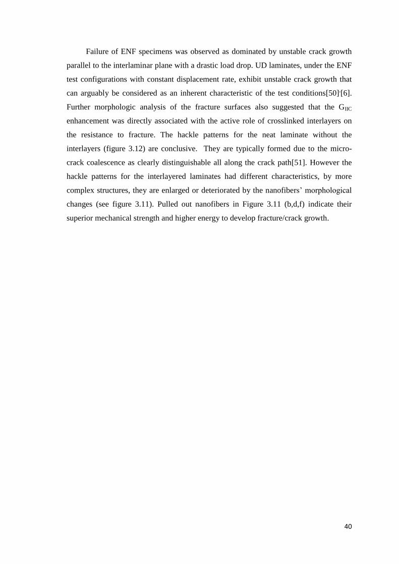
Failure of ENF specimens was observed as dominated by unstable crack growth
parallel to the interlaminar plane with a drastic load drop. UD laminates, under the ENF
test configurations with constant displacement rate, exhibit unstable crack growth that
can arguably be considered as an inherent characteristic of the test conditions[50],[6].
Further morphologic analysis of the fracture surfaces also suggested that the GIIC
enhancement was directly associated with the active role of crosslinked interlayers on
the resistance to fracture. The hackle patterns for the neat laminate without the
interlayers (figure 3.12) are conclusive. They are typically formed due to the micro-
crack coalescence as clearly distinguishable all along the crack path[51]. However the
hackle patterns for the interlayered laminates had different characteristics, by more
complex structures, they are enlarged or deteriorated by the nanofibers’ morphological
changes (see figure 3.11). Pulled out nanofibers in Figure 3.11 (b,d,f) indicate their
superior mechanical strength and higher energy to develop fracture/crack growth.
41
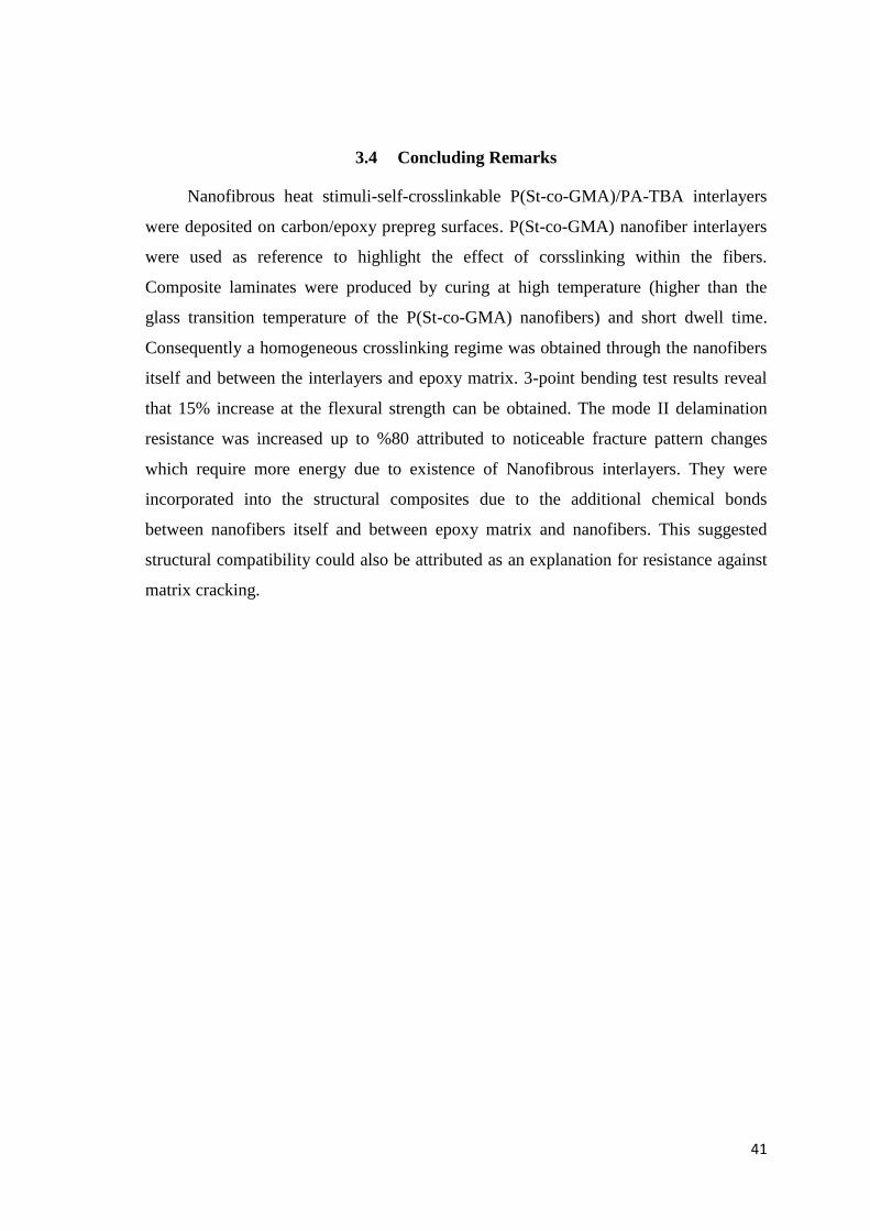
3.4 Concluding Remarks
Nanofibrous heat stimuli-self-crosslinkable P(St-co-GMA)/PA-TBA interlayers
were deposited on carbon/epoxy prepreg surfaces. P(St-co-GMA) nanofiber interlayers
were used as reference to highlight the effect of corsslinking within the fibers.
Composite laminates were produced by curing at high temperature (higher than the
glass transition temperature of the P(St-co-GMA) nanofibers) and short dwell time.
Consequently a homogeneous crosslinking regime was obtained through the nanofibers
itself and between the interlayers and epoxy matrix. 3-point bending test results reveal
that 15% increase at the flexural strength can be obtained. The mode II delamination
resistance was increased up to %80 attributed to noticeable fracture pattern changes
which require more energy due to existence of Nanofibrous interlayers. They were
incorporated into the structural composites due to the additional chemical bonds
between nanofibers itself and between epoxy matrix and nanofibers. This suggested
structural compatibility could also be attributed as an explanation for resistance against
matrix cracking.

42
REFERENCES
[1] Ozden E, Menceloglu YZ, Papila M. Engineering chemistry of electrospun
nanofibers and interfaces in nanocomposites for superior mechanical properties. ACS
applied materials & interfaces 2010;2:1788-93.
[2] Huang Z-M, Zhang Y-Z, Kotaki M, Ramakrishna S. A review on polymer
nanofibers by electrospinning and their applications in nanocomposites. Composites
science and technology 2003;63:2223-53.
[3 Özden-Yenigün E, Menceloğlu YZ, Papila M. M CNTs/P (St-co-GMA) composite
nanofibers of engineered interface chemistry for epoxy matrix nanocomposites. ACS
applied materials & interfaces 2012;4:777-84.
[4] Zong X, Kim K, Fang D, Ran S, Hsiao BS, Chu B. Structure and process
relationship of electrospun bioabsorbable nanofiber membranes. Polymer
2002;43:4403-12.
[5] Zucchelli A, Focarete ML, Gualandi C, Ramakrishna S. Electrospun nanofibers for
enhancing structural performance of composite materials. Polymers for Advanced
Technologies 2011;22:339-49.
[6] Bilge K, Ozden-Yenigun E, Simsek E, Menceloglu Y, Papila M. Structural
composites hybridized with epoxy compatible polymer/MWCNT nanofibrous
interlayers. Composites Science and Technology 2012;72:1639-45.
[7 Bilge K, Özden Yenigün E, Şimşek E, Menceloğlu YZ, Papila M. Strength of hybrid
composites reinforced with surface modified polymer/MWCNTs nano-composite
interlayers. 2011.
[8] Bilge K, Venkataraman S, Menceloglu Y, Papila M. Global and local nanofibrous
interlayer toughened composites for higher in-plane strength. Composites Part A:
Applied Science and Manufacturing 2014;58:73-6.
[9] Zheng J, He A, Li J, Xu J, Han CC. Studies on the controlled morphology and
wettability of polystyrene surfaces by electrospinning or electrospraying. Polymer
2006;47:7095-102.
[10 Yördem O, Papila M, Menceloğlu YZ. Effects of electrospinning parameters on
polyacrylonitrile nanofiber diameter: An investigation by response surface
methodology. Materials & design 2008;29:34-44.
[11] Dai T, Ebert K. Electrospinning of solvent-resistant nanofibers based on
poly(acrylonitrile-co-glycidyl methacrylate). Journal of Applied Polymer Science
2012;126:136-42.
[12] Peresin MS, Vesterinen AH, Habibi Y, Johansson LS, Pawlak JJ, Nevzorov AA, et
al. Crosslinked PVA nanofibers reinforced with cellulose nanocrystals: Water

43
interactions and thermomechanical properties. Journal of Applied Polymer Science
2014;131.
[13] Gupta P, Trenor SR, Long TE, Wilkes GL. In situ photo-cross-linking of cinnamate
functionalized poly (methyl methacrylate-co-2-hydroxyethyl acrylate) fibers during
electrospinning. Macromolecules 2004;37:9211-8.
[14] Kim SH, Kim S-H, Nair S, Moore E. Reactive electrospinning of cross-linked poly
(2-hydroxyethyl methacrylate) nanofibers and elastic properties of individual hydrogel
nanofibers in aqueous solutions. Macromolecules 2005;38:3719-23.
[15] Ji Y, Ghosh K, Li B, Sokolov JC, Clark RA, Rafailovich MH. Dual‐Syringe
Reactive Electrospinning of Cross‐Linked Hyaluronic Acid Hydrogel Nanofibers for
Tissue Engineering Applications. Macromolecular bioscience 2006;6:811-7.
[16] Stone SA, Gosavi P, Athauda TJ, Ozer RR. In situ citric acid crosslinking of
alginate/polyvinyl alcohol electrospun nanofibers. Materials Letters 2013;112:32-5.
[17] Liu H, Zhen M, Wu R. Ionic‐Strength‐and pH‐Responsive Poly [acrylamide‐co‐(maleic acid)] Hydrogel Nanofibers. Macromolecular Chemistry and Physics
2007;208:874-80.
[18] Tang C, Saquing CD, Harding JR, Khan SA. In SituCross-Linking of Electrospun
Poly(vinyl alcohol) Nanofibers. Macromolecules 2010;43:630-7.
[19 Matějka L, Lövy J, Pokorný S, Bouchal K, Dušek K. Curing epoxy resins with
anhydrides. Model reactions and reaction mechanism. Journal of Polymer Science:
Polymer Chemistry Edition 1983;21:2873-85.
[20] Fischer RF. Polyesters from Epoxides and Anhydrides. JOURNAL OF POLYMER
SCIENCE 1960;44:155-72.
[21] Antoon MK, Koenig JL. Crosslinking mechanism of an anhydride-cured epoxy
resin as studied by fourier transform infrared spectroscopy. Journal of Polymer Science:
Polymer Chemistry Edition 1981;19:549-70.
[22] Tillet G, Boutevin B, Ameduri B. Chemical reactions of polymer crosslinking and
post-crosslinking at room and medium temperature. Progress in Polymer Science
2011;36:191-217.
[23] Kim K-J, Lee S-B, Han N-W. Kinetics of crosslinking reaction of PVA membrane
with glutaraldehyde. Korean Journal of Chemical Engineering 1994;11:41-7.
[24] Guerrero P, De la Caba K, Valea A, Corcuera M, Mondragon I. Influence of cure
schedule and stoichiometry on the dynamic mechanical behaviour of tetrafunctional
epoxy resins cured with anhydrides. Polymer 1996;37:2195-200.
[25] Luo X, Zheng S, Ma D. Mechanical Relaxation and Intermolecular Interaction in
Epoxy Resins/ (Poly Ethylene Oxide) Blends Cured with Phthalic Anhydride. Chinese
Journel of Polymer Science 1995;13:144-53.
44
[26 Romão BMV, Diniz MF, Azevedo MFP, Lourenço VL, Pardini LC, Dutra RCL, et
al. Characterization of the Curing Agents Used in Epoxy Resins with TG/FT-IR
Technique. Polímeros: Ciência e Tecnologia 2006;16:94-8.
[27] Kim Js, Reneker DH. Mechanical properties of composites using ultrafine
electrospun fibers. Polymer composites 1999;20:124-31.
[28] Tsotsis TK. Interlayer toughening of composite materials. Polymer Composites
2009;30:70-86.
[29] Dzenis YA, Reneker DH. Delamination resistant composites prepared by small
diameter fiber reinforcement at ply interfaces. Google Patents; 2001.
[30] Sihn S, Kim RY, Huh W, Lee K-H, Roy AK. Improvement of damage resistance in
laminated composites with electrospun nano-interlayers. Composites Science and
Technology 2008;68:673-83.
[31] Liu L, Huang Z-M, He C, Han X. Mechanical performance of laminated
composites incorporated with nanofibrous membranes. Materials Science and
Engineering: A 2006;435:309-17.
[32] Liu L, Huang ZM, Xu GY, Liang YM, Dong GH. Mode II interlaminar
delamination of composite laminates incorporating with polymer ultrathin fibers.
Polymer Composites 2008;29:285-92.
[33] Lee S-H, Lee J-H, Cheong S-K, Noguchi H. A toughening and strengthening
technique of hybrid composites with non-woven tissue. journal of materials processing
technology 2008;207:21-9.
[34] Lee S-H, Noguchi H, Kim Y-B, Cheong S-K. Effect of interleaved non-woven
carbon tissue on interlaminar fracture toughness of laminated composites: Part I–Mode
II. Journal of composite materials 2002;36:2153-68.
[35] Palazzetti R, Zucchelli A, Gualandi C, Focarete M, Donati L, Minak G, et al.
Influence of electrospun Nylon 6, 6 nanofibrous mats on the interlaminar properties of
Gr–epoxy composite laminates. Composite Structures 2012;94:571-9.
[36] Magniez K, Chaffraix T, Fox B. Toughening of a carbon-fibre composite using
electrospun poly (hydroxyether of bisphenol a) nanofibrous membranes through inverse
phase separation and inter-domain etherification. Materials 2011;4:1967-84.
[37] Zhang J, Lin T, Wang X. Electrospun nanofibre toughened carbon/epoxy
composites: Effects of polyetherketone cardo (PEK-C) nanofibre diameter and
interlayer thickness. Composites science and technology 2010;70:1660-6.
[38] Zhang J, Yang T, Lin T, Wang CH. Phase morphology of nanofibre interlayers:
Critical factor for toughening carbon/epoxy composites. Composites science and
technology 2012;72:256-62.

45
[39] Bortz DR, Merino C, Martin-Gullon I. Mechanical characterization of hierarchical
carbon fiber/nanofiber composite laminates. Composites Part A: Applied Science and
Manufacturing 2011;42:1584-91.
[40] Arai M, Sasaki T, Hirota S, Ito H, Hu N, Quaresimin M. Mixed modes interlaminar
fracture toughness of CFRP laminates toughened with CNF interlayer. Acta Mechanica
Solida Sinica 2012;25:321-30.
[41] Bortz DR, Merino C, Martin-Gullon I. Carbon nanofibers enhance the fracture
toughness and fatigue performance of a structural epoxy system. Composites Science
and Technology 2011;71:31-8.
[42] Zainuddin S, Mahfuz H, Jeelani S. Enhancing fatigue performance of sandwich
composites with nanophased core. Journal of Nanomaterials 2010;2010:11.
[43] Grimmer CS, Dharan C. High-cycle fatigue of hybrid carbon nanotube/glass
fiber/polymer composites. Journal of Materials Science 2008;43:4487-92.
[44] Zhou Y, Pervin F, Jeelani S, Mallick P. Improvement in mechanical properties of
carbon fabric–epoxy composite using carbon nanofibers. Journal of materials
processing technology 2008;198:445-53.
[45] Manjunatha C, Taylor A, Kinloch A, Sprenger S. The tensile fatigue behaviour of a
GFRP composite with rubber particle modified epoxy matrix. Journal of reinforced
Plastics and Composites 2009.
[46] Manjunatha C, Sprenger S, Taylor A, Kinloch A. The tensile fatigue behavior of a
glass-fiber reinforced plastic composite using a hybrid-toughened epoxy matrix. Journal
of composite materials 2010;44:2095-109.
[47] Manjunatha C, Taylor A, Kinloch A, Sprenger S. The tensile fatigue behaviour of a
silica nanoparticle-modified glass fibre reinforced epoxy composite. Composites
Science and Technology 2010;70:193-9.
[48] Rafiee MA, Rafiee J, Srivastava I, Wang Z, Song H, Yu ZZ, et al. Fracture and
fatigue in graphene nanocomposites. small 2010;6:179-83.
[49] Albertsen H, Ivens J, Peters P, Wevers M, Verpoest I. Interlaminar fracture
toughness of CFRP influenced by fibre surface treatment: Part 1. Experimental results.
Composites Science and Technology 1995;54:133-45.
[50] Seyhan AT, Tanoglu M, Schulte K. Mode I and mode II fracture toughness of E-
glass non-crimp fabric/carbon nanotube (CNT) modified polymer based composites.
Engineering Fracture Mechanics 2008;75:5151-62.
[51] Stevanovic D, Kalyanasundaram S, Lowe A, Jar P-Y. Mode I and mode II
delamination properties of glass/vinyl-ester composite toughened by particulate
modified interlayers. Composites science and technology 2003;63:1949-64.