High Strain Rate Deformation Modeling of a Polymer Matrix ...
38
NASA / TMm1998-206969 High Strain Rate Deformation Modeling of a Polymer Matrix Composite Part ImMatrix Constitutive Equations Robert K. Goldberg Lewis Research Center, Cleveland, Ohio Donald C. Stouffer University of Cincinnati, Cincinnati, Ohio National Aeronautics and Space Administration Lewis Research Center August 1998
Transcript of High Strain Rate Deformation Modeling of a Polymer Matrix ...

NASA / TMm1998-206969
High Strain Rate Deformation Modeling
of a Polymer Matrix CompositePart ImMatrix Constitutive Equations
Robert K. Goldberg
Lewis Research Center, Cleveland, Ohio
Donald C. Stouffer
University of Cincinnati, Cincinnati, Ohio
National Aeronautics and
Space Administration
Lewis Research Center
August 1998
Acknowledgments
The authors would like to acknowledge Fiberite, Inc. for providing the material used for the experimental tests
along with information and data on the material. The authors would also like to acknowledge
Cincinnati Testing Laboratories, Inc., for conducting the low strain r._te tensile experiments presented in this report.
The University of Dayton Research Institute Impact Physics Lab is also acknowledged for conducting
the high strain rate experiments discu.,_sed in this study.
Trade names or manufacturers' names are used in this report for
identification only. This usage does not constitute an official
endorsement, either expressed or implied, by the National
Aeronautics and Space AdmiJristration.
NASA Center for Aerospace Information7121 Standard Drive
Hanover, MD 21076Price Code: A03
Available from
National Technical Information Service
5287 Port Royal Road
Springfield, VA 22100Price Code: A03

High Strain Rate Deformation Modeling of a Polymer Matrix
Composite: Part I-Matrix Constitutive Equations
Robert K. Goldberg
National Aeronautics and Space AdministrationLewis Research Center
Cleveland, Ohio 44135
and
Donald C. Stouffer
University of Cincinnati
Cincinnati, Ohio 45221
SUMMARY
Recently applications have exposed polymer matrix composite materials to very high
strain rate loading conditions, requiring an ability to understand and predict the material
behavior under these extreme conditions. In this first paper of a two part report,
background information is presented, along with the constitutive equations which will be
used to model the rate dependent nonlinear deformation response of the polymer matrix.
Strain rate dependent inelastic constitutive models which were originally developed to
model the viscoplastic deformation of metals have been adapted to model the nonlinear
viscoelastic deformation of polymers. The modified equations were correlated by
analyzing the tensile/compressive response of both 977-2 toughened epoxy matrix and
PEEK thermoplastic matrix over a variety of strain rates. For the cases examined, the
modified constitutive equations appear to do an adequate job of modeling the polymer
deformation response. A second follow-up paper will describe the implementation of the
polymer deformation model into a composite micromechanical model, to allow for the
modeling of the nonlinear, rate dependent deformation response of polymer matrix
composites.
LIST OF SYMBOLS
DO
E
n
q
Sijt
At
Z
Zo
material constant representing maximum inelastic strain rate
elastic modulus of material
material constant representing rate dependence of material
material constant representing hardening rate of material
deviatoric stress componentcurrent time
current time increment
scalar state variable
material constant representing initial isotropic hardness of material
NASA/TM--1998-206969 1

ZlE
E I
E_ij
_x
_ij
U
Us
material constant representing value of scalar state variable at saturation
uniaxial strain
uniaxial inelastic strain
inelastic strain component
effective inelastic strain
inelastic strain at saturation
constant total applied strain rate
uniaxial back stress
back stress component
material constant representing value of back stress at saturation
uniaxial stress
value of stress at saturation
quantities with dots above them represent rates
INTRODUCTION
NASA Lewis Research Center has an ongoing research program to develop new
technologies to improve aircraft engine fan containment systems. The program contains a
feasibility study to replace metallic containment systems with polymer matrix composite
hardwall containment systems. In such an application, the composite would be loaded at
strain rates up to several hundred per second. In designi:ag a polymer matrix composite
containment system, the ability to correctly model the c¢,nstitutive and failure behavior of
the composite under the high rate loading conditions present is of critical importance.
Experimental techniques to characterize the behavior of polymer matrix composites
under low strain rate loading conditions have been well established for many years.
Furthermore, numerous analytical methods have been de veloped to model the constitutive
and failure behavior of composites under quasi-static lo_ds. However, the analytical
methods required to characterize and model the constitutive and failure behavior of
polymer matrix composites under high strain rates are not nearly as well developed as is
the case for materials under quasi-static loads. Furtherrr, ore, the effects of strain rate on
the material properties and response is still an area of aczive investigation.
This paper, the first of a two part report, describes the adaptation of constitutive
equations designed to model the viscoplastic deformation response of metals to the
problem of modeling the inelastic, strain rate dependent response of a polymer. First,
some general background, including a review of the literature, will be presented. In the
background section of this report, previous investigation s into characterizing and
modeling the rate dependent response of polymers and polymer matrix composites will be
described. Specifically, experimental tests designed to determine the rate dependence of
the properties and response of a polymer matrix composite will be described. In addition,
analytical methods which have been developed to represent the rate dependent response
of both bulk polymers and polymer matrix composites will be discussed.
NASA/TM-- 1998-206969 2
After the background section, the strain rate dependent, inelastic constitutive equations
which were utilized to model the polymer matrix will be discussed. For the constitutive
equations, techniques which were originally designed to represent the rate-dependent,
viscoplastic response of metals have been adapted and modified to model the inelastic
response of a polymer. A description of these methods, and how they were modified to
analyze the tensile/compressive response of a polymer, will be given. Furthermore, the
analytical procedure utilized to obtain material constants for two representative materials,
Fiberite 977-2 toughened epoxy and PEEK thermoplastic, will be described. The
experimental procedures which were utilized to obtain the material data will also be
presented. The computational approach used to implement the equations will be
discussed, and the stress-strain curves obtained by using the developed models will be
presented. Conclusions on which of the presented constitutive models will be utilized in
the remainder of the project will be given.
BACKGROUND
Strain Rate Effects on Material Properties
Several experimental studies have been performed with the goal of determining the
effects of strain rate on the material properties and response of polymer matrix composite
systems at high strain rate conditions. One such method of performing such studies
involves using the split Hopkinson bar technique, which was utilized by researchers such
as Harding and Welsh [1], Staab and Gilat [2] and Choe, Finch and Vinson [3]. The
technique has been extensively utilized in characterizing metals at high strain rates [4].
The basic technique involves propelling a striker bar into a pressure bar. The pressure bar
then transmits a compression stress wave which propagates through the specimen,
sandwiched between the pressure bar and a transmission bar. Gages on the pressure and
transmission bars are then utilized to compute the force and displacement in the specimen
based on the wave propagation profiles.
Harding and Welsh [1] created a modified split Hopkinson bar apparatus to allow for
the tensile testing of unidirectional graphite/epoxy composites at high strain rates. Tests
were conducted at strain rates ranging from 5E-04/sec to 450/see on composites with a
[0] fiber orientation. The stress-strain curves obtained were nearly linear until failure,
and there was minimal change in the elastic modulus and fracture strength with strain
rate. Since the response of a [0] composite is primarily fiber dominated, these results
indicate that the graphite fibers have minimal strain rate dependence. Harding also
conducted split Hopkinson bar tests on glass/epoxy and glass/polyester woven composites
loaded with a punch loading condition [5]. For both types of materials tested, the study
found that increasing the punch speed resulted in an increase in the maximum punch load
present in the specimen, as well as an increase in the shear strength of the specimen.
NASA/TM--1998-206969 3

Staab and Gilat [2] conducted tensile split Hopkinson bar tests and static tests on
glass/epoxy composites over a strain rate range from 1E-04/sec to approximately 1000
/sec. Laminates with fiber orientations ranging from [-+15]s to [-+75]s were examined. For
each of the laminate orientations considered, increasing the strain rate increased the initial
modulus, maximum stress and failure strain. The difference between the static results
and the high strain rate results increased significantly as the laminate orientation angle
decreased. In compressive split Hopkinson bar tests that Choe, Finch and Vinson [5]
conducted, the ultimate stress and modulus were found to increase with strain rate for
unidirectional graphite/epoxy specimens. The ultimate stress also increased with strain
rate for quasi-isotropic graphite/epoxy specimens.
Another type of test technique utilized to determine the response of polymer matrix
composites at high strain rates involves subjecting the composite to explosive pressure
pulse loadings. Such methods were utilized by Daniel, Hsaio and Cordes [6], Daniel,
Hamilton and LaBedz [7] and A1-Salehi, A1-Hassani anti Hinton [8]. Daniel, et. al. [6,7]
utilized an expanding ring, where a thin composite ring is subject to an explosive pulse
loading. In combination with static tests, the effects of strain rate on the longitudinal,
transverse and shear properties of a unidirectional graphite/epoxy composite system were
determined. The experiments were conducted using strain rates ranging from 1E-04/sec
to 500/sec. In the longitudinal direction, the modulus increased slightly, but the strengthand failure strain showed almost no variation as the strain rate was increased. In the
transverse direction, on the other hand, the modulus and strength increased sharply, and
the failure strain showed a slight increase with higher strain rates. When the shear
properties were examined, the modulus increased significantly, the strength increased a
moderate amount, and the failure strain showed a slight decrease with increasing strain
rate. Since the longitudinal properties of a unidirectional composite system are fiber
dominated, the results obtained indicate that for a graphite/epoxy composite the
properties of the carbon fiber do not vary significantly with strain rate (similar to what
was found by Harding and Welsh [1]). However, since the transverse and shear
properties are matrix dominated, the results indicate that the behavior of the epoxy matrix
does vary significantly with strain rate, and drives the ra,e dependence of the composite.
Utilizing similar testing techniques, A1-Salehi, et. al. [8] found that for a filament wound
glass-epoxy tube, the burst strength and failure strain increased, while the elastic modulus
displayed minimal variation, with higher strain rates.
The correlation between the strain rate dependence of the composite and the rate
dependence of the matrix, particularly at high strain rate:q for graphite/epoxy composites
was further established by Groves, et. al [9]. In compression tests on a graphite/epoxy
composite, the compression strength was found to increase with strain rate, with the
increase being most pronounced at higher strain rates (on the order of 100-1000/sec). To
attempt to explain this behavior, tensile and compressiw; stress-strain curves were
generated for the epoxy matrix over a variety of strain rates. For both tensile and
compressive loadings, the modulus was found to increase with strain rate, with significant
increases occurring at strain rates above 10/sec. Furthmmore, the compressive strength
was found to increase steadily with strain rate, while the tensile strength was found to
NASA/TM--1998-206969 4

increase dramatically at strain rates above 10/sec. The results from these tests confirmed
that strain rate had a significant effect on the properties of the epoxy matrix in a
graphite/epoxy system.
The overall result from these experimental studies is that while the details may vary
based on the type of fiber and fiber orientation angle used, the material properties and
response of polymer matrix composites do vary with strain rate, particularly at high strain
rate conditions. In particular, for graphite/epoxy systems, the strain rate dependence
appears to be driven by the strain rate dependence of the polymer matrix, indicating that
in modeling composites of this type, capturing the rate dependent response of the polymer
matrix is of critical importance.
Polymer Constitutive Modeling
Polymers have long been known to have a rate-dependent constitutive response.
Traditionally, for very small strain response, linear viscoelastic techniques have been
used to model the rate dependent behavior on a phenomelogical level [10]. In linear
viscoelastic models, combinations of springs and dashpots in series and parallel may be
used to capture the rate dependent behavior. When the strains are large enough that the
response is no longer linear, nonlinear viscoelastic models have been developed. For
example, in a model developed by Cessna and Sternstein [11], nonlinear dashpots are
incorporated into the constitutive model. Empirical equations are also used to capture the
rate dependent response, in which the yield stress is scaled as a function of strain rate
[12].
A more sophisticated approach to polymer constitutive modeling takes a molecular
approach. In this approach [13], it is assumed that the deformation of a polymer is due to
the motion of molecular chains over potential energy barriers. The molecular flow is due
to applied stress, and the internal viscosity is assumed to decrease with applied stress.
The yield stress (the point where permanent deformation begins) is defined as the point
where the internal viscosity decreases to the point where the applied strain rate is equal to
the plastic strain rate. Internal stresses can also be defined [13,14], which represent the
resistance to molecular flow which tends to drive the material back towards its original
configuration. Another approach to polymer deformation assumes that the deformation is
due to the unwinding of molecular kinks [15]. In both approaches, constitutive models
have been developed [13-17] in which the deformation response is considered to be a
• function of parameters such as activation energy, activation volume, molecular radius,
molecular angle of rotation, and thermal constants. Furthermore, the deformation is
assumed to be a function of state variables which represent the resistance to molecular
flow caused by a variety of mechanisms. The state variable values evolve with stress,
inelastic strain and inelastic strain rate.
An alternative approach to the constitutive modeling of polymers is to utilize, either
directly or with some modifications, viscoplastic constitutive equations which have been
developed for metals. For example, Bordonaro [18] modified the Viscoplasticity Theory
NASA/TM--1998-206969 5

Based on Overstress developed by Krempl [19]. In Bordonaro's model, the original
theory was modified to attempt to account for phenomerta encountered in the deformation
of polymers that are not present in metals. For example, polymers behave differently
from metals under conditions such as creep, relaxation, and unloading. Other authors,
such as Valisetty and Teply [20] and Zhang and Moore [21], utilized techniques
developed to model the deformation of metals directly with no modification. However,
they primarily limited their study to analyzing the uniaxial tensile response of polymers
and did not consider phenomena such as unloading, creep or relaxation.
The conclusion to be drawn from the work discussed above is that it is possible to
analyze the rate dependent response of polymers by simulating the physical deformation
mechanisms. Furthermore, the physical deformation mechanisms can be modeled by the
use of state variables. This approach is very similar to what is used in viscoplastic
constitutive equations which are utilized for metals. The work completed to date
indicates that modeling techniques developed for metals can be adapted for use with
polymers. However, appropriate modifications must be made to the equations and
consideration must be given to the range of applicability of the model.
Composite Constitutive Modeling
Previous efforts to simulate the rate dependent response of polymer matrix composites
at high strain rates have utilized both macroscopic and micromechanics approaches. In
the macroscopic approach, the composite material is modeled as an anisotropic,
homogenous material, without any attention being paid lo the individual constituents.
For example, Weeks and Sun [22] developed a macroscopic, rate-dependent constitutive
model to analyze the nonlinear high strain rate response of thick composite laminates.
Building upon previous work conducted by Yoon and Sun [23] and Gates and Sun [24],
the inelastic behavior of a carbon fiber reinforced thermoplastic was simulated through
the use of a quadratic plastic potential function. A scaling function was defined to model
the variation of the response due to varying fiber orientation of a single ply. The finite
element method was utilized to analyze a composite lan_inate, where a layer of elements
was used to simulate a single ply. The rate dependence 3f the deformation response was
captured by varying the material properties as a function of strain rate. This technique
was later modified by Thiruppukuzhi and Sun [25] in order to directly incorporate the rate
dependence of the material response into the constitutive model. A similar type of
approach was utilized by Espinosa, Lu, Dwivedi and Zavattieri [26]. However, the finite
element procedures utilized were specifically reformulated to account for the dynamic,
large deformation response often seen in high strain rate impact problems.
Other approaches have been used to model the high strain rate response of polymer
matrix composites on the macroscopic scale. For instan:e, O'Donoghue, et. al. [27]
assumed an orthotropic, linear elastic deformation response, but reformulated the
constitutive equations to separate out the hydrostatic and deviatoric stresses. This stress
separation facilitated implementation of the technique into a transient dynamic finite
element code. A simple approach developed by Tay, Ang and Shim [28] utilized an
NASA/TM--1998-206969 6

empirical model which scaled the "dynamic" stresses (i.e. the stresses due to dynamic
loading) as a function of strain rate.
Research has also been conducted in simulating the high strain rate deformation
response of polymer matrix composites utilizing a micromechanics approach. In
micromechanics, the effective properties and response of the composite are computed
based on the properties and response of the individual constituents. For example,
Espinosa, Emore and Xu [29] utilized a finite element approach in which the fibers and
matrix were explicitly modeled in the finite element mesh. A molecular, state variable
based polymer constitutive equation, similar to what was described in the previous
section of this report, was utilized to model the inelastic, rate dependent deformation
response of the polymer. Another approach that has been taken utilizes analytical
methods which explicitly compute the effective properties of the composite based on the
properties of the constituents. For instance, Clements, et. al. [30] utilized the Method of
Cells developed by Aboudi [31] to account for the stress wave propagation at the
constituent level seen in an impact problem. Aidun and Addessio [32] also utilized the
Method of Cells to simulate a high strain rate impact problem. For their analysis, they
developed a nonlinear elastic constitutive equation to model the response of the polymer
matrix. In addition, they reformulated the micromechanics equations to separate out the
hydrostatic and deviatoric stress components to facilitate implementation of the technique
into a transient dynamic finite element code.
The overall conclusion from this review is that the high strain rate deformation
response of composite materials can be modeled using a variety of methods.
Furthermore, the nonlinear response of the composite can be accounted for within the
constitutive equations. In macroscopic techniques, the nonlinearity and rate dependence
of the deformation response are accounted for at the ply level. In micromechanical
techniques, the rate dependence and nonlinearity of the polymer matrix is modeled at the
constituent level. The homogenization techniques then compute the effective
deformation response of the composite based on the response of the individualconstituents.
MATR/X CONSTITUTIVE MODEL
State Variable Modeling Overview
As discussed in the previous section, the rate dependence of a polymer matrix
composite loaded at high strain rates is primarily a function of the rate dependence of the
matrix constituent. Furthermore, the stress-strain response of polymers is nonlinear at
loads above one or two percent strain [10]. Consequently, a need exists for constitutive
equations which capture the nonlinear, rate dependent deformation response of the matrixmaterial.
NASA/TM-- 1998-206969 7

It is possible to utilize constitutive equations for polymers which incorporate the
deformation mechanisms of the material. For polymers, deformation is due to the motion
of the molecular chains in the material [13]. At small deformation levels, prior to yield,
there is also a resistance to the molecular flow. In constitutive models, a state variable
approach can be utilized to model the mechanisms which cause material deformation
[33]. In this type of approach, the specific changes in the local details of the material
microstructure are not simulated. Alternatively, variables are def'med which are meant to
represent the average effects of the deformation mechanisms which are present. These
variables can evolve as a function of external parameters such as the stress, inelastic
strain, and the current value of the state variable. Furthermore, the inelastic strain rate
can be defined to be a function of the state variables and external variables such as the
current stress state.
The state variable approach to constitutive modeling has been fairly extensively
utilized to model the inelastic deformation response of metals, which exhibit a
viscoplastic response above about one-half of the melting temperature. An important
characteristic of this approach is that there is no defined yield stress or onset of
inelasticity [33]. Alternatively, inelastic strain is assumed to be present at all values of
stress. The inelastic strain is just assumed to be very small compared to the elastic strain
at low stress levels. When the inelastic strain evolves to a more significant level, the
stress-strain curve will then begin to exhibit a nonlinear response. Furthermore, a single,
unified variable is utilized to represent all inelastic strains. The effects of viscoelasticity,
plasticity and creep are not separated out in this type of approach, but are combined intoone unified variable.
There is some physical motivation to utilize state variable models which were
developed for metals to simulate the nonlinear deformation response of polymers. For
polymers, while the nonlinear deformation response is d_ae to nonlinear viscoelasticity as
opposed to viscoplasticity, a unified inelastic strain variable can still be utilized to
simulate the nonlinear behavior. In addition, the "saturation stress" in metals and the
"yield stress" in polymers (the point where the stress-str:fin curve becomes flat) are both
defined as the stress level at which the inelastic strain rate equals the applied strain rate in
constant strain rate tests [13, 33].
In metals, the inelastic strain rate is often modeled a_, being proportional to thedifference between the deviatoric stress and "back stress" tensors. The back stress is a
resistance to slip resulting from the interaction of dislocations under a shear stress with a
barrier. As dislocations pile up at a barrier, atomic forces will cause additional
dislocations approaching the barrier to be repelled. This repelling force is referred to as
the back stress. The back stress is in the direction opposite to the local shear stress in
uniaxial loading (and thus will be orientation dependent in three dimensional loading).
The net stress producing slip or inelastic strain is the difference between the shear stress
and the back stress [33]. An isotropic initial resistance to slip is also present in metals
due to the presence of obstacles such as precipitates, grains and point defects. This initial
resistance to slip is often referred to as a "drag stress". In an alternative modeling
NASA/TM--1998-206969 8

approach, the inelastic strain rate can be modeled as being proportional to a single scalar
hardening variable which includes the effects of both the "back stress" and the "drag
stress" [33]. Similar concepts have been used in the deformation modeling of polymers.
Ward [13] discusses how creep strain and plastic strain can be defined as being
proportional to the difference between the applied stress and an "internal stress". The
internal stress is defined as evolving with increasing strain. Alternatively, Qian and Liu
[17] define a nonlinear viscoelastic strain which is proportional to a single isotropic state
variable at small deformation levels. In this case, the state variable represents the
resistance to deformation due to the interaction of the molecular chains. An orientation
dependent back stress state variable is also defined for this model, but it is only utilized in
the large deformation, post-yield regime.
It is important to note several significant limitations in using models developed for
metals to simulate the nonlinear deformation response of polymers. Polymers exhibit
nonlinear strain recovery on unloading, while metals display linear elastic strain recovery.
The unloading behavior of polymers may not be represented accurately with a constitutive
equation which was developed for modeling metals. Furthermore, phenomena such as
creep, relaxation and high cycle fatigue may not be simulated correctly in polymers with a
metals based constitutive model. However, for predicting failure in high velocity impact
loading, none of these phenomena are considered to be extremely significant.
Specifically, for the application under consideration only tensile or compressive loading,
along with at most one unloading cycle, will be considered.
The constitutive models considered will most likely only be valid for relatively ductile
polymers such as thermoplastics or toughened epoxies, where the correlation between the
polymer deformation response and the deformation response of metals is strongest. State
variable type techniques have been used to model both amorphous and semi-crystalline
polymers, and it is not clear at this time whether the degree of crystallinity in the polymer
will have a significant effect on the applicability of the equations. To fully simulate the
complete range of polymer deformation response, a combined viscoelastic-viscoplastic
model would most likely be required. A combined viscoelastic-viscoplastic model would
have the ability to completely represent all of the mechanisms present in polymer
deformation. Efforts have been made by several researchers to develop such a model
[16,17,34]. However, such a combined model, which could be very complex, will not be
considered here in this preliminary study.
Constitutive Equation Overview
For this work, three constitutive equations were considered to simulate the
deformation behavior of the polymer matrix. To determine which equation would
provide the best representation of the material behavior, uniaxial stress-strain curves
obtained at constant strain rate were characterized and modeled. For now, only the
uniaxial simplifications of the equations are considered. An important point to note is
that all of the equations in their three-dimensional formulation are based on deviatoric
stresses and stress invariants, which for both polymers and metals are the primary causes
NASA/TM--1998-206969 9

of inelastic deformation [12, 33]. In addition, only the equations for the inelastic strain
rate are presented. However, for all of the equations the total strain rate should be
considered to be the sum of the elastic strain rate and the inelastic strain rate, as follows
for uniaxial loading:
wheret_ is the total strain rate, t_ is the stress rate, t__ is the inelastic strain rate, and E is
the elastic modulus of the material.
Several key assumptions were made in all of the constitutive equations. First, even
though in high strain rate impact situations adiabatic heating may be a significant issue,
for this preliminary study temperature effects have been neglected, and all of the results
were obtained for room temperature. Second, small strain conditions have been assumed.
In reality polymers, particularly in compression, can be subject to very large strains.
Furthermore, in high strain rate impact situations smactures are subject to large
deformations and rotations. However, incorporating large deformation and rotation
effects into the constitutive equations would add a level of complexity which is beyond
the scope of this study. For the purposes of this preliminary modeling effort, therefore,
all large deformation effects have been neglected. Futme efforts will include modifying
the constitutive equations to account for large deformation effects. Finally, stress wave
effects due to dynamic loading may play a significant role in the material response when
subjected to high rate loading, even at the local constituent level [30]. For the purposes
of this study, any stress wave effects will be assumed to be fully accounted for on the
macroscopic level by a finite element code within which the model is implemented.
The first constitutive equation which was considered is a simple power law. This
equation, based on an equation developed by Qian and I_iu [17], bears a strong
resemblance to the Maxwell equation, which is commonly used for linear viscoelastic
analysis of polymers [ 10]. The model also bears a resemblance to an Arrhenius equation
for dislocation creep is metals [33]. The inelastic strain rate has the following format,
where a scale factor of I/sec is assumed to premultiply the right hand side of the equation
to ensure dimensional compatibility.
°e' = * I_] (2)
In the equation _ is the inelastic strain rate, o is the total stress, n is a material constant
which controls the rate dependence of the deformation response, and Z is a scalar state
variable which represents the resistance to molecular flow.
NASA/TM_1998-206969 10
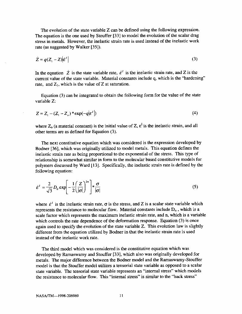
Theevolutionof thestatevariableZ canbedefinedusingthefollowing expression.Theequationis theoneusedby Stouffer[33] to modeltheevolutionof the scalardragstressin metals.However,theinelasticstrainrateis usedinsteadof the inelasticworkrate(assuggestedby Walker [35]).
= q(Z_ - Z) _t (3)
In the equation Z is the state variable rate, t_I is the inelastic strain rate, and Z is the
current value of the state variable. Material constants include q, which is the "hardening"
rate, and Z1, which is the value of Z at saturation.
Equation (3) can be integrated to obtain the following form for the value of the state
variable Z:
Z = Z 1 - (Z 1 - Zo ) * exp(-q e I ) (4)
where Zo (a material constant) is the initial value of Z, e I is the inelastic strain, and all
other terms are as defined for Equation (3).
The next constitutive equation which was considered is the expression developed by
Bodner [36], which was originally utilized to model metals. This equation defines the
inelastic strain rate as being proportional to the exponential of the stress. This type of
relationship is somewhat similar in form to the molecular based constitutive models for
polymers discussed by Ward [13]. Specifically, the inelastic strain rate is defined by the
following equation:
rr (5)d:, 2 l ( Z _Z"],__
- -f3 o°exp -Tt J ] lal
where _r is the inelastic strain rate, o is the stress, and Z is a scalar state variable which
represents the resistance to molecular flow. Material constants include Do, which is a
scale factor which represents the maximum inelastic strain rate, and n, which is a variable
which controls the rate dependence of the deformation response. Equation (3) is once
again used to specify the evolution of the state variable Z. This evolution law is slightly
different from the equation utilized by Bodner in that the inelastic strain rate is used
instead of the inelastic work rate.
The third model which was considered is the constitutive equation which was
developed by Ramaswamy and Stouffer [33], which also was originally developed for
metals. The major difference between the Bodner model and the Ramaswamy-Stouffer
model is that the Stouffer model utilizes a tensorial state variable as opposed to a scalar
state variable. The tensorial state variable represents an "internal stress" which models
the resistance to molecular flow. This "internal stress" is similar to the "back stress"
NASA/TM-- 1998-206969 11

conceptutilized in metals,asdiscussedin theprevioussection.Theinelasticstrainrateisconsideredto berelatedto thedifferencebetweentheappliedstressandtheinternalstress.Unlike thescalarstatevariableutilized in theothertwo constitutiveequations,thetensorialstatevariableis orientationdependent.Thestatevariableis assumedto beequalto zerowhenthematerialis in its virgin state,andevolvestowardsamaximumvalueatsaturation.By usingthis approach,aswill bediscussedlaterit is possibleto modeltosomeextentthenonlinearstrainrecoveryobservedduringunloadingfor manypolymers.
Theinelasticstrainrateis definedby thefollowing equation:
I1lZ0;nloO- -_ D°exp --2 ItT---_l Itr-n------_ (6)
wheret_ I is the inelastic strain rate, t_ is the stress, and f/is the state variable (called
"back stress" in metals) which represents the resistance to molecular flow. Material
constants include Do, which is a scale factor which represents the maximum inelastic
strain rate, n, which is a variable which controls the rate dependence of the deformation
response, and Zo, which represents the isotropic, initial "hardness" of the material before
any load is applied. The value of the state variable fi is assumed to be zero at the start of
loading. While not apparent from the uniaxial form of the flow equation, _ is a tensorial,
not a scalar, variable.
The evolution of the state variable f_ is described by dae following expression,
(7)
where _ is the state variable rate, t__ is the inelastic strain rate, and f_ is the current value
of the state variable. Material constants include q, which is the "hardening" rate, and
f_m, which is the maximum value of the "back stress" at saturation. This equation is
slightly different than the original equation developed by Ramaswamy and Stouffer [33],
in that the original equation includes an additional stress rate term which is not used here.
The original stress rate term was included in order to pr¢,vide for additional hardening at
low stress levels [33]. This additional hardening was folmd to not be required for the
materials analyzed in this study. For tensile loading, where the absolute value of the
inelastic strain rate equals the inelastic strain rate, Equation (7) can be integrated to obtain
the following form:
= f_,. - _,. exp(-qe I ) (8)
where exis the inelastic strain, and all other parameters are as defined for Equation (7).
Note that in this uniaxial form, Equation (8) strongly resembles Equation (4). The only
difference, the lack of a term representing the initial value of the state variable f_ in
Equation (8), is related to the fact that this initial value is always zero.
NASA/TM-- 1998-206969 12
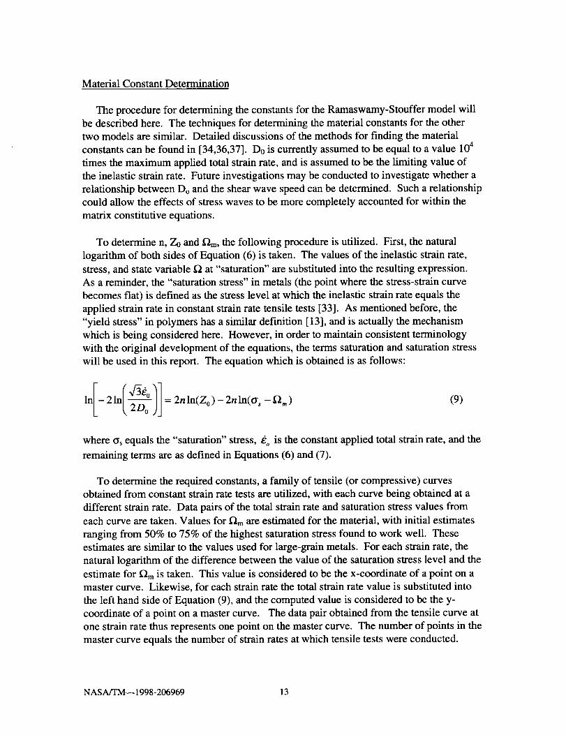
Material Constant Determination
The procedure for determining the constants for the Ramaswamy-Stouffer model will
be described here. The techniques for determining the material constants for the other
two models are similar. Detailed discussions of the methods for finding the material
constants can be found in [34,36,37]. Do is currently assumed to be equal to a value 104
times the maximum applied total strain rate, and is assumed to be the limiting value of
the inelastic strain rate. Future investigations may be conducted to investigate whether a
relationship between Do and the shear wave speed can be determined. Such a relationship
could allow the effects of stress waves to be more completely accounted for within the
matrix constitutive equations.
To determine n, Z0 and _"2m, the following procedure is utilized. First, the natural
logarithm of both sides of Equation (6) is taken. The values of the inelastic strain rate,
stress, and state variable f2 at "saturation" are substituted into the resulting expression.
As a reminder, the "saturation stress" in metals (the point where the stress-strain curve
becomes flat) is defined as the stress level at which the inelastic strain rate equals the
applied strain rate in constant strain rate tensile tests [33]. As mentioned before, the
"yield stress" in polymers has a similar definition [13], and is actually the mechanism
which is being considered here. However, in order to maintain consistent terminology
with the original development of the equations, the terms saturation and saturation stress
will be used in this report. The equation which is obtained is as follows:
I 2 ln(V/-3_° 1]In - (,-_0)j = 2nln(Zo)-2nln(tr _ -_,,,)(9)
where t_s equals the "saturation" stress, _o is the constant applied total strain rate, and the
remaining terms are as defined in Equations (6) and (7).
To determine the required constants, a family of tensile (or compressive) curves
obtained from constant strain rate tests are utilized, with each curve being obtained at a
different strain rate. Data pairs of the total strain rate and saturation stress values from
each curve are taken. Values for _"_m are estimated for the material, with initial estimates
ranging from 50% to 75% of the highest saturation stress found to work well. These
estimates are similar to the values used for large-grain metals. For each strain rate, the
natural logarithm of the difference between the value of the saturation stress level and the
estimate for _')m is taken. This value is considered to be the x-coordinate of a point on a
master curve. Likewise, for each strain rate the total strain rate value is substituted into
the left hand side of Equation (9), and the computed value is considered to be the y-
coordinate of a point on a master curve. The data pair obtained from the tensile curve at
one strain rate thus represents one point on the master curve. The number of points in the
master curve equals the number of strain rates at which tensile tests were conducted.
NASA/TM-- 1998-206969 13

A least squares regression analysis can then be performed on the master curve. As
suggested by Equation (9), the slope of the best fit line is equal to -2*n. The intercept of
the best fit line is equal to 2*n*ln(Zo). The value for tim can then be adjusted until an
optimal fit to the data is obtained.
To determine the value for m, Equation (8) is utilized At saturation, the value of the
back stress is assumed to approach the maximum value, resulting in the exponential term
approaching zero. Assuming that saturation occurs when the following condition is
satisfied:
exp(-qe_ ) = 0.01 (10)
the equation can be solved for q, where _i is the inelastic strain at saturation. The value
of the inelastic strain at saturation is estimated by determining the total strain at saturation
from a constant strain rate tensile curve, and subtracting the elastic strain from this value.
The elastic strain at saturation is computed by dividing the saturation stress by the elastic
modulus, as suggested by Equation (1). The value of the inelastic strain at saturation is
substituted into Equation (10), and solved for q. If the inelastic strain at saturation is
found to vary with strain rate, the parameter q must be computed at each strain rate and
regression techniques utilized to determine an expression for the variation of q. Note that
if compressive data is being characterized, the absolute ,0alue of the inelastic strain at
saturation is to be utilized.
An important point to note is that the meaning and ranges of the material constants
when the equations are used to model polymer deformation are not the same as when the
equations are utilized for simulating the deformation of metals. For example, when
analyzing metals using the Ramaswamy-Stouffer model, a value of n greater than or equal
to 3.0 indicates that the response is relatively rate insensitive [33]. However, in modeling
polymers, this rule of thumb most likely does not apply due to the differences in
deformation mechanisms between the two types of materials. Furthermore, the rate
dependence observed in polymers is not as dramatic as the rate dependence seen in
metals. Similarly, other rules of thumb observed in analyzing the deformation response
of metals most likely do not apply in modeling polymer deformation.
Three Dimensional Extension of Constitutive Equations
While the unidirectional representation for the Ramaswamy-Stouffer equations is
described by Equations (6) and (7), the full three dimensional formulation for the flow
equation, as described in [33], is as follows:
[ l(Zo 2 ")"] S o-niJ(11)
NASA/TM--1998-206969 14

whereSij is the deviatoricstresscomponent,_"_ij, is the component of the state variable,
t_i_ is the component of inelastic strain, n and Zo are as defined in Equation (6), and K2 is
defined as follows:
(12)
The back stress variable rate, _0 ' is defined by the following relation:
_2ij= _ qn,,e U - qni.ig:/(13)
"1where ee is the effective inelastic strain rate, defined as follows:
/-2 "1 "1
,_/ =_t_je, (14)
where repeated indices indicated summation using the standard indicial notation
definitions [33]. The remainder of the terms are as defined in Equations (6) and (7).
A key difference between the three dimensional Ramaswamy-Stouffer equations, and
other equations that use tensorial state variables, such as the Walker model [35], lies in
the definition of the tensorial state variable. In the Ramaswamy-Stouffer model, the back
stress is defined in the same manner as the stress deviator. Under uniaxial loading, the
tensorial state variable tensor has the following format:
-2
3n 0 01
0 --_f_ 01
0 0 --K]3
(15)
where D represents the uniaxial value of the state variable. In the Walker model, the state
variable tensor under uniaxial loading is defined as follows. This definition is similar to
the definition of the plastic strain tensor in standard plasticity theory [33]:
D 0 01
0 o
0 01
2
(16)
NASA/TM-- 1998-206969 15

While both tensors are deviatoric tensors, the varying definition of the state variable
results in varying definitions of the K2 term. Using the definition of f_ij specified in
Equation (16), K2 would be defined as follows:
2 3
K 2 =3(_Sq-_-'_ij)(3Su-_)q) (17)
which is what is seen in the Walker equation.
As discussed by Stouffer and Dame [33], the values of the material constants for the
full three dimensional formulation of the equations would be identical to those obtained
using the uniaxial representation of the equations. Three dimensional formulations of the
flow equation for the power law and Bodner models would be obtained in a similar
manner. Since the state variable for the power law and Bodner model is a scalar variable,
the evolution equation would not change from the uniaxial expressions except for
replacing the uniaxial inelastic strain rate with the effective inelastic strain rate.
Numerical Implementation of Ramaswamy-Stouffer Model
To implement the constitutive equations into a computer code, the following algorithm
was utilized, shown pictorially as a flow chart in Figure 1. The same basic algorithm was
utilized for all three constitutive models, and closely follows the procedure described in
[33]. For initial verification, the uniaxial representation of the models was utilized.
However, the results obtained using the uniaxial representation of the modified
Ramaswamy-Stouffer equations were compared to results obtained using the full three
dimensional formulation, and the results were identical. The computer code assumed
strain controlled loading, since when implemented into _ finite element code as a user
defined material model subroutine strains would be supplied as the input. An iterative
procedure is used, and for each time step the iteration loop is entered knowing the strain
at time t+At, and knowing the stress and the values of all of the state variables (and their
rates) at time t. The goal of the iterative procedure is to compute the stresses and the
values of the state variables (and their rates) at time t+At. An implicit trapezoidal rule
integration procedure with a constant time step was utili:_ed. Although not described
here, an explicit Runge-Kutta integration procedure was also developed and tested,
yielding results identical to the implicit integrator. For the stand alone computer codes,
implicit integration techniques are preferable to use due to their numerical stability [38].
However, when these equations are eventually implemented into transient dynamic finite
element codes, the use of explicit integration techniques for the material model might be
required due to the structure of the finite element algorithms.
The detailed procedures for implementing the Ramaswamy-Stouffer model will be
discussed in this section. Computations using the other constitutive equations would
utilize similar techniques. First, the material constants and load history are read from an
input file, and all appropriate variables are initialized. Upon entering the time step loop,
NASA/TM--1998-206969 16

thestrainrateandthevalueof anystrainratedependentmaterialpropertiesarecomputed,andthetotal strainat timet+At is determined.Thefirst timethroughtheiteration loop,anestimatefor thestressattimet+At is computedusingthefollowing forwardEulerestimate:
tr(t + At) = E[e(t + At) - e' (t) - t_' (t)At] (18)
In this equation and the following equations in this section, t represents the current time,
At represents the time increment, and all other variables are as defined in Equation (1)
and Equations (6)-(8). A forward Euler estimate for the back stress (tensorial state
variable) rate and a trapezoidal rule estimate for the back stress at time t+At are given by
the following expressions:
_(t + At) = q_,,t_' (t) - q[f_(t) + _(t)At] _' (t) (19)
At ._(t + At) = _(t) + --Z- [_(t + At) + _(t)]
Z(20)
Once the back stress is computed, the inelastic strain rate and the accumulated inelastic
strain at time t+At can be computed using the following expressions:
2 1 Z o • o'(t + At) - _(t + At)
gz'(t+At)=--_Doexp -_ Itr(t+At)_f_(t+At) ) J Itr(t+At) -_(t+At)(21)
At i61 (t + At) = e' (t) +-_-[_ (t + At) + e' (t)] (22)
After the first time through the iteration loop, the stress estimate for time t+At is
computed using the following trapezoidal rule estimate, where the inelastic strain rate
estimate for time t+At comes from the previous iteration •
tr(t + At) = E[e(t + At) - e' (t) - [_1 (t + At) + t_' (t)]-_ -_-] (23)
The back stress rate estimate is computed using the following expression, while the back
stress estimate for time t+At is computed using Equation (20):
_(t + At) = qf_,,_' (t + At) - qO(t + At)] t_I (t + At) (24)
The inelastic strain rate and inelastic strain estimate for time t+At are computed using
Equations (21) and (22).
NASA/TM--1998-206969 17
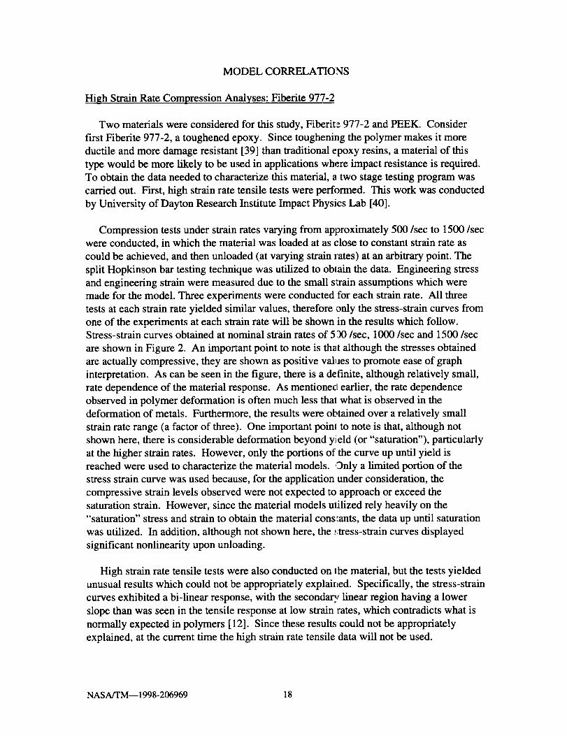
MODEL CORRELATIONS
High Strain Rate Compression Analyses: Fiberite 977-2
Two materials were considered for this study, Fiberite 977-2 and PEEK. Consider
first Fiberite 977-2, a toughened epoxy. Since toughening the polymer makes it more
ductile and more damage resistant [39] than traditional epoxy resins, a material of this
type would be more likely to be used in applications where impact resistance is required.
To obtain the data needed to characterize this material, a two stage testing program was
carried out. First, high strain rate tensile tests were performed. This work was conducted
by University of Dayton Research Institute Impact Physics Lab [40].
Compression tests under strain rates varying from approximately 500/sec to 1500/sec
were conducted, in which the material was loaded at as close to constant strain rate as
could be achieved, and then unloaded (at varying strain rates) at an arbitrary point. The
split Hopkinson bar testing technique was utilized to obtain the data. Engineering stress
and engineering strain were measured due to the small strain assumptions which were
made for the model. Three experiments were conducted for each strain rate. All three
tests at each strain rate yielded similar values, therefore only the stress-strain curves from
one of the experiments at each strain rate will be shown in the results which follow.Stress-strain curves obtained at nominal strain rates of 51)0/sec, 1000/sec and 1500/sec
are shown in Figure 2. An important point to note is that although the stresses obtained
are actually compressive, they are shown as positive val_Jes to promote ease of graph
interpretation. As can be seen in the figure, there is a definite, although relatively small,
rate dependence of the material response. As mentioned earlier, the rate dependence
observed in polymer deformation is often much less tha! what is observed in the
deformation of metals. Furthermore, the results were obtained over a relatively small
strain rate range (a factor of three). One important poinl to note is that, although not
shown here, there is considerable deformation beyond yi eld (or "saturation"), particularly
at the higher strain rates. However, only the portions of the curve up until yield is
reached were used to characterize the material models. Only a limited portion of the
stress strain curve was used because, for the application under consideration, the
compressive strain levels observed were not expected to approach or exceed the
saturation strain. However, since the material models utilized rely heavily on the
"saturation" stress and strain to obtain the material conslants, the data up until saturation
was utilized. In addition, although not shown here, the .,;tress-strain curves displayed
significant nonlinearity upon unloading.
High strain rate tensile tests were also conducted on lhe material, but the tests yielded
unusual results which could not be appropriately explained. Specifically, the stress-strain
curves exhibited a bi-linear response, with the secondary linear region having a lower
slope than was seen in the tensile response at low strain rates, which contradicts what is
normally expected in polymers [12]. Since these results could not be appropriately
explained, at the current time the high strain rate tensile data will not be used.
NASA/TM--1998-206969 18

Using the compressive curves obtained at high strain rates, the following inelastic
constants were obtained for the Fiberite 977-2 material for high strain rate compression:
Power Law: n=20, Zo=104 MPa, Z1=186 MPa, q=41
Bodner: Do=IE+07/sec., n=l.0, Zo=317 MPa, Z1=1070 MPa, q=41
Stouffer: Do=IE+07/sec., n=0.36, Zo=5560 MPa, q=41, f_m=170 MPa
A constant Poisson' s ratio of 0.40 was utilized. This value was obtained from low strain
rate tensile data, and was assumed to be valid for high strain rate compression. The high
strain rate compression modulus was found to have a slight variation with strain rate, with
average values as follows:
Strain Rate (/sec.) Modulus (GPa)
500 9.6
1000 10.8
1500 11.7
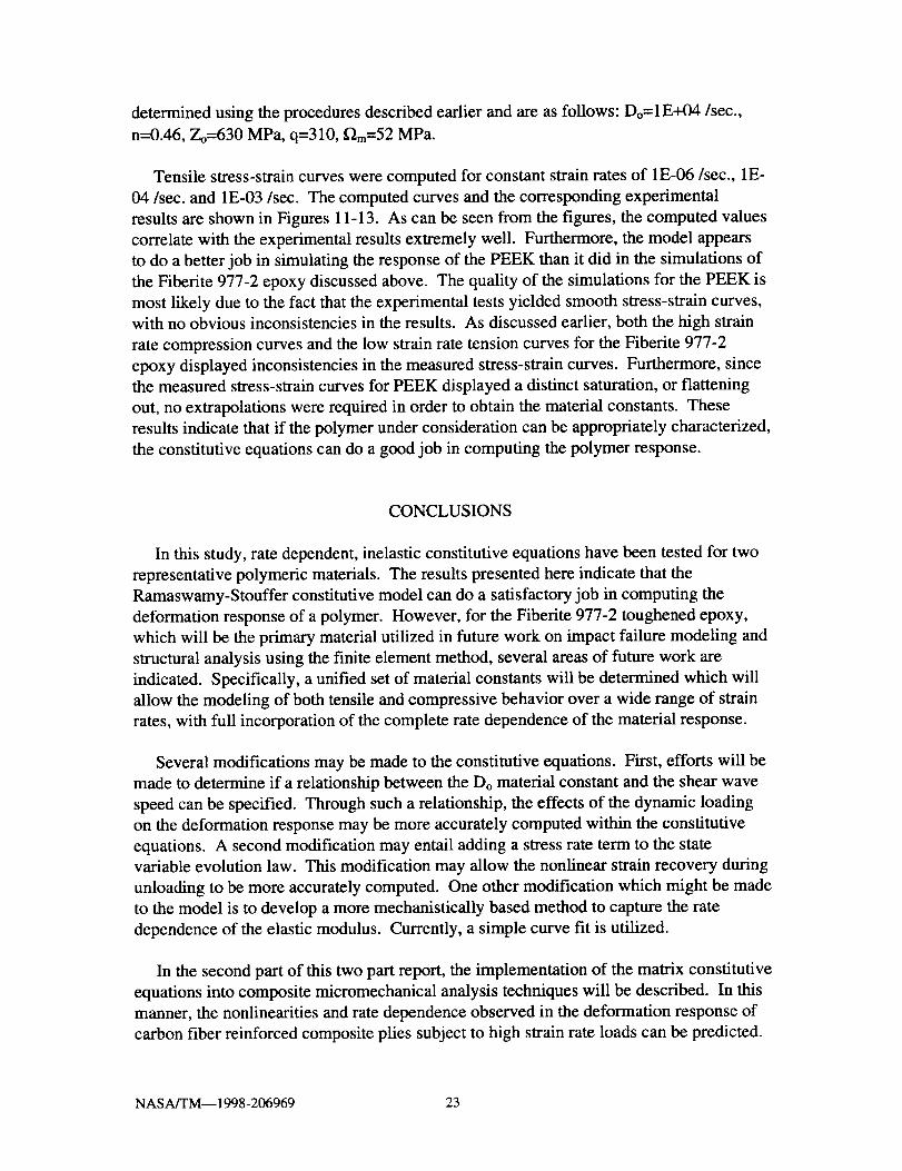
Compressive stress-strain curves computed using the power law, Bodner, and
Ramaswamy-Stouffer constitutive equations, along with experimentally obtained results,
are shown in Figures 3-5 for constant strain rates of 500/sec, 1000/sec, and 1500/sec.
As can be seen in the figures, for all three strain rates the stress levels computed by the
power law model do not correlate well with the stress levels observed in the experimental
results. However, the Bodner and Stouffer models compute nearly identical results, and
correlate much more favorably with the experimental values. Specifically, the onset of
nonlinearity, the "saturation" of the stress strain curve and the strain rate dependence are
correlated reasonably well by these two models. The fact that the Bodner and
Ramaswamy-Stouffer models yield similar results is not surprising, as the Ramaswamy-
Stouffer model is based on the Bodner equations. The discrepancies between the
experimental and computed results seen at the lower strain levels are most likely due to
the nature of the experimental tests. Specifically, in a split Hopkinson bar experiment a
certain amount of time is required for the specimen to achieve a constant strain rate.
Furthermore, at low strain levels the measured strains are often not completely accurate.
A combination of these factors most likely resulted in the shape of the experimental
curves, and the variation between the experimental and computed results.
While the Bodner and Stouffer models compute very similar results, a significant
difference between the two models can be seen in Figure 6, where a load/unload cycle
was computed using the Stouffer model for a strain rate of 500/sec. As can be seen in
the figure, there are some elements of nonlinear strain recovery in the unloading curve,
which would be expected in a polymer [10]. While the nonlinearity is most likely not as
extensive as would be present in the actual polymer, the mechanism is at least accounted
for to some extent. As mentioned earlier, incomplete modeling of the nonlinear strain
recovery during unloading is a major deficiency in utilizing viscoplastic constitutive
models developed for metals to model the nonlinear viscoelastic deformation present at
small deformation levels in polymers. This deficiency could be overcome by modifying
NASA/TM-- 1998-206969 19

the constitutive equations, or by combining viscoelastic and viscoplastic terms into one
set of constitutive equations. One possible modification which might be investigated for
the Ramaswamy-Stouffer model is to reintroduce the stress rate term into the state
variable evolution law which was included in the original equations [33]. The stress rate
term was not utilized in the equations utilized here. Thi,; term would promote a faster
decrease in the value of the state variable during unloading (due to the negative stress
rate), which might allow for more significant nonlinear strain recovery. However, any
investigation of this type is beyond the scope of the preliminary investigative study
presented here.
It is not possible to simulate nonlinear strain recovery during unloading using the
Bodner model, as the state variable monotonically approaches a saturation value and
remains constant, even during unloading. In the Ramaswamy-Stouffer model, on the
other hand, by utilizing the difference between the deviatoric stress and the "back stress"
in the inelastic strain rate equation, once the stress level decreases to a level below that of
the current back stress, the inelastic strain rate can decrease while unloading takes place.
Furthermore, as mentioned above, the structure of these equations lead themselves to
possible future modifications which might promote improved simulation of the nonlinear
strain recovery. These results indicate that the modified Ramaswamy-Stouffer is the
optimal model to use as the polymer constitutive model for this study, and the remaining
analyses will be conducted using this model.
Low Strain Rate Tension Analyses: Fiberite 977-2
To further investigate the selected material model, tensile tests at low strain rates,
ranging from 1E-04/sec. to 0.1/sec., were conducted on the Fiberite 977-2 material by
Cincinnati Testing Labs, Inc. [41]. Although the application under consideration is a high
strain rate application, these experiments were conducted in order to characterize the full
range of material behavior of the Fiberite 977-2 epoxy. By obtaining data over a wide
strain rate range, the material could be more completely characterized, and the rate
dependence of the material response could be more completely examined. In addition,
performing low strain rate tensile tests would permit the obtaining of tensile data in a
manner which would avoid the problems encountered in conducting the high strain rate
tensile tests. Axial testing was utilized to obtain the datxt. Once again, engineering stress
and engineering strain were measured due to the small strain assumptions which were
made. Stress-strain curves obtained at constant strain ra_es of 0.0001/sec., 0.01/sec. and
• 0.1/sec. are shown in Figure 7. As can be seen in the fil,ure, there is a definite rate
dependence to the tensile response. It should be noted that the unusual response seen at
low strain levels for the two higher strain rates is most likely due to difficulties which
were encountered in ramping up to the desired strain rate during the experimental tests.
A unique set of material constants was obtained from the low strain rate tensile data.It was not deemed advisable to use the material constants which were obtained from the
high strain rate compression tests to model the low strain rate tensile response. One
reason for not using the high strain rate compression constants is that in polymers there
NASA/TM--1998-206969 20

areoftendifferencesin thematerialresponsebetweentensileandcompressiveloading.First of all, theyield stressin polymershasbeenfoundto beafunction of thehydrostaticstress[13],which cancauseadifferencein thetensileandcompressiveresponse.Furthermore,in tensionpolymerscanbesubjectto theformationof crazes,whichcausesyieldingatamuchlowerstresslevelthanin situationswhereshearyielding is theprimaryyieldmechanism[42]. In compression,polymersareonly subjectto shearyielding.Crazingcanalsoleadto theformationof cracks,whichresultsin thepolymerhavingamorebrittle responsein tension,andamoreductileresponsein compression[42]. Evenif thematerialbehaviordid notchangesignificantlybetweentensionandcompressionovermajorportionsof thestress-straincurve,sincethehigh strainratecompressivematerialconstantswereobtainedoverarelativelylimited strainraterange,theconstantsobtainedmaynot bevalidover theentirerangeof strainrates.
To attemptto providefurtherinformationon the material behavior, which could then
be utilized to more completely and accurately determine a unified set of material
constants, compression tests at low strain rates are currently being conducted at the
NASA Lewis Research Center. From this data, a more complete set of compressive
material constants will be obtained. In addition, by comparing the low strain rate
compression response to the low strain rate tensile response, attempts will be made to
obtain a unified set of material constants covering both tensile and compressive behavior
over the full range of strain rates. A unified set of material constants will be critical in
actual applications, such as utilizing the constitutive model in a transient dynamic finite
element analysis to model impact problems. Furthermore, the rate dependence of the
material response can be more completely determined by obtaining a unified set of
material constants. If the low strain rate compression data cannot be obtained, the high
strain rate compression data and the low strain rate tensile data might be combined using
a suitable set of approximations to obtain a unified set of material constants.
To obtain the low strain rate tensile material constants, the stress-strain curves had to
be extrapolated since the tensile specimens failed before "saturation" occurred. To obtain
an estimate of the saturation stress and strain, the curves for the strain rates of 0.0001/sec
and 0.1/sec were extrapolated using a quadratic curve fit. Since the specimens failed in
tension before the saturation level was reached, it was assumed that matching the actual
saturation stress would not be critical. Once low strain rate compression data is obtained,
this data will be used to refine the material constants. By extrapolating, the following
estimates for saturation stress and saturation strain for the low strain rate tensile data were
obtained:
Strain Rate (/sec.) Saturation Stress (MPa)
1E-04 97 0.055
0.1 110 0.053
Saturation Strain
NASA/TM--1998-206969 21

Thelow strainratetensilematerialconstantsfor the l_:amaswamy-Stouffermodel,which weredeterminedusingtheprocedurediscussedpreviously,areasfollows:Do=IE+04/sec.,n--0.50,Zo=1030MPa,q=160,tim=69MPa. Thelow strainratetensileelasticmoduluswasfoundto beratedependentasfollows:
Strain Rate (/sec.) Modulus (GPa)
1E-04 3.65
0.01 4.13
0.1 4.82
It should be noted that the low strain rate tensile modulus values are somewhat less than
the high strain rate compressive modulus values. Assuming that the tensile and
compressive moduli follow similar trends with strain rate, this modulus variation withstrain rate is consistent with what has been observed in literature, as described in the
background section of this report. A constant Poisson's ratio of 0.40 was once again
utilized.
Tensile stress-strain curves were computed for constant strain rates of 0.0001/sec,
0.01/sec, and 0.1/sec using the Ramaswamy-Stouffer constitutive equations and the low
strain rate tensile material constants presented above, and the results are shown in Figures
8-10. As can be seen in the figures, the computed results correlate with the experimental
values reasonably well overall. In particular, the nonlinearity of the stress-strain curves is
correlated reasonably well for all three strain rates. Any discrepancies between the
experimental and computed results is most likely due to the approximations which were
made in estimating the saturation stress and strain. Since the constants used in the
constitutive equations are strongly dependent on these wdues, any inaccuracies in these
values could signifcanfly affect the computed results. Furthermore, for the experiments
conducted at strain rates of 0.01/sec and 0.1/sec, as mentioned earlier difficulties were
encountered during the tests in ramping up to the desired strain rate, which could have
affected the experimental results.
Low Strain Rate Tension Analyses: PEEK
To determine if the selected constitutive model can accurately compute the stress-
strain behavior of a variety of materials, plus to verify the low strain rate tensile
capabilities of the constitutive equations for a material which has a distinct "saturation" in
the stress-strain tensile response, a PEEK (polyetheretherketone) thermoplastic was also
characterized and modeled. Tensile stress strain curves over strain rates ranging from 1E-
06/sec. to 1E-03/sec. were obtained by Bordonaro and Krempl [43]. As mentioned
previously, the tensile curves for this material exhibit a distinct saturation, or flattening
out, unlike the tensile curves for the Fiberite 977-2 epoxy. This result is to be expected
since a thermoplastic like PEEK is expected to be more cluctile than the toughened epoxy
Fiberite 977-2. A constant elastic modulus of 4000 MPa and a constant Poisson' s ratio of
0.40 were utilized. The inelastic constants for the Ramaswamy-Stouffer model were
NASA/TM-- 1998-206969 22
determinedusingtheproceduresdescribedearlierandareasfollows: Do=IE+04/sec.,n-0.46,Zo=630MPa,q-310, f_m=52MPa.
Tensilestress-straincurveswerecomputedfor constantstrainratesof 1E-06/sec.,1E-04/sec.and 1E-03/sec.Thecomputedcurvesandthecorrespondingexperimentalresultsareshownin Figures11-13.As canbeseenfrom thefigures,thecomputedvaluescorrelatewith theexperimentalresultsextremelywell. Furthermore,themodelappearsto doabetterjob in simulatingtheresponseof thePEEK thanit did in thesimulationsoftheFiberite977-2epoxydiscussedabove.Thequalityof thesimulationsfor thePEEKismostlikely dueto thefact thattheexperimentaltestsyieldedsmoothstress-straincurves,with noobviousinconsistenciesin theresults.As discussedearlier,both thehigh strainratecompressioncurvesandthelow strainratetensioncurvesfor theFiberite977-2epoxydisplayedinconsistenciesin themeasuredstress-straincurves.Furthermore,sincethemeasuredstress-straincurvesfor PEEKdisplayedadistinct saturation,or flatteningout, noextrapolationswererequiredin orderto obtainthematerialconstants.Theseresultsindicatethatif thepolymerunderconsiderationcanbeappropriatelycharacterized,theconstitutiveequationscandoagoodjob in computingthepolymerresponse.
CONCLUSIONS
In this study,ratedependent,inelasticconstitutiveequationshavebeentestedfor tworepresentativepolymericmaterials.TheresultspresentedhereindicatethattheRamaswamy-Stoufferconstitutivemodelcandoa satisfactoryjob in computingthedeformationresponseof apolymer. However,for theFiberite977-2toughenedepoxy,whichwill betheprimarymaterialutilized in futureworkon impactfailuremodelingandstructuralanalysisusingthefinite elementmethod,severalareasof futurework areindicated.Specifically,aunifiedsetof materialconstantswill bedeterminedwhich willallow themodelingof bothtensileandcompressivebehaviorovera widerangeof strainrates,with full incorporationof thecompleteratedependenceof thematerialresponse.
Severalmodificationsmaybemadeto theconstitutiveequations.First,effortswill bemadeto determineif arelationshipbetweentheDomaterialconstantandtheshearwavespeedcanbespecified.Throughsucharelationship,theeffectsof thedynamicloadingon thedeformationresponsemaybemoreaccuratelycomputedwithin theconstitutiveequations.A secondmodificationmayentailaddinga stressratetermto thestatevariableevolutionlaw. Thismodificationmayallow thenonlinearstrainrecoveryduringunloadingto bemoreaccuratelycomputed.Oneothermodificationwhichmight bemadeto themodel is to developamoremechanisticallybasedmethodto capturetheratedependenceof theelasticmodulus.Currently,asimplecurvefit is utilized.
In thesecondpartof this two part report,the implementationof thematrix constitutiveequationsinto compositemicromechanicalanalysistechniqueswill bedescribed.In thismanner,thenonlinearitiesandratedependenceobservedin thedeformationresponseofcarbonfiber reinforcedcompositepliessubjectto high strainrate loadscanbepredicted.
NASA/TM--1998-206969 23

Furthermore, the nonlinearities observed in the composite response can be predicted
based on the nonlinear response of the matrix constituenr:, which is the actual mechanism
taking place.
Once the deformation model is completed, an impact failure model will be developed
based on local failure mechanisms, and the combined deformation and failure model will
be implemented into a transient dynamic finite element code. Full deformation and
failure analyses will then be conducted on structures subject to impact loading conditions.
°
,
.
,
,
,
.
+
REFERENCES
Harding, J.; and Welsh, L.M.: A Tensile Testing Technique for Fiber Reinforced
Composites at Impact Rates of Strain. J. Mat. Sci., Vol. 18, pp. 1810-1826, 1983.
Staab, G.H.; and Gilat, A.: High Strain Rate Response of Angle-Ply Glass/Epoxy
Laminates. J. Comp. Mat., Vol. 29, pp. 1308-1320, 1995.
Choe, G.H.; Finch, W.W. Jr.; and Vinson, J.R.: Compression Testing of Composite
Materials at High Strain Rates. Proceedings of the Fourth Japan-U.S. Conference on
Composite Materials, Technomic Publishing Co., Lancaster, PA., pp. 82-91, 1988.
Nicholas, T.: Material Behavior at High Strain Rates. Impact Dynamics, J. Zukas; T.
Nicholas; H. Swift; L. Greszczuk; and D. Curran, eds., Krieger Publishing Co.,
Malabar, FL., pp. 277-332, 1992.
Harding, J.: The High Speed Punching Behavior of =Woven-Roving Glass-Reinforced
Composites. Proceedings of the Conference on Mechanical Properties at High Rates
of Strain, Inst. Phys. Conf. Ser. No. 47, Institute of Physics, Bristol, England, pp.
318-330, 1979.
Daniel, I.M.; Hsiao, H.M.; and Cordes, R.D.: Dynarrfic Response of Carbon/Epoxy
Composites. High Strain Rate Effects on Polymer, Metal and Ceramic Matrix
Composites and Other Advanced Materials, AD-Vol. 48, Y.D.S. Rajapakse and J.R.
Vinson, eds., ASME, pp. 167-177, 1995.
Daniel, I.M.; Hamilton, W.G.; and LaBedz, R.H.: Suain Rate Characterization of
Unidirectional Graphite/Epoxy Composite. Composite Materials: Testing and
Design (Sixth Conference), ASTM STP 787, I.M. Daniel, ed., American Society of
Testing and Materials, pp. 393-413, 1982.
AI-Salehi, F.A.R.; AI-Hassani, S.T.S.; and Hinton, M.J.: An Experimental
Investigation into the Strength of Angle Ply GRP Tubes under High Rates of Loading.
J. Comp. Mat., Vol. 23, pp. 288-305, 1989.
NASA/TM-- 1998-206969 24

. Groves, S.E.; Sanchez, R.J.; Lyon, R.E.; and Brown, A.E.: High Strain Rate Effects
for Composite Materials. Composite Materials: Testing and Design (Eleventh
Volume), ASTM STP 1206, E.T. Camponeschi, Jr., ed., American Society of Testing
and Materials, pp. 162-176, 1993.
10. Rosen, S.L.: Fundamental Principals of Polymer Materials. John Wiley and Sons,
New York, 1982.
11. Cessna, L.C. Jr.; and Sternstein, S.S.: Viscoelasticity and Plasticity Considerations in
the Fracture of Glasslike High Polymers. Fundamental Phenomena in the Material
Sciences, 4, Fracture of Metals, Polymers and Glasses, L.J. Broutman, J.J. Duga, and
J.J. Gilman, eds., Plenum Press, New York, pp. 45, 1967.
12. Miller, E.: Introduction to Plastics and Composites. Marcel Dekker, Inc., New York,
1996.
13. Ward, I.M.: Mechanical Properties of Solid Polymers. John Wiley and Sons, New
York, 1983.
14. Amoedo, J.: Rate-Dependent Constitutive Equations and Process Modeling of
Polymer Materials. PhD Dissertation, Rensselaer Polytechnic Institute, Troy, New
York, 1990.
15. Boyce, M.C.; Parks, D.M.; and Argon, A.S.: Large Inelastic Deformation of Glassy
Polymers. Part I: Rate Dependent Constitutive Model. Mechanics of Materials. Vol.
7, pp. 15-33, 1988.
16. Hasan, O.A.; and Boyce, M.C.: A Constitutive Model for the Nonlinear Viscoelastic
Viscoplastic Behavior of Glassy Polymers. Poly. Eng. & Sci., Vol. 35, pp. 331-344,1995.
17. Qian, Z. and Liu, S.: Unified Constitutive Modeling from Viscoelasticity and
Viscoplasticity of Polymer Matrix Composites. Proceedings of the American Society
of Composites Twelfth Technical Conference, R.F. Gibson and G.M. Newaz, eds.,
Technomic Publishing Co., Lancaster, PA, pp. 165-174, 1997.
18. Bordonaro, C.M.: Rate Dependent Mechanical Behavior of High Strength Plastics:
Experiment and Modeling. PhD Dissertation, Rensselaer Polytechnic Institute, Troy,
New York, 1995.
19. Krempl, E.; McMahon, J.J.; and Yao, D.: Viscoplasticity Based on Overstress with a
Differential Growth Law for the Equilibrium Stress. Mech. Mat., Vol. 5, pp. 35,
1986.
NASA/TM--1998-206969 25

20. Valisetty, R.R.; and Teply, J.L.: Overall Instantaneous Viscoplastic Properties of
Composites. J. Comp. Mat., Vol. 26, pp. 1708-1724, 1992.
21. Zhang, C.; and Moore, I.D.: Nonlinear Mechanical Response of High Density
Polyethylene. Part II: Uniaxial Constitutive Model. Poly. Eng. & Sci., Vol. 37, pp.
414-420, 1997.
22. Weeks, C.A.; and Sun, C.T.: Nonlinear Rate Dependence of Thick-Section
Composite Laminates. High Strain Rate Effects on Polymer, Metal and Ceramic
Matrix Composites and Other Advanced Materials, AD-Vol. 48, Y.D.S. Rajapakse
and J.R. Vinson, eds., ASME, pp. 81-95, 1995.
23. Yoon, K.J.; and Sun, C.T.: Characterization of Elastic-Viscoplastic Properties of an
AS4/PEEK Thermoplastic Composite. J. Comp. Mat., Vol. 25, pp. 1277-1296, 1991.
24. Gates, T.S.; and Sun, C.T.: Elastic/Viscoplastic Constitutive Model for Fiber
Reinforced Thermoplastic Composites. AIAA Journal, Vol. 29, pp. 457-463, 1991.
25. Thiruppukuzhi, S.V.; and Sun, C.T.: A Viscoplasticity Model for High Strain Rate
Characterization of Polymeric Composites. Proceedings of the American Society of
Composites Twelfth Technical Conference, R.F. Gibson and G.M. Newaz, eds.,
Technomic Publishing Co., Lancaster, PA, pp. 450-z59, 1997.
26. Espinosa, H.D.; Lu, H.C.; Dwivedi, S.K.; and Zavatlieri, P.D.: A Finite Deformation
Anisotropic Plasticity Model for Fiber Reinforced Composites. Proceedings of the
American Society of Composites Twelfth Technical Conference, R.F. Gibson and
G.M. Newaz, eds., Technomic Publishing Co., Lancaster, PA, pp. 429-441, 1997.
27. O'Donoghue, P.E.; Anderson, C.E. Jr.; Friesenhahn, G.J.; and Parr, C.H.: A
Constitutive Formulation for Anisotropic Materials Suitable for Wave Propagation
Computer Programs. J. Comp. Mat., Vol. 26, pp. 1860-1884, 1992.
28. Tay, T.E.; Ang, H.G.; and Shim, V.P.W.: An Empirical Strain Rate-Dependent
Constitutive Relationship for Glass-Fibre Reinforced Epoxy and Pure Epoxy.
Composite Structures, Vol. 33, pp. 201-210, 1995.
29. Espinosa, H.D.; Emore, G.; and Xu, Y.: High Strait_ Rate Behavior of Composites
with Continuous Fibers. High Strain Rate Effects on Polymer, Metal and Ceramic
Matrix Composites and Other Advanced Materials, _d)-Vol. 48, Y.D.S. Rajapakse
and J.R. Vinson, eds., ASME, pp. 7-18 1995.
30. Clements, B.E.; Johnson, J.N.; and Hixson, R.S.: Stress Waves in Composite
Materials. Physical Review E, Vol. 54, pp. 6876-68_8, 1996.
31. Aboudi, J.: Mechanics of Composite Materials: A Unified Micromechanical
Approach. Elsevier, New York, 1991.
NASA/TM-- 1998-206969 26

32. Aidun, J.R.; and Addessio, F.L.: An Enhanced Cell Model with Nonlinear Elasticity.
J. Comp. Mat, Vol. 30, pp. 248-280, 1996.
33. Stouffer, D.C.; and Dame, L.T.: Inelastic Deformation of Metals. Models,
Mechanical Properties and Metallurgy. John Wiley and Sons, New York, 1996.
34. Saleeb, A.F.; and Arnold, S.M.: A General Reversible Hereditary Constitutive
Model: Part 1-Theoretical Developments. NASA TM-107493, National Aeronautics
and Space Administration, 1997.
35. Walker, K.P.: Research and Development Program for Nonlinear Structural
Modeling with Advanced Time-Temperature Dependent Constitutive Relationships.
NASA CR-165533, National Aeronautics and Space Administration, 1981.
36. Bodner, S.R.: Review of a Unified Elastic-Viscoplastic Theory. Unified Constitutive
Equations for Creep and Plasticity, A.K. Miller, ed., Elsevier, Barking, Essex,
England, 1987.
37. Stouffer, D.C.; and Bodner, S.R.: A Relationship Between Theory and Experiment
for a State Variable Constitutive Equation. Mechanical Testing for Deformation
Model Development, ASTM STP 765, R.W. Rohde and J.C. Swearengen, eds.,
American Society of Testing and Materials, pp. 239-250, 1982.
38. Kreyszig, E.: Advanced Engineering Mathematics, 7th Edition. John Wiley and Sons,
New York, 1992.
39. Almen, G.R.; Byrens, R.M.; MacKenzie, P.D.; Maskell, R.K; McGrail, P.T.; and
Sefton, M.S.: 977 - A Family of New Toughened Epoxy Resins. 34 th International
SAMPE Symposium, pp. 259-270, 1989.
40. Sawas, O.: Compression and Tension Characterization of Neat Resin and Composite
Systems at High Strain Rate. UDR-TR-97-157, University of Dayton Research
Institute, Experimental and Applied Mechanics Group, 1997.
41. Gieseke, B.: Private Communication, Cincinnati Testing Laboratories, Inc., 1997.
42. Kinloch, A.J.; and Young, R.J.: Fracture Behavior of Polymers. Elsevier, Barking,
Essex, England, 1983.
43. Bordonaro, C.M.; and Krempl, E.: The Rate-Dependent Mechanical Behavior of
Plastics: A Comparison Between 6/6 Nylon, Polyetherimide and
Polyetheretherketone. Use of Plastics and Plastic Composites: Materials and
Mechanics Issues, MD-Vol. 46, V.K. Stokes, ed., ASME, pp. 43-56, 1993.
NASA/TM--1998-206969 27

IncrementTimeStep
Yes
f_
Start )
IRead in Load Historyand Material Constants
Compute Strain Rateand Total Strain
[Compute Stress ]
Compute Back Stress,Back Stress Rate,Inelastic Strain
Inelastic Strain Rate
I t+
New Load stop?IlEnd I
No
Figure 1: Flow Diagram for Matrix Constitutive Equation Algorithm
3O0
250
2O0
150
High Rate Compression: 977-2 Resin
100
5o
o
.o..OO.
O.O0E+O0 2.O0E-02 4.00E-02 6.O0E-02 8.O0E-02 1.00E-01 1.20E-01 1.40E.01 1.60E-01 1.80E-01
Sir=an
Figure 2: High Strain Rate Compression Cu]wes for 977-2 Resin
_Stnlin Rate--5OO/sec. ]
i_ _ $Vain Rate=1000/sec._" " - Strain Rate=1500/sec.
NASA/TM--1998-206969 28

360
250
260
150
100
High Rate Compression: 977-2 Resin, Strain Rate=500/sec.
5o
" " Power Law
Bodner Model
" Stouffer Model
0
0.60E+00 2.00E-02 4.60E-02 6.00E-02 8.00E*02 1.60E-01 1.20E-01 1.40E-01 1.60E-01 1.80E-01
Strain
Figure 3: Model Correlations for 977-2 Resin at Compressive Strain Rate of 500/sec.
300
250
200
_ 150
IO0
50
High Rate Compression: 977-2 Resin, Strain Rate=1000 Isec.
0
O.OOE+O0 2.00E*02 4.00E-02 6.00E-02 8.00E-02 1,00E-01 1.20E-01 1.40E-01 1.60E-01
Strain
1.80E-01
Experimental
- - - Power Law
_ Bodner Model
" Stouffer Mode
Figure 4: Model Correlations for 977-2 Resin at Compressive Strain Rate of 1000/sec.
NASA/TM--1998-206969 29
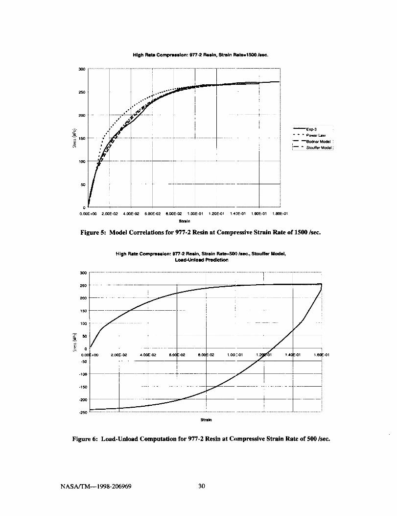
3ool..............l
250
2O0
_150
100
High Rate Compression: 977-2 Resin, Stmln Rate=IS00 lsec.
5o
0
O.O0E+O0 2.O0E-02 1.O0E-01 1.80E-01
I

8O
7O
6O
5O
40
30
2O
tO
Low Rate Tension: 977-2 Resin
I
0 0.005 0.01 0.015 0.02
Strain
0.025 0.03
Strain Rate=O.O001 Isec._Strain Rate=O.01 Isec.
[" 7 " Strain Rate=O.1/sec_ J
Figure 7: Low Strain Rate Tensile Curves for 977-2 Resin
80
7O
6O
5O
40
3O
20
10
0
0
Low Rate Tension: 977-2 Resin, Strain Rate=0.0001 Isec.
0.005 0.01 0.015 0.02 0.025 0.03
Strain
0.035
Figure 8: Model Correlations for 977-2 Resin at Tensile Strain Rate of 0.0001/sec.
NASA/TM-- 1998-206969 31

6O
50
4O
30
2O
10
Low Rate Tenlion: 977-2 Resin, Strain Rab_---0.01/sac.
r
O,(X)2 0.004 0.006 0,008 0.01 0.0t2 0.014 0.016
Strain
Figure 9: Model Correlations for 977-2 Resin at Tensile Strain Rate of 0.01/sec.
_ Experimental
m BSIouffer Model
8O
7O
6O
5O
"_"40
10
Low Rate Tension: 977-2 Resin, Strain Rare--0.1 INC.
'
0.002 0.004 0.006 0.008 0.01 0.012 0.014 0.016 0.018 0.02
Strain
Figure 10: Model Correlations for 977-2 Resin at Tensile Strain Rate of 0.1/sec.
NASA/TM-- 1998-206969 32
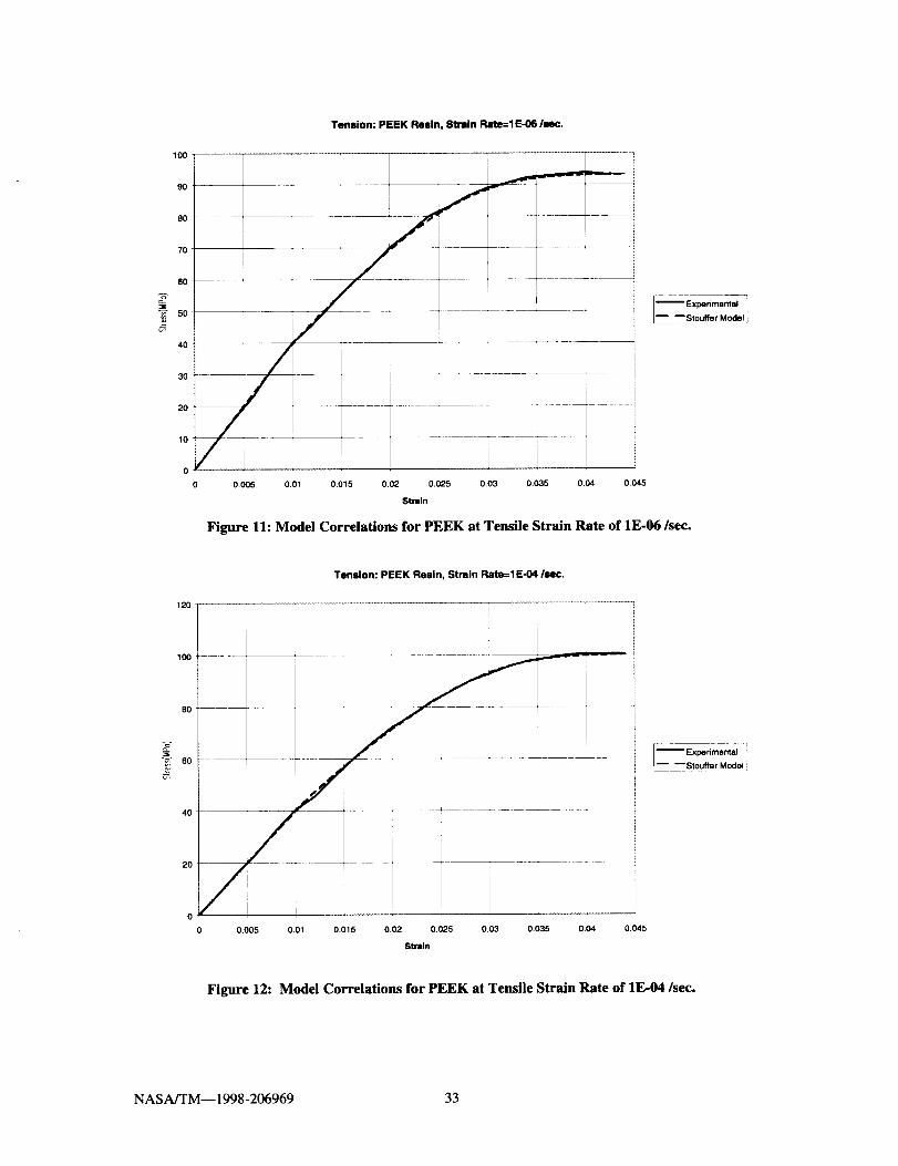
100
90
8O
7O
4O
30
20
10
0
0
Tension: PEEK Resin, Strain Rate=lE-06 INC.
Experimental
L_ mStouffer Model
I i0.005 0,01 0.015 0.02 0.025 0.03 0.035 0.04 0.045
Strain
Figure 11: Model Correlations for PEEK at Tensile Strain Rate of 1E-06/sec.
120
100
8O
"_ 60
Tension: PEEK Resin, Strain Rate=lE-04 Isec.
--Exp.nme.tal-"r Stouffer Model
40
2O
0 0.005 0.01 0.015 0.02 0.025 0,03 0.035 0.04 0,045
Strain
Figure 12: Model Correlations for PEEK at Tensile Strain Rate of 1E-04/sec.
NASA/TM--1998-206969 33

120
100
8O
4O
2O
Tension: PEEK Resin, Strain Rate=l E-03 Isec.
0.005 0.01 0.015 0.02 0.025 0.03 [J.035 0.04 0.045
8trllln
Figure 13: Model Correlations for PEEK at Tensile Strain Rate of 1E-03/sec.
I_ Experimental
_ Stouffer Model
NASA/TM-- 1998-206969 34
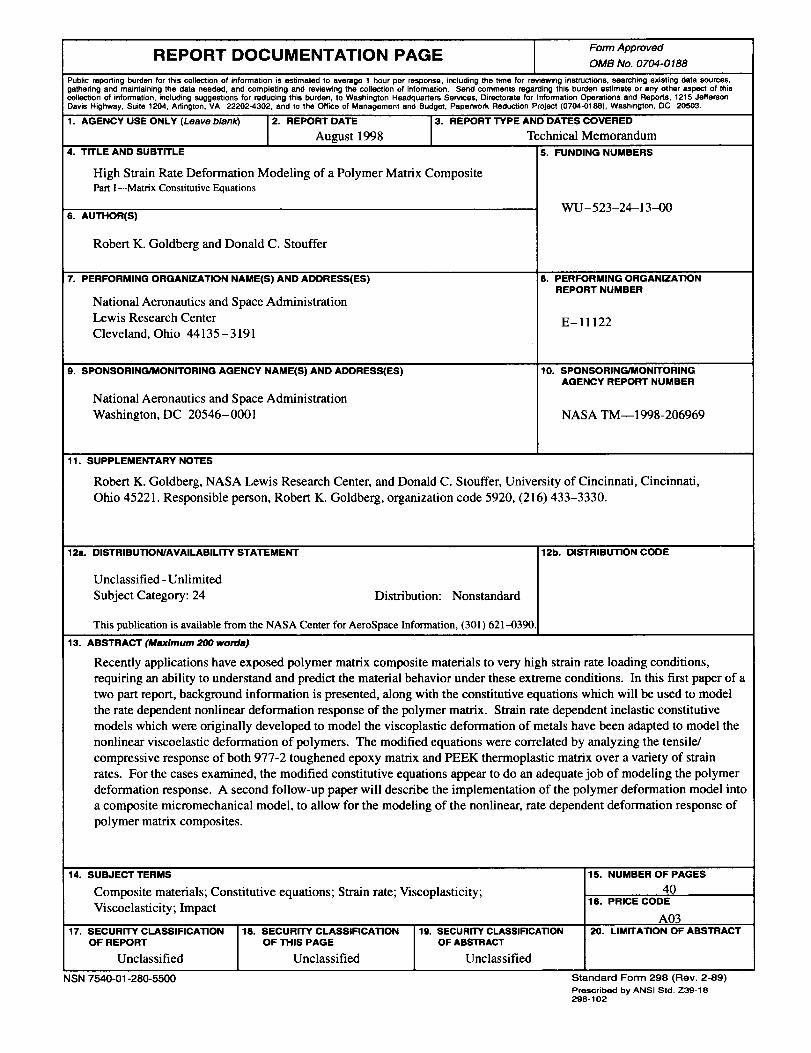
REPORT DOCUMENTATION PAGE Form ApprovedOMB No. 0704-0188
Public reporting burden for this collection of information is estimated to average 1 hour per response, including the time for rmnewtng instructions, searching existing data sources,gathering and maintaining the data needed, and completing and reviewing the collection of information. Send comments regarding this burden estimate or any other aspect of thiscollection of information, including suggestions for reducing this burden, to Washington Headquarters Services, Directorate for Information Operations and Reports, 1215 JeffersonDavis Highway, Suite 1204, Adington, VA 22202-4302, and to the Office of Management and Budget, Paperwork Reduction Project (0704-0188), Washington, DC 20503.
1. AGENCY USE ONLY (Leave blank) 2. REPORT DATE 3. REPORT TYPE AND DATES COVERED
August 1998 Technical Memorandum
4. TITLE AND SUBTITLE 5. FUNDING NUMBERS
High Strain Rate Deformation Modeling of a Polymer Matrix Composite
Part 1--Matrix Constitutive Equations
6. AUTHOR(S)
Robert K. Goldberg and Donald C. Stouffer
7. PERFORMING ORGANIZATION NAME(S) AND ADDRESS(ES)
National Aeronautics and Space Administration
Lewis Research Center
Cleveland, Ohio 44135-3191
9. SPONSORING/MONITORING AGENCY NAME(S) AND ADDRESS(ES)
National Aeronautics and Space Administration
Washington, DC 20546- 0001
WU-523-24-13-00
8. PERFORMING ORGANIZATION
REPORT NUMBER
E-11122
10. SPONSORING/MONITORING
AGENCY REPORT NUMBER
NASA TM--1998-206969
11. SUPPLEMENTARY NOTES
Robert K. Goldberg, NASA Lewis Research Center, and Donald C. Stouffer, University of Cincinnati, Cincinnati,
Ohio 45221. Responsible person, Robert K. Goldberg, organization code 5920, (216) 433-3330.
12a. DISTRIBUTION/AVAILABILITY STATEMENT 12b. DISTRIBUTION CODE
Unclassified - Unlimited
Subject Category: 24 Distribution: Nonstandard
This publication is available from the NASA Center for AeroSpace Information, (301) 621-0390.
13. ABSTRACT (Maximum 200 words)
Recently applications have exposed polymer matrix composite materials to very high strain rate loading conditions,
requiring an ability to understand and predict the material behavior under these extreme conditions. In this first paper of a
two part report, background information is presented, along with the constitutive equations which will be used to model
the rate dependent nonlinear deformation response of the polymer matrix. Strain rate dependent inelastic constitutive
models which were originally developed to model the viscoplastic deformation of metals have been adapted to model the
nonlinear viscoelastic deformation of polymers. The modified equations were correlated by analyzing the tensile/
compressive response of both 977-2 toughened epoxy matrix and PEEK thermoplastic matrix over a variety of strain
rates. For the cases examined, the modified constitutive equations appear to do an adequate job of modeling the polymer
deformation response. A second follow-up paper will describe the implementation of the polymer deformation model into
a composite micromechanical model, to allow for the modeling of the nonlinear, rate dependent deformation response of
polymer matrix composites.
14. SUBJECT TERMS
Composite materials; Constitutive equations; Strain rate; Viscoplasticity;
Viscoelasticity; Impact
17. SECURITY CLASSIFICATION
OF REPORT
Unclassified
NSN 7540-01-280-5500
15. NUMBER OF PAGES
4016. PRICE CODE
A0318. SECURITY CLASSIFICATION 19. SECURITY CLASSIFICATION 20. LIMITATION OF ABSTRACT
OF THIS PAGE OF ABSTRACT
Unclassified Unclassified
Standard Form 298 (Rev. 2-89)
Prescribed by ANSI Std. Z39-18298-102