High-speed linear array cameras · The magnitude or phase is calculated from the data defined by...
52
1 Glaz LineScan-I Overview Glaz LineScan-I is a low-noise camera with 16-bit resolution. Extremely low noise-levels can be obtained by a selection of hardware and/or software averaging modes. Combined with powerful PC-based data processing software, a multi-camera measuring system can be configured quickly and effortlessly. Glaz LineScan-I cameras are available with two different firmware flavours: PulseSync and TimeFill. PulseSync is recommended for synchronised single- and multi-camera systems. TimeFill is recommended for applications requiring large temporal fill factors. Glaz UI (a stand-alone application) or LabView can be used to configure and communicate with the cameras. Measurements with single- or multi-camera configurations can be configured, using XML-based script files. This provides a flexible way to define calculations, that need to be performed on the measured data. All data processing is performed in optimised, multi-threaded libraries, thereby providing the best possible performance. Glaz UI Standalone user interface Optimised PC data processing LabView integration Glaz LineScan-I Low-noise, high-speed cameras Glaz-PD Photo-diode digitizer - Low-noise - 16-bit resolution - High-speed USB interface - USB-powered - LabView integration - Flexible XML-based configurations - Application-specific firmware flavours LineScan-I High-speed linear array cameras Glaz
Transcript of High-speed linear array cameras · The magnitude or phase is calculated from the data defined by...
1 Glaz LineScan-I
Overview
Glaz LineScan-I is a low-noise camera with 16-bit resolution. Extremely low noise-levels can be obtained by a selection of hardware and/or software averaging modes. Combined with powerful PC-based data processing software, a multi-camera measuring system can be configured quickly and effortlessly.
Glaz LineScan-I cameras are available with two different firmware flavours: PulseSync and TimeFill. PulseSync is recommended for synchronised single- and multi-camera systems. TimeFill is recommended for applications requiring large temporal fill factors.
Glaz UI (a stand-alone application) or LabView can be used to configure and communicate with the cameras. Measurements with single- or multi-camera configurations can be configured, using XML-based script files. This provides a flexible way to define calculations, that need to be performed on the measured data. All data processing is performed in optimised, multi-threaded libraries, thereby providing the best possible performance.
Glaz UIStandalone user interface
Optimised PC dataprocessing
LabViewintegration
Glaz LineScan-ILow-noise, high-speed camerasGlaz-PDPhoto-diode digitizer
- Low-noise
- 16-bit resolution
- High-speed USB interface
- USB-powered
- LabView integration
- Flexible XML-based configurations
- Application-specific firmware flavours
LineScan-I High-speed linear array cameras
Gla
z

2 Glaz LineScan-I
Specifications
Characteristic Value Unit
PC Interface
PC interface USB 2.0 (high-speed)
Data transfer rate1 >20 MB/s
Maximum USB cable length 3 m
Linear sensor Sensor type CMOS
Supported sensors Hamamatsu S12198-1024Q Hamamatsu S10453-1024Q Hamamatsu S11639 Hamamatsu S11639-01
Optical integration time PulseSync: 2 – 5,000 TimeFill: 2 – 400,000
s
Hamamatsu S12198-1024Q/S10453-1024Q Pixel count 1024
Scan rate (half-speed clock) 3,500 lines/s
Scan rate (full-speed clock) 7,000 lines/s
Spectral response range 200 – 1000 nm
Noise level (single scan) <520 μOD 2
Noise level (512 averaged scans) <25 μOD
Dynamic range3 (single scan) >1,900
Dynamic range (512 averaged scans) >40,000
Hamamatsu S11639/S11639-01 Pixel count 2048
Scan rate (half-speed clock) 1,700 lines /s
Scan rate (full-speed clock) 3,500 lines /s
Spectral response range 200 – 1000 nm
Noise level (single scan) <530 μOD
Noise level (512 averaged scans) <30 μOD
Dynamic range (single scan) >1,800
Dynamic range (512 averaged scans) >33,000
Digitizer Resolution 16 bit
Full-scale reading 65535
ENOB (effective number of bits) 13.5 bit
Drift 100 ppm/OC
Total analogue front-end noise level <1 mVRMS
External trigger
Signal type 5V-TTL
Trigger edge rising
Positive-going threshold voltage 2.8 V
Negative-going threshold voltage 2.0 V
Minimum trigger pulse width 1 s
Programmable trigger delay 0 - 200 ms
Programmable trigger delay resolution 0.1 s
Table 1 Specifications for LineScan-I.
1 Using dedicated USB 2.0 port. 2 OD is the relative amplitude with respect to full-scale value. 3 Dynamic range is defined as the ratio of the full-scale value and the RMS noise value.
3 Glaz LineScan-I
Hardware description
Dimensions
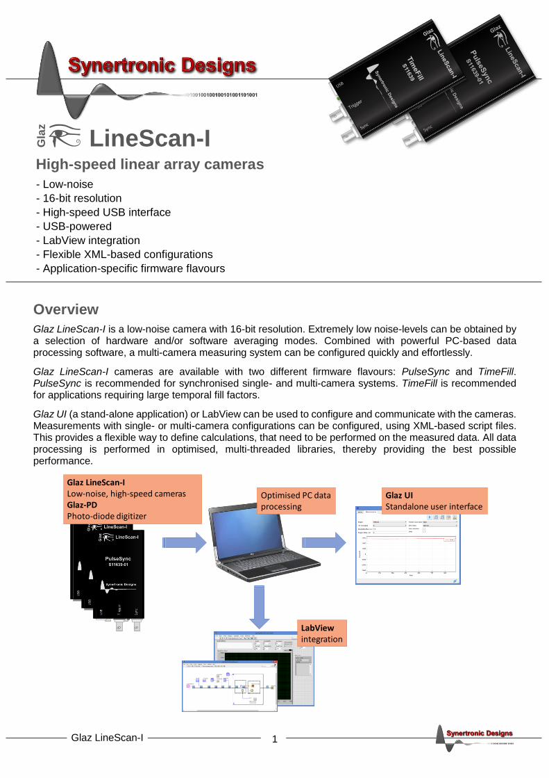
Figure 1 Mechanical dimensions and legend.
Ports
Port Type Function
USB USB-B Data connection to a PC. Also provides the camera with power.
Trigger BNC External trigger input.
Sync BNC Synchronisation signal for multi-camera operation.
Table 2 Connectors.
LEDs
LED States
Power LED off no power green camera has power.
Busy LED off idle green waiting for trigger green to red triggered and busy scanning
Table 3 LEDs.
12
0 m
m
78 mm
USB
PowerLED
Trigger
BusyLED
Sync
78 mm
27
mm
Sensor window

4 Glaz LineScan-I
The colour of the Busy LED is an indication of how busy the cameras is. When the camera is not busy (i.e. not triggered) the LED will be green. When the camera is working close to its maximum scan rate, the LED will be red. For lower scan rates, the camera will be yellow.
Figure 2 Ready/Busy LED colour legend.
not busy /wait for trigger
Lowscan rate
Mediumscan rate
Maximumscan rate
5 Glaz LineScan-I
Functional description
Connecting cameras to a PC
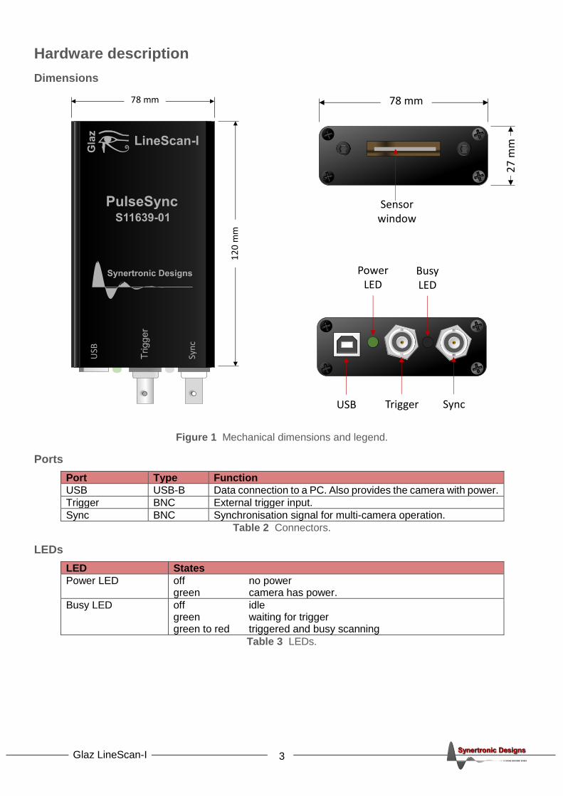
Cameras are connected to a PC via USB interfaces. Glaz LineScan-I cameras are USB 2.0 high-speed devices, but are backwards compatible with USB 1.1 interfaces. USB 1.1 interfaces have a maximum data transfer rate to less than 0.5 MB/s and will limit maximum scan rate of the camera.
If a PC has a limited number of USB ports, it is possible to use an external USB hub. Up to two cameras can be connected to a single USB 2.0 hub without significant reduction in the data transfer rate. It is possible to connect more than two cameras to a single USB 2.0 hub, but this can reduce the maximum data transfer rate and scan rate. When connecting more than two cameras to a single USB hub, it is advisable to use a USB 3.0 hub.
Camera clock speed
The internal sensor clock of the camera can be operated at two frequencies: half-speed and full-speed. The sensor noise level at full-speed is approximately 20% higher compared to the noise level at half-speed. By default, the camera uses the full-speed clock. When low-noise measurements are a priority, it is advisable to use the half-speed clock.
Clock speed Internally sensor pixel clock
half-speed 10 MHz
full-speed 5 MHz
Table 4 Sensor pixel clock.
Triggering cameras
Cameras can be triggered either internally or externally. When running in internal trigger mode, no external trigger should be connected to the camera. In this mode, the trigger signal is generated internally by the camera itself. The frequency of the internal trigger signal depends on the firmware flavour. See “Internal trigger generator” for more information.
When running in external trigger mode, each scan is started after an external trigger pulse is applied to the trigger port. A delay can be specified between the positive going edge of the trigger pulse and the start of the
sensor integration time. The delay can be specified with a resolution of 0.1 s and can be set between 0 and
200 ms. When a delayed trigger4 is received while the camera is busy, this trigger will be ignored.
Integration time
During the integration time, the photo-current from the CMOS sensors will be integrated. The integration time
can be set between 2 and 2000 s. For short-pulse laser applications, the preferred integration time is 5 s.
Figure 3 Single-camera configuration.
4 The delayed trigger is the external trigger signal with the specified delay.
USB
Trigger
6 Glaz LineScan-I
Single-camera configuration
In a single-camera configuration only a single camera is used. When external trigger mode is used, the camera must be provided with a trigger signal via the Trigger port.
In internal trigger mode, leave the Trigger port unconnected. The Sync port must always be left unconnected.
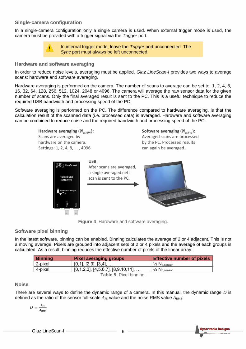
Hardware and software averaging
In order to reduce noise levels, averaging must be applied. Glaz LineScan-I provides two ways to average scans: hardware and software averaging.
Hardware averaging is performed on the camera. The number of scans to average can be set to: 1, 2, 4, 8, 16, 32, 64, 128, 256, 512, 1024, 2048 or 4096. The camera will average the raw sensor data for the given number of scans. Only the final averaged result is sent to the PC. This is a useful technique to reduce the required USB bandwidth and processing speed of the PC.
Software averaging is performed on the PC. The difference compared to hardware averaging, is that the calculation result of the scanned data (i.e. processed data) is averaged. Hardware and software averaging can be combined to reduce noise and the required bandwidth and processing speed of the PC.
Figure 4 Hardware and software averaging.
Software pixel binning
In the latest software, binning can be enabled. Binning calculates the average of 2 or 4 adjacent. This is not a moving average. Pixels are grouped into adjacent sets of 2 or 4 pixels and the average of each groups is calculated. As a result, binning reduces the effective number of pixels of the linear array:
Binning Pixel averaging groups Effective number of pixels
2-pixel [0,1], [2,3], [3,4], … ½ Np,sensor
4-pixel [0,1,2,3], [4,5,6,7], [8,9,10,11], … ¼ Np,sensor
Table 5 Pixel binning.
Noise
There are several ways to define the dynamic range of a camera. In this manual, the dynamic range D is defined as the ratio of the sensor full-scale AFS value and the noise RMS value ARMS:
𝐷 =𝐴FS
𝐴RMS
Hardware averaging (Na,HW):Scans are averaged by hardware on the camera.Settings: 1, 2, 4, 8, ... , 4096
USB:After scans are averaged, a single averaged nett scan is sent to the PC.
Software averaging (Na,SW):Averaged scans are processed by the PC. Processed results can again be averaged.
7 Glaz LineScan-I
In order to decrease the noise level and increase the dynamic range, averaging can be used. The RMS noise level of an averaged signal is reduced by the square root of the number of averaged scans:
𝐴avg,RMS =𝐴RMS
√𝑁a , where Na is the number of averaged scans.
Pixel binning further reduces the noise level:
𝐴avg,binning,RMS =𝐴avg,RMS
√𝑁b , where Nb is the level if binning (e.g. 2 or 4).
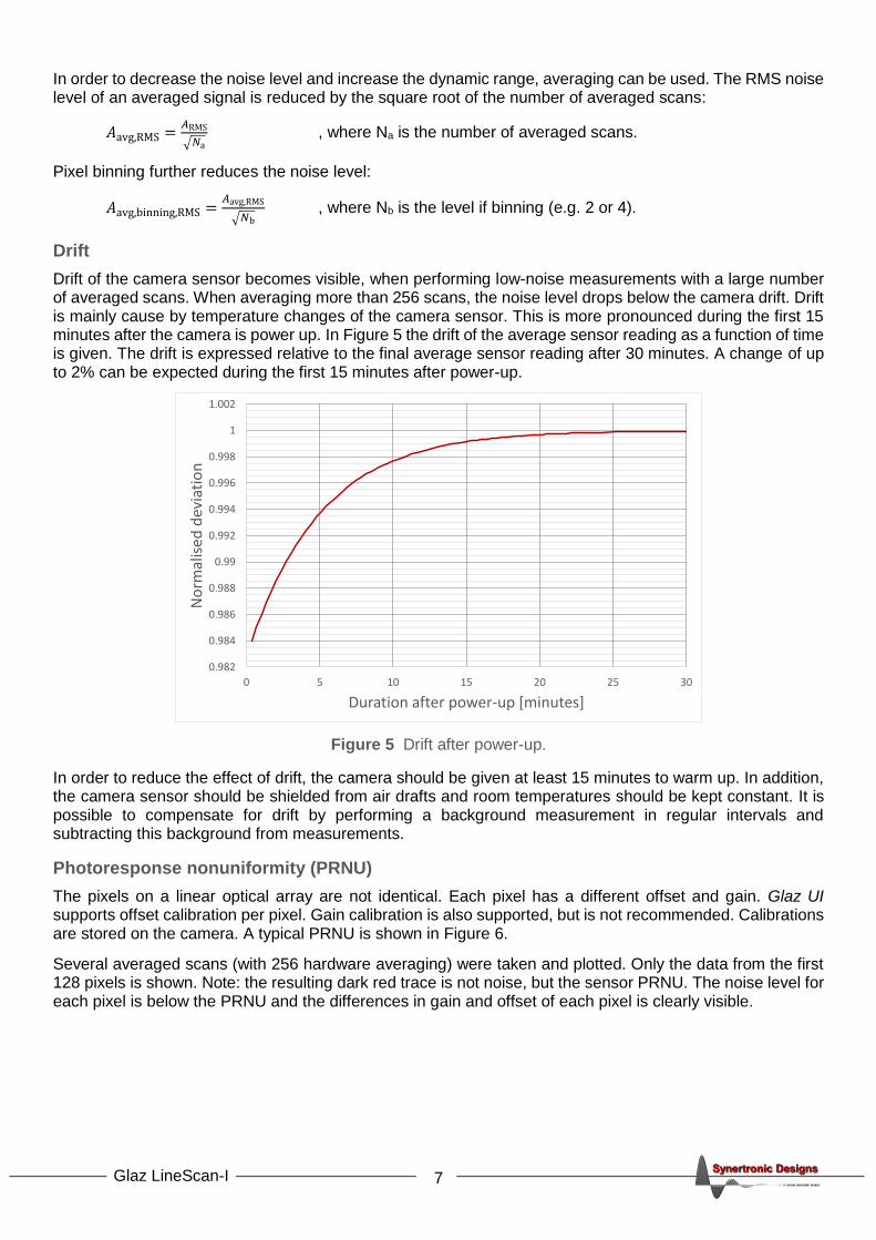
Drift
Drift of the camera sensor becomes visible, when performing low-noise measurements with a large number of averaged scans. When averaging more than 256 scans, the noise level drops below the camera drift. Drift is mainly cause by temperature changes of the camera sensor. This is more pronounced during the first 15 minutes after the camera is power up. In Figure 5 the drift of the average sensor reading as a function of time is given. The drift is expressed relative to the final average sensor reading after 30 minutes. A change of up to 2% can be expected during the first 15 minutes after power-up.
Figure 5 Drift after power-up.
In order to reduce the effect of drift, the camera should be given at least 15 minutes to warm up. In addition, the camera sensor should be shielded from air drafts and room temperatures should be kept constant. It is possible to compensate for drift by performing a background measurement in regular intervals and subtracting this background from measurements.
Photoresponse nonuniformity (PRNU)
The pixels on a linear optical array are not identical. Each pixel has a different offset and gain. Glaz UI supports offset calibration per pixel. Gain calibration is also supported, but is not recommended. Calibrations are stored on the camera. A typical PRNU is shown in Figure 6.
Several averaged scans (with 256 hardware averaging) were taken and plotted. Only the data from the first 128 pixels is shown. Note: the resulting dark red trace is not noise, but the sensor PRNU. The noise level for each pixel is below the PRNU and the differences in gain and offset of each pixel is clearly visible.
0.982
0.984
0.986
0.988
0.99
0.992
0.994
0.996
0.998
1
1.002
0 5 10 15 20 25 30
No
rmal
ised
dev
iati
on
Duration after power-up [minutes]

8 Glaz LineScan-I
Figure 6 Example of PRNU.
2700
2710
2720
2730
2740
2750
2760
2770
2780
2790
2800
0 32 64 96 128
Pix
el v
alu
e
Pixel index
9 Glaz LineScan-I
PulseSync and TimeFill firmware
Instead of providing a general solution, the Glaz LineScan-I cameras are pre-programmed with application-specific firmware. The most notable differences between different firmware flavours are:
• Sensor read-out scheme
• Sync port functions
• Internal trigger generator
LineScan-II cameras provide more flexibility. They can be configured at run-time with either the PulseSync or TimeFill mode.
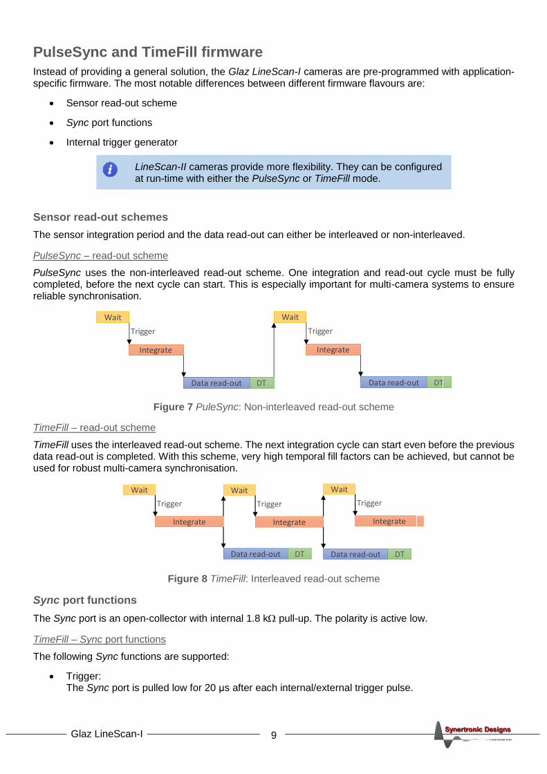
Sensor read-out schemes
The sensor integration period and the data read-out can either be interleaved or non-interleaved.
PulseSync – read-out scheme
PulseSync uses the non-interleaved read-out scheme. One integration and read-out cycle must be fully completed, before the next cycle can start. This is especially important for multi-camera systems to ensure reliable synchronisation.
Figure 7 PuleSync: Non-interleaved read-out scheme
TimeFill – read-out scheme
TimeFill uses the interleaved read-out scheme. The next integration cycle can start even before the previous data read-out is completed. With this scheme, very high temporal fill factors can be achieved, but cannot be used for robust multi-camera synchronisation.
Figure 8 TimeFill: Interleaved read-out scheme
Sync port functions
The Sync port is an open-collector with internal 1.8 k pull-up. The polarity is active low.
TimeFill – Sync port functions
The following Sync functions are supported:
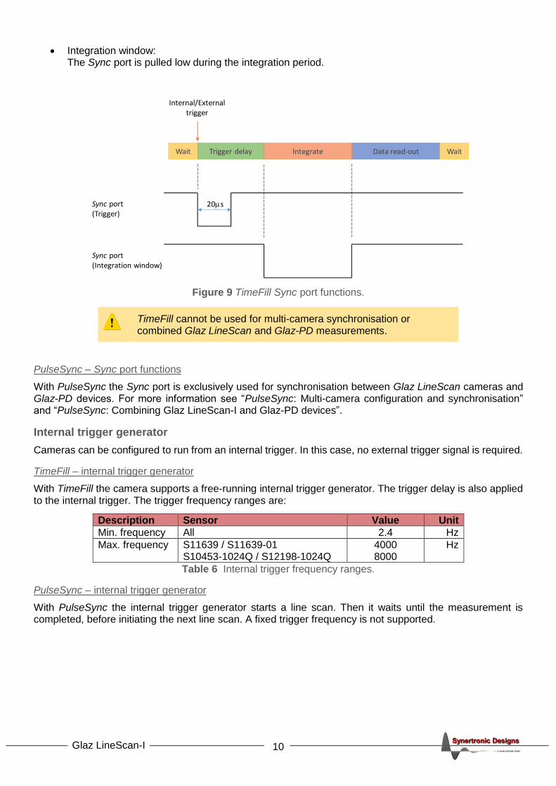
• Trigger: The Sync port is pulled low for 20 μs after each internal/external trigger pulse.
Data read-out DT
Integrate
Wait
Trigger
Data read-out DT
Integrate
Wait
Trigger
Data read-out DT
Integrate
Wait
Trigger
Data read-out DT
Integrate
Wait
Trigger
Integrate
Wait
Trigger
10 Glaz LineScan-I
• Integration window: The Sync port is pulled low during the integration period.
Figure 9 TimeFill Sync port functions.
TimeFill cannot be used for multi-camera synchronisation or combined Glaz LineScan and Glaz-PD measurements.
PulseSync – Sync port functions
With PulseSync the Sync port is exclusively used for synchronisation between Glaz LineScan cameras and Glaz-PD devices. For more information see “PulseSync: Multi-camera configuration and synchronisation” and “PulseSync: Combining Glaz LineScan-I and Glaz-PD devices”.
Internal trigger generator
Cameras can be configured to run from an internal trigger. In this case, no external trigger signal is required.
TimeFill – internal trigger generator
With TimeFill the camera supports a free-running internal trigger generator. The trigger delay is also applied to the internal trigger. The trigger frequency ranges are:
Description Sensor Value Unit
Min. frequency All 2.4 Hz
Max. frequency S11639 / S11639-01 S10453-1024Q / S12198-1024Q
4000 8000
Hz
Table 6 Internal trigger frequency ranges.
PulseSync – internal trigger generator
With PulseSync the internal trigger generator starts a line scan. Then it waits until the measurement is completed, before initiating the next line scan. A fixed trigger frequency is not supported.
20sSync port(Trigger)
Internal/Externaltrigger
Sync port(Integration window)
Data read-outIntegrateWait Trigger delay Wait

11 Glaz LineScan-I
Measurements and scripting
Script file structure
The calculations that need to be performed by the PC with the measured data is defined by XML script files. A typical script file is shown in Figure 10.
Figure 10 XML script file.
A script file consists of three sections:
1. Camera definitions: Each camera used for the measurement must be listed here.
2. Pre-processing steps: The pre-processing steps for each camera listed in the camera definitions must be specified.
3. Calculations: Any number of calculations can be specified. Each calculation can use the pre-processed results of one or more cameras.
Measurement data flow
Figure 11 depicts a multi-camera configuration with three cameras, two pre-processing steps for each camera and two calculations. Hardware averaged scans are sent from each camera to the PC via USB. The scans are then passed through the pre-processing steps. Data reception and pre-processing are performed on separate threads for each camera. On a quad-core PC, this would imply that the data from each camera is pre-processed on a separate core.
Figure 11 Measurement data flow.
Pre-processing steps
<!DOCTYPE GlazScript>
<config>
<camera serial="SYBP005010001" number="1" master="1"/>
<preprocessor camera="1" type="calibrate"/>
<preprocessor camera="1" type="subtract_background"/>
<calculation name="Camera 1" keepscans="1">
<measurement camera="1"/>
</calculation>
</config>
Camera definitions
Calculations
Preprocessor
1 2 3
Preprocessor Preprocessor
Preprocessor Preprocessor Preprocessor
Calculation Calculation
Hardwareaveraging
Na,HW
Softwareaveraging
Na,SW
Total averagingNa,HW x Na,SW

12 Glaz LineScan-I
Calculations are performed only when the pre-processed data from all the cameras for a given hardware averaged scan is available. The process of receiving averaged scans and performing pre-processing and calculations is performed Na,SW times. The results of the calculations are accumulated and at the end of the measurement the software average for each calculation is determined.
Scripting – Camera definitions
In order to use cameras, the must first be uniquely identified. Each camera has an entry in the script file using the following format5:
<camera serial="SN" number="NUM" [master="M"] [reverse="R"] [binning="B"]/>
SN : The serial number of a camera is printed onto the back of the camera. The serial number
has 13 digits and has the format: SYPB + device number + device version + instance number. For example: SYPB005010001. A serial number may only be defined once in a script file.
NUM : The camera number that will be assigned to the camera with the given serial number. This
number will be used in the rest of the script file. This must be a unique number in the range [1 .. 1000].
M : Can be one of the following values: 0, 1, true or false. If the value is 1 or true the camera
will be configured as the master camera. The master camera is the camera that must receive the trigger signal. Only one camera may be defined as the master. The default value is 0 or false.
R : Can be one of the following values: 0, 1, true or false. If the value is 1 or true the scan will
be reversed and the data from pixels 0 to 1023 will be processed as pixels 1023 down to 0. The default value is 0 or false.
B : This value specifies the level of binning. It can be one of the following values:
0 no binning (default) 1 2-pixel binning 2 4-pixel binning
Scripting – Pre-processing steps
Each camera in the camera definition section may have its own set of pre-processing steps. The pre-processing steps are executed in the same order as defined in the script file. It is important to specify the pre-processing steps in the correct order. The following pre-processing steps are supported:
• Calibrate: Calibrates the scan data using the calibration stored on the corresponding camera.
• Inverse Fourier transform (IFFT): Calculates the inverse transform of a scan. It is assumed that a scan is performed with constant wavelength increments. The wavelength for each pixel is given by:
𝜆𝑛 = 𝜆min +𝜆min−𝜆max
𝑁−1𝑛 with 𝑛 = 0 . . 1023,
where n is the pixel number and 𝜆min and 𝜆max are the wavelength limits. The wavelength limits are specified outside the script file. In LabView a VI is provided to set the limits and in the stand-alone Glaz UI the limits can be specified on the user interface. The IFFT pre-processor will interpolate the scan in frequency space with constant increments. The IFFT is performed on the interpolated data. It is possible to turn interpolation off, by setting the interpolate attribute to false. In this case, the
IFFT is performed directly on the scan data.
5 Parameters in square brackets […] are optional.
13 Glaz LineScan-I
• Background subtract: Before performing a measurement the background must be measured. In LabView a VI is provided and in the stand-alone Glaz UI an action can be triggered to take a background measurement. Note: The stored background will be the resulting data after pre-processing. The background subtraction must, therefore, always be the last pre-processing step.
A pre-processing step entry in the script file has the following format:
<preprocessor camera="NUM" type="T" [interpolate="I"]/>
NUM : The camera number that was assigned to a camera in the camera definition section. This
pre-processing step will be applied to the scan data from the camera with the given number.
T : Can be one of the following values: calibrate, ifft or background_subtract.
I : This attribute is only applicable to the IFFT pre-processor. It can be one of the following
values: 0, 1, true or false. If the value is 1 or true, the IFFT is performed on the interpolated data. If the value is 0 or false, no interpolation is done and the IFFT is performed directly on the scan data. The default value is 1 or true.
Scripting – Calculations
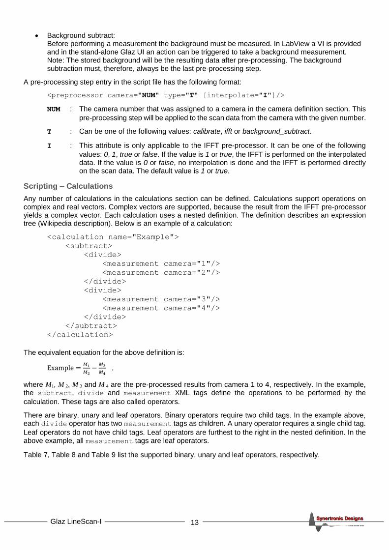
Any number of calculations in the calculations section can be defined. Calculations support operations on complex and real vectors. Complex vectors are supported, because the result from the IFFT pre-processor yields a complex vector. Each calculation uses a nested definition. The definition describes an expression tree (Wikipedia description). Below is an example of a calculation:
<calculation name="Example">
<subtract>
<divide>
<measurement camera="1"/>
<measurement camera="2"/>
</divide>
<divide>
<measurement camera="3"/>
<measurement camera="4"/>
</divide>
</subtract>
</calculation>
The equivalent equation for the above definition is:
Example =𝑀1
𝑀2−
𝑀3
𝑀4 ,
where M1, M 2, M 3 and M 4 are the pre-processed results from camera 1 to 4, respectively. In the example, the subtract, divide and measurement XML tags define the operations to be performed by the
calculation. These tags are also called operators.
There are binary, unary and leaf operators. Binary operators require two child tags. In the example above, each divide operator has two measurement tags as children. A unary operator requires a single child tag.
Leaf operators do not have child tags. Leaf operators are furthest to the right in the nested definition. In the above example, all measurement tags are leaf operators.
Table 7, Table 8 and Table 9 list the supported binary, unary and leaf operators, respectively.

14 Glaz LineScan-I
Operation Scalar-Scalar (s1, s2) Scalar-Vector (s, v) Vector-Vector (v1, v2)
Multiplication 𝑠1 ∙ 𝑠2 𝑣𝑛 ∙ 𝑠 or 𝑠 ∙ 𝑣𝑛, 𝑛 = 0. . 𝑁 𝑣1,𝑛 ∙ 𝑣2,𝑛, 𝑛 = 0. . 𝑁
Division 𝑠1/𝑠2 𝑣𝑛/𝑠, 𝑛 = 0. . 𝑁 𝑣1,𝑛/𝑣2,𝑛, 𝑛 = 0. . 𝑁
Addition 𝑠1 + 𝑠2 𝑣𝑛 + 𝑠 or 𝑠 + 𝑣𝑛, 𝑛 = 0. . 𝑁 𝑣1,𝑛 + 𝑣2,𝑛, 𝑛 = 0. . 𝑁
Subtraction 𝑠1 − 𝑠2 𝑣𝑛 − 𝑠, 𝑛 = 0. . 𝑁 𝑣1,𝑛 − 𝑣2,𝑛, 𝑛 = 0. . 𝑁
Table 7 Binary operators.
Operation Scalar (s) Vector (v)
Magnitude Not supported |𝑣𝑛|, 𝑛 = 0. . 𝑁
Phase Not supported 𝑣�̂�, 𝑛 = 0. . 𝑁
Table 8 Unary operators.
Operation Result
Measurement Returns the data of a given camera. The data is returned as a vector containing the 1024 values of the last pre-processed scan. If the IFFT pre-processor is used, the vector will contain complex values.
Scalar Defines a single real, scalar value.
Table 9 Leaf operators.
Calculation definition start
A calculation and its definition starts with a calculation entry. A calculation entry in the script file has the following format:
<calculation [name="NAME"] [keepscans="K"]>
… (operations)
</calculation>
NAME : The name of the calculation. In the Glaz UI this will be displayed in the legend of the
measurement plot.
K : Can be one of the following values: 0, 1, true or false. If the value is 1 or true each hardware
averaged scan is saved and can be viewed in the Glaz UI. The default value is 0 or false.
The operations of a calculation are described by a nested definition using the operators summarised in Table 7, Table 8 and Table 9. See the sections below for more information on operators.
The calculation entry must only contain a single operator. This can either be a binary, unary or leaf operator.
After receiving the pre-processed data from each camera, the calculations are performed. The result of each calculation is accumulated and an average is calculated (see “Hardware and software averaging”). It is assumed, that the result is real. If the result contains complex values, the imaginary part will be ignored.
Binary operators
All binary operators have the following format:
<OP>
<…> (first child operator)
<…> (second child operator) </OP>
OP : Can be one of the following values: add, subtract, multiply or divide.
The function of the first and second child operators are described in the table below:

15 Glaz LineScan-I
Operation First child operator Second child operator
Add term 1 + term 2
Subtract minuend - subtrahend
Multiply factor 1 ∙ factor 2
Divide numerator / denominator
Table 10 Child tags of binary operators.
Unary operators
All unary operators have the following format:
<OP>
<…> (child operator) </OP>
OP : Can be one of the following values: magnitude or phase.
The magnitude or phase is calculated from the data defined by the child operator.
The phase operator supports phase unwrapping. The algorithm for unwrapping the phase uses a threshold value. If the difference in phase between two successive data points is larger than the threshold value, then
2 will be added or subtracted from the next data point. The threshold value can be tweaked with the threshold attribute:
<phase [threshold="T"]>
T : A decimal number specifying the threshold as a faction of 2. The default value is 0.75. For
T > 1.0, phase unwrapping will be disabled.
Leaf operators
Tree leaf operators are supported: scalar, measurement and reference. The scalar operator has the following format:
<scalar value="V"/>
V : A decimal number. This is the return value of the scalar operator.
The measurement operator returns the pre-processed scan result of a camera. It has the following format:
<measurement camera="NUM" [ifft="IFFT"] [interpolate="I"]/>
NUM : The camera number that was assigned to a camera in the camera definition section. The
operator will return the pre-processed data for the given camera.
IFFT : Can be one of the following values: 0, 1, true or false. When not specified, the default value
is false. If the value is 1 or true the operator will return the inverse Fourier transform (IFFT) of the pre-processed scan result. This function is useful when both IFFT and non-IFFT results are required. Note: this method is less efficient, than using the IFFT pre-processor.
I : Can be one of the following values: 0, 1, true or false. If the value is 1 or true, the IFFT is
performed on the interpolated data. If the value is 0 or false, no interpolation is done and the IFFT is performed directly on the scan data. The default value is 1 or true.
The reference operator is used to access the result of another calculation. This is necessary when gated calculations need to be combined into a higher-level calculation. It has the following format:
<reference calculation="CALC"/>
CALC : The name of a previously defined calculation (see “Calculation definition start”). The
operator will return result of the referenced calculation.
16 Glaz LineScan-I
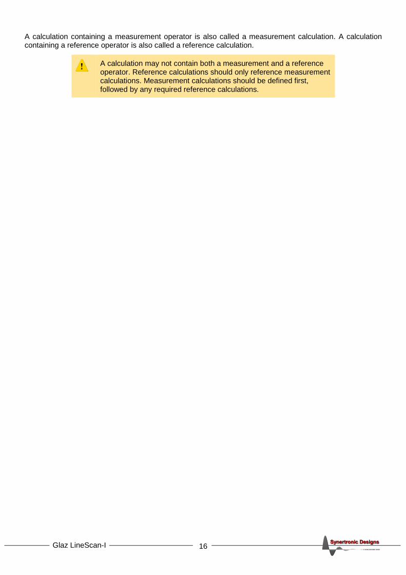
A calculation containing a measurement operator is also called a measurement calculation. A calculation containing a reference operator is also called a reference calculation.
A calculation may not contain both a measurement and a reference operator. Reference calculations should only reference measurement calculations. Measurement calculations should be defined first, followed by any required reference calculations.

17 Glaz LineScan-I
PulseSync: Multi-camera configuration and synchronisation
The Glaz LineScan-I with PulseSync was designed to support multi-camera operation. The design ensures that cameras remain synchronised and that they take scans at the same time. To achieve synchronisation, all the Sync ports of a multi-camera configuration must be connected together. Each camera is connected to a separate USB port on the PC or USB hub.
Figure 12 Multi-camera configuration with three cameras.
Figure 13 PulseSync synchronisation via the Sync port.
At least one camera must be defined as the Master. The Master receives the external trigger signal or generates the internal trigger signal. After the configured trigger delay, the Master pulls the Sync port low. This initiates the integration period on all connected cameras. Each camera pulls the Sync port low during the integration and data read-out period. The Sync port is released only after all the cameras have completed the data read-out. As long as any one of the cameras are busy with a scan or are sending data to a PC, the the Sync signal will remain asserted low.
USB
USBUSB
SyncSync
Trigger
Slave Slave Master
Sync port
Internal/Externaltrigger
Data read-outIntegrate
Wait Trigger delay WaitMaster cameratrigger handler
Wait Wait
Master pullsSync low
Data read-outIntegrateWait Wait
Camera 1
Camera 2
Sync falling edgestarts integration
on all cameras
Camera 1 pullsSync low
Camera 2 pullsSync low
Camera 1releases Sync
Camera 2releases Sync

18 Glaz LineScan-I
If triggered internally, leave the Trigger port unconnected. The Trigger port of all slave cameras must be left unconnected.
When a delayed trigger signal is received by the master camera, while the Sync signal is asserted, this trigger will be ignored. A multi-camera configuration will remain synchronised, even if the trigger frequency is higher than the processing speed of the cameras and PC. If the trigger frequency is higher than system’s processing speed, some of the triggers will be ignored. Important to note, that all cameras will ignore the same trigger signal. It is safe to use a multi-camera configuration with USB 1.1 interfaces, USB 2.0 hubs or with slower PCs. The only side-effect will be a lower achievable scan rate and measurements can take longer.
19 Glaz LineScan-I
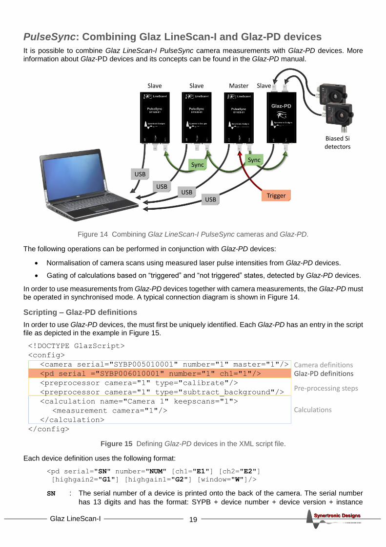
PulseSync: Combining Glaz LineScan-I and Glaz-PD devices
It is possible to combine Glaz LineScan-I PulseSync camera measurements with Glaz-PD devices. More information about Glaz-PD devices and its concepts can be found in the Glaz-PD manual.
Figure 14 Combining Glaz LineScan-I PulseSync cameras and Glaz-PD.
The following operations can be performed in conjunction with Glaz-PD devices:
• Normalisation of camera scans using measured laser pulse intensities from Glaz-PD devices.
• Gating of calculations based on “triggered” and “not triggered” states, detected by Glaz-PD devices.
In order to use measurements from Glaz-PD devices together with camera measurements, the Glaz-PD must be operated in synchronised mode. A typical connection diagram is shown in Figure 14.
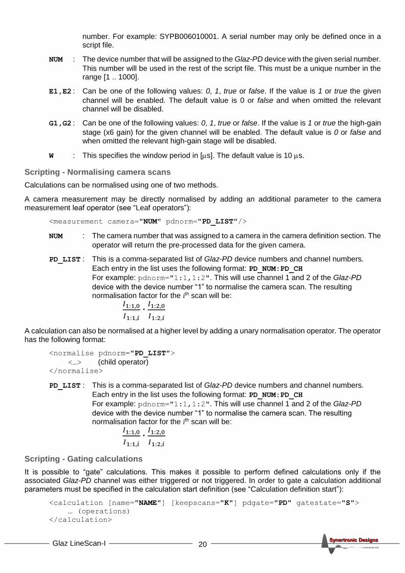
Scripting – Glaz-PD definitions
In order to use Glaz-PD devices, the must first be uniquely identified. Each Glaz-PD has an entry in the script file as depicted in the example in Figure 15.
Figure 15 Defining Glaz-PD devices in the XML script file.
Each device definition uses the following format:
<pd serial="SN" number="NUM" [ch1="E1"] [ch2="E2"]
[highgain2="G1"] [highgain1="G2"] [window="W"]/>
SN : The serial number of a device is printed onto the back of the camera. The serial number
has 13 digits and has the format: SYPB + device number + device version + instance
USB
USBUSB
SyncSync
Trigger
Slave Slave Master Slave
PD
USB
Biased Sidetectors
<!DOCTYPE GlazScript>
<config>
<camera serial="SYBP005010001" number="1" master="1"/>
<pd serial ="SYBP006010001" number="1" ch1="1"/>
<preprocessor camera="1" type="calibrate"/>
<preprocessor camera="1" type="subtract_background"/>
<calculation name="Camera 1" keepscans="1">
<measurement camera="1"/>
</calculation>
</config>
Glaz-PD definitions
20 Glaz LineScan-I
number. For example: SYPB006010001. A serial number may only be defined once in a script file.
NUM : The device number that will be assigned to the Glaz-PD device with the given serial number.
This number will be used in the rest of the script file. This must be a unique number in the range [1 .. 1000].
E1,E2 : Can be one of the following values: 0, 1, true or false. If the value is 1 or true the given
channel will be enabled. The default value is 0 or false and when omitted the relevant channel will be disabled.
G1,G2 : Can be one of the following values: 0, 1, true or false. If the value is 1 or true the high-gain
stage (x6 gain) for the given channel will be enabled. The default value is 0 or false and when omitted the relevant high-gain stage will be disabled.
W : This specifies the window period in [s]. The default value is 10 s.
Scripting - Normalising camera scans
Calculations can be normalised using one of two methods.
A camera measurement may be directly normalised by adding an additional parameter to the camera measurement leaf operator (see “Leaf operators”):
<measurement camera="NUM" pdnorm="PD_LIST"/>
NUM : The camera number that was assigned to a camera in the camera definition section. The
operator will return the pre-processed data for the given camera.
PD_LIST : This is a comma-separated list of Glaz-PD device numbers and channel numbers.
Each entry in the list uses the following format: PD_NUM:PD_CH
For example: pdnorm="1:1,1:2". This will use channel 1 and 2 of the Glaz-PD
device with the device number “1” to normalise the camera scan. The resulting normalisation factor for the ith scan will be:
𝐼1:1,0
𝐼1:1,𝑖∙
𝐼1:2,0
𝐼1:2,𝑖
A calculation can also be normalised at a higher level by adding a unary normalisation operator. The operator has the following format:
<normalise pdnorm="PD_LIST">
<…> (child operator) </normalise>
PD_LIST : This is a comma-separated list of Glaz-PD device numbers and channel numbers.
Each entry in the list uses the following format: PD_NUM:PD_CH
For example: pdnorm="1:1,1:2". This will use channel 1 and 2 of the Glaz-PD
device with the device number “1” to normalise the camera scan. The resulting normalisation factor for the ith scan will be:
𝐼1:1,0
𝐼1:1,𝑖∙
𝐼1:2,0
𝐼1:2,𝑖
Scripting - Gating calculations
It is possible to “gate” calculations. This makes it possible to perform defined calculations only if the associated Glaz-PD channel was either triggered or not triggered. In order to gate a calculation additional parameters must be specified in the calculation start definition (see “Calculation definition start”):
<calculation [name="NAME"] [keepscans="K"] pdgate="PD" gatestate="S">
… (operations)
</calculation>

21 Glaz LineScan-I
NAME : The name of the calculation. In the Glaz UI this will be displayed in the legend of the
measurement plot.
K : Can be one of the following values: 0, 1, true or false. If the value is 1 or true each hardware
averaged scan is saved and can be viewed in the Glaz UI. The default value is 0 or false.
PD : This is only one entry, instead of a list, defining the Glaz-PD device number and channel
number. The entry uses the following format: PD_NUM:PD_CH
For example: pdgate="1:2". This will use channel 2 of the Glaz-PD device with the
device number “1”.
S : Can be one of the following values: 0, 1, true or false. If the value is 1 or true the calculation
will be performed and accumulated only when the associated Glaz-PD channel was triggered. If the value is 0 or false the calculation will be performed and accumulated only when the associated Glaz-PD channel was not triggered.
When keepscans is enabled for a gated calculation all scans are
kept, even scans for which the calculation was not performed. When a calculation is not performed due to gating, that kept scan will be all zeros.
Error detection
A measurement will be terminated if a digitized value from a Glaz-PD was expected, but that channel was not triggered. This will happen if a camera scan needs to be normalised, but the channel used for the normalisation was not triggered during the specified Glaz-PD window period.

22 Glaz LineScan-I
Glaz UI
Glaz UI is a stand-alone user interface to configure and take measurements with Glaz LineScan-I cameras. It is also a useful tool to test camera performance and script files.
Installing Glaz UI
The installer for Glaz UI can be downloaded from the Synertronic Designs web page. Download and run the installer.
If the target PC is not connected to the internet, it is advisable to pre-install the USB device driver. The USB device driver can be downloaded from the Synertronic Designs web page.
Home page
When starting the application, the Home page is displayed. The application can be used in several modes:
• Single device Use this mode to connect with a single device. This is a quick way to do basic measurements, test device functions and perform calibrations.
• Run script This mode requires a script file and can be used to test scripts and perform more complex multi-camera measurements.
• Application This mode offers several application-specific extensions. See the application-specific documentation on the Synertronic Designs web page.
Single device mode

23 Glaz LineScan-I
1. Select the Home page.
2. Select Single device mode.
3. Select the Glaz-PD device in the Devices drop-down.
4. Click Connect.
After successfully connecting to a device, a Measurements tab is added. Click on the Measurements tab to switch to the measurement page.
Measurements page (Single device)
Acquisition tab
There are several Acquisition parameters that can be set and are grouped into Trigger settings and Measurement settings.
The following Trigger settings are provided:
• Trigger source Select either External or Internal trigger. See “Triggering cameras” for more information.

24 Glaz LineScan-I
• Internal trigger [Hz] Set the internal trigger frequency. This is only supported for TimeFill cameras. See “Triggering cameras” for more information.
• Trigger delay [us] Set the trigger delay in μs. See “Triggering cameras” for more information.
The following Measurement settings are provided:
• Sensor clock speed Set the internal pixel clock speed of the camera. See “Camera clock speed” for more information.
• Hardware averaging Set the number of scans for hardware averaging. See “Hardware and software averaging" for more information.
• Integration time [us] Specify the integration time of the camera in μs. See “Integration time” for more information.
• Binning Sets the level of pixel binning. See “Software pixel binning” for more information.
• Use calibration When checked, the calibration stored on the camera will be used to compensate for offset and gain differences. See “Photoresponse nonuniformity (PRNU)” for more information. When unchecked, no calibration will be used.
• Loop When unchecked, the application will only take one measurement when
clicking the button. When checked, the application will keep taking
measurements, until the button is clicked.
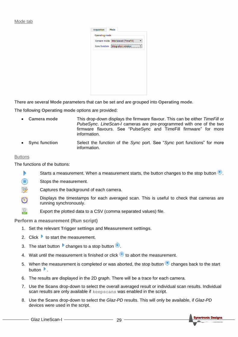
Mode tab
There are several Mode parameters that can be set and are grouped into Operating mode.
The following Operating mode options are provided:
• Camera mode This drop-down displays the firmware flavour. This can be either TimeFill or PulseSync. LineScan-I cameras are pre-programmed with one of the two firmware flavours. See “PulseSync and TimeFill firmware” for more information.
• Sync function Select the function of the Sync port. See “Sync port functions” for more information.
25 Glaz LineScan-I
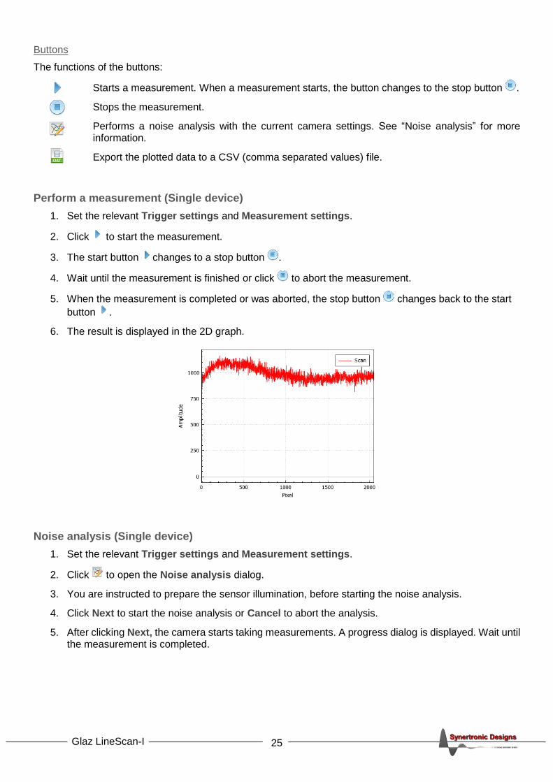
Buttons
The functions of the buttons:
Starts a measurement. When a measurement starts, the button changes to the stop button .
Stops the measurement.
Performs a noise analysis with the current camera settings. See “Noise analysis” for more information.
Export the plotted data to a CSV (comma separated values) file.
Perform a measurement (Single device)
1. Set the relevant Trigger settings and Measurement settings.
2. Click to start the measurement.
3. The start button changes to a stop button .
4. Wait until the measurement is finished or click to abort the measurement.
5. When the measurement is completed or was aborted, the stop button changes back to the start
button .
6. The result is displayed in the 2D graph.
Noise analysis (Single device)
1. Set the relevant Trigger settings and Measurement settings.
2. Click to open the Noise analysis dialog.
3. You are instructed to prepare the sensor illumination, before starting the noise analysis.
4. Click Next to start the noise analysis or Cancel to abort the analysis.
5. After clicking Next, the camera starts taking measurements. A progress dialog is displayed. Wait until the measurement is completed.

26 Glaz LineScan-I
6. After completing the measurements, the result dialog is displayed:
7. Click in the top right corner of the dialog to close the dialog.
8. Click Finish on the Noise Analysis dialog.
The noise analysis is performed on 100 scans using the current measurement settings. The following results are shown:
• Total noise: A graph of the RMS noise level for each pixel. This RMS noise graph includes the effect of drift.
• Average compensated: A graph of the average compensated RMS noise level for each pixel. To compensate for drift, the average of each scan is subtracted from each pixel reading.
• Total noise PP: A graph of the total peak-peak noise level for each pixel. The noise levels include the effect of drift.
• Average compensated PP: A graph of the average compensated peak-peak noise level for each pixel. To compensate for drift, the average of each scan is subtracted from each pixel reading.
• Average: A graph of the average sensor reading for each of the 100 scans.
• Drift: A graph of the difference of the average of each of the 100 scans relative to the average of the first scan.

27 Glaz LineScan-I
Script mode
1. Select the Home page.
2. Select Run script mode.
3. Select a script file by using one of the following methods:
• Click to open a file dialog to select a script file.
• Type the script file name into the Script file line edit.
• Use the Script file drop-down to select a previously entered script file.
4. Click Open to load the script file.
After successfully loading the selected script, a Script tab is added. Click on the Script tab to switch to the script page.
Script page (Run script)

28 Glaz LineScan-I
Acquisition tab
There are several Acquisition parameters that can be set and are grouped into Trigger settings and Measurement settings.
The following Trigger settings are provided:
• Trigger source Select either External or Internal trigger. See “Triggering cameras” for more information.
• Internal trigger [Hz] Set the internal trigger frequency. This is only supported for TimeFill cameras. See “Triggering cameras” for more information.
• Trigger delay [us] Set the trigger delay in μs. See “Triggering cameras” for more information.
The following Measurement settings are provided:
• Sensor clock speed Set the internal pixel clock speed of the camera. See “Camera clock speed” for more information.
• Hardware averaging Set the number of scans for hardware averaging. See “Hardware and software averaging" for more information.
• Scan count Set the number of scans for software averaging. See “Hardware and software averaging" for more information.
• Integration time [us] Specify the integration time of the camera in μs. See “Integration time” for more information.
• Lambda min [nm] The minimum wavelength. This must be set when using IFFT pre-processors.
• Lambda max [nm] The maximum wavelength. This must be set when using IFFT pre-processors.
• Loop When unchecked, the application will only take one measurement when
clicking the button. When checked, the application will keep taking
measurements, until the button is clicked.
29 Glaz LineScan-I
Mode tab
There are several Mode parameters that can be set and are grouped into Operating mode.
The following Operating mode options are provided:
• Camera mode This drop-down displays the firmware flavour. This can be either TimeFill or PulseSync. LineScan-I cameras are pre-programmed with one of the two firmware flavours. See “PulseSync and TimeFill firmware” for more information.
• Sync function Select the function of the Sync port. See “Sync port functions” for more information.
Buttons
The functions of the buttons:
Starts a measurement. When a measurement starts, the button changes to the stop button .
Stops the measurement.
Captures the background of each camera.
Displays the timestamps for each averaged scan. This is useful to check that cameras are running synchronously.
Export the plotted data to a CSV (comma separated values) file.
Perform a measurement (Run script)
1. Set the relevant Trigger settings and Measurement settings.
2. Click to start the measurement.
3. The start button changes to a stop button .
4. Wait until the measurement is finished or click to abort the measurement.
5. When the measurement is completed or was aborted, the stop button changes back to the start
button .
6. The results are displayed in the 2D graph. There will be a trace for each camera.
7. Use the Scans drop-down to select the overall averaged result or individual scan results. Individual scan results are only available if keepscans was enabled in the script.
8. Use the Scans drop-down to select the Glaz-PD results. This will only be available, if Glaz-PD devices were used in the script.

30 Glaz LineScan-I
Software and firmware updates
Enabling online check for updates
1. Select the Home page.
2. Click to open the Global Settings dialog.
3. In the Updates group, enable or disable Check for updates online. When enabled, Glaz UI will try to connect to the online update repository and download any new software and firmware.
Updating the application
1. When check for online updates is enabled, Glaz UI will try to download the latest software and firmware updates from the online repository of Synertronic Designs.
2. If a new version of Glaz UI is available, the user will be notified.
3. When the application closes, the application will ask if the new version must be installed.
Automatic firmware updates
1. Select Single device on the Home page.
2. Connect to the target device.
3. If new firmware is available, the user will be asked to update the firmware of the connected device. Firmware updates can take between 3 to 5 seconds.
Under no circumstances, disconnect the device during a firmware update. If a firmware update fails due to a power or connection failure, the device must be returned to Synertronic Designs for reprogramming.
Manual firmware updates
1. Select Single device on the Home page.
2. Connect to the target device.
3. Click to open the Global Settings dialog.
31 Glaz LineScan-I
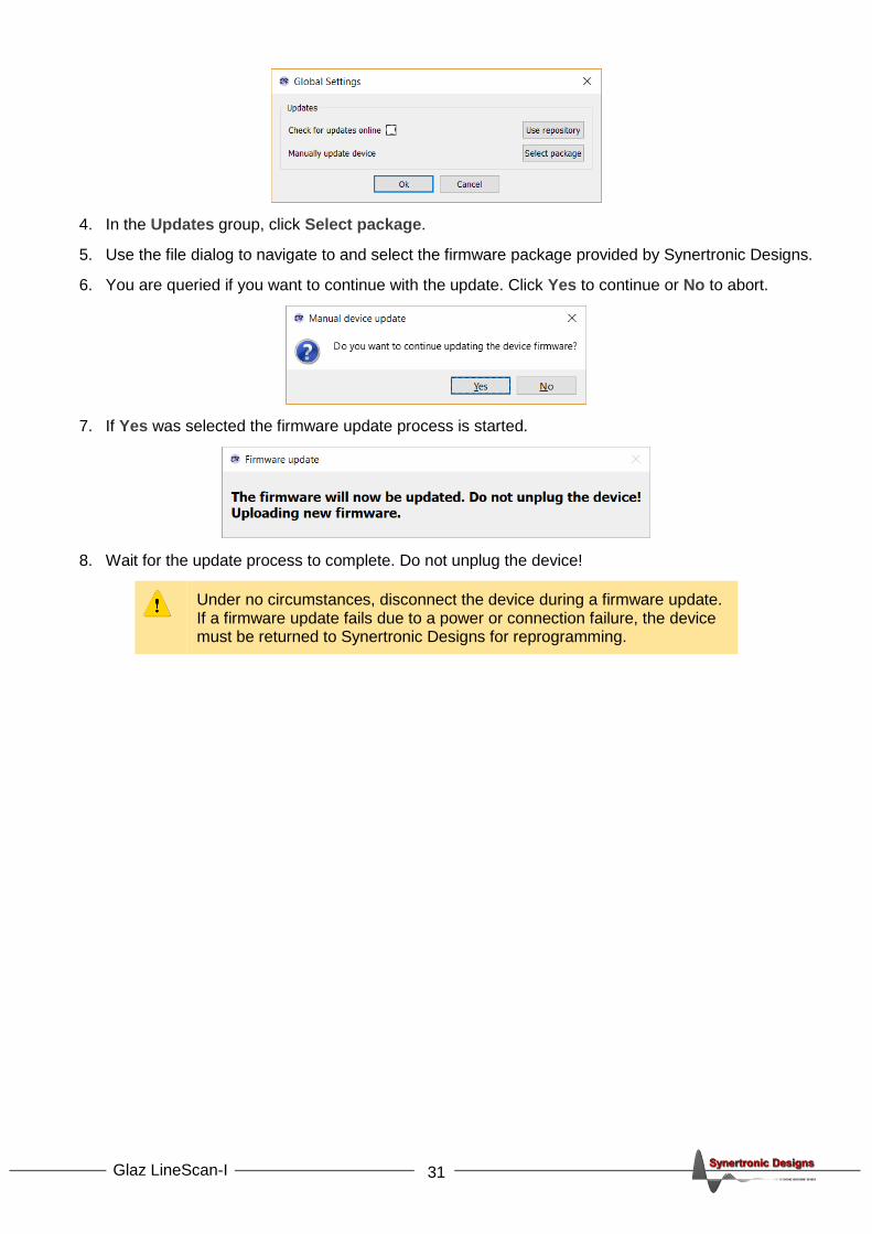
4. In the Updates group, click Select package.
5. Use the file dialog to navigate to and select the firmware package provided by Synertronic Designs.
6. You are queried if you want to continue with the update. Click Yes to continue or No to abort.
7. If Yes was selected the firmware update process is started.
8. Wait for the update process to complete. Do not unplug the device!
Under no circumstances, disconnect the device during a firmware update. If a firmware update fails due to a power or connection failure, the device must be returned to Synertronic Designs for reprogramming.

32 Glaz LineScan-I
LabView integration
Installation
Follow these steps to install the LabView driver:
1. Download GlazLabView.zip 2. Unzip GlazLabView.zip in the user.lib directory of your LabView installation 3. Run LabView 4. Select Tools → Find VIs on Disk…
5. Search the user.lib directory to find the Glaz LabView VIs
The VIs for interfacing with Glaz devices should now be visible in LabView’s Functions palette.
An example showing how to use the Glaz VIs can be found in the */user.lib/GlazLib/example directory.
Usage notes and Error handling
The Glaz LabView integration consists of a set of VIs. Every VI uses the standard LabView error handling technique and each VI has an Error in and Error out parameter. The error parameters are standard LabView error structures, which provide error feedback and flow control.
The following workflow is recommended:
1. Initialise a session using either initialise VI or initialise Single Device VI.
2. Apply settings with the setter VIs.
3. Capture the background (optional, only used when background subtraction is required).
4. Run a measurement.
5. Retrieve and process results.
6. Repeat from either:
• Step 1 and initialise with a new script file.
• Step 2 with new settings.
• Step 4 with the same settings.
7. Close the session by calling the close VI.
33 Glaz LineScan-I
VIs
intialise
Initialise the session with the given scriptFileName. If the session was initialised before, the previous session is closed and disconnects from all previously connected devices.
Parameters:
scriptFileName String (in) File path of the Glaz script file.
Return error codes:
ERROR_NONE No error and initialisation was successful.
ERROR_SCRIPT The specified script was not found or contains an error.
ERROR_CONNECTING_TO_CAMERAS There was an error while connecting to the devices specified in the script file. This can be caused by an USB communication error or the specified device was not found or is busy.
ERROR_INVALID_SETTINGS The script contains an invalid combination of settings and devices.
ERROR_DOWNLOADING_CALIBRATIONS There was an error while downloading the camera calibration from one of the target devices.
initialise Single Device
Initialise the session in single-device mode. If the session was initialised before, the previous session is closed and disconnects from all previously connected devices.
During single-device initialisation the Glaz back-end is initialised with the following script:
<!DOCTYPE GlazScript>"
<config>"
<camera serial=<SN> number="1" master="1"/>
<calculation name="Camera 1" keepscans=<KS>>
<measurement camera="1"/>
</calculation>
</config>
The serial number <SN> and keep-scans <KS> attribute are determined from the singelDeviceType and
keepScans parameters.
Parameters:
singelDeviceType Integer (in) Specifies the type of Glaz LineScan camera. Must be one of the following values (as defined at the top of the header file): GLAZ_LINESCAN_I_PULSESYNC_S10453_SINGLE_DEVICE_TYPE 1 GLAZ_LINESCAN_I_PULSESYNC_S11639_SINGLE_DEVICE_TYPE 2 GLAZ_LINESCAN_I_TIMEFILL_S11639_SINGLE_DEVICE_TYPE 3 GLAZ_LINESCAN_I_SPECTROCAM_S11639_SINGLE_DEVICE_TYPE 4 GLAZ_LINESCAN_II_SINGLE_DEVICE_TYPE 5
Note: LineScan-I PulseSync S10453 was previously called the Glaz-I. LineScan-I TimeFill S11639 was previously called the Glaz-S.
keepScans Boolean (in) When set to true all individual scans (lines) will be stored in memory and can be accessed via the get Scan VI after the run Measurement VI was called.
Return error codes:
ERROR_NONE No error and initialisation was successful.
ERROR_INVALID_SINGLE_DEVICE_TYPE An invalid value was passed for singelDeviceType.

34 Glaz LineScan-I
ERROR_INITIALISING_SINGEL_DEVICE Unknown error while initialising the internal session.
ERROR_CONNECTING_TO_CAMERAS There was an error while connecting to the devices specified in the script file. This can be caused by an USB communication error or the specified device was not found or is busy.
ERROR_INVALID_SETTINGS Unknown error while initialising the internal session.
ERROR_DOWNLOADING_CALIBRATIONS There was an error while downloading the camera calibration from one of the target devices.
close
Closes the script file and disconnects from all cameras.
Always execute this VI at the end of the LabView program.
set Scan Clock Speed
Sets pixel clock scan speed. See “Camera clock speed” for more information.
Restrictions:
Only supported by LineScan-I devices.
Parameters:
speed Integer (in) The clock speed. Default = SCAN_CLOCK_FULL_SPEED. Must be one of the following values: SCAN_CLOCK_FULL_SPEED 0 SCAN_CLOCK_HALF_SPEED 1
Return error codes:
ERROR_NONE No error and settings were applied.
ERROR_NOT_INITIALISED The session was not initialised. First call the initialise VI or initialise Single Device VI.
ERROR_CLOCK_SPEED_UNSUPPORTED Variable clock speed is not supported. It is only supported by LineScan-I devices.
ERROR_INVALID_SCAN_CLOCK_SPEED An invalid clock speed was specified.
set Wavelengths
Sets the minimum and maximum wavelengths. It is important to set these values when using the IFFT pre-processor (see “Scripting – Pre-processing steps” for more information).
Parameters:
lambdaMin Double (in) The minimum wavelength. Default = 1.0. Validation: lambdaMin > 0.0
lambdaMax Double (in) The maximum wavelength. Default = 2.0. Validation: lambdaMax > 0.0 lambdaMax > lambdaMin
Return error codes:

35 Glaz LineScan-I
ERROR_NONE No error and settings were applied.
ERROR_NOT_INITIALISED The session was not initialised. First call the initialise VI or initialise Single Device VI.
ERROR_INVALID_WAVELENGTHS The lambdaMin and/or lambdaMax parameters failed validation.
set Hardware Averaging
Sets the number of scans to use during hardware averaging. This value is also equal to the number of hardware averaged scans Na,HW. See “Hardware and software averaging” for more information.
Restrictions:
The supported levels of hardware averaging are device-dependent.
Parameters:
averaging Integer (in) The hardware averaging level. Default = AVERAGING_X1. Must be one of the following values: AVERAGING_X1 0 AVERAGING_X2 1 AVERAGING_X4 2 AVERAGING_X8 3 AVERAGING_X16 4 AVERAGING_X32 5 AVERAGING_X64 6 AVERAGING_X128 7 AVERAGING_X256 8 AVERAGING_X512 9 AVERAGING_X1024 10 AVERAGING_X2048 11 AVERAGING_X4096 12
Return error codes:
ERROR_NONE No error and settings were applied.
ERROR_NOT_INITIALISED The session was not initialised. First call the initialise VI or initialise Single Device VI.
ERROR_INVALID_AVERAGING The specified hardware averaging level is invalid or not supported.
set Scan Count
Sets the number of hardware average scans to perform. This value is also equal to the number of software averaged scans Na,SW. See “Hardware and software averaging” for more information.
Parameters:
scanCount Integer (in) The number of scans (lines) to be measured during one measurement run. Default = 1. Validation: scanCount > 0 scanCount <= 50000
Return error codes:
ERROR_NONE No error and settings were applied.
ERROR_NOT_INITIALISED The session was not initialised. First call the initialise VI or initialise Single Device VI.
36 Glaz LineScan-I
ERROR_INVALID_SCAN_COUNT The scanCount parameter failed validation.
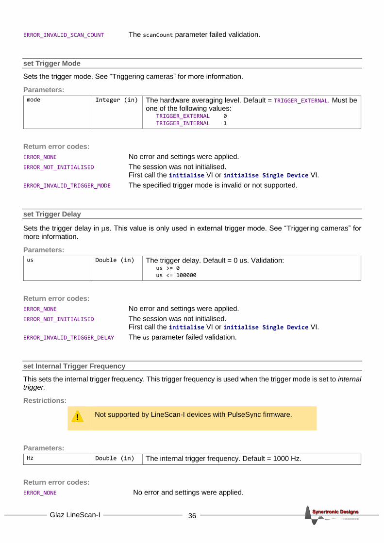
set Trigger Mode
Sets the trigger mode. See “Triggering cameras” for more information.
Parameters:
mode Integer (in) The hardware averaging level. Default = TRIGGER_EXTERNAL. Must be one of the following values: TRIGGER_EXTERNAL 0 TRIGGER_INTERNAL 1
Return error codes:
ERROR_NONE No error and settings were applied.
ERROR_NOT_INITIALISED The session was not initialised. First call the initialise VI or initialise Single Device VI.
ERROR_INVALID_TRIGGER_MODE The specified trigger mode is invalid or not supported.
set Trigger Delay
Sets the trigger delay in s. This value is only used in external trigger mode. See “Triggering cameras” for
more information.
Parameters:
us Double (in) The trigger delay. Default = 0 us. Validation: us >= 0 us <= 100000
Return error codes:
ERROR_NONE No error and settings were applied.
ERROR_NOT_INITIALISED The session was not initialised. First call the initialise VI or initialise Single Device VI.
ERROR_INVALID_TRIGGER_DELAY The us parameter failed validation.
set Internal Trigger Frequency
This sets the internal trigger frequency. This trigger frequency is used when the trigger mode is set to internal trigger.
Restrictions:
Not supported by LineScan-I devices with PulseSync firmware.
Parameters:
Hz Double (in) The internal trigger frequency. Default = 1000 Hz.
Return error codes:
ERROR_NONE No error and settings were applied.
37 Glaz LineScan-I
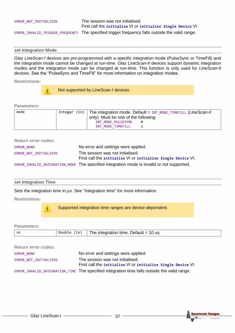
ERROR_NOT_INITIALISED The session was not initialised. First call the initialise VI or initialise Single Device VI.
ERROR_INVALID_TRIGGER_FREQUENCY The specified trigger frequency falls outside the valid range.
set Integration Mode
Glaz LineScan-I devices are pre-programmed with a specific integration mode (PulseSync or TimeFill) and the integration mode cannot be changed at run-time. Glaz LineScan-II devices support dynamic integration modes and the integration mode can be changed at run-time. This function is only used for LineScan-II devices. See the “PulseSync and TimeFill” for more information on integration modes.
Restrictions:
Not supported by LineScan-I devices.
Parameters:
mode Integer (in) The integration mode. Default = INT_MODE_TIMEFILL (LineScan-II only). Must be one of the following: INT_MODE_PULSESYNC 0 INT_MODE_TIMEFILL 1
Return error codes:
ERROR_NONE No error and settings were applied.
ERROR_NOT_INITIALISED The session was not initialised. First call the initialise VI or initialise Single Device VI.
ERROR_INVALID_INTEGRATION_MODE The specified integration mode is invalid or not supported.
set Integration Time
Sets the integration time in s. See “Integration time” for more information.
Restrictions:
Supported integration time ranges are device-dependent.
Parameters:
us Double (in) The integration time. Default = 10 us.
Return error codes:
ERROR_NONE No error and settings were applied.
ERROR_NOT_INITIALISED The session was not initialised. First call the initialise VI or initialise Single Device VI.
ERROR_INVALID_INTEGRATION_TIME The specified integration time falls outside the valid range.

38 Glaz LineScan-I
set Sync Out Mode
Sets the output mode of the Sync port. The supported modes are device-dependent. For devices in PulseSync mode, the Sync output mode is automatically forced to OUT_BUSY. See “Functional description” for more information.
Restrictions:
Not supported by LineScan-I devices with PulseSync firmware. For other devices the supported modes are device-dependent. LineScan-II devices support all modes.
Parameters:
mode Integer (in) The output mode. Default = OUT_INT_WINDOW. Must be one of the following values: OUT_INT_WINDOW 0 OUT_TRIGGER 1 OUT_BUSY 2 OUT_TRIGGER_CYCLE_START 3 OUT_TRIGGER_CYCLE_RUNNING 4 OUT_OFF 5
Return error codes:
ERROR_NONE No error and settings were applied.
ERROR_NOT_INITIALISED The session was not initialised. First call the initialise VI or initialise Single Device VI.
ERROR_INVALID_SYNC_OUT_MODE The specified output mode is invalid or not supported.
set Sync Out Polarity
Sets the output polarity of the Sync port. This functionality is only supported by LineScan-II devices. For devices in PulseSync mode, the Sync output polarity is automatically forced to OUT_POLARITY_ACTIVE_LO. See “Functional description” for more information.
Restrictions:
Only supported by LineScan-II devices.
Parameters:
polarity Integer (in) The output polarity. Default = OUT_POLARITY_ACTIVE_LO. Must be one of the following values: OUT_POLARITY_ACTIVE_HI 1 OUT_POLARITY_ACTIVE_LO 0
Return error codes:
ERROR_NONE No error and settings were applied.
ERROR_NOT_INITIALISED The session was not initialised. First call the initialise VI or initialise Single Device VI.
ERROR_OUT_POLARITY_NOT_SUPPORTED Polarity settings are not supported by the device.
ERROR_INVALID_OUT_POLARITY The specified polarity is not one of the values listed above.
39 Glaz LineScan-I
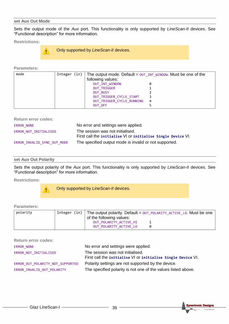
set Aux Out Mode
Sets the output mode of the Aux port. This functionality is only supported by LineScan-II devices. See “Functional description” for more information.
Restrictions:
Only supported by LineScan-II devices.
Parameters:
mode Integer (in) The output mode. Default = OUT_INT_WINDOW. Must be one of the following values: OUT_INT_WINDOW 0 OUT_TRIGGER 1 OUT_BUSY 2 OUT_TRIGGER_CYCLE_START 3 OUT_TRIGGER_CYCLE_RUNNING 4 OUT_OFF 5
Return error codes:
ERROR_NONE No error and settings were applied.
ERROR_NOT_INITIALISED The session was not initialised. First call the initialise VI or initialise Single Device VI.
ERROR_INVALID_SYNC_OUT_MODE The specified output mode is invalid or not supported.
set Aux Out Polarity
Sets the output polarity of the Aux port. This functionality is only supported by LineScan-II devices. See “Functional description” for more information.
Restrictions:
Only supported by LineScan-II devices.
Parameters:
polarity Integer (in) The output polarity. Default = OUT_POLARITY_ACTIVE_LO. Must be one of the following values: OUT_POLARITY_ACTIVE_HI 1 OUT_POLARITY_ACTIVE_LO 0
Return error codes:
ERROR_NONE No error and settings were applied.
ERROR_NOT_INITIALISED The session was not initialised. First call the initialise VI or initialise Single Device VI.
ERROR_OUT_POLARITY_NOT_SUPPORTED Polarity settings are not supported by the device.
ERROR_INVALID_OUT_POLARITY The specified polarity is not one of the values listed above.

40 Glaz LineScan-I
capture Background
Captures the camera background. Subsequent measurements using the background subtract pre-processor, will use the last captured background.
Return error codes:
ERROR_NONE Backgrounds were captured successfully.
ERROR_NOT_INITIALISED The session was not initialised. First call the initialise VI or initialise Single Device VI.
ERROR_CAPTURING_BACKGROUNDS There was a communication error while receiving data from the connected LineScan devices. Check the USB cable connections.
run Measurement
Starts a measurement run. The connected devices will perform a measurement with the previously specified settings. If settings were not specified, the default values are used. This function will only return, when the measurement run is completed, a time-out was encountered or an error was detected. A measurement run is completed after all scanCount number of scans (lines) were captured by the Glaz LineScan devices, the data was received via USB and processed by the back-end.
Return error codes:
ERROR_NONE No error and measurement was run successfully.
ERROR_NOT_INITIALISED The session was not initialised. First call the initialise VI or initialise Single Device VI.
ERROR_INVALID_SETTINGS An invalid combination of settings were specified.
ERROR_RUNNING_MEASUREMENT There was a communication error while receiving data from the connected LineScan devices. Check the USB cable connections.
get Result
Returns a vector with Npixel values containing the software-averaged calculation with the given index. The calculation indices start at zero.
Parameters:
calculationIndex Integer (in) The index of the calculation specified in the Glaz script file. The index is zero-based and depends on the order of calculations defined in the script file. The first calculation in the script file will have calculationIndex = 0, the second calculation will have calculationIndex = 1 and so on. When the session was initialised with the initialise Single Device VI, the only valid value is calculationIndex = 0.
values Double array (out)
Array (vector) with Npixel values containing the averaged data for the calculation with the given index calculationIndex.
Return error codes:
ERROR_NONE No error and values were returned successfully.
ERROR_NOT_INITIALISED The session was not initialised. First call the initialise VI or initialise Single Device VI.
ERROR_INVALID_CALCULATION_INDEX The calculationIndex is out of range. Check the script file and determine the correct index.
ERROR_INVALID_RESULT_DATA_SIZE The array size of the result array values does not match the number of pixels. This is most likely caused if a gated calculation was defined, but
41 Glaz LineScan-I
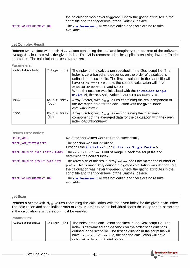
the calculation was never triggered. Check the gating attributes in the script file and the trigger level of the Glaz-PD device.
ERROR_NO_MEASUREMENT_RUN The run Measurement VI was not called and there are no results available.
get Complex Result
Returns two vectors with each Npixel values containing the real and imaginary components of the software-averaged calculation with the given index. This VI is recommended for applications using inverse Fourier transforms. The calculation indices start at zero.
Parameters:
calculationIndex Integer (in) The index of the calculation specified in the Glaz script file. The index is zero-based and depends on the order of calculations defined in the script file. The first calculation in the script file will have calculationIndex = 0, the second calculation will have calculationIndex = 1 and so on. When the session was initialised with the initialise Single Device VI, the only valid value is calculationIndex = 0.
real Double array (out)
Array (vector) with Npixel values containing the real component of the averaged data for the calculation with the given index calculationIndex.
imag Double array (out)
Array (vector) with Npixel values containing the imaginary component of the averaged data for the calculation with the given index calculationIndex.
Return error codes:
ERROR_NONE No error and values were returned successfully.
ERROR_NOT_INITIALISED The session was not initialised. First call the initialise VI or initialise Single Device VI.
ERROR_INVALID_CALCULATION_INDEX The calculationIndex is out of range. Check the script file and determine the correct index.
ERROR_INVALID_RESULT_DATA_SIZE The array size of the result array values does not match the number of pixels. This is most likely caused if a gated calculation was defined, but the calculation was never triggered. Check the gating attributes in the script file and the trigger level of the Glaz-PD device.
ERROR_NO_MEASUREMENT_RUN The run Measurement VI was not called and there are no results available.
get Scan
Returns a vector with Npixel values containing the calculation with the given index for the given scan index. The calculation and scan indices start at zero. In order to obtain individual scans the keepscans parameter
in the calculation start definition must be enabled.
Parameters:
calculationIndex Integer (in) The index of the calculation specified in the Glaz script file. The index is zero-based and depends on the order of calculations defined in the script file. The first calculation in the script file will have calculationIndex = 0, the second calculation will have calculationIndex = 1 and so on.
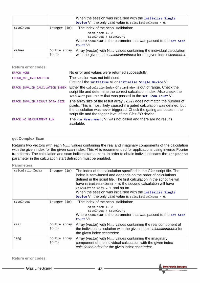
42 Glaz LineScan-I
When the session was initialised with the initialise Single Device VI, the only valid value is calculationIndex = 0.
scanIndex Integer (in) The index of the scan. Validation:
scanIndex >= 0 scanIndex < scanCount
Where scanCount is the parameter that was passed to the set Scan Count VI.
values Double array (out)
Array (vector) with Npixel values containing the individual calculation with the given index calculationIndex for the given index scanIndex.
Return error codes:
ERROR_NONE No error and values were returned successfully.
ERROR_NOT_INITIALISED The session was not initialised. First call the initialise VI or initialise Single Device VI.
ERROR_INVALID_CALCULATION_INDEX Either the calculationIndex or scanIndex is out of range. Check the script file and determine the correct calculation index. Also check the scanCount parameter that was passed to the set Scan Count VI.
ERROR_INVALID_RESULT_DATA_SIZE The array size of the result array values does not match the number of pixels. This is most likely caused if a gated calculation was defined, but the calculation was never triggered. Check the gating attributes in the script file and the trigger level of the Glaz-PD device.
ERROR_NO_MEASUREMENT_RUN The run Measurement VI was not called and there are no results available.
get Complex Scan
Returns two vectors with each Npixel values containing the real and imaginary components of the calculation with the given index for the given scan index. This VI is recommended for applications using inverse Fourier transforms. The calculation and scan indices start at zero. In order to obtain individual scans the keepscans
parameter in the calculation start definition must be enabled.
Parameters:
calculationIndex Integer (in) The index of the calculation specified in the Glaz script file. The index is zero-based and depends on the order of calculations defined in the script file. The first calculation in the script file will have calculationIndex = 0, the second calculation will have calculationIndex = 1 and so on. When the session was initialised with the initialise Single Device VI, the only valid value is calculationIndex = 0.
scanIndex Integer (in) The index of the scan. Validation:
scanIndex >= 0 scanIndex < scanCount
Where scanCount is the parameter that was passed to the set Scan Count VI.
real Double array (out)
Array (vector) with Npixel values containing the real component of the individual calculation with the given index calculationIndex for the given index scanIndex.
imag Double array (out)
Array (vector) with Npixel values containing the imaginary component of the individual calculation with the given index calculationIndex for the given index scanIndex.
Return error codes:

43 Glaz LineScan-I
ERROR_NONE No error and values were returned successfully.
ERROR_NOT_INITIALISED The session was not initialised. First call the initialise VI or initialise Single Device VI.
ERROR_INVALID_CALCULATION_INDEX Either the calculationIndex or scanIndex is out of range. Check the script file and determine the correct calculation index. Also check the scanCount parameter that was passed to the set Scan Count VI.
ERROR_INVALID_RESULT_DATA_SIZE The array size of the result array values does not match the number of pixels. This is most likely caused if a gated calculation was defined, but the calculation was never triggered. Check the gating attributes in the script file and the trigger level of the Glaz-PD device.
ERROR_NO_MEASUREMENT_RUN The run Measurement VI was not called and there are no results available.
get All Scans
Returns a matrix containing all scans for the calculation with the given index. The calculation index starts at zero. The keepscans parameter in the Glaz script file must be enabled.
Parameters:
calculationIndex Integer (in) The index of the calculation specified in the Glaz script file. The index is zero-based and depends on the order of calculations defined in the script file. The first calculation in the script file will have calculationIndex = 0, the second calculation will have calculationIndex = 1 and so on. When the session was initialised with the initialise Single Device VI, the only valid value is calculationIndex = 0.
values Unsigned short 2D matrix (out)
2D Matrix containing all scans for the calculation with the given calculationIndex.
Return error codes:
ERROR_NONE No error and values were returned successfully.
ERROR_NOT_INITIALISED The session was not initialised. First call the initialise VI or initialise Single Device VI.
ERROR_INVALID_CALCULATION_INDEX The calculationIndex is out of range. Check the script file and determine the correct index.
ERROR_INVALID_RESULT_DATA_SIZE The sub-array size of the result array values does not match the number of pixels. This is most likely caused if a gated calculation was defined, but the calculation was never triggered. Check the gating attributes in the script file and the trigger level of the Glaz-PD device.
ERROR_NO_MEASUREMENT_RUN The run Measurement VI was not called and there are no results available.
write All Scans To File
Writes all scans for the calculation with the given index to a binary file. The binary file is written in big-endian format and has the following structure:
uint16 number of scans, Ns uint16 number of pixels, Np (for cameras with the S11639 sensor this will always be 2048) Np x uint16 (1. scan) Np x uint16 (2. scan)

44 Glaz LineScan-I
… Np x uint16 (Ns. scan)
This VI must be called before running a measurement. The scans are written to the target file while the measurement is performed.
Parameters:
calculationIndex Integer (in) The index of the calculation specified in the Glaz script file. The index is zero-based and depends on the order of calculations defined in the script file. The first calculation in the script file will have calculationIndex = 0, the second calculation will have calculationIndex = 1 and so on. When the session was initialised with the initialise Single Device VI, the only valid value is calculationIndex = 0.
filename String (in) File path of the target data file.
Return error codes:
ERROR_NONE No error and settings were applied.
ERROR_NOT_INITIALISED The session was not initialised. First call the initialise VI or initialise Single Device VI.
ERROR_INVALID_CALCULATION_INDEX The calculationIndex is out of range. Check the script file and determine the correct index.
get PD Reference
Returns the reference value used to normalise calculations (see “Scripting” for more information). After the run Measurement VI is called, this will be the first valid received value from a Glaz-PD device.
Parameters:
pdNumber Integer (in) The number specified for a Glaz-PD in the script file (see “Scripting” for more information).
pdChannel Integer (in) One of the following values: 1 Channel 1 2 Channel 2
value Double (out) The value used as reference for the specified channel and the Glaz-PD defined by pdNumber.
Return error codes:
ERROR_NONE No error and values were returned successfully.
ERROR_NOT_INITIALISED The session was not initialised. First call the initialise VI or initialise Single Device VI.
ERROR_INVALID_PD_NUMBER The pdNumber is out of range. Check the script file and determine the correct device number.
ERROR_INVALID_PD_CHANNEL The pdChannel is out of range or the specified channel is not enabled in the script file.

45 Glaz LineScan-I
get PD Values
Returns all the measured values for a given Glaz-PD device and channel. Values which are invalid (i.e. the Glaz-PD device was not triggered) are shown as zero.
Parameters:
pdNumber Integer (in) The number specified for a Glaz-PD in the script file (see “Scripting” for more information).
pdChannel Integer (in) One of the following values: 1 Channel 1 2 Channel 2
count Integer (out) The number of measured values. This should be equal to scanCount as specified via the set Scan Count VI.
value Double (out) Array (vector) with the measured values.
Return error codes:
ERROR_NONE No error and values were returned successfully.
ERROR_NOT_INITIALISED The session was not initialised. First call the initialise VI or initialise Single Device VI.
ERROR_INVALID_PD_NUMBER The pdNumber is out of range. Check the script file and determine the correct device number.
ERROR_INVALID_PD_CHANNEL The pdChannel is out of range or the specified channel is not enabled in the script file.

46 Glaz LineScan-I
Error codes
Code Description Reason
0 ERROR_NONE No error
1 ERROR_NOT_INITIALISED The initialise VI was not executed. First execute the initialise VI with the correct script file, before executing any other Glaz VI.
2 ERROR_SCRIPT There is an error in the script. The error output of the VI contains more information about the error.
3 ERROR_CONNECTING_TO_CAMERAS There is a problem connecting with one or more cameras. Make sure that all cameras are connected and not used by another application. Check that the camera definition section in the script file contains the correct cameras.
4 ERROR_DOWNLOADING_CALIBRATIONS Communication error while trying to download the camera calibration. Check the USB cable connection.
5 ERROR_INVALID_WAVELENGTHS Incorrect wavelength parameters. Check that lambdaMin < lambdaMax and that both lambdaMin and lambdaMax are larger than zero.
6 ERROR_INVALID_AVERAGING averaging parameter is out of range.
7 ERROR_INVALID_SCAN_COUNT scanCount parameter is out of range.
8 ERROR_INVALID_TRIGGER_MODE Trigger mode parameter is out of range.
9 ERROR_INVALID_TRIGGER_DELAY Trigger delay us parameter is out of range.
10 ERROR_INVALID_INTEGRATION_TIME Integration time us parameter is out of range.
11 ERROR_INVALID_SCAN_CLOCK_SPEED Incorrect or unsupported scan clock speed
parameter.
12 ERROR_INVALID_SETTINGS There are some invalid settings. The error output of the VI contains more information about the error.
13 ERROR_CAPTURING_BACKGROUNDS Communication error while trying to capture the camera background. Check the USB cable connection.
14 ERROR_RUNNING_MEASUREMENT Communication error while trying to take a measurement. Check the USB cable connection.
15 ERROR_INVALID_CALCULATION_INDEX Incorrect calculation index was specified. The calculation index starts at zero and must be smaller than the number of calculations specified in the script file.
16 ERROR_INVALID_RESULT_DATA_SIZE The size of the result data is not Npixel. Check that the calculation was specified correctly in the script file.
17 ERROR_INVALID_PD_NUMBER Glaz-PD device number does not match any Glaz-PD device number specified in the Glaz script file.
18 ERROR_INVALID_PD_CHANNEL Glaz-PD channel number may only be 1 or 2.
19 ERROR_INVALID_CAMERA_NUMBER Camera number does match any camera number specified in the Glaz script file.
20 ERROR_INVALID_TRIGGER_FREQUENCY Trigger frequency Hz parameter is out of range
or trigger frequency function is not supported.
21 ERROR_NO_MEASUREMENT_RUN Trying to retrieve results before a measurement was run.
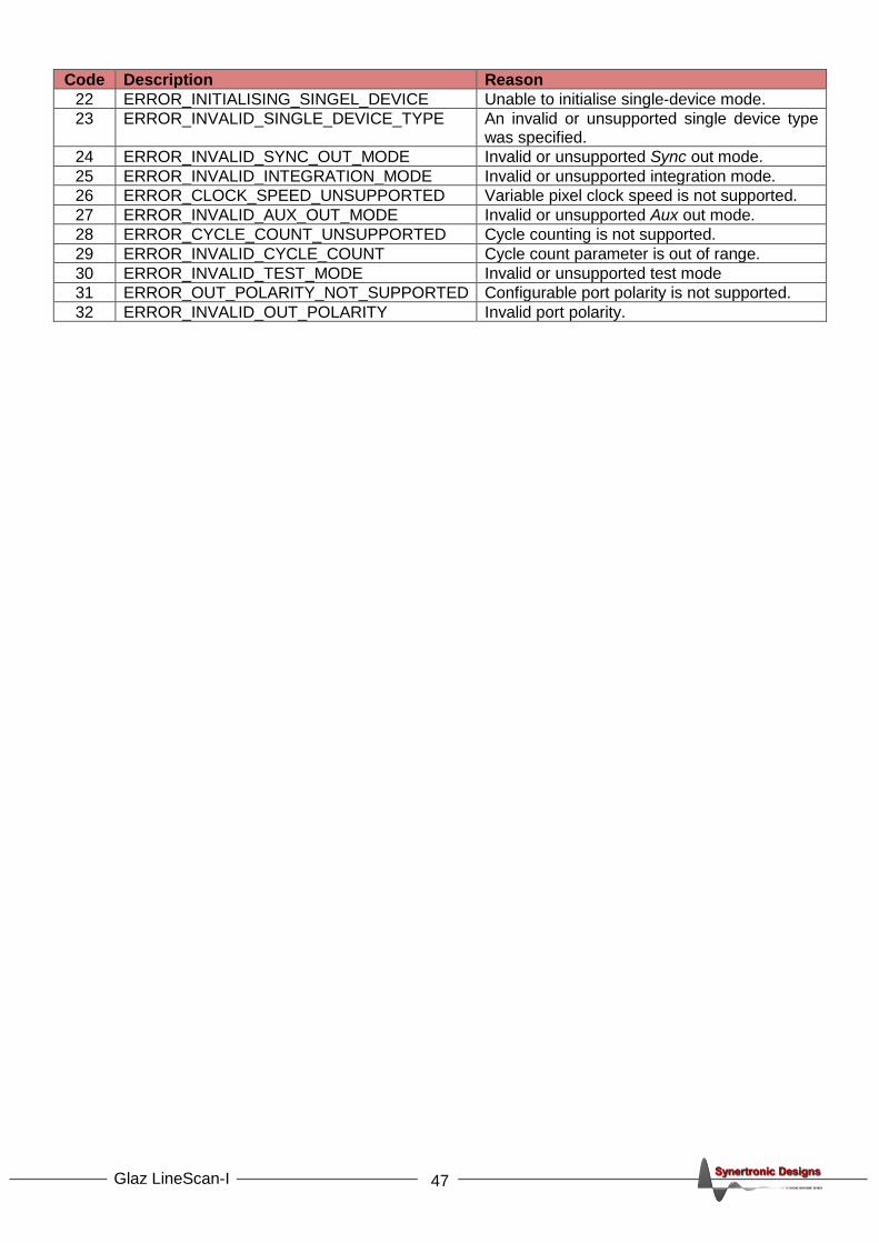
47 Glaz LineScan-I
Code Description Reason
22 ERROR_INITIALISING_SINGEL_DEVICE Unable to initialise single-device mode.
23 ERROR_INVALID_SINGLE_DEVICE_TYPE An invalid or unsupported single device type was specified.
24 ERROR_INVALID_SYNC_OUT_MODE Invalid or unsupported Sync out mode.
25 ERROR_INVALID_INTEGRATION_MODE Invalid or unsupported integration mode.
26 ERROR_CLOCK_SPEED_UNSUPPORTED Variable pixel clock speed is not supported.
27 ERROR_INVALID_AUX_OUT_MODE Invalid or unsupported Aux out mode.
28 ERROR_CYCLE_COUNT_UNSUPPORTED Cycle counting is not supported.
29 ERROR_INVALID_CYCLE_COUNT Cycle count parameter is out of range.
30 ERROR_INVALID_TEST_MODE Invalid or unsupported test mode
31 ERROR_OUT_POLARITY_NOT_SUPPORTED Configurable port polarity is not supported.
32 ERROR_INVALID_OUT_POLARITY Invalid port polarity.

48 Glaz LineScan-I
Examples
In order to get a better understanding of how to compile script files a few examples are presented. The Glaz UI installation contains an example script file for each example discussed below.
The following symbols are used:
• 𝑆𝑛 The measured spectrum from the nth camera.
• 𝐵𝑛 The measured background for the nth camera.
• 𝐼𝑚 The intensity measured by a Glaz-PD device.
• 𝐹𝑘 Functions that need to be calculated.
In each example, a function is presented. The way to compile a script file to calculate this function is shown and how function is mapped onto the script. Mappings are indicated by coloured boxes: Boxes with the same colour in the script and on the function show the equivalent mapping.
All calculations performed by the script are averaged over the specified number of scans (see Hardware and software averaging).
The serial numbers used in the scripts are for illustration only. In a practical set-up, the actual camera serial numbers must be used.
Example 1 – Single camera measurement
𝐹1 = 𝑆1 − 𝐵1
The function simply takes scans with a single camera and subtracts the initially measured background. The script is written as follows:
<!DOCTYPE GlazScript>
<config>
<camera serial="SYBP005010001" number="1" master="1"/>
<preprocessor camera="1" type="subtract_background"/>
<calculation name="F1">
<measurement camera="1"/>
</calculation>
</config>
The function is mapped as follows:
𝐹1 = 𝑆1 − 𝐵1
The blue box represents the pre-processor step in the script. This step already subtracts the background from each camera measurement. The calculation simply returns the camera measurement, which includes the background subtraction.
Example 2 – Ratio of two camera measurements
𝐹2 =𝑆1 − 𝐵1
𝑆2 − 𝐵2− 1
The function simply takes scans from two cameras and subtracts the initially measured backgrounds from each scan. The ratio of the scans (with subtracted backgrounds are then taken). The script is written as follows:
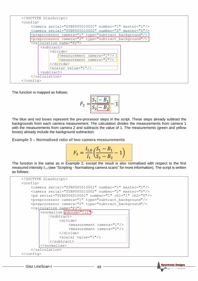
49 Glaz LineScan-I
<!DOCTYPE GlazScript>
<config>
<camera serial="SYBP005010001" number="1" master="1"/>
<camera serial="SYBP005010002" number="2" master="0"/>
<preprocessor camera="1" type="subtract_background"/>
<preprocessor camera="2" type="subtract_background"/>
<calculation name="F2">
<subtract>
<divide>
<measurement camera="1"/>
<measurement camera="2"/>
</divide>
<scalar value="1"/>
<subtract>
</calculation>
</config>
The function is mapped as follows:
𝐹2 =𝑆1 − 𝐵1
𝑆2 − 𝐵2− 1
The blue and red boxes represent the pre-processor steps in the script. These steps already subtract the backgrounds from each camera measurement. The calculation divides the measurements from camera 1 with the measurements from camera 2 and subtracts the value of 1. The measurements (green and yellow boxes) already include the background subtraction.
Example 3 – Normalised ratio of two camera measurements
𝐹3 =𝐼1,0
𝐼1(
𝑆1 − 𝐵1
𝑆2 − 𝐵2− 1)
The function is the same as in Example 2, except the result is also normalised with respect to the first measured intensity I1,0 (see “Scripting - Normalising camera scans” for more information). The script is written as follows:
<!DOCTYPE GlazScript>
<config>
<camera serial="SYBP005010001" number="1" master="1"/>
<camera serial="SYBP005010002" number="2" master="0"/>
<pd serial="SYBP006010001" number="1" ch1="1" ch2="0"/>
<preprocessor camera="1" type="subtract_background"/>
<preprocessor camera="2" type="subtract_background"/>
<calculation name="F3">
<normalise pdnorm="1:1">
<subtract>
<divide>
<measurement camera="1"/>
<measurement camera="2"/>
</divide>
<scalar value="1"/>
</subtract>
</normalise>
</calculation>
</config>
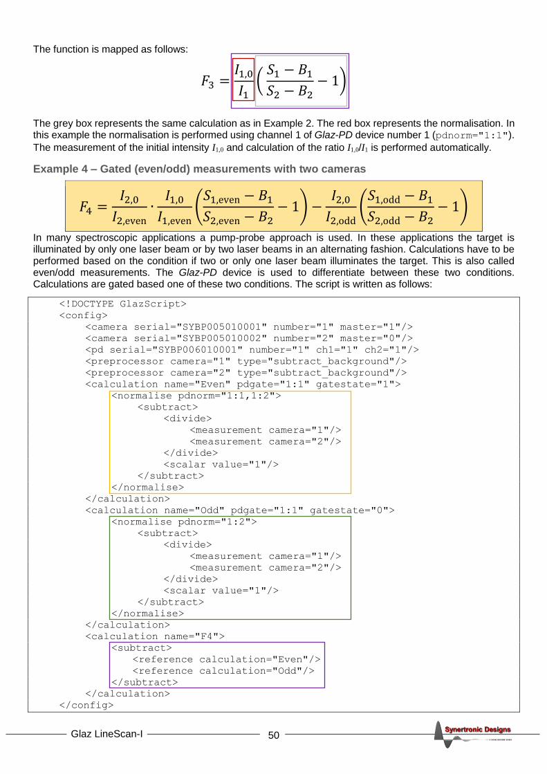
50 Glaz LineScan-I
The function is mapped as follows:
𝐹3 =𝐼1,0
𝐼1(
𝑆1 − 𝐵1
𝑆2 − 𝐵2− 1)
The grey box represents the same calculation as in Example 2. The red box represents the normalisation. In this example the normalisation is performed using channel 1 of Glaz-PD device number 1 (pdnorm="1:1").
The measurement of the initial intensity I1,0 and calculation of the ratio I1,0/I1 is performed automatically.
Example 4 – Gated (even/odd) measurements with two cameras
𝐹4 =𝐼2,0
𝐼2,even∙
𝐼1,0
𝐼1,even(
𝑆1,even − 𝐵1
𝑆2,even − 𝐵2− 1) −
𝐼2,0
𝐼2,odd(
𝑆1,odd − 𝐵1
𝑆2,odd − 𝐵2− 1)
In many spectroscopic applications a pump-probe approach is used. In these applications the target is illuminated by only one laser beam or by two laser beams in an alternating fashion. Calculations have to be performed based on the condition if two or only one laser beam illuminates the target. This is also called even/odd measurements. The Glaz-PD device is used to differentiate between these two conditions. Calculations are gated based one of these two conditions. The script is written as follows:
<!DOCTYPE GlazScript>
<config>
<camera serial="SYBP005010001" number="1" master="1"/>
<camera serial="SYBP005010002" number="2" master="0"/>
<pd serial="SYBP006010001" number="1" ch1="1" ch2="1"/>
<preprocessor camera="1" type="subtract_background"/>
<preprocessor camera="2" type="subtract_background"/>
<calculation name="Even" pdgate="1:1" gatestate="1">
<normalise pdnorm="1:1,1:2">
<subtract>
<divide>
<measurement camera="1"/>
<measurement camera="2"/>
</divide>
<scalar value="1"/>
</subtract>
</normalise>
</calculation>
<calculation name="Odd" pdgate="1:1" gatestate="0">
<normalise pdnorm="1:2">
<subtract>
<divide>
<measurement camera="1"/>
<measurement camera="2"/>
</divide>
<scalar value="1"/>
</subtract>
</normalise>
</calculation>
<calculation name="F4">
<subtract>
<reference calculation="Even"/>
<reference calculation="Odd"/>
</subtract>
</calculation>
</config>

51 Glaz LineScan-I
The function is mapped as follows:
𝐹4 =𝐼2,0
𝐼2,even∙
𝐼1,0
𝐼1,even(
𝑆1,even − 𝐵1
𝑆2,even − 𝐵2− 1) −
𝐼2,0
𝐼2,odd(
𝑆1,odd − 𝐵1
𝑆2,odd − 𝐵2− 1)
Even term Odd term
The yellow and green boxes each represent the same calculation as in Example 3. Except, the even term (yellow box) uses two normalisation factors. In this example channel 1 of the Glaz-PD device number 1 is used to perform the gating function. When a scan is triggered and Glaz-PD channel 1 is also triggered, then the even term will be calculated. When a scan is triggered and Glaz-PD channel 1 is not triggered, then the odd term will be calculated (see “Scripting - Gating calculations” for more information). Since gating can only be applied to calculations, the complete function F4 cannot be represented by a single calculation in the script file. A third calculation needs to be defined. This calculation subtracts the odd term from the even term. This is a reference calculation and it references the “Even” calculation (yellow boxes) and “Odd” calculation (green boxes). The reference calculation is performed each time an “Odd” and “Even” calculation result is available. This happens only with every second scan.
The result for 10 scans could look as follows:
Scan Glaz-PD channel 1 triggered?
“Odd” “Even” “F4”
Calculated? Kept scan result
Calculated? Kept scan result
Calculated? Kept scan result
1 ✓ ✓ All zeros All zeros
2 ✓ All zeros ✓ ✓ ✓ ✓
3 ✓ ✓ All zeros All zeros
4 ✓ All zeros ✓ ✓ ✓ ✓
5 ✓ ✓ All zeros All zeros
6 ✓ All zeros ✓ ✓ ✓ ✓
7 ✓ ✓ All zeros All zeros
8 ✓ All zeros ✓ ✓ ✓ ✓
9 ✓ ✓ All zeros All zeros
10 ✓ All zeros ✓ ✓ ✓ ✓
Average 2,4,6,8,10 1,3,5,7,9 1,3,5,7,9
The ✓ and indicate whether a calculation is performed or not. In addition, the result for kept scans (when keepscans="1") is also indicated. In the bottom row the scan numbers used to calculate the averages is
shown.

52 Glaz LineScan-I
IMPORTANT NOTICE
Synertronic Designs reserves the right to make corrections, modifications, enhancements, improvements, and other changes to its products and services at any time and to discontinue any product or service without notice. Customers should obtain the latest relevant information before placing orders and should verify that such information is current and complete. All products are sold subject to Synertronic Designs’ terms and conditions of sale supplied at the time of order acknowledgment.
Synertronic Designs assumes no liability for applications assistance or customer product design. Customers are responsible for their applications using Synertronic Designs products. To minimize the risks associated with customer applications, customers should provide adequate operating safeguards.
Reproduction of information in Synertronic Designs data sheets, summary notes and brochures is permissible only if reproduction is without alteration and is accompanied by all associated warranties, conditions, limitations, and notices. Reproduction of this information with alteration is an unfair and deceptive business practice. Synertronic Designs is not responsible or liable for such altered documentation.
Synertronic Designs on the web: www.synertronic.co.za
E-mail: [email protected]
Postal address: Kaneel Cr 34 Stellenbosch 7600 South Africa