HIGH SPEED ER PROBES - ASELCO
7
MICROCOR ® HIGH SPEED ER PROBES - Microcor ® Probes are an integral component of the new high‐ resolution Microcor ® system, including the Microcor Wireless Transmitter. Special design of the probes provides advanced thermal performance, and reliable operation in all environments including sour service. Two forms of probe element are available – flush and cylindrical. Several mounting configurations are available, the most common of which allow the probes to be inserted and removed under full process operating conditions without shutdown. M4000 Series Probes The M4000 series probes are called retrievable probes and are designed for use in the COSASCO ® high pressure access fitting range. This permits probes to be removed or replaced at process conditions up to 6000 psi (400 bar), and temperatures up to 400°F (204°C) with the COSASCO ® Retriever and service valve. Note: All 4000 series probes must be installed with an overshot adaptor (P/N 126292) to maintain connector cleanliness (see note on back page for details). M3000 Series Probes The M3000 series probes are called retractable probes that can be removed or replaced under full system operating conditions, up to 1500 psi (100 bar) and 425°F (218°C). With high temperature versions this may be extended to 1000°F (520°C) at pressures up to 1000 psi (67 bar). This series uses a sliding stuffing box seal. M2000 Series Probes The M2000 series probes are fixed probes that are used in high pressure, or especially hazardous process streams. However, they cannot be removed or replaced without system shutdown, unless installed in a bypass loop. The Microcor ® MT‐9485A transmitter and Microcor Wireless Transmitter have to be closely coupled to the probe. This is achieved with a short connecting adapter, so that the transmitter is essentially mounted on the end of the probe. This is the recommended configuration. If conditions prevent this then a short cable of no more than 6 ft (2 meters) is available. The Microcor ® technology measures the metal loss that is occurring on the probe element with very high resolution. Consequently, it is useable in virtually any environment, as distinct from electrochemical methods which may only be used in essentially aqueous environments. From the collection of these metal loss readings over time, the corrosion rate can be computed. The very high resolution of the metal loss measurements enable the corrosion rate to be determined in minutes or hours, and provide rapid feedback on changes of corrosion rates, 50 to 100 times faster than other metal loss methods. The high resolution and sensitivity means that you can now obtain rapid response and a long probe life with the standard F10 and T10 probe elements. However, if necessary, other probe element thicknesses are available. The thinner the element, the faster is the response. The thicker the element, the longer is the probe life. Flush Probes are used for best thermal performance where flush mounting with the pipe wall is desirable or essential. A typical example is the bottom‐of‐line locations in oil and gas production pipelines. In these applications, water films commonly collect in the bottom of the line and are the primary cause of corrosion. The flush probe ensures the whole of the probe element is exposed to the water film, whereas a cylindrical probe would only be partially exposed. In other pipeline applications flush probes are essential if the line is pigged, thereby avoiding possibility of probe damage. Cylindrical Probes are suited to more aggressive environments. Since there is no sealing material other than the parent metal, they are suitable for virtually any aggressive environment. The measurement area of the element is much greater in this design and is suitable for use in a single phase flow. In multiphase or stratified flows care must be taken to position the whole probe element in the corrosive phase to be monitored M4700 Flush and M4500 Cylindrical Probes M4700 Probe in Cosasco Fitting
Transcript of HIGH SPEED ER PROBES - ASELCO

MICROCOR®
HIGH SPEED ER PROBES
-
Microcor® Probes are an integral component of the new high‐resolution Microcor® system, including the Microcor Wireless Transmitter. Special design of the probes provides advanced thermal performance, and reliable operation in all environments including sour service. Two forms of probe element are available – flush and cylindrical. Several mounting configurations are available, the most common of which allow the probes to be inserted and removed under full process operating conditions without shutdown. M4000 Series Probes The M4000 series probes are called retrievable probes and are designed for use in the COSASCO® high pressure access fitting range. This permits probes to be removed or replaced at process conditions up to 6000 psi (400 bar), and temperatures up to 400°F (204°C) with the COSASCO® Retriever and service valve. Note: All 4000 series probes must be installed with an overshot adaptor (P/N 126292) to maintain connector cleanliness (see note on back page for details). M3000 Series Probes The M3000 series probes are called retractable probes that can be removed or replaced under full system operating conditions, up to 1500 psi (100 bar) and 425°F (218°C). With high temperature versions this may be extended to 1000°F (520°C) at pressures up to 1000 psi (67 bar). This series uses a sliding stuffing box seal. M2000 Series Probes The M2000 series probes are fixed probes that are used in high pressure, or especially hazardous process streams. However, they cannot be removed or replaced without system shutdown, unless installed in a bypass loop. The Microcor® MT‐9485A transmitter and Microcor Wireless Transmitter have to be closely coupled to the probe. This is achieved with a short connecting adapter, so that the transmitter is essentially mounted on the end of the probe. This is the recommended configuration. If conditions prevent this then a short cable of no more than 6 ft (2 meters) is available.
The Microcor® technology measures the metal loss that is occurring on the probe element with very high resolution. Consequently, it is useable in virtually any environment, as distinct from electrochemical methods which may only be used in essentially aqueous environments. From the collection of these metal loss readings over time, the corrosion rate can be computed. The very high resolution of the metal loss measurements enable the corrosion rate to be determined in minutes or hours, and provide rapid feedback on changes of corrosion rates, 50 to 100 times faster than other metal loss methods. The high resolution and sensitivity means that you can now obtain rapid response and a long probe life with the standard F10 and T10 probe elements. However, if necessary, other probe element thicknesses are available. The thinner the element, the faster is the response. The thicker the element, the longer is the probe life. Flush Probes are used for best thermal performance where flush mounting with the pipe wall is desirable or essential. A typical example is the bottom‐of‐line locations in oil and gas production pipelines. In these applications, water films commonly collect in the bottom of the line and are the primary cause of corrosion. The flush probe ensures the whole of the probe element is exposed to the water film, whereas a cylindrical probe would only be partially exposed. In other pipeline applications flush probes are essential if the line is pigged, thereby avoiding possibility of probe damage. Cylindrical Probes are suited to more aggressive environments. Since there is no sealing material other than the parent metal, they are suitable for virtually any aggressive environment. The measurement area of the element is much greater in this design and is suitable for use in a single phase flow. In multiphase or stratified flows care must be taken to position the whole probe element in the corrosive phase to be monitored
M4700 Flush and M4500 Cylindrical Probes
M4700 Probe in Cosasco Fitting

MICROCOR® HIGH SPEED ER PROBES
M4000 Series Retrievable Probes ‐ Mounts in Cosasco® High Pressure Access Fitting, maximum operation
§ Most popular configurations 6000 psi (413 bar) and 500°F (260°C), maximum retrieval 400°F (204°C) M3000 Series Retractable Probes – Mounts in Model 60 Access Valve 1” or 1.5” Assembly, Standard Probe Lengths 18”, 24”, 30”,
& 36”. Safety Clamp Assembly required for pressures over 100 psi and/or temperatures over 150°F
§ M4500
0.25” Length Increments Optional Shields available
Note: For high velocity process conditions it is recommended that Wake Frequency Calculations be performed – please contact Cosasco representative for further details.
§M4700
0.125” Length Increments Note: For flush devices which are protruding into the line that may experience high velocity process conditions it is recommended that Wake Frequency Calculations be performed – please contact Cosasco representative for further details.
§ M3500/3500HT
Optional Shields and Safety Clamps Requires 1” full port ball valve HT = High Temperature Note: For high velocity process conditions it is recommended that Drag Force Calculations be performed – please contact
Cosasco representative for further details.
M3501/3501HT
Replacement insert for M3500 HT = High Temperature Note: For high velocity process conditions it is recommended that Drag Force Calculations be performed – please contact
Cosasco representative for further details.
§ M3700
1.25” Diameter Head Optional Safety Clamps Requires 1.5” ball or gate valve & 1” to 1.5” swaged nipple connection between valve & stuffing box. Note: For flush devices which are protruding into the line that may experience high velocity process conditions it is recommended that Drag Force Calculations be performed –
please contact Cosasco representative for further details.
M3701
Model 3700 replacement insert Note: For flush devices which are protruding into the line that may experience high velocity process conditions it is recommended that Drag Force Calculations be performed –
please contact Cosasco representative for further details.
MICROCOR® HIGH SPEED ER PROBES
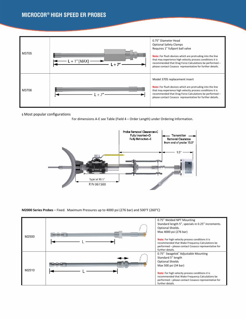
§ Most popular configurations For dimensions A‐E see Table (Field 4 – Order Length) under Ordering Information.
M2000 Series Probes – Fixed. Maximum Pressures up to 4000 psi (276 bar) and 500°F (260°C)
M2500
0.75” Welded NPT Mounting Standard length 5”, specials in 0.25” increments. Optional Shields. Max 4000 psi (276 bar) Note: For high velocity process conditions it is recommended that Wake Frequency Calculations be performed – please contact Cosasco representative for further details.
M2510
0.75” Swagelok® Adjustable Mounting Standard 5” length Optional Shields Max 500 psi (34 bar) Note: For high velocity process conditions it is recommended that Wake Frequency Calculations be performed – please contact Cosasco representative for further details.
M3705
0.75” Diameter Head Optional Safety Clamps Requires 1” fullport ball valve Note: For flush devices which are protruding into the line that may experience high velocity process conditions it is recommended that Drag Force Calculations be performed – please contact Cosasco representative for further details.
M3706
Model 3705 replacement insert Note: For flush devices which are protruding into the line that may experience high velocity process conditions it is recommended that Drag Force Calculations be performed – please contact Cosasco representative for further details.
MICROCOR® HIGH SPEED ER PROBES
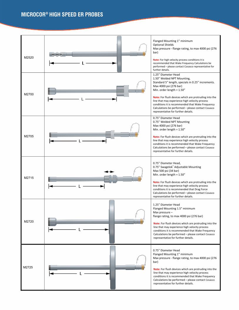
M2520
Flanged Mounting 1” minimum Optional Shields Max pressure ‐ flange rating, to max 4000 psi (276 bar) Note: For high velocity process conditions it is recommended that Wake Frequency Calculations be performed – please contact Cosasco representative for further details.
M2700
1.25” Diameter Head 1.50” Welded NPT Mounting, Standard 5” length, specials in 0.25” increments. Max 4000 psi (276 bar) Min. order length = 1.50” Note: For flush devices which are protruding into the line that may experience high velocity process conditions it is recommended that Wake Frequency Calculations be performed – please contact Cosasco representative for further details.
M2705
0.75” Diameter Head 0.75” Welded NPT Mounting Max 4000 psi (276 bar) Min. order length = 1.50” Note: For flush devices which are protruding into the line that may experience high velocity process conditions it is recommended that Wake Frequency Calculations be performed – please contact Cosasco representative for further details.
M2715
0.75” Diameter Head, 0.75” Swagelok® Adjustable Mounting Max 500 psi (34 bar) Min. order length = 1.50” Note: For flush devices which are protruding into the line that may experience high velocity process conditions it is recommended that Drag Force Calculations be performed – please contact Cosasco representative for further details.
M2720
1.25” Diameter Head Flanged Mounting 1.5” minimum Max pressure – flange rating, to max 4000 psi (276 bar) Note: For flush devices which are protruding into the line that may experience high velocity process conditions it is recommended that Wake Frequency Calculations be performed – please contact Cosasco representative for further details.
M2725
0.75” Diameter Head Flanged Mounting 1” minimum Max pressure ‐ flange rating, to max 4000 psi (276 bar) Note: For flush devices which are protruding into the line that may experience high velocity process conditions it is recommended that Wake Frequency Calculations be performed – please contact Cosasco representative for further details.

MICROCOR® HIGH SPEED ER PROBES
Ordering Information
NOTE: T50 Probes are no longer available.
Response time to corrosion upset conditions depends on the probe element thickness, the magnitude of the upset corrosion rate and the typical system noise. The adjacent graph shows the typical time required to detect the new corrosion rate trend over the background noise experienced in the real world environment. This is based on 50 Probe Life Units (PLU’s) change of the 262,144 PLU’s that correspond to the full probe span. 1 PLU is the resolution of the Microcor® High Speed ER transmitter. For example (see white lines), if there is a sudden change from 0 to 10 mpy in the corrosion rate, this will be detectable in approximately 0.85 hours, or 50 minutes. Probe Life (years) = Probe Span (mils) Average Corrosion Rate (mpy)
F10 and T10 probes are the most popular, as they provide a good combination of sensitivity and probe life.
Probe Model Number Configuration
Field 1 Field 2 Field 3 Field 4 Field 5 Field 6 Field 7
Probe Model Model # Element Type
Element Alloy
Order Length L
M3500/3500HT
All Probes
18”, 24”, 30”, 36” Nominal
Safety Clamp Element Shield
Stuffing Box
M3501/3501HT
M3700 Safety Clamp
M3701
M3705 Safety Clamp
M3706
M4500 1/4” Increments Element Shield
M4700 1/8” Increments
M2000 Series Specify Process Side, Probe Length, Mounting Type, Shield Requirements
Field 2 ‐ Element Type – see chart below
Cylindrical Element Probes ‐ (Models Mx500)
T10 10 mils thickness (5 mils probe span)
T20 20 mils thickness (10 mils probe span)
Flush Element Probes ‐ (Models Mx700, Mx701, Mx705, Mx706)
F10 10 mils thickness (5 mils probe span)
F20 20 mils thickness (10 mils probe span)
Field 3 – Probe Element Alloy (UNS Number)
K03005 Carbon Steel
S30403 304/304L Stainless Steel
S31603 316/316L Stainless Steel
NOTE: Many other alloy options are available. Contact RCS for price and availability.

MICROCOR® HIGH SPEED ER PROBES
Model M3000 Series probes have probe locking ferrules on the top of the stuffing box that have been tested up to 3000 psi, twice the maximum rating of the probes. The design of the probes also provides a shoulder or a shield on the probe body that prevents the probe from passing through the stuffing box. However, for added safety above 150 psig or 150F process conditions, the additional safety clamp should be used. The safety clamp threaded rods provide a secondary lock to hold the probe in the inserted position. The included safety wire provides a guide to full retraction of the probe through the valve at the time of probe removal. The stuffing box seal loading nut is provided with drilled holes and wire to allow locking of the
nut to prevent loosening under heavy vibration conditions.
Microcor® probes may be subject to high flow velocities in some processes. This is not a problem for the flush element (x700 series) probes, since the element is recessed in its mounting so that the front face of the element is flush with the pipe or vessel wall, and not subjected to any significant bending forces due to the flow or vibration due to flow vortex shedding patterns. However, cylindrical element (Mx500 series) probes are subject to these forces and must be protected at higher velocities as indicated in the table below. If the velocity is low enough, it is preferred to run the probe without a shield as it gives full exposure of the element to the process flow. When a standard shield is used, it includes a probe tip support that provides protection from fatigue of the probe element at its base caused by flow vortex shedding. It also provides protection from the additional bending forces from the flow. For high velocity shield has holes only on the sides of the shield. The blank side should be positioned to face into the flow and protect the element from direct impingement or erosion, while
the side holes still permit circulation around the probe element.
Field 4 ‐ Order Length = L
L Model Probe Length
L M4500 2.75” (T10) or 4.5” (T20) to 18” in 0.25” Increments. Consult RCS over 15” and 25 ft/s liquid velocity
L = P + T + 1.25” rounded down, where, P = Penetration inside pipe or vessel T = Wall Thickness of pipe or vessel Formula is based on standard access fitting of 5.25” and 1/16” weld gap per ANSI B31.1
L M4700 1.25” to 18” in 0.125” Increments. Consult RCS over 15” and 25 ft/s liquid velocity
L = 18 24 30 36
M3000 Series
M3500 Series M3700/3705
DIM T10 T20 DIM
A L – 1.35” L+ 6.4” A L + 1”
B L + 6.5” L + 8.25” B L + 7”
C L + 7.5” L + 9.25” C L + 5”
D L – 10” D L – 12.63”
E L + 5” E L + 8”
L M2000 Series Probe tip to process side of mounting
Field 5 ‐ Safety Clamp
Model M3000 Series Only
0 None
1 Safety Clamp over 100 psi and/or 150F

MICROCOR® HIGH SPEED ER PROBES
Field 5 or 6 ‐ Shields
Model Mx500 Only
0 No Shield ‐ Liquids up to 8ft/s, Gases 25ft/s
1 Standard Shield – liquids up to 25ft/s, Gases 75ft/s
2 High Velocity Shield – Liquids up to 50ft/s, Gases 150ft/s
Field 7 ‐ Stuffing Box Material * Model M3000 Series Only
0
M3500 Carbon Steel for cs, 316 ss, for alloys up to ss. For higher alloys use option 1 Hastelloy C‐276
M3500HT 316 ss for alloys up to ss. For higher alloys use option 1, Hastelloy C‐276
1 Hastelloy C‐276 Stuffing Box
How to Order: Order Model # Field 1 – Field 2 – Field 3 – Field 4 – Field 5 – Field 6 – Field 7 Example: M3500 – T10 – K03005 – 18 – 1 – 1 ‐ 0 Model # M3500 with T10‐K03005 element, 18” length, with safety clamp, standard element shield, stuffing box carbon steel Note: Model 4000 Series Probe Connection during Installation Microcor probe connectors must be kept clean for proper operation. To ensure this on Model 4000 series probe an Overshot Adaptor should be fitted to the hollow plug during probe installation and retrieval. This seals the area of the probe connector from the process fluid during installation and retrieval.
Bulletin #150‐Q Rev. Date: 11/16/2015
NOTE: These shield recommendations are based on the exposure of the probe element. For liquid flows over 50 ft/s or gas flows over 75 ft/s, where the probe protrudes into the pipe or vessel more than 12” on model M3000 series probes, or 15” on other models contact RCS with details to check suitability for service.
*Probe body alloy matches probe element alloy, except for carbon steel in M3500HT where probe body is stainless steel.
Overshot Adapter
Hollow Plug
Overshot Adapter: P/N 126292
Cosasco 11841 Smith Avenue Santa Fe Springs, CA 90670, USA Tel: 1‐562‐949‐0123 Email: [email protected] Web Site: www.cosasco.com
©Rohrback Cosasco Systems, Inc. All rights reserved The contents of this publication are presented for information purposes only, and while effort has been made to ensure their accuracy, they are not to be construed as warranties or guarantees, express or implied, regarding the products or services described wherein or their use or applicability. We reserve the right to modify or improve the designs or specifications of our products at any time without notice. Rohrback Cosasco Systems Corrosion Monitoring Equipment is manufactured and sold under one or more of the following US Patents: 4138878, 4238298, 4338563, 4514681, 4537071, 4587479, 4605626, 4625557, 4755744, 4839580, 4841787, 4882537 5243297