High Speed Direct Drive Motors Enabled by SiC Power Devices
12
Paulo Guedes-Pinto High Speed Direct Drive Motors Enabled by SiC Power Devices High-Megawatt (HMW) Direct-Drive Motor Workshop September 4 th , 2014
Transcript of High Speed Direct Drive Motors Enabled by SiC Power Devices

Paulo Guedes-Pinto
High Speed Direct Drive Motors
Enabled by SiC Power Devices
High-Megawatt (HMW) Direct-Drive Motor
Workshop
September 4th, 2014

High Speed v. Conventional Motor Comparison
2 MW 1,800 rpm v. 2 MW 22,500 rpm
1100
85
0
40
0 50
0
1850
14
75
910
1130
Volume: 3.1 m3
4,848 kg
Volume: 0.85 m3
1,787 kg

High Speed Motor Technology
Design Considerations • Rotor dynamic performance
– Mode separation and margin across entire speed range
– Supercritical rotor complicates bearing design and reliability
• Thermal management – High power density requires liquid cooling in the stator
– Eddy current losses require use of Litz wire or Roebel coils in the stator winding
– Core losses require use of thin laminations (0.18 mm or less)
– Unconventional air circulation schemes to overcome pressure drop at air gap
– Oil film bearings are lossy. Magnetic bearings are preferred
– Power quality (or lack thereof) affects rotor heating
– High efficiency is critical
• Stress management – Rotor containment
– Magnetic bearing rotating components

High Speed Motor Technology
Design Considerations • Torque pulsation
– Large air gaps and good power quality reduce torque pulsation
• Motor insulation and coil design – Litz wire or Roebel coils to limit eddy current losses
– Corona and grading tape use in medium voltage to reduce insulation stress and overheating
– Lead design must consider skin effect
– Thermal conductivity v. dielectric stress
– End turn length
• Power quality – Drive and motor ideally designed in conjunction
– Limitations on switching frequency in drives can produce low and high order harmonics
– Magnet configuration in PM machines can affect power quality

Variable Frequency Drives for High Speed Application
• High frequency drives are usually de-rated versions of commercial low frequency drives – Low switching frequency is not conducive to good power quality
• Compliance to IEEE 519 does not guarantee good motor performance – Current THD 2% or better to reduce rotor heating and prevent
catastrophic rotor failure
• Interleaving can support high fundamental frequency without increasing switching frequency
• Low voltage cell design offers opportunities to improve power quality and efficiency – Drive segmentation – Use of SiC MOSFET
– High switching frequency (>10 kHz)
CONTROL
“MAINS”
SLICE
TWMC’s VersaBridge
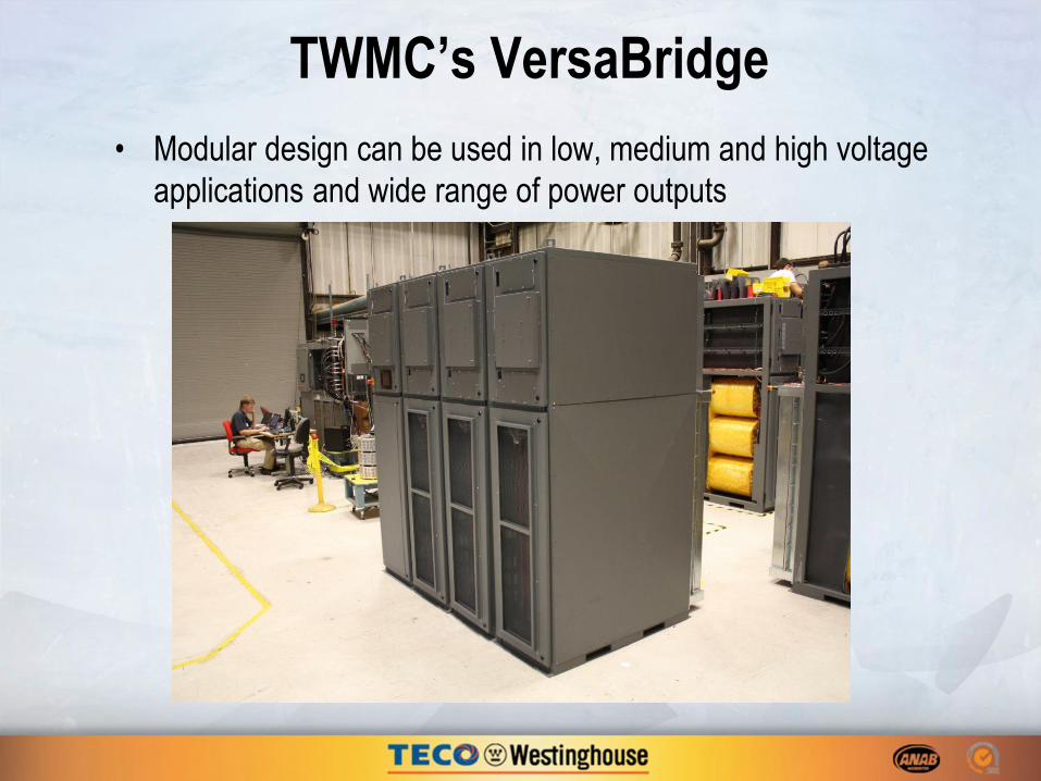
• Modular design can be used in low, medium and high voltage
applications and wide range of power outputs

TWMC’s VersaBridge
• Modular design can be used in low, medium and high voltage
applications and wide range of power outputs
2,250 kW 4,000 kW

VersaBridge System Schematics

36-Pulse Rectifier with two 18-pulse Transformers
-6000
-4000
-2000
0
2000
4000
600036-Pulse Input Voltage (V)
0.2 0.25
-100
-50
0
50
100
Time (s)
36-Pulse Input Current (A)
θ = -20°
θ = 0°
Z
θ = 20°
ZV, I
θ = -20°
θ = 0°
Z
θ = 20°
Z
Z
Z
θ = -5°
θ = 5°

TWMC VersaBridge
Multi-Level Topology
• Unidirectional Power
– 750 kW/Slice
– Carrier Frequency
• (2n+1) x Device SF – n = number of series cubes
– Device SF = 0.3 to 6 kHz
• 4.2 kHz to 6 kHz typical
• 20 kHz or higher possible
– Input
• 18 pulse transformers
• 18 + 18 pulse system
– Induction Motor Control
• V/Hz
• Vector
– Independent Liquid Cooled
• Electronics
• Transformer
• Bidirectional Power
– 500 kW/Slice
– Carrier Frequency
• (2n+1) x Device SF – n = number of series cubes
– Device SF = 0.3 to 6 kHz
• 4.2 kHz to 6 kHz typical
• 20 kHz or higher possible
• 6 kHz input
– Input
• 6 kHz typical carrier
• Electronic phase shift
• More slices →lower grid THD
– Induction Motor Control
• V/Hz output only
• Vector input & output
– Independent Liquid Cooled
• Electronics
• Transformer

TWMC VersaBridge
Multi-Level Topology
• Existing – Semiconductor Solution:
• IGBTs + Diodes (Si based)
– Transformer Solution:
• Iron core transformer
– Slice
• Power converter + Transformer
– Liquid Cooling
– Distributed Control
– Series & Parallel Solutions
• Future Vision – Semiconductor Solution:
• IGBT + SiC Diode
• SiC Transistor +Diode
– Transformer Solution
• None – motor winding and VSD matched
• High frequency core
– Slice
• Power converter (+ Transformer)
– Advanced Liquid Cooling
– Enhanced Distributed Control
– Series & Parallel Solutions

TWMC VersaBridge
Transformerless Topology
No Transformer High Frequency
Isolation Transformer
M
9-Phase
Motor
3-Phase
High-frequency
Transformer
3-Phase
M
3-Phase
Motor