High Side Intelligent Power Switches for Automotive and...
41
TM September 2013
Transcript of High Side Intelligent Power Switches for Automotive and...

TM
September 2013

TM 2
• Freescale’s intelligent high side switches are designed to
control a wide variety of loads in automotive and industrial
systems. This presentation describes Freescale’s high
side switch portfolio and roadmap, device features,
considerations for their use, potential applications and
available design and support tools.

TM 3
1. Low Voltage Loads and their System Requirements
2. Freescale’s Technology Solutions
3. Freescale’s Product Solutions for 12V and 24V Systems
4. Device Features
5. Ecosystem and Design Support

4 TM
Fuel Pump (MC33981)
Fuse Box
Body / lighting
Application Loads
Lighting Halogen & incandescent lamps, LEDs,
Xenon HID, …
DC motor Fuel pump, wiper, fan, …
Solenoid Xenon shutter, relay coil, …
Resistor 0² heater, seat heater, …
Power
Distribution
Other modules or subcircuits

5 TM
• Electric doors
• Wiper
• Washer pump
• Machine inspection
• Vending machines
• HVAC
• Hospital bed controller
DC Motors
• Solenoids
• Water and fluid control app
• Valve controllers for thermostats
• Home Automation system
• Xenon
• Halogen
• Incandescent
• LEDs
• PLC
• Low end robotic
• Industrial printing systems
• POS terminals
Inductive loads Lighting loads
Factory Automation
Start Stop

6 TM
• Any load with currents < 1A
• Any load that requires PWMing
− Bulb protection (against high voltage)
− Dimming
− Daytime running lamps
− Soft-start
− Motor speed control or back EMF detection
• Loads requiring sophisticated diagnostics
• Systems requiring careful over current management to protect wiring
• High side switched loads <20A
• 24V systems
• Loads that require blocking reverse battery current
• Low or high side switched loads with currents > 20A
• H-bridge or ½ H-bridge topologies > 10A
Mo
re lik
ely
to
use
so
lid s
tate
de
vic
es
Le
ss lik
ely

7 TM
Vbatt
freewheel
diode
Vgate = 10V
“Low Side”
switch
Solenoid
or other
load
Vbatt
freewheel
diode
Vgate = Vbatt+10V
“High Side”
switch
Solenoid
or other
load
G
G
D
D
S
S

8 TM
• Module cost
• Module size and weight
• Module mounting location and orientation
• Load variations with vehicle features
• Robustness
• Module manufacturability
• Quality
• Power density and thermal management
• Load/fuse assignment
• Harness protection
• Inrush currents much greater than operating current
• Short circuit management (retry strategy), especially at cold temperature
• FMEA (failure mode) considerations for headlamps and brake lamps
• Detecting an incorrect bulb size or a failure in paralleled lamps
• Diagnostics
• Module sleep state current
• Conducted and radiated emissions for PWMed loads; susceptibility

9 TM
• Operating profile for trucks might be 300,000km/y
• Wire harness for 24V system is often much longer than in passenger vehicles
• Potentially up to 20 meters from module to load (up to 40m with a trailer)
• Potentially up to 20 meters from battery to module (for a distributed architecture)
• Increases wiring inductance and the possibility of wiring harness faults
• 24V systems have more loads than 12V systems and more of those loads are motors and solenoids
• motors are often PWMed @ ~1kHz from 5% to 100% whereas lighting is PWM-ed at 100 to 200Hz
• Vehicular transient specifications are more severe in 24V systems

10 TM
• Control and protection circuitry includes:
− Overload protection
− Multi-step overcurrent detection
− Short-circuit protection
− Over-temperature protection
− High-voltage survivability
− Under-voltage and over-voltage shutdown with hysteresis
12 mm by 12 mm
PQFN
32-pin
SOICep
• A SmartPower device is a Power IC with some digital content. It interfaces between an MCU and a load.
• “eXtreme Switch” is Freescale’s brand name for high current “SmartPower”.
• The eXtremeSwitch limit of the load current is 2A-30A DC and 150A transient. Loads are mostly bulbs, but also DC motors, solenoids or submodules
• eXtremeSwitch devices are available for:
• 12V systems (45V technology): Lighting, “Main switch”, DC motor control
• 24V systems (65V technology): General purpose switch for trucks, buses and special engines
• A dual chip solution in a package is the most optimized (cost) for such current (so far).
• Technologies used are SmartMOS (SM8MV) + Vertical Power MOSFET (HD5→Lfet) + Package (PQFN → SOICep)

11 TM
Overload
Module output
short-circuit
(20m)
Load
short-circuit
(100m)
loads
+ -
VPWR
Over
voltage
Over
temp
Under
voltage
Ground
loss
Load Shorted to
Battery
Open load
OFF – ON – LED Current sense
high precision Automatic PWM
System Diagnostic
Open load ON – OFF – LED
Load Shorted to Battery
Current sense
Switch Protection
Over temp
Ground loss
Reverse Battery
System Protection
Over-under voltage
Module output short-circuit
Load short-circuit
Overload
eXtreme
Switch
SPI Fault Mgmt.
Simplified Software

12 TM
Part Number# of Outputs and
On-Resistance
Total
Outputs #Package
Low
Operating Voltage
High
Operating Voltage
Pin to Pin
Compatibility
Software
CompatibilityStatus / Launch
MC07XS3200EK Dual 7mΩ 2 32-pin SOICeP 6V 20V - In production
MC10XS3425EK Dual 10mΩ, Dual 25mΩ 4 32-pin SOICeP 6V 20V - In Production
MC10XS3412DHFK Dual 10mΩ, Dual 12mΩ 4 24-pin PQFN 6V 20V In Production
MC10XS3435DHFK Dual 10mΩ, Dual 35mΩ 4 24-pin PQFN 6V 20V In Production
MC15XS3400DHFK Quad 15mΩ 4 24-pin PQFN 6V 20V In Production
MC35XS3400DHFK Quad 35mΩ 4 24-pin PQFN 6V 20V In Production
MC09XS3400AFK Quad 9mΩ 4 24-pin PQFN 6V 20V In Production
MC10XS3535HFK Triple 10mΩ, Dual 35mΩ 5 24-pin PQFN 7V 20V In Production
MC35XS3500HFK Penta 35mΩ 5 24-pin PQFN 7V 20V In Production
MC06XS3517AFK Triple 6mΩ, Dual 17mΩ 5 24-pin PQFN 7V 20V In Production
MC07XS6517EK Triple 7mΩ, Dual 17mΩ 5 54-pin SOICeP 7V 18V Launch Q3 2013
MC17XS6500EK Penta 17mΩ 5 32-pin SOICeP 7V 18V Launch Q3 2013
Part Number# of Outputs and
On-Resistance
Total
Outputs #Package
Low
Operating Voltage
High
Operating Voltage
Pin to Pin
Compatibility
Software
CompatibilityStatus / Launch
MC06XS4200FK On-Resistance 2 23-pin PQFN 8V 36V In production
MC10XS4200FK Dual 10mΩ 2 23-pin PQFN 8V 36V In Production
MC20XS4200FK Dual 20mΩ 2 23-pin PQFN 8V 36V In production
Part Number# of Outputs and
On-Resistance
Total
Outputs #Package
Low
Operating Voltage
High
Operating Voltage
Pin to Pin
Compatibility
Software
CompatibilityStatus / Launch
MC33981ABHFK Single 4mΩ, 60KHz 1 16-pin PQFN 6V 27V - - In production
MC33982CHFK Single 2mΩ 1 16-pin PQFN 6V 27V In production
MC33984CHFK Dual 4mΩ 2 16-pin PQFN 6V 27V In production
MC33988CHFK Dual 8mΩ 2 16-pin PQFN 6V 27V In production√ √
√
√
12V Family Devices
24V Family Devices
Main Switch Devices
√
√
√ √
√ √
Extended operating voltage range:
In extended mode, the functionality is guaranteed but not the electrical parameters specified
12V Products: 4.0 to 28V (vs. 6.0 to 20V)
24V Products: 6.0 to 58V (vs. 8.0 to 36V)

13 TM
MC 10 XS 4 2 00 FK / R2
QUALIFICATION STATUS
PC PRE-QUALIFICATION,
ENGINEERING SAMPLES
MC FULLY QUALIFIED
SC CUSTOM DEVICE
ON-RESISTANCE
06 = 6mΩ
10 = 10mΩ
20 = 20mΩ
TAPE AND REEL
R2 TAPE AND REEL
PACKAGE DESIGNATOR
FK Pb FREE
FAMILY
XS = eXtreme SWITCH
FAMILY NUMBER
4 = 24V
NUMBER OF OUTPUTS
2 = 2 OUTPUTS (dual)
4 = 4 OUTPUTS (quad)
5 = 5 OUTPUTS (penta)
RESERVATION
00
SP D 10 _24V
SELF PROTECTED
ON-RESISTANCE
06 = 6mΩ
10 = 10mΩ
20 = 20mΩ NUMBER OF OUTPUTS
S = 1 OUTPUT (single)
D = 2 OUTPUTS (dual)
Q = 4 OUTPUTS (quad)
P = 5 OUTPUTS (penta)
Nickname
Part Number

14 TM
Low End
Low Feature
eXtremeSwitch
eXtremeSwitch 12V are optimized
for centralized modules and external lighting modules
eXtremeSwitch are optimized for High
current loads starting from 15W
Bulb type
example
Bulb (W)
And
Partitioning
eSwitch
Fit
High Beam
Low Beam
Fog lamp
Flasher
Stop
Rear
Repeater
LED rear
100%
20%

15 TM
• eXtremeSwitches are capable of driving from Xenon HID module (High current) to 10W or LED module (Low current).
• eXtremeSwitch Rdson is oversized for loads below 21W unless:
The customer is looking for integration
The customer is willing to have a single module capable of driving either LED (low current) or standard lamp (high current) on the same output Car options management

16 TM
Product
Family Part Number
Open load
ON-OFF-LED
Load
Shorted to
Battery
Temperature
pre-warning
Flag
Analog
meas.
I - T° - V
Overtemp
hysteresis
(w/ Flag)
Overtemp shutdown
+ time based retry
(w/ Flag)
Ground loss -
Reverse batt.
Load
dump
Over / Under
Voltage
ECU output
short circuit
latchoff
Load short
circuit or
overload
latchoffMain MC33981ABHFK / R2 A - - x - x - - x - x x 41 V x x - x
Main MC33982CHFK / R2 A x - - - x - - x - x x 41 V x x - x
Main MC33984CHFK / R2 A x - - - x - - x - x x 41 V x x - x
Main MC33988CHFK / R2 A x - - - x - - x - x x 41 V x x - x
12V MC07XS3200EK x x x x x x - - - x x x 41 V x x x x
12V MC09XS3400AFK / R2 x x x x x x - - - x x x 41 V x x x x
12V MC10XS3412DHFK / R2 x x x x x x - - - x x x 41 V x x x x
12V MC10XS3425EK x x x x x x - - - x x x 41 V x x x x
12V MC10XS3435DHFK / R2 x x x x x x - - - x x x 41 V x x x x
12V MC15XS3400DHFK / R2 x x x x x x - - - x x x 41 V x x x x
12V MC35XS3400DHFK / R2 x x x x x x - - - x x x 41 V x x x x
12V MC06XS3517AFK / R2 x x x x x x x - - x x x 41 V x x x x
12V MC10XS3535HFK / R2 x - x x x x x - - x x x 40 V x x x x
12V MC35XS3500HFK / R2 x - x x x x - - - x x x 40 V x x x x
24V MC06XS4200FK / R2 x x x x x x x - - x x x 58 V x x x x
24V MC10XS4200FK / R2 x x x x x x x - - x x x 58 V x x x x
24V MC20XS4200FK / R2 x x x x x x x - - x x x 58 V x x x x
"X" Feature available
"-" Feature not available
Protection Table Switch protection System ProtectionSystem Diagnostic
A = available with analog
current measurement
Intelligence
• Protections, diagnostics SPI configurable
Safety
• In case of MCU failure, device protects all the system
intelligence & safety
• During system failure, Fail Safe mode can activate loads with full protection

17 TM
SPI interface for programmability, full diagnostics
Full diagnostic, no real time fault mgt needed
High power density
Extremely low sleep state current
Multi-step over current strategy with auto-restart
Robust and reliable solution with failsafe operation
Specific configuration for bulbs, HID, LED
Easy PWM management, EMC optimized
Embedded PWM function with optimized slew rates
Outputs under fully control and protected in case of MCU damage
External or Internal watchdog with failsafe management.
LFET technology introduction significantly reduces on-resistance
Higher over current thresholds to accommodate newest lamps
Option for dual in SOIC with exposed thermal pad (EVL compliant)
Intend for a complete and scalable family in term of software and footprint
It provides diagnostics for light emitting diodes (LEDs) with an enhanced current sense
precision with synchronization pin
It combines flexibility through daisy chainable 5.0MHz SPI, extended digital and analog
feedback, safety and robustness.
It integrates an enhanced PWM module with 8 bits duty cycle capability and pre-scaler per
output
This family is packaged in a Pb-Free power-enhanced SOICep package with exposed pad
and ELV compliant.
Gen3
Gen3L
Gen4

18 TM
• Differentiating Points − Robustness: Unique over-current latch-off protection, full digital and
accurate analog diagnostics, and protection features with embedded failsafe mode
− Integration: 5 configurable low Rdson channels with daisy-chainable SPI
− Density: Thermally enhanced package for affordable high switch count modules with up to 30% lower power, 30% smaller PCB footprint and 50% fewer components
− Accuracy: Advanced current sensing over temperature and supply voltage range allowing accurate current monitoring from 25mA to 22A
− Scalability: Pin and SW driver compatible family
− Best thermal efficiency: Lowest Rdson in penta configuration
• Product Features − Penta 5x 17mW and penta 3x 7mW + 2x 17mW configurations
− Operating voltage range from 6 - 18 V with sleep current < 5.0 μA
− Flexible load management up to 11A, 22A with enhanced thermal management
− Enhanced output current sense (down to 25mA) with programmable synchronization signal, ±5°C temperature and ± 1% battery voltage feedback
− 5.0 MHz 16-bit daisy chainable SPI control
− Full diagnostic and protection including over-current profiles, output-ON and –OFF open load detections, thermal shut-down, pre-warning, and fault reporting
− Individually programmable internal/external PWM signals with 8 bit duty cycle control
− Watchdog and failsafe mode
− External smart power switch control
Typical Applications Transportation
o 12V Lighting from High beam to LEDs
o Valves
o DC motors
Industrial
o High current / highly inductive loads
(solenoids)
o DC motor control
o Factory automation PLC
Scalable family of 22A/14V programmable penta high-side switches with wide range diagnostic
current sensing and lowest Rdson for up to 30% smaller PCB and 50% lower component count

19 TM
• Penta: 3x7m & 2x17m or Penta 5x17m
• Operating voltage range of 6.0 V to 18 V with sleep
current < 5.0 μA
• Flexibility Xenon / LED / Halogen
• Lighting: from 100Hz to 400Hz – DC motor: up to 1kHz
• Individually programmable internal/external PWM clock
signals with 8-bit PWM duty cycles.
• Daisy chainable 16-bit 5MHz SPI control of over-current
profiles, channel control including PWM duty-cycles,
output-ON and -OFF open load detections, thermal shut-
down and fault reporting
• Channel round shaping for excellent EMC behavior
• Enhanced output current sense (down to 25mA) with
programmable synchronization signal, ±5°C
temperature and ± 1% battery voltage feedback
• Watchdog and failsafe mode
• External smart power switch control
• Compatible PCB foot print and SPI software driver among
the family
• Current sense precision resistor can be shared among
many devices
SO
VBAT
GND
Selectable
Slope Control
CP
OUT1
Selectable Over-
current Protection
Temperature
Shut-down
Thermal
Prewarning
Selectable Open-
load Detection
Output Voltage
Monitoring
Selectable
Current Sensing
OUT1 Channel
SPI
PWM Module
Fault
Management
Logic
VCC
CS
SCLK
SI
RST
LIMP
IN1
IN2
IN3
IN4
CLK
CSNS
CSNS
SYNC\
OUT2
OUT3
OUT4
OUT5
Selectable
Analog
Feedback
Control die
Temperature
Monitoring
Battery
Voltage
Monitoring
OUT6
VCC
VBAT_PROTECTED
VBAT_PROTECTED
OUT2 Channel
OUT3 Channel
OUT4 Channel
OUT5 Channel
Wake OR RST
VCC
Reverse
Battery
Protection
OV
OTW1
OTW2
OTS1
OC1
OLON1
OLOFF1
OUT1
CL
KF
CPF
Charge
Pump
SPIF
VBAT_PROTECTEDPower
Supply
OUT4 Channel
Under-voltage
DetectionUVF
Clock Failure
Detection
Power-on
Reset
Vs
Selectable
Delay
Battery
Clamp
SP
I C
on
tro
lL
imp
Ho
me
Co
ntr
ol
Po
we
r c
ha
nn
els
Sm
art
Po
we
r
Sw
itc
h D
riv
e
VCC
A t
o D
Co
nv
ert
ion
VCC
VBAT100nF
5k
5k
Re
fere
nc
e
PW
M C
loc
k

20 TM
0.0
10.0
20.0
30.0
40.0
50.0
60.0
0.00 50.00 100.00 150.00 200.00
Time [ms]
Curr
ent
[A]
DC mode
Lamp current
Inrush phase
3 selectable
slopes 4 selectable
steady state
thresholds
2 selectable peak
thresholds
min
max

21 TM
Features Benefits
Lowest Rdson @ 7m /17m in thermally enhanced
package
Best thermal efficiency for 30% smaller footprint and best
module longevity with 30% lower power dissipation
Programmable dynamic threshold over-current and over-
temperature detection limits Optimized fault protection
Accurate temperature (±5°C) and synchronous /
asynchronous current (±10%) sensing Advanced load diagnostics
Compatible devices and flexible load management from
high current (HID, 65W lamps) to low current LEDs
Hardware reuse across multiple applications and quick-turn
flexibility for tuning designs with ambiguous load requirement
Programmable fault auto-retry Auto recovery for transient faults
Watchdog and Protected output in failsafe mode Ready for an SIL-B compliant module design
Selectable slew rate Optimize EMI vs efficiency tradeoff
Individually programmable internal/external PWM signals Offloads MCU for software design simplicity & PPM reduction
5.0 V compatible 16-bit daisy chainable SPI control BOM component & cost savings by eliminating series SPI
resistors between MCU and device

22 TM
Scalable family of 22A/18V programmable penta high-side switches with wide range diagnostic
current sensing and lowest Rdson for up to 30% smaller PCB and 50% lower component count
Embedded intelligence and safety
Lighter-weight, smaller systems
Design re-use across multiple applications
External or internal watchdog
with fail safe management
Multi-step configurable over-
current latch protection
Reduces wire harness size &
increases protection
Embedded PWM module
simplifies MCU interface
Full diagnostics for multiple
switches thru single SPI bus
Thermal efficient design
enables smaller package
Configurable over-current for
different load types & sizes
Embedded diagnostics & fault
management simplifies SW
Software & footprint
compatibility family
Robustness Integration Flexibility
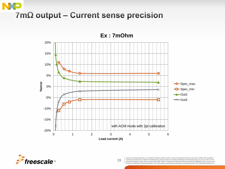
23 TM
-20%
-15%
-10%
-5%
0%
5%
10%
15%
20%
0 1 2 3 4 5 6
%err
or
Load current (A)
Ex : 7mOhm
Spec_max
Spec_min
Out3
Out3
with ACM mode with 2pt calibration

24 TM
Features Benefits
Lowest Rdson @ 6/10/20 m in thermally enhanced
package
Best thermal efficiency for 30% smaller footprint and best
module longevity with 30% lower power dissipation
3.3 / 5.0 V compatible 16-bit Daisy chainable SPI control BOM component & cost savings by eliminating series SPI
resistors between MCU and device
Compatible devices and flexible load management from
1 to 24A with possible parallel output operating modes
Hardware reuse across multiple applications and quick-turn
flexibility for tuning designs with ambiguous load requirement
Programmable dynamic threshold over-current and over-
temperature detection limits Optimized fault protection
Programmable fault auto-retry Auto recovery for transient faults
Full programmability and diagnostic capability through SPI Off loads real-time interrupt fault management from MCU,
simplifying system hardware and software
Accurate temperature (±5°C) and synchronous /
asynchronous current (±10%) sensing Advanced load diagnostics
Selectable slew rate Optimize EMI vs efficiency tradeoff
Individually programmable internal/external PWM signals Offloads MCU for software design simplicity & PPM reduction

25 TM
CONF bit = 0
Static Bulb lamp over-
current protection profile
activated
CONF bit = 1
Dynamic DC Motor over
current protection profile
activated
Dynamic over current protection window
protects DC motors without shutting down
the supply during short stall-periods
Activation by I(load) > I(OCL)
Static multi-stage over current protection
profile protects lamps without shutting down
the supply during inrush current
Activation by a turn-ON event
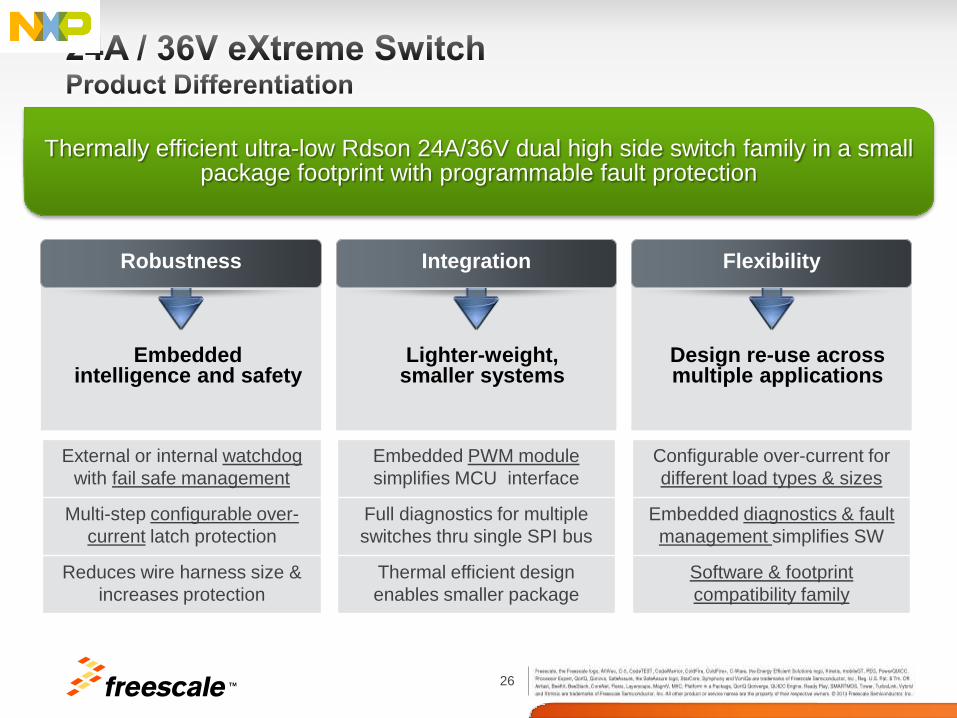
26 TM
Thermally efficient ultra-low Rdson 24A/36V dual high side switch family in a small package footprint with programmable fault protection
Embedded intelligence and safety
Lighter-weight, smaller systems
Design re-use across multiple applications
External or internal watchdog
with fail safe management
Multi-step configurable over-
current latch protection
Reduces wire harness size &
increases protection
Embedded PWM module
simplifies MCU interface
Full diagnostics for multiple
switches thru single SPI bus
Thermal efficient design
enables smaller package
Configurable over-current for
different load types & sizes
Embedded diagnostics & fault
management simplifies SW
Software & footprint
compatibility family
Robustness Integration Flexibility

27 TM
Freescale’s External Web Site http://www.freescale.com/ Freescale’s Analog Web Site (useful pdf’s plus links to other sites) http://www.freescale.com/webapp/sps/site/homepage.jsp?code=ANALOGHOME
About Freescale Analog Analog Technology Brochure (pdf) Analog Packaging Brochure (pdf) Analog Applications Brochure (pdf) Automotive Solutions Brochure (pdf) Analog Selector Guide (pdf) Automotive Selector Guide (pdf) SafeAssure Functional Safety Thermal Analysis of Semiconductor Systems (pdf)
High Side Switches, including eSwitches (parametric search & datasheets) http://www.freescale.com/webapp/sps/site/taxonomy.jsp?nodeId=01435979968459 Analog Toolbox (Evaluation Kits, SPIGEN software, reference designs) http://www.freescale.com/zh-Hans/webapp/sps/site/overview.jsp?code=ANALOGTOOLBOX SPI Generator (SPIGen) Software http://www.freescale.com/webapp/sps/site/prod_summary.jsp?code=SPIGEN

28 TM
• Evaluation kit (EVB kit)
KIT06XS4200EVBE for the Dual 6 mOhm device
KIT10XS4200EVBE for the Dual 10 mOhm device
KIT20XS4200EVBE for the Dual 20 mOhm device
• Reference design
16-bit MCU S12G, 4 eXtreme Switch devices, CAN Physical Layer, 5V regulator
• Application notes and tools MC06XS4200 / MC10XS4200 / MC20XS4200 Datasheets
AN2467: Power Quad Flat No-Lead (PQFN) Package
AN3298: Solder Joint Temperature and Package Peak Temperature
AN4516: IBIS Model File for Dual 24V High Side
AN4474: EMC and Fast Transient Pulses Performances for Dual 24 V High Side
AN4473: Compact Thermal Model for Dual 24V High Side Switch
AN4515: Lifetime Computation for Dual 24V High Side
AN4542: Repetitive Short-Circuit Performances for Dual 24V High Side
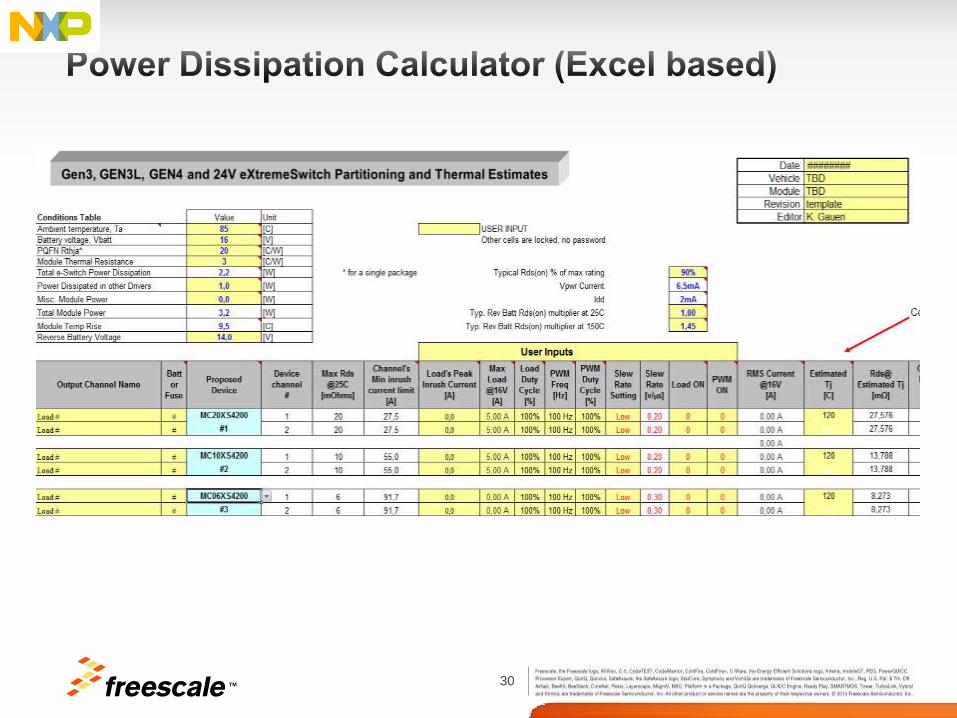
Microsoft Excel© Thermal Calculator
Cadence Orcad© Behavioral models
PLACEHOLDER
FOR IMAGE
Right click this shape/
format shape/
Picture or texture fill/
File/browse to image

29 TM
SPI communication
KITUSBSPIDGLEVME KIT06XS3400EVBE
Load 0
24V Power supply
5V Power supply
PC via USB Load 1
30 TM
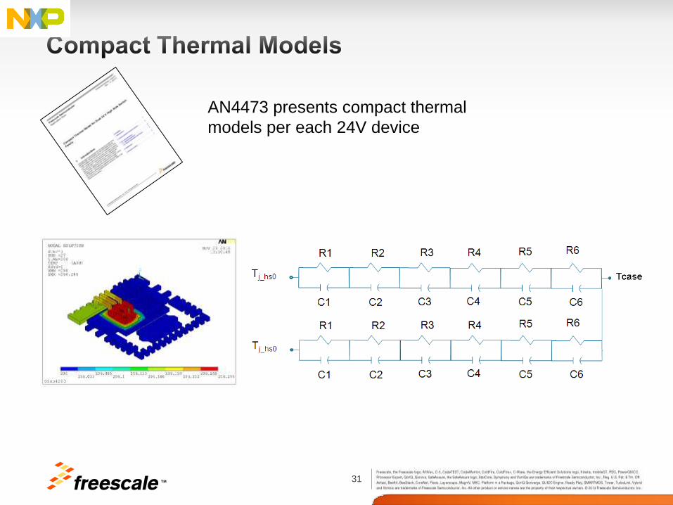
31 TM
AN4473 presents compact thermal
models per each 24V device

32 TM
IBIS file contains the basic signal models for each type of signal of device:
• For input buffers: Input's capacitance and static pull-up/down currents
• For output buffers: Output's capacitance, static/dynamic pull-up/down currents, propagation delay
For Dual 24 V High Side Switch, the IBIS model contains descriptions of
• 4 input buffers: CLOCK, SCLK, CSB, RSTB, SI, IN[0:1], CONF[0:1] pins
• 4 output buffers: FSB, SO, FSB, SYNC pins
• Package parasitic elements
AN4516 presents the Input/Output Buffer
Information Specification (IBIS) model

33 TM
AN2467 presents guidelines for printed circuit
board design and assembly

34 TM
- 12V Intelligent High Side Switches
- 24V Intelligent High Side Switches
Supported Software Design Resource: Processor Expert
(MCU Driver Suite)
Interact, Explore, Create
with Tower Geeks Online Community
(www.towergeeks.org)
Available Nov 2013

35 TM
Supported Software Design Resource: Processor Expert
(MCU Driver Suite)
- Voltage regulator with advanced functional safety
features
Join KINETIS channel partners strategy
Avnet with WiGo
Future with Intersil
Arrow with Cloud Connect
Available Nov 2013

36 TM
• Processor Expert
− Provides features that fully support design time configuration
• Configuration of Whole Device
− Configuration of targeted MCU / MPU / DSC
− Configuration of components selected by user needed in application
• Code Generator
− Able to generate both:
MCU Component Drivers code for any given configuration
MCU Initialization code (application specific)
• Basic Element of the Processor Expert is Embedded Component
− Components are seen as objects for customer fast enablement
and ease-of-use
Available Nov 2013

37 TM
37

38 TM
The behavioral model manages concurrently the electrical and thermal aspects. It allows evaluation of a device’s thermal performance under various conditions:
• Supply voltage
• PCB design layout
• Ambient temperature
• eXtreme Switch device type changes
• Parametric range steps (over-current level , under-voltage threshold)
The prediction of junction temperature elevation is based on the computation of transient power dissipation on dedicated channel. The reciprocal influence of junction temperature and on-state resistance of channel is modeled.

39 TM

40 TM
What is NOT included in the model?
• Digital SPI control and diagnostic
• Analog diagnostic
• Reverse battery protection
• EMC emission > 1MHz and susceptibility
• Parasitic and second order effects
• Aging
Each model is flexible and ready for integration of models
developed by final user, like loads, PCB, etc.

TM