High-resolution 3D weld toe stress analysis and ACPD ...
14
RESEARCH PAPER High-resolution 3D weld toe stress analysis and ACPD method for weld toe fatigue crack initiation S. Chaudhuri 1,2 & J. Crump 3 & P. A. S. Reed 1 & B. G. Mellor 1 Received: 31 August 2018 /Accepted: 29 July 2019 # The Author(s) 2019 Abstract Weld toe fatigue crack initiation is highly dependent on the local weld toe stress-concentrating geometry including any inherent flaws. These flaws are responsible for premature fatigue crack initiation (FCI) and must be minimised to maximise the fatigue life of a welded joint. In this work, a data-rich methodology has been developed to capture the true weld toe geometry and resulting local weld toe stress-field and relate this to the FCI life of a steel arc-welded joint. To obtain FCI lives, interrupted fatigue test was performed on the welded joint monitored by a novel multi-probe array of alternating current potential drop (ACPD) probes across the weld toe. This setup enabled the FCI sites to be located and the FCI life to be determined and gave an indication of early fatigue crack propagation rates. To understand fully the local weld toe stress-field, high-resolution (5 μm) 3D linear-elastic finite element (FE) models were generated from X-ray micro-computed tomography (μ-CT) of each weld toe after fatigue testing. From these models, approximately 202 stress concentration factors (SCFs) were computed for every 1 mm of weld toe. These two novel methodologies successfully link to provide an assessment of the weld quality and this is correlated with the fatigue performance. Keywords Weld fatigue . Weld geometry . Tomography . Fatigue life . Stress analysis . Fatigue crack initiation . 3D finite element analysis 1 Introduction and background 1.1 Weld toe geometry Stress-concentrating geometrical features inherent to welding are one of the primary causes of the low fatigue strengths of welded joints compared to the unwelded ma- terial. The stress-concentrating features can be broadly classified as macro- or micro-sized; the former considers the weld bead geometry as described by the plate thick- ness, leg attachment length and weld toe angle and radius (Fig. 1) whilst the latter considers weld toe flaws, which typically consist of undercuts and spatter. The role of the inherent flaws in fatigue crack initiation is similar to the behaviour of sharp notches in unwelded material [2] and it has been shown that [3] even in high-quality weld flaws can have depths of 0.1 mm. Due to the inherent inhomogeneity of welding process- es, varying weld toe geometries can result, and it is Recommended for publication by Commission XIII - Fatigue of Welded Components and Structures * S. Chaudhuri [email protected] J. Crump [email protected] P. A. S. Reed [email protected] B. G. Mellor [email protected] 1 Engineering Materials Research Group, Faculty of Engineering and the Environment, University of Southampton, Southampton, UK 2 National Structural Integrity Research Centre (NSIRC), TWI Ltd, Cambridge, UK 3 TWI Ltd, Cambridge, UK Welding in the World https://doi.org/10.1007/s40194-019-00792-3
Transcript of High-resolution 3D weld toe stress analysis and ACPD ...

RESEARCH PAPER
High-resolution 3D weld toe stress analysis and ACPD methodfor weld toe fatigue crack initiation
S. Chaudhuri1,2 & J. Crump3& P. A. S. Reed1
& B. G. Mellor1
Received: 31 August 2018 /Accepted: 29 July 2019# The Author(s) 2019
AbstractWeld toe fatigue crack initiation is highly dependent on the local weld toe stress-concentrating geometry including any inherentflaws. These flaws are responsible for premature fatigue crack initiation (FCI) and must be minimised tomaximise the fatigue lifeof a welded joint. In this work, a data-rich methodology has been developed to capture the true weld toe geometry and resultinglocal weld toe stress-field and relate this to the FCI life of a steel arc-welded joint. To obtain FCI lives, interrupted fatigue test wasperformed on the welded joint monitored by a novel multi-probe array of alternating current potential drop (ACPD) probes acrossthe weld toe. This setup enabled the FCI sites to be located and the FCI life to be determined and gave an indication of earlyfatigue crack propagation rates. To understand fully the local weld toe stress-field, high-resolution (5 μm) 3D linear-elastic finiteelement (FE) models were generated from X-ray micro-computed tomography (μ-CT) of each weld toe after fatigue testing.From thesemodels, approximately 202 stress concentration factors (SCFs) were computed for every 1mmofweld toe. These twonovel methodologies successfully link to provide an assessment of the weld quality and this is correlated with the fatigueperformance.
Keywords Weld fatigue .Weld geometry . Tomography . Fatigue life . Stress analysis . Fatigue crack initiation . 3D finite elementanalysis
1 Introduction and background
1.1 Weld toe geometry
Stress-concentrating geometrical features inherent towelding are one of the primary causes of the low fatiguestrengths of welded joints compared to the unwelded ma-terial. The stress-concentrating features can be broadlyclassified as macro- or micro-sized; the former considersthe weld bead geometry as described by the plate thick-ness, leg attachment length and weld toe angle and radius(Fig. 1) whilst the latter considers weld toe flaws, whichtypically consist of undercuts and spatter. The role of theinherent flaws in fatigue crack initiation is similar to thebehaviour of sharp notches in unwelded material [2] and ithas been shown that [3] even in high-quality weld flawscan have depths of 0.1 mm.
Due to the inherent inhomogeneity of welding process-es, varying weld toe geometries can result, and it is
Recommended for publication by Commission XIII - Fatigue of WeldedComponents and Structures
* S. [email protected]
P. A. S. [email protected]
B. G. [email protected]
1 Engineering Materials Research Group, Faculty of Engineering andthe Environment, University of Southampton, Southampton, UK
2 National Structural Integrity Research Centre (NSIRC), TWI Ltd,Cambridge, UK
3 TWI Ltd, Cambridge, UK
Welding in the Worldhttps://doi.org/10.1007/s40194-019-00792-3
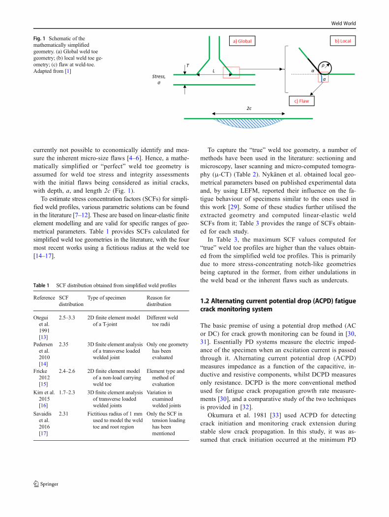
currently not possible to economically identify and mea-sure the inherent micro-size flaws [4–6]. Hence, a mathe-matically simplified or “perfect” weld toe geometry isassumed for weld toe stress and integrity assessmentswith the initial flaws being considered as initial cracks,with depth, a, and length 2c (Fig. 1).
To estimate stress concentration factors (SCFs) for simpli-fied weld profiles, various parametric solutions can be foundin the literature [7–12]. These are based on linear-elastic finiteelement modelling and are valid for specific ranges of geo-metrical parameters. Table 1 provides SCFs calculated forsimplified weld toe geometries in the literature, with the fourmost recent works using a fictitious radius at the weld toe[14–17].
To capture the “true” weld toe geometry, a number ofmethods have been used in the literature: sectioning andmicroscopy, laser scanning and micro-computed tomogra-phy (μ-CT) (Table 2). Nykänen et al. obtained local geo-metrical parameters based on published experimental dataand, by using LEFM, reported their influence on the fa-tigue behaviour of specimens similar to the ones used inthis work [29]. Some of these studies further utilised theextracted geometry and computed linear-elastic weldSCFs from it; Table 3 provides the range of SCFs obtain-ed for each study.
In Table 3, the maximum SCF values computed for“true” weld toe profiles are higher than the values obtain-ed from the simplified weld toe profiles. This is primarilydue to more stress-concentrating notch-like geometriesbeing captured in the former, from either undulations inthe weld bead or the inherent flaws such as undercuts.
1.2 Alternating current potential drop (ACPD) fatiguecrack monitoring system
The basic premise of using a potential drop method (ACor DC) for crack growth monitoring can be found in [30,31]. Essentially PD systems measure the electric imped-ance of the specimen when an excitation current is passedthrough it. Alternating current potential drop (ACPD)measures impedance as a function of the capacitive, in-ductive and resistive components, whilst DCPD measuresonly resistance. DCPD is the more conventional methodused for fatigue crack propagation growth rate measure-ments [30], and a comparative study of the two techniquesis provided in [32].
Okumura et al. 1981 [33] used ACPD for detectingcrack initiation and monitoring crack extension duringstable slow crack propagation. In this study, it was as-sumed that crack initiation occurred at the minimum PD
Table 1 SCF distribution obtained from simplified weld profiles
Reference SCFdistribution
Type of specimen Reason fordistribution
Oteguiet al.1991[13]
2.5–3.3 2D finite element modelof a T-joint
Different weldtoe radii
Pedersenet al.2010[14]
2.35 3D finite element analysisof a transverse loadedwelded joint
Only one geometryhas beenevaluated
Fricke2012[15]
2.4–2.6 2D finite element modelof a non-load carryingweld toe
Element type andmethod ofevaluation
Kim et al.2015[16]
1.7–2.3 3D finite element analysisof transverse loadedwelded joints
Variation inexaminedwelded joints
Savaidiset al.2016[17]
2.31 Fictitious radius of 1 mmused to model the weldtoe and root region
Only the SCF intension loadinghas beenmentioned
Fig. 1 Schematic of themathematically simplifiedgeometry. (a) Global weld toegeometry; (b) local weld toe ge-ometry; (c) flaw at weld-toe.Adapted from [1]
Weld World

signal and that subsequent increases in PD were related tocrack extension. Venkatasubramanian and Unvala [34]
discussed the use of ACPD for crack length measurementsand highlighted the impact of the positioning and joiningof current and voltage probes and leads, in addition to theinfluence of stress on ACPD. Gibson [35] alsoemphasised the impact of stress on the PD signal. Testsdone by Raujol-Veillé et al. [25] used a digital ACPDsystem developed by MATELECT Ltd. to detect the sizeof fatigue cracks at the weld toe of their low alloy steelnon-load carrying joints. A combination of both ACPDand DCPD has been used by Wojcik et al. [36] for creepdamage monitoring and end of life warning for high-temperature components.
ACPD has been used in this study due to its character-istic “skin effect” [32, 34, 36], which causes the excitationcurrent to flow close to the surface of the specimen, asopposed to flowing uniformly through the cross-section inDCPD. The distance of the current from the surface,called skin depth, is a function of the frequency of thealternating current, with the skin depth decreasing (i.e.closer to the surface) with an increase in frequency. Thiseffect can be used to detect small surface breaking flawsor cracks initiating at the surface; it has been used for thelatter in this work. The equipment used for this test isfrom the same manufacturer MATELECT Ltd. as in [25,34–36].
1.3 Summary
The work presented in this paper describes the develop-ment of a process that combines state-of-the-art tech-niques available: to non-destructively resolve the “true”weld toe profile of non-load carrying welds, producehigh-resolution weld toe SCF distributions and identifycrack initiation under fatigue cycling using ACPD. This
Table 3 SCF distribution obtained for true weld profiles
Reference SCF distribution Resolution Type of specimen
Branco et al.1999 [18]
1.098–1.624(distribution ofmaximum SCFfrom differentspecimens)
37.5–60 μm 3D FE model ofbutt-welded andtransversenon-load carry-ing fillet-weldedjoints
Hou 2007 [19] 1.9–4.0, only 2%of all SCFsabove 3.0.Values aremaximumvalues at eachlocation alongthe weld toe
25 μm 3D FE model ofnon-load carry-ing cruciformjoint
Alam et al. 2010[21]
Mean SCF 3.09.SCF > 4ignored
0.92 μm 2D FE model oflaserhybrid-weldedeccentric filletjoints
J. Raujol-Veilléet al. 2015[25]
Normalised SCFrelative to meanSCF provided
10−3 relativeto flangethickness
3D FE model ofwelded T-joints
Crump 2017 [1] 2.45–8.70(distribution ofmaximum SCFsobtained foreach section)
10 μm 2D FE model oftransversenon-load carry-ing fillet-weldedjoints
Lener et al. 2018[28]
4.0 (maximumSCF)
50 μm 3D FE model ofT-joint (trans-verse non-loadcarryingfillet-weldedjoint)
Table 2 Methods used forcapturing the true weld profile Reference Methods used
Otegui et al. 1991 [13] Sectioning and rubber replica
Branco et al. 1999 [18] Sectioning and video monitoring system
Hou 2007 [19] 3D laser scanning technology
Lee et al. 2009 [20] Rubber moulding/replica
Alam et al. 2010 [21] Rubber replica and 3D optical profiler
Barsoum et al. 2011 [22] Silicone replica and vision system (3D surface capture)
Harati et al. 2015 [23] Weld impression analysis (WIA) [23, 24]
J. Raujol-Veillé et al. 2015 [25] Laser measurements
Lang et al. 2016 [26, 27] FARO mobile laser scan system
Crump 2017 [1] X-ray micro-computed tomography (μ-CT)
Lener et al. 2018 [28] FARO mobile laser scan system
Weld World

approach could lead to an evaluation of the effect of the“true” weld toe geometry on the fatigue performance of agood quality manual arc-welded joint using the fatiguenotch strain approach [37]. However, this is beyond thescope of this paper and will be discussed in a futurepublication.
2 Methodology
2.1 Material and specimen
A structural C-Mn steel (complying to BS EN10025-2 S355J2+N [39]) double-sided transverse non-load carrying joint oflength 500 mmwas manufactured by metal active gas (MAG)welding. For the work described in this paper, specimens ofwidth 50 mm were extracted from the welded plate avoidingstop/start locations, the full dimensions of which are given inFig. 2. Mechanical properties of the parent steel are providedin Table 4.
2.2 Experimental methods
2.2.1 Multi-probe ACPD crack monitoring
One weld toe on the specimen was equipped with a seriesof ACPD probes to detect early fatigue crack initiationand monitor early fatigue crack growth. The remainingthree weld toes were ultrasonically peened to delay fa-tigue crack initiation.
Load-control fatigue testing was carried out in tensionat a load ratio (R) of 0.1, frequency of 5 Hz and stressrange of 270 MPa in a Mayes servo-hydraulic test
machine. A schematic of the test setup is shown inFig. 3a, and an image of the specimen in the test machineis shown in Fig. 3b.
The multi-probe ACPD setup developed in this workutilised a MATELECT® CGM-7 ACPD Crack GrowthMonitor. An array of “active” PD probe pairs was posi-tioned along the weld toe with each probe pair posi-tioned at 4 mm intervals and corresponding “reference”probe pairs were positioned 10 mm below each “active”pair in the parent metal (Fig. 4). Reference probes wereused to account for changes in the test environment andsetup that can influence the instantaneous PD readings,i.e. temperature and current dissipation. For this work,however, the data from the reference probes were notused in the analysis described in the next section. Allthe wires were twisted to minimise interference betweenthem.
PD probes were made from enamelled nickel wires andwere spot-welded to the specimen surface. Current wireswere insulated copper wires and were connected to stud-welded nickel wire. Nickel wires were used as they pro-vided the best stud weld connection with the steel speci-men. Current wires were positioned along the surface ofthe specimen to allow for an effect called current focus-sing, which increases the density of the current field alongthe surface. This maximises the skin effect described inSection 1.2, and, therefore, the sensitivity of the techniquefor the detection of small fatigue cracks at the weld toe. Aschematic of the arrangement is shown in Fig. 5 and animage in Fig. 6. An AC current of 2 A at a frequency of20 kHz was used.
The fatigue test was interrupted (stopped) after a targetPD change of 2 mV at one “active” probe pair was ob-served. The value of 2 mV is based on the work ofRaujol-Veillé [25] using MATELECT® ACPD crackgrowth monitoring equipment with an AC current of1 A and a frequency of 20 kHz on a fillet weld. Raujol-Veillé used a single probe in his work and a change of2 mV represented a weld toe crack depth of 500 μm. Thework herein used a larger current to increase the sensitiv-ity of the ACPD technique.
Fig. 2 (a) Micrograph of thespecimen; (b) fatigue specimengeometry
Table 4 Mechanical properties of the base metal
Proof strength (MPa) UTS (MPa) Elongation (%)
464 602 25
Weld World

2.2.2 X-ray micro-computed tomography and finite elementanalysis
A 5 × 5 × 50 mm specimen consisting of the weld toewas extracted from the fatigue tested specimen usingelectrical discharge machining (EDM). The entire spec-imen was then scanned using non-destructive X-raymicro-computed tomography (μCT) at the Universityof Southampton’s μVIS Imaging Centre using the
HMX system. Nine thousand seven hundred eight radio-graphs were generated during the scan, which were re-constructed in three dimensions (3D) using CT Pro 3Dsoftware. Scan parameters were determined from [1]and are given in Table 5. In terms of the impact ofthe surrounding weld bead geometry and base metalon the weld toe stresses, it has been seen before [1]that geometry beyond a distance of 2 mm has no sig-nificant impact.
Fig. 3 (a) Schematic of specimensetup; (b) image of the specimenin the servo-hydraulic testmachine
Fig. 4 Schematic of ACPD probes layout (not drawn to scale) Fig. 5 Schematic of current wire layout (not drawn to scale)
Weld World

After 3D reconstruction, volumes were converted to aseries of 2D images. These were cropped to the region ofinterest to reduce file size (Fig. 7a) and then processed inImageJ® using the MinError(I) algorithm [38] (Fig. 7b).An algorithm was written in MATLAB® to extend eachimage, making it representative of the full weld bead (Fig.7c and d).
3D meshed models for finite element analysis (FEA)were created in Simpleware ScanIP™ software on imagestacks of 150 image slices, equivalent to 0.73 mm of weldtoe length. These sub-volume sizes were chosen to obtainfeasible meshing times (approximately 2 h). The stack ofbinary images shown in Fig. 7d was imported into the soft-ware. A 3D rendered sub-volume is shown in Fig. 8 (forμCT scan resolution of 4.9 μm). The entire 3D volume wasapproximately 46.5 mm long, which gave 64 sub-volumes.Each such sub-volume was separately meshed and solved.
A mesh validation study was performed to determinethe optimum mesh density that accurately describes thelocal weld toe geometry whilst still providing feasiblemeshing times. Mesh refinement was applied at the weldtoe using three concentric cylinders (Fig. 9). The re-maining material was assigned a maximum element sizeof 1.5 mm. Adaptive meshing using the +FE Free algo-rithm in Simpleware scanIP™ was used to create themesh.
Two kinds of mesh validation processes wereperformed:
1. Element size. In this mesh validation, the element sizein cylinder 1, the refinement zone enveloping theweld toe along the weld bead, was varied to obtainconvergence of SCF values obtained at the weld toe.The element size chosen was the same as the resolu-tion of the μCT scan. Table 6 shows the results of thisvalidation study.
2. Cylinder 1 radius. In this mesh validation, the radius ofcylinder 1 was varied. It was seen that a radius of0.2 mm gave feasible meshing time (approximately2 h) and convergent SCF results. Table 7 shows theresults of this validation study. Note that the meshingtime varies for each sub-model, depending on the com-plexity of the geometry in each model.
Based on these two types of mesh validation studies, thefinal mesh parameters were decided and are presented inTable 8. Figure 10 shows the final meshed weld toe geom-etry for one sub-volume containing a cold lap feature. Thismesh contains a total of 8.7 million elements and 1.5 millionnodes.
FE models (without sub-modelling) were created inABAQUS® using the orphan meshes exported fromSimpleware scanIP™. Boundary conditions were appliedto the model to replicate the fully tensile fatigue test set-up. A 3D static linear-elastic stress analysis was carriedout for each of the 64 sub-volumes to obtain the stressdistribution along the weld toe. Young’s modulus of207 GPa and Poisson’s ratio of 0.3 were used for thestress analysis. As the stress analysis was purely linear-elastic, no hardening effects and phase transformation ef-fects were considered. Due to the size of the models, allcomputing was performed on a high-performance comput-ing cluster facility at the University of Southampton.
Fig. 6 Specimen after ACPD wiring, ready for fatigue testing
Table 5 μ-CT scan settings
Scan parameter Setting
Target Reflection
Beam energy 200 kV
Beam intensity 175 μA
Filter material and thickness Tin, 0.25 mm
Exposure 0.177 s
Gain 5
Projections 1801
Frames per projection 16
Voxel size 4.9 μm
Approximate scan time 15 h
Weld World
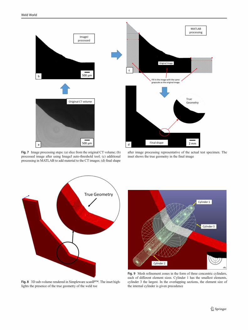
Fig. 7 Image processing steps: (a) slice from the original CT volume; (b)processed image after using ImageJ auto-threshold tool; (c) additionalprocessing in MATLAB to add material to the CT images; (d) final shape
after image processing representative of the actual test specimen. Theinset shows the true geometry in the final image
Fig. 8 3D sub-volume rendered in Simpleware scanIP™. The inset high-lights the presence of the true geometry of the weld toe
Fig. 9 Mesh refinement zones in the form of three concentric cylinders,each of different element sizes. Cylinder 1 has the smallest elements,cylinder 3 the largest. In the overlapping sections, the element size ofthe internal cylinder is given precedence
Weld World

3 Results and discussion
3.1 3D FE modelling
Weld toe SCFs were extracted from each FE model at5 μm and 50 μm intervals using an algorithm developedin MATLAB. Two SCFs were extracted: SCF11, the max-imum SCF in the x-direction (longitudinal to the parentmetal) and SCFPS, the maximum SCF in the principalstress direction. Example stress distributions from foursub-models exhibiting different geometries and stress dis-tributions are shown in Fig. 11. Regions with SCFs below1.0 are grey and SCFs above 4.0 are dark red; all imageshave the same scale.
Maximum SCF11 and SCFPS values for the length ofweld toe studied here (46.5 mm) are plotted in Fig. 12 at5 μm intervals. The maximum values are plotted as thereare multiple values of stress in any particular plane. TheACPD probe distribution along the weld toe has also beenshown in the image. Over 9300 SCF values were obtainedand statistically analysed to give the mean, median, range,interquartile range and standard deviation for the weldedsample (Table 9). A box-whisker plot showing the SCF11distribution is plotted in Fig. 13.
3.2 ACPD fatigue crack initiation monitoring
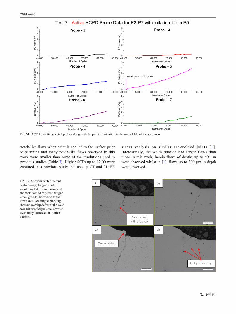
The interrupted fatigue test was performed to 84,344 cy-cles, which corresponded to a PD drop of 4 mV at Probe
5. PD drops (between 0.5 and 2 mV) were observed at sixof the other twelve PD probes; no PD drops were ob-served at the remaining five PD probes. To represent thisdata graphically, the absolute potential drop (PD) valuedetected by the probes is presented in Fig. 14 in millivolts(mV). Crack initiation life was evaluated based on theonset of PD drop in Probe 5. It is important to highlightthat crack initiation life has been defined as the number offatigue cycles to crack growth of a certain crack length ordepth, also referred to as a technical crack [37]. In thiswork, however, crack initiation life is defined by the in-dication obtained from the ACPD fatigue crack growthmonitoring technique.
3.3 Serial metallography results
Further validation of the work described thus far is pro-vided by serial metallography. This was conducted at re-gions of interest along the weld toe to capture the crackdepth and morphology to understand if it related well withthe FE and ACPD results. A controlled metallographymethodology was developed to remove material trans-verse to the weld toe at 50 μm and 200 μm intervals.The sections provided information on fatigue crack depth,
Table 6 Mesh validation type 1—cylinder 1 element size
Serial Cylinder 1 element size (μm) Maximum SCF
1 6 4.936
2 5.5 5.651
3 5.0 6.302
4 4.9 (μCT scan resolution) 6.396
5 4.0 6.431
Table 7 Mesh validation type 2—cylinder 1 radius
Serial Cylinder 1 radius (mm)Element size (5 μm)
Maximum SCF Meshing time
1 0.2 6.302 89 min
2 0.4 6.311 110 min
3 0.8 6.315 178 min
4 1.2 6.332 201 min
Table 8 Final mesh refinement parameters
Zone Cylinder1
Cylinder2
Cylinder3
Rest of themodel
Radius (mm) 0.2 0.3 1.0 NA
Element size(μm)
4.9 10.0 20.0 Up to 1500
Fig. 10 Final meshed sub-volume containing a cold lap feature at theweld toe
Weld World

Fig. 11 Example SCF11 distributions from four sub-models—(a) and (b) are examples with relatively lower stress concentration; (c) example of a coldlap defect; (d) example of a weld bead section with consistently large stress concentration across the weld toe
Fig. 12 SCF11 and SCFPS values plotted along the length of the weld toe
Weld World

crack morphology and the number of cracks. Figure 15features four such obtained sections. Figure 15(a) shows afatigue crack with bifurcation occurring possibly aroundgrains. Figure 15(c) shows a fatigue crack at an overlapdefect at the weld toe. Figure 15(d) shows the presence ofthree fatigue cracks that are growing on two differentplanes adjacent to each other. A total of 180 sections havebeen taken at regions of interest, to cover a total of ap-proximately 18 mm of the total weld toe length of46.5 mm. The crack depths of nine different cracks arerepresented along with the SCF11 distribution plot inFig. 16. 7.2.C, 7.3.SH.C and 7.3.LO.C represent themounts into which the specimen was cut for serialmetallography. The number after “.C” (for example 1 in7.2.C1) represents the serial number of the crack. Resultsfrom this plot will be further analysed in Section 3.4.
3.4 Validation of 3D finite element linear-elastic stressanalysis using ACPD and serial metallography
Figure 16 presents the observed crack depth at regionsidentified using the ACPD probe data in Fig. 14.
Multiple cracking was observed at the weld toe.Figure 17 contains two higher resolution plots from Fig.16 and are the regions subjected to serial metallography.Some smaller cracks, with depths between 5 and 50 μmand lengths (along the weld toe for which the crack wasobserved) between 20 and 200 μm, were removed fromthe plots for clarity. The deepest cracks are in the regionswith the maximum change in ACPD data. This area alsocorresponds to the area of consistently larger SCF11 ob-served in the FE analysis. It corresponds to a locationwhere two weld ripples meet to create a region ofstress-concentrating geometry. Crack depth is seen to fol-low the SCF distribution. However, the ACPD probes P2and P3 have not shown the same degree of change asprobes P4, P5 and P6. This could be due to the fact thatthe SCF distribution at P2 was lower than P5. No serialmetallographic evidence is available for P3. Also, P6 ex-perienced multiple cracking, which could explain the de-flection in measured PD voltage. The effects of stress onACPD potentially play a role as well, and further testingwould be required to investigate the exact effects. It isalso important to note that fatigue crack initiation is notalways associated with regions of higher SCFs, but alsooccurs at surface spatter which exhibited SCF11 from3.00-6.40.
Fatigue cracking (revealed from serial metallography) hasoccurred at the locations of high stress concentration observedin the 3D FE stress analysis. The ACPD probes informationused to indicate fatigue crack growth location and life havefurther validated this.
3.5 Discussion
The multiple probe ACPD system captured early fatiguecrack propagation at the weld toe and indicated the loca-tion of fatigue crack initiation. This gives the potential offocussing on the crack initiation sites at the weld toe infuture tests, and to obtain more information on the mostcritical weld toe geometries to fatigue. The qualitativedata obtained from continuous ACPD monitoring alsocorrelated well with the obtained SCF11 values and crackdepths measured from serial metallography. The correla-tion to crack depths indicated that the ACPD signal is alsolikely to be influenced by multiple cracking andneighbouring cracking and net section stresses.
The high (elastic) SCF values obtained in this work arelarger than most of those obtained in previous similarstudies in the literature [14–19, 21, 28]. This could beattributed to both the methods used for capturing the weldtoe geometry and the resolution. Some measurementmethods such as laser scanning are unable to captureFig. 13 Box and whisker plot for maximum SCF11 distribution
Table 9 Statistical analysis of the SCF values obtained
Statistical values SCF11 SCFPS
Mean 3.89 4.21
Median 3.71 4.03
Maximum 8.49 9.16
Minimum 2.03 2.04
1st quartile (25th percentile) 3.14 3.36
3rd quartile (75th percentile) 4.55 4.96
Standard deviation 0.94 1.05
Weld World
notch-like flaws when paint is applied to the surface priorto scanning and many notch-like flaws observed in thiswork were smaller than some of the resolutions used inprevious studies (Table 3). Higher SCFs up to 12.00 werecaptured in a previous study that used μ-CT and 2D FE
stress analysis on similar arc-welded joints [1].Interestingly, the welds studied had larger flaws thanthose in this work, herein flaws of depths up to 40 μmwere observed whilst in [1], flaws up to 200 μm in depthwere observed.
Fig. 14 ACPD data for selected probes along with the point of initiation in the overall life of the specimen
Fig. 15 Sections with differentfeatures—(a) fatigue crackexhibiting bifurcation located atthe weld toe; b) expected fatiguecrack growth–transverse to thestress axis; (c) fatigue crackingfrom an overlap defect at the weldtoe; (d) two fatigue cracks whicheventually coalesced in furthersections
Weld World

Fig. 16 Observed crack morphology and depths from serial metallography
Fig. 17 Plots A and B represent the crack depth with SCF11 distribution for the regions that have been subject to serial metallography
Weld World

4 Conclusion
& In this study, the weld toe profile has been resolved usingμ-CT at a resolution (< 5 μm) capable of capturing theinherent flaws. The 3D volumes have then been subjectedto a high-resolution FE stress analysis, the results of whichhave been linked to fatigue crack initiation and early crackpropagation data obtained from the joint using a multipleprobe ACPD method.
& SCF11 values ranging between 2.03 and 8.49 were obtain-ed for the weld studied in this work, which resulted infatigue crack depths up to 230 μm after 84,344 cycles ata stress range of 270 MPa and stress-ratio of 0.1. SCF11values correlated well with ACPD data and measuredcrack depths from serial metallography, and the resultsindicated that multiple cracking is likely to influence theACPD results though the data still provides a clear indi-cation of crack initiation below 0.25 mm.
& The methodology developed in this work provides a data-rich weld toe analysis method capable of linking the “true”weld toe stresses with fatigue crack initiation results andthus allowing for an improved assessment of welded jointsin the future.
Acknowledgements The authors would like to thank μVIS X-RayImaging Centre at the University of Southampton for performing themicro-computed tomography and providing access to essential softwareand high-performance computers, and Matthew Waitt and Adam WojcikfromMATELECT Ltd. for their support with the MATELECT® CGM-7ACPD system. The authors acknowledge the use of the IRIDIS High-Performance Computing Facility, and associated support services at theUniversity of Southampton, in the completion of this work.
Funding information The authors received financial support fromEPSRC (grant number EP/M508147/1), the University of Southampton,National Structural Integrity Research Centre (NSIRC) and TWI Ltd.which made their facilities available for this work.
Open Access This article is distributed under the terms of the CreativeCommons At t r ibut ion 4 .0 In te rna t ional License (h t tp : / /creativecommons.org/licenses/by/4.0/), which permits unrestricted use,distribution, and reproduction in any medium, provided you give appro-priate credit to the original author(s) and the source, provide a link to theCreative Commons license, and indicate if changes were made.
References
1. Crump J (2017) “A review and investigation on the effect ofwelding parameters on weld toe geometry, stresses and fatigue,”EngD Thesis, University of Southampton, Southampton, UK
2. Signes EF, Baker RG, Harrison JD, Burdekin FM (1967) Factorsaffecting the fatigue strength of welded high strength steels. BrWeld J:109–116
3. Grover (1987) “Initial flaw size estimating procedures for fatiguecrack growth calculations.” In International Conference on Fatigueof Welded Construction, Brighton, pp. 275–285
4. Meneghetti G, Marini D, Babini V (2016) Fatigue assessment ofweld toe and weld root failures in steel welded joints according tothe peak stress method. Welding in the World 60:559–572
5. Pang HLJ (1993) Analysis of weld toe profiles and weld toe cracks.International Journal of Fatigue 15:31–36
6. Yakubovskii VV, Valteris IJ (1989) “Geometrical parameters of buttand fillet welds and their influence on the welded joint fatigue life.”IIW Document XIII, pp. 1326–89
7. Hellier AK, Brennan FP, Carr DG (2014) Weld toe SCF and stressdistribution parametric equations for tension (membrane) loading.Adv Mater Res 891-892:1525–1530
8. Brennan FP, Dover WD, Karé RF, Hellier AK (1999) Parametricequations for T-butt weld toe stress intensity factors. Int J Fatigue21:1051–1062
9. Hobbacher A (1993) Stress intensity factors of welded joints. EngFract Mech 46:173–182
10. Niu X, Glinka G (1989) Stress-intensity factors for semi-ellipticalsurface cracks in welded joints. Int J Fract 40:255–270
11. Martins Ferreira JA, Moura Branco CA (1989) Influence of theradius of curvature at the weld toe in the fatigue strength of filletwelded joints. Int J Fatigue 11:29–36
12. Niu X, Glinka G (1987) The weld profile effect on stress intensityfactors in weldments. Int J Fract 35:3–20
13. Otegui JL, Burns DJ, Kerr HW, Mohaupt UH (1991) Growth andcoalescence of fatigue cracks at weld toes in steel. Int J Press VesselPip 48:129–165
14. Pedersen MM, Mouritsen OØ, Hansen MR, Andersen JG,Wenderby J (2010) Re-analysis of fatigue data for welded jointsusing the notch stress approach. Int J Fatigue 32:1620–1626
15. Fricke W (2012) IIW recommendations for the fatigue assessmentof welded structures by notch stress analysis: IIW-2006-09. IIWRecommendations for the Fatigue Assessment of WeldedStructures by Notch Stress Analysis, Woodhead Publishing, 2–41
16. Kim Y, Oh J-S, Jeon S-H (2015) Novel hot spot stress calculationsfor welded joints using 3D solid finite elements.Mar Struct 44:1–18
17. Savaidis G, Malikoutsakis M (2016) Advanced notch strain basedcalculation of S–N curves for welded components. Int J Fatigue 83:84–92
18. Branco CM, Maddox SJ, Infante V, Gomes EC (1999) Fatigueperformance of tungsten inert gas (TIG) and plasma welds in thinsections. Int J Fatigue 21:587–601
19. Hou C-Y (2007) Fatigue analysis of welded joints with the aid ofreal three-dimensional weld toe geometry. Int J Fatigue 29:772–785
20. Lee C-H, Chang K-H, Jang G-C, Lee C-Y (2009) Effect of weldgeometry on the fatigue life of non-load-carrying fillet welded cru-ciform joints. Eng Fail Anal 16:849–855
21. Alam MM, Barsoum Z, Jonsén P, Kaplan AFH, Häggblad HÅ(2010) The influence of surface geometry and topography on thefatigue cracking behaviour of laser hybrid welded eccentric filletjoints. Appl Surf Sci 256:1936–1945
22. Barsoum Z, Jonsson B (2011) Influence of weld quality on thefatigue strength in seam welds. Eng Fail Anal 18:971–979
23. Harati E, Karlsson L, Svensson LE, Dalaei K (2015) The relativeeffects of residual stresses and weld toe geometry on fatigue life ofweldments. Int J Fatigue 77:160–165
24. Harati E, Ottosson M, Karlsson L, Svensson L-E (2014) “Non-destructive measurement of weld toe radius using weld impressionanalysis, laser scanning profiling and structured light projectionmethods,” Presented at the first international conference weldingnon destructive testing, Tehran, Iran
25. Raujol-Veillé J, Thévenet D, Doudard C, Calloch S, Minnebo H(2015) Rapid method for low cycle fatigue properties: thicknesseffect on the fatigue crack initiation life of welded joints. FatigueFract Eng Mater Struct 38:1492–1506
26. Lang R, Lener G, Schmid J, Ladinek M (2016) Welded seam eval-uation based on 3D laser scanning – practical application of mobile
Weld World
laser scanning systems for surface analysis of welds – part 1.Stahlbau 85:336–343
27. Lang R, Lener G (2016) Application and comparison of determin-istic and stochastic methods for the evaluation of welded compo-nents’ fatigue lifetime based on real notch stresses. Int J Fatigue 93:184–193
28. Lener G, Lang R, Ladinek M, Timmers R (2018) A numericalmethod for determining the fatigue strength of welded joints witha significant improvement in accuracy. Procedia Eng 213:359–373
29. Nykänen T, Marquis G, Björk T (2009) A simplified fatigue assess-ment method for high quality welded cruciform joints. Int J Fatigue31:79–87
30. (2012) BS ISO 12108:2012: Metallic materials - Fatigue testing -Fatigue crack growthmethod. British Standards Institution, London
31. ASTM (2015) ASTM E647-15e1, standard test method for mea-surement of fatigue crack growth rates. ASTM International, WestConshohocken
32. Neçar M (2003) Detecting and measuring flaws using electric po-tential techniques. J Qual Maint Eng 9:160–175
33. Okumura N, Venkatasubramanian TV, Unvala BA, Baker TJ (1981)Application of AC potential drop technique to the determination ofR curves of tough ferritic steels. Eng Fract Mech 14:617–625
34. Venkatsubramanian TV, Unvala BA (1984) An AC potential dropsystem for monitoring crack length. J Phys E: Sci Instrum 17:765–771
35. Gibson GP (1987) The use of alternating current potential drop fordetermining J-crack resistance curves. Eng Fract Mech 26:213–222
36. Wojcik A, Waitt M, Santos AS (2017) The use of the potential droptechnique for creep damage monitoring and end of life warning forhigh temperature components. Mater High Temp 34:458–465
37. Radaj D, Sonsino CM, Fricke W (2006) Fatigue strength assess-ment of welded joints by local approaches, 2nd edn. WoodheadPublishing, Cambridge
38. Kittler J, Illingworth J (1986) Minimum error thresholding. PatternRecogn 19:41–47
39. BS EN 10025-2:2004: Hot rolled products of structural steels. Part2 - Technical delivery conditions for non-alloy structural steels.British Standards Institution, London (2004)
Publisher’s note Springer Nature remains neutral with regard tojurisdictional claims in published maps and institutional affiliations.
Weld World