High-quality and Resilient IPTV Multicast Architecture
20
High-quality and resilient IPTV multicast architecture Technical White Paper An overview of ResIP multicast architecture design guidelines
-
Upload
aniketdhage -
Category
Documents
-
view
17 -
download
2
description
Video Application Components and Architecture
Transcript of High-quality and Resilient IPTV Multicast Architecture
High-quality and resilientIPTV multicast architecture
Technical White Paper
An overview of ResIP multicastarchitecture design guidelines

High-quality and resilient IPTV multicast architecture – Technical White Paper2/20
Profit from emerging broad-band services for residentialcustomers.
Tested and verified engineer-ing excellence to providebest-in-class IPTV solutions.
Executive summary
Contents
2 Executive summary
4 Introduction
5 Meeting end user expectations for IPTV
6 Network aspects
9 Access network architecture
12 Core network design concepts
16 Conclusion
17 About Nokia Siemens Networksand Juniper Networks
19 Abbreviations
Nokia Siemens Networks and Juniper Networks have joined together to developand implement carrier-grade end-to-end Next Generation Network (NGN) solutionswith best-in-class QoS, reliability, management, and security.
The Resilient IP (ResIP) Certified solutions are the product of more than threeyears of joint solution development work focused on validating, optimizing, andcertifying IP solutions for voice, video, and data applications – end-to-end.
Nokia Siemens Networks and Juniper cooperate to provide a complete, optimizedResIP Certified IPTV solution. The ResIP Lab combines best-of-breed productswith design know-how to provide solutions that minimize technical deploymentrisks, ensure interoperability and scale. The end result is a quicker time to marketand an assured user experience for IPTV services.

The ResIP design for IPTVservices for efficient deploy-ments and reliability.
This document focuses on:
• Network aspects, which are influenced by the introduction of IPTV servicesregarding required bandwidth, reliability, network responsiveness, and QoS.
• Different access network architectures are described, focusing on the currentlydiscussed VLAN models.
• The Layer 2 control mechanism and how this tool improves dynamic QoSconcepts are described.
• Protocol Independent Multicast – Sparse Mode (PIM-SM), Protocol IndependentMulticast – Source Specific Multicast (PIM-SSM) or Point-to-Point MPLS LSPscan be used for distributing the IPTV content through the IP backbone.
Service providers can tailor the ResIP Certified solutions and engineering workto their specific network environment. Nokia Siemens Networks and JuniperNetworks offer professional network planning and implementation services to helpcarriers customize their IPTV solution.
3/20
Leverage expertise from twoindustry leaders.

High-quality and resilient IPTV multicast architecture – Technical White Paper4/20
Telecom operators around the world are facing the challenge of declining voicerevenues due to increased competition and the mass proliferation of mobilecommunications. In addition, cable TV operators are adding voice services totheir traditional cable offering, and are thus entering into the domain of telecom-munication carriers.
Studies have shown that end customers will pay for an attractive service bundlecomprising voice, video, and data, and prefer to have a single bill from a trustedoperator for all their service needs. Under these conditions, it has become manda-tory for the incumbent fixed line carriers to reposition themselves in the changedcompetitive landscape. There is a strong need to migrate from simple infrastruc-ture provider to a one-stop service provider.
The new business model for the carriers will be driven by the expectations of endusers for multimedia services. The operator’s network must be able to support themultimedia services requirements, i.e. the need to have voice, data, video on de-mand (VoD), and TV broadcast services. The success of service bundling isdependent on satisfying the expectations of the end user.
Early movers on the IPTV market have faced the risk of suffering from technicalbarriers and challenges. In several cases, technical issues have led to stalledprojects, incomplete service offerings, and unexpected quality degradation of theservices. This in turn has affected the acceptance of the triple-play services andresulted in negative impact on margins and increased customer churn.
Nokia Siemens Networks and Juniper Networks partner to develop completesolutions to help service providers to successfully introduce and grow triple-playservices. Expertise from both companies have been brought together in the ResIPLab to validate, optimize, and certify IP solutions that service providers can use todeliver VoIP trunking, triple-play, and now IPTV services with an assured quality ofexperience.
1. Introduction
Nokia Siemens Networksand Juniper Networksdemonstrate combined voiceand video expertise in thejoint ResIP Lab.
Innovative onlineentertainment andcommunication via TV.
2. Meeting end userexpectations for IPTV
Introduction of new services always involve a number of commercial and technicalrisks. The success of services is dependent on meeting the requirements and ex-pectations of end users. TV services have been available for a long time overlegacy infrastructures including terrestrial broadcast, cable networks, and satellite.End users have come to expect a level of service regarding availability, latency,and quality. Therefore, it is vital to keep the technical risks to a minimum and tomeet user expectations and needs. To make the IPTV services a success, it isrequired to establish IP networks that guarantee the quality of service (QoS) evenunder adverse network conditions.
End user requirements are driving the need for:
• assured quality of service in real time including fast interactive responsivenessand minimum number of visual and acoustic defects
• a broad portfolio of video service offerings such as broadcast TV, VoD, personalvideo recording, or time-shift TV and the availability of premium content
• high availability, i.e. no single point of failure and fast recovery mechanisms forsub-second failover times
• easy and convenient handling
In addition to the end user’s expectation, service providers need to reduce costs(from both the equipment point of view and the operational point of view) andincrease revenues. Network operators must:
• optimize the utilization of network resources in both unicast and multicastenvironments
• minimize operational efforts through advanced management tools and zero-touch provisioning recommendations
• be quicker to market with new services• be flexible and maintain investment protection to address a broad range ofaccess types, network architectures, aggregation technologies, and existingprotocol environments
User expectations alreadysettled by existingdistribution technologies.
ResIP Certified IPTVsolution provides carrierswith industry-leading broad-band video programs.
5/20
High-quality and resilient IPTV multicast architecture – Technical White Paper6/20
The introduction of IPTV services, including both broadcast TV and on-demandservices, onto today’s broadband IP networks changes several aspects of thesenetworks.
3.1. Bandwidth dimensioningIPTV and VoD services require high bandwidth capacities and predictable per-formance, placing additional requirements on the network. Depending on thecompression and coding technology, the following transmission rates should beconsidered:
• MPEG-2-coded SD VoD video streams or IPTV stream per one TV channel:3.5-5 Mbit/s
• H.264-coded (MPEG-4 part 10) SD VoD video streams or IPTV stream per oneTV channel: up to 2 Mbit/s
• HD signals will need 8-12 Mbit/s coded with H.264
IPTV and video services have different influences on available network resources.Several factors have to be considered before the implementation of an IPTVservice including:
Influence of broadcast TV (IPTV) servicesThe total number of IPTV channels streamed online determines the total band-width requirements. The total transmission rate of the IPTV content measured inMbit/s equals the sum of all concurrent streams. Each IPTV channel is sent onlyonce from the video headend to the network, independent of the number of po-tential TV broadcast receivers. The distribution to all subscribers is achieved bymulticast implementations in the core and the access networks. For example, if30 IPTV channels are broadcast and each channel is encoded by H.264 codecproviding a gross bit rate of 2 Mbit/s (incl. Ethernet overhead), 60 Mbit/s bandwidthis required for the IPTV service. The calculated 60 Mbit/s IPTV traffic will be trans-mitted via the network operator’s IP core network to the DSLAMs independent ofthe number of end customers. This amount of traffic does not affect the throughputof the IP core network dramatically.
In the core network, typically all offered IPTV channels are distributed withoutconsidering the current usage of every channel. However, in the access network,bandwidth can be reduced by supporting IGMP (Internet Group Multicast Protocol)snooping in the aggregation switches and edge routers. IGMP snooping can pas-sively snoop on IGMP Query, Report and Leave (IGMP version 2) packets trans-ferred between IP multicast routers/switches and IP multicast hosts to learn theIP multicast group membership. It checks IGMP packets passing through it, picksout the group registration information, and configures multicasting accordingly.Without IGMP snooping, multicast traffic is treated in the same manner as broad-cast traffic, that is, it is forwarded to all ports. With IGMP snooping, multicast trafficof a group is only forwarded to ports that have members of that group. IGMPsnooping with proxy reporting can help reduce the IGMP Membership Reportmessages.
Statistics in existing IPTV installations have shown that about 50% of all offeredchannels are requested by at least one user per DSLAM. This number dependson the ratio of free TV and pay TV channels or the quality of the electronicprogram guide (EPG).
3. Network aspects
Key elements of the ResIPCertified IPTV solution arethe design guidelines andthe proof-of-concept.
G1 G1
G2
G1+G2
G1+G2
IP edge IPTV edge
Resilientaggregation
IP core
G2
G1
G2
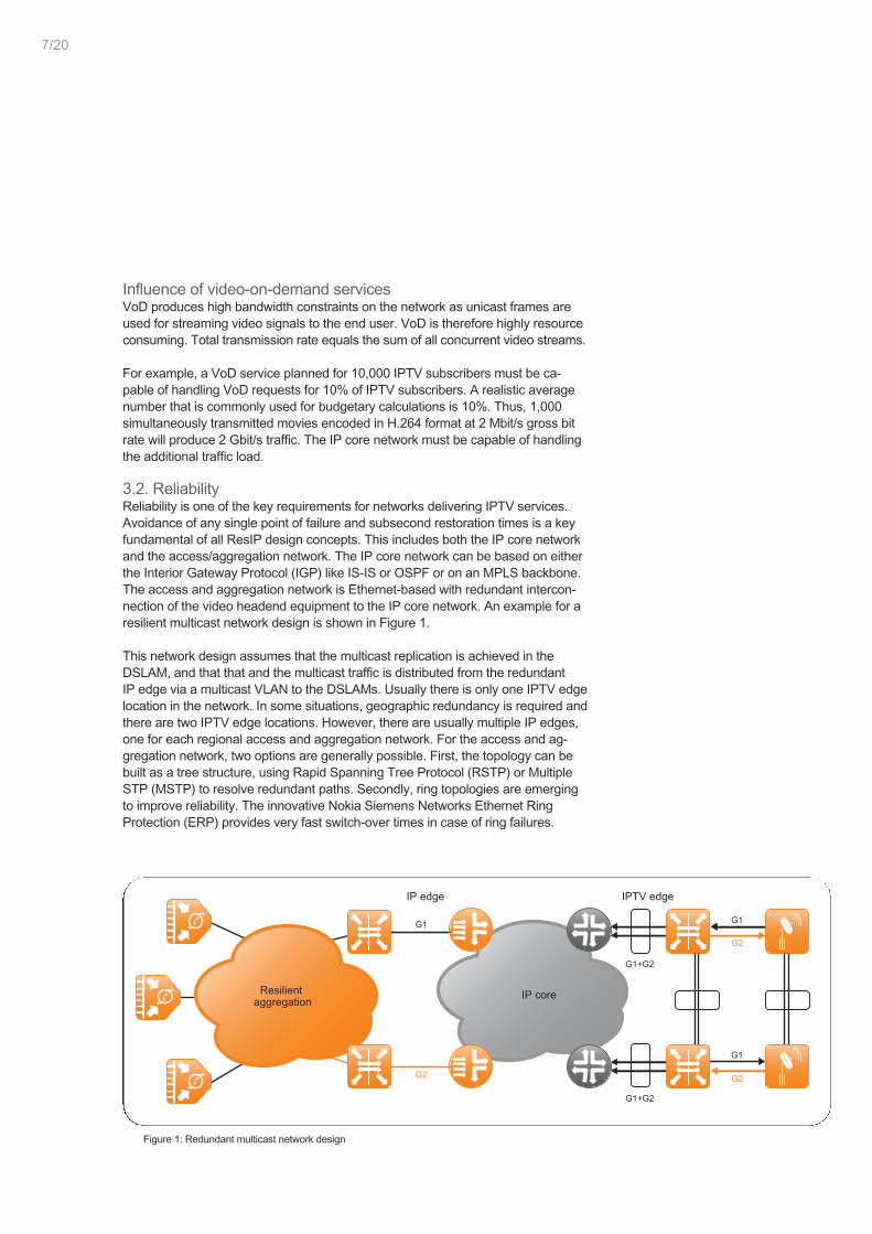
Figure 1: Redundant multicast network design
7/20
Influence of video-on-demand servicesVoD produces high bandwidth constraints on the network as unicast frames areused for streaming video signals to the end user. VoD is therefore highly resourceconsuming. Total transmission rate equals the sum of all concurrent video streams.
For example, a VoD service planned for 10,000 IPTV subscribers must be ca-pable of handling VoD requests for 10% of IPTV subscribers. A realistic averagenumber that is commonly used for budgetary calculations is 10%. Thus, 1,000simultaneously transmitted movies encoded in H.264 format at 2 Mbit/s gross bitrate will produce 2 Gbit/s traffic. The IP core network must be capable of handlingthe additional traffic load.
3.2. ReliabilityReliability is one of the key requirements for networks delivering IPTV services.Avoidance of any single point of failure and subsecond restoration times is a keyfundamental of all ResIP design concepts. This includes both the IP core networkand the access/aggregation network. The IP core network can be based on eitherthe Interior Gateway Protocol (IGP) like IS-IS or OSPF or on an MPLS backbone.The access and aggregation network is Ethernet-based with redundant intercon-nection of the video headend equipment to the IP core network. An example for aresilient multicast network design is shown in Figure 1.
This network design assumes that the multicast replication is achieved in theDSLAM, and that that and the multicast traffic is distributed from the redundantIP edge via a multicast VLAN to the DSLAMs. Usually there is only one IPTV edgelocation in the network. In some situations, geographic redundancy is required andthere are two IPTV edge locations. However, there are usually multiple IP edges,one for each regional access and aggregation network. For the access and ag-gregation network, two options are generally possible. First, the topology can bebuilt as a tree structure, using Rapid Spanning Tree Protocol (RSTP) or MultipleSTP (MSTP) to resolve redundant paths. Secondly, ring topologies are emergingto improve reliability. The innovative Nokia Siemens Networks Ethernet RingProtection (ERP) provides very fast switch-over times in case of ring failures.
High-quality and resilient IPTV multicast architecture – Technical White Paper8/20
3.3. Quality of serviceIPTV is a real-time service that has very stringent QoS requirements, specificallypacket loss and delay. A small amount of delay does not directly affect the qualityof experience of IPTV. However, a delay longer than 1 second may result in a lessthan satisfying end user experience if a neighbor with traditional TV service is ableto watch a goal in an important soccer game several seconds in advance. Packetloss will likely cause visible artifacts due to the high compression rates of MPEGencoded TV signals. In order to have less than one visible artifact per movie onthe TV screen, the packet loss rate must be lower than 10-6.
As quality of service is a comprehensive subject in the network design, a separatedocument will highlight the ResIP QoS recommendations for IPTV.
3.4. Network responsivenessOne prominent aspects of a good user experience for IPTV services includesfast channel change (also known as zapping). Channel change delay, i.e. thetime between pushing the remote control button and the first video frame beingrendered on the viewing device, is mainly influenced by the following:
• processing of the remote control request• IGMP control processing (set-top box (STB), residential gateway, network)• data plane protocol stack processing, including DSL interleaving delay, de-cryption, FEC, etc.
• STB jitter buffer delay• Buffer for video encoding• MPEG decoder delay for resynchronizing with the new program
The latency of IGMP processing in the network (e.g. the residential gateway,DSLAM and BSR) also directly adds to the overall zapping delay.
The required size of the jitter buffer depends on the jitter of the media stream re-ceived by the STB. The jitter generated by a well-engineered high bandwidth IPnetwork is less than 50 ms. The video source itself should also produce low jitterstreams.
MPEG decoder delay usually makes up the largest part of the overall delaybudget, because the decoder must usually wait for an I-frame to resynch. Also,additional decoding delay results due to the use of B-frames which are encodedusing past and future I- and P-frames. This delay depends on the compressionrate, the encoding algorithm and the number of B- and P-frames between twoI-frames (GOP). This results in a tradeoff between channel change delay andcompression rate. High compression rates imply a large GOP with extensive useof B-frames, and therefore result in a large encoding/decoding delay.
To improve the responsiveness from a user’s perspective, the STB immediatelyshows a dialogue box with the program name, time, channel, etc. upon receiving azapping request for another channel via the remote control. This ensures that endusers will never view a black screen while waiting.
The DSL Forum has recently finished the specification (TR-101) for the fundamen-tal architecture for Ethernet-based DSL aggregation networks, which also includesdefinitions for the delivery of multicast services.
Experience, knowledge andleadership – ResIP CertifiedIPTV solution.
4. Access networkarchitecture
TR-101 differentiates between two different approaches for connecting broadbandDSL users to the aggregation network, first the so-called 1:1 (also known as VLANper subscriber) and secondly the N:1 (also known as VLAN per service) mode.
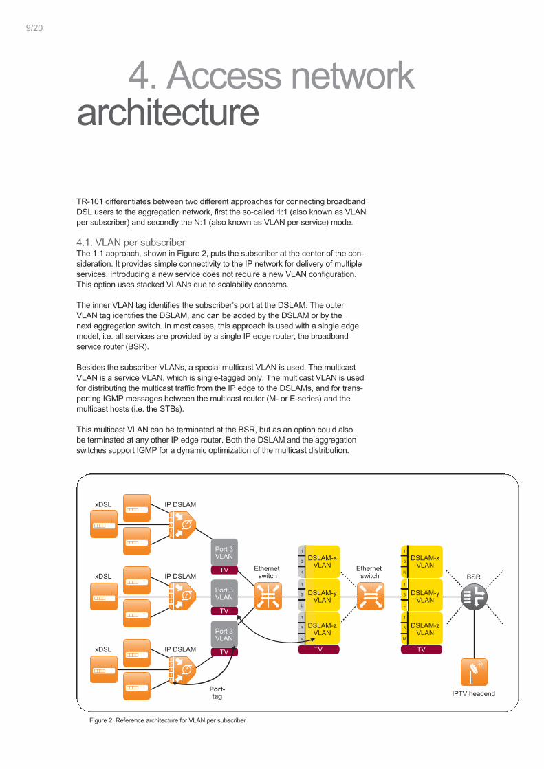
4.1. VLAN per subscriberThe 1:1 approach, shown in Figure 2, puts the subscriber at the center of the con-sideration. It provides simple connectivity to the IP network for delivery of multipleservices. Introducing a new service does not require a new VLAN configuration.This option uses stacked VLANs due to scalability concerns.
The inner VLAN tag identifies the subscriber’s port at the DSLAM. The outerVLAN tag identifies the DSLAM, and can be added by the DSLAM or by thenext aggregation switch. In most cases, this approach is used with a single edgemodel, i.e. all services are provided by a single IP edge router, the broadbandservice router (BSR).
Besides the subscriber VLANs, a special multicast VLAN is used. The multicastVLAN is a service VLAN, which is single-tagged only. The multicast VLAN is usedfor distributing the multicast traffic from the IP edge to the DSLAMs, and for trans-porting IGMP messages between the multicast router (M- or E-series) and themulticast hosts (i.e. the STBs).
This multicast VLAN can be terminated at the BSR, but as an option could alsobe terminated at any other IP edge router. Both the DSLAM and the aggregationswitches support IGMP for a dynamic optimization of the multicast distribution.
Figure 2: Reference architecture for VLAN per subscriber
9/20
TV
1234K
1234L
1234M
Port 3VLAN
TV
TV
Port 3VLAN
Port 3VLAN
TV
TV
DSLAM-xVLAN
1
3
K
1
3
L
1
3
M
DSLAM-zVLAN
DSLAM-yVLAN
IP DSLAMxDSL
xDSL
xDSL
IP DSLAMEthernet
switchEthernet
switch
Port-tag
BSR
IPTV headend
IP DSLAM
DSLAM-xVLAN
1
3
K
1
3
L
1
3
M
DSLAM-yVLAN
DSLAM-zVLAN
High-quality and resilient IPTV multicast architecture – Technical White Paper10/20
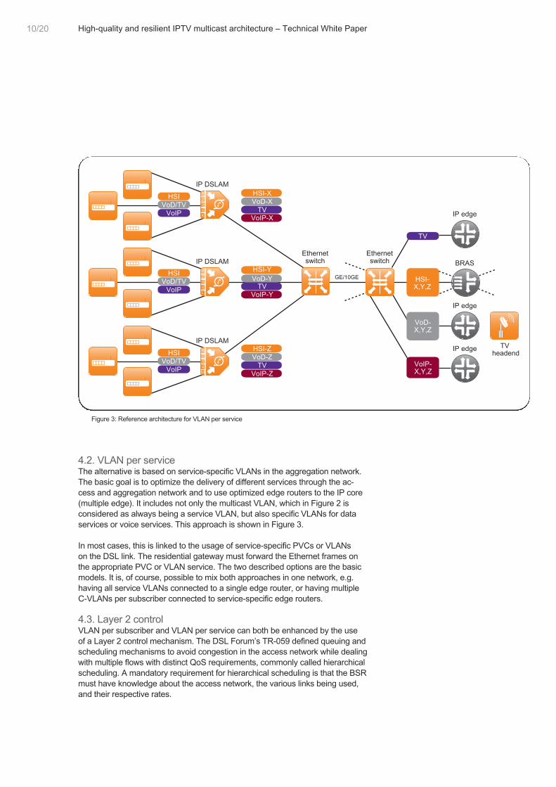
4.2. VLAN per serviceThe alternative is based on service-specific VLANs in the aggregation network.The basic goal is to optimize the delivery of different services through the ac-cess and aggregation network and to use optimized edge routers to the IP core(multiple edge). It includes not only the multicast VLAN, which in Figure 2 isconsidered as always being a service VLAN, but also specific VLANs for dataservices or voice services. This approach is shown in Figure 3.
In most cases, this is linked to the usage of service-specific PVCs or VLANson the DSL link. The residential gateway must forward the Ethernet frames onthe appropriate PVC or VLAN service. The two described options are the basicmodels. It is, of course, possible to mix both approaches in one network, e.g.having all service VLANs connected to a single edge router, or having multipleC-VLANs per subscriber connected to service-specific edge routers.
4.3. Layer 2 controlVLAN per subscriber and VLAN per service can both be enhanced by the useof a Layer 2 control mechanism. The DSL Forum’s TR-059 defined queuing andscheduling mechanisms to avoid congestion in the access network while dealingwith multiple flows with distinct QoS requirements, commonly called hierarchicalscheduling. A mandatory requirement for hierarchical scheduling is that the BSRmust have knowledge about the access network, the various links being used,and their respective rates.
1234K
1234L
1234M
IP DSLAM
IP DSLAM
GE/10GE
Ethernetswitch
Ethernetswitch
IP edge
BRAS
IP edge
TVheadend
IP edgeIP DSLAM
HSIVoD/TV
VoIP
HSI
TV
VoD/TVVoIP
HSI-XVoD-X
TVVoIP-X
TVVoD-Y
VoIP-Y
HSI-Y
VoIP-Z
HSI-ZVoD-Z
TV
HSIVoD/TV
VoIPVoIP-X,Y,Z
VoD-X,Y,Z
HSI-X,Y,Z
Figure 3: Reference architecture for VLAN per service
1234K
1234L
1234M
TV
IP DSLAMxDSL
xDSL
xDSL
IP DSLAMEthernet
switchEthernet
switch
BSR
IPTV headend
Multicast andshaping/subscr.
IP DSLAM
Multicastreplication
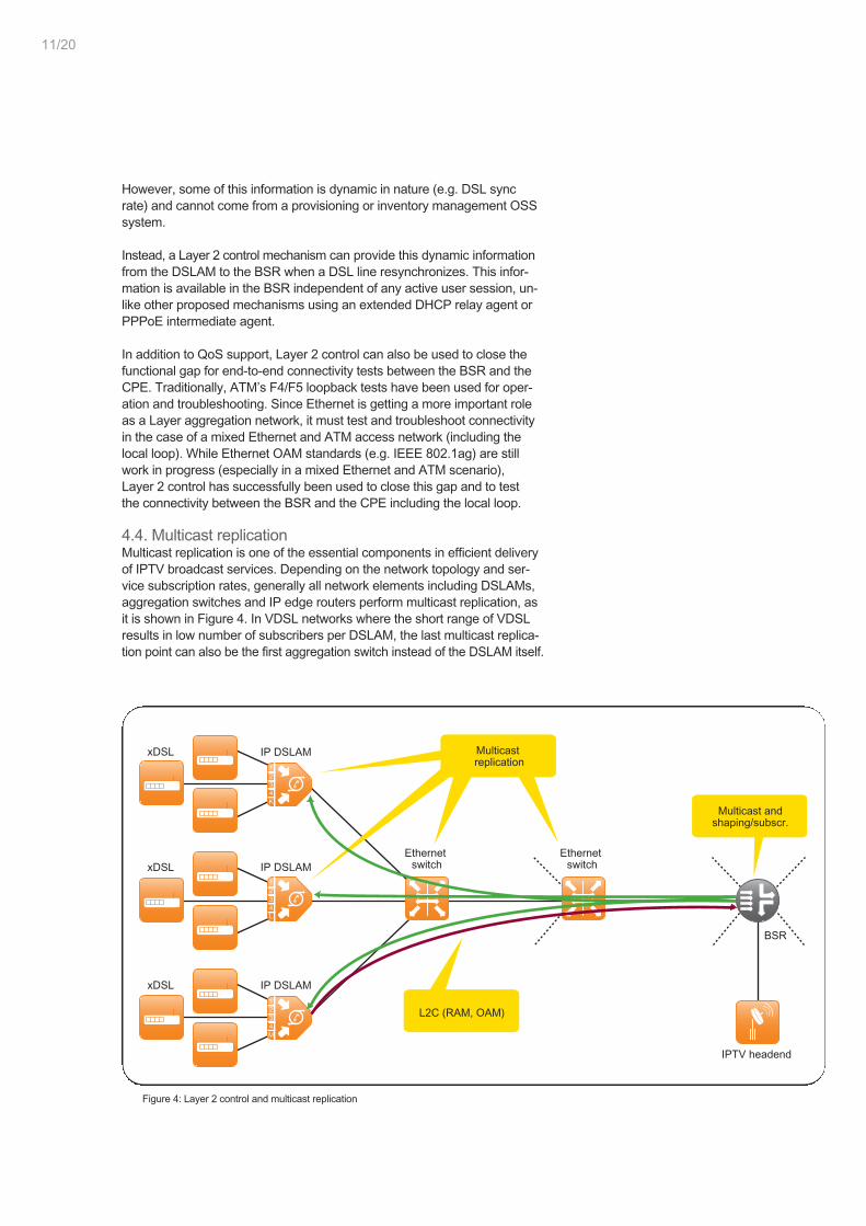
L2C (RAM, OAM)
Figure 4: Layer 2 control and multicast replication
However, some of this information is dynamic in nature (e.g. DSL syncrate) and cannot come from a provisioning or inventory management OSSsystem.
Instead, a Layer 2 control mechanism can provide this dynamic informationfrom the DSLAM to the BSR when a DSL line resynchronizes. This infor-mation is available in the BSR independent of any active user session, un-like other proposed mechanisms using an extended DHCP relay agent orPPPoE intermediate agent.
In addition to QoS support, Layer 2 control can also be used to close thefunctional gap for end-to-end connectivity tests between the BSR and theCPE. Traditionally, ATM’s F4/F5 loopback tests have been used for oper-ation and troubleshooting. Since Ethernet is getting a more important roleas a Layer aggregation network, it must test and troubleshoot connectivityin the case of a mixed Ethernet and ATM access network (including thelocal loop). While Ethernet OAM standards (e.g. IEEE 802.1ag) are stillwork in progress (especially in a mixed Ethernet and ATM scenario),Layer 2 control has successfully been used to close this gap and to testthe connectivity between the BSR and the CPE including the local loop.
4.4. Multicast replicationMulticast replication is one of the essential components in efficient deliveryof IPTV broadcast services. Depending on the network topology and ser-vice subscription rates, generally all network elements including DSLAMs,aggregation switches and IP edge routers perform multicast replication, asit is shown in Figure 4. In VDSL networks where the short range of VDSLresults in low number of subscribers per DSLAM, the last multicast replica-tion point can also be the first aggregation switch instead of the DSLAM itself.
11/20
High-quality and resilient IPTV multicast architecture – Technical White Paper12/20
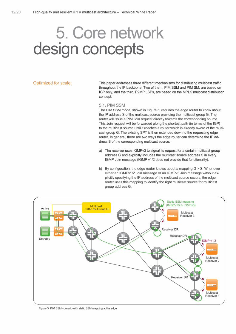
This paper addresses three different mechanisms for distributing multicast trafficthroughout the IP backbone. Two of them, PIM SSM and PIM SM, are based onIGP only, and the third, P2MP LSPs, are based on the MPLS multicast distributionconcept.
5.1. PIM SSMThe PIM SSM mode, shown in Figure 5, requires the edge router to know aboutthe IP address S of the multicast source providing the multicast group G. Therouter will issue a PIM Join request directly towards the corresponding source.This Join request will be forwarded along the shortest path (in terms of the IGP)to the multicast source until it reaches a router which is already aware of the multi-cast group G. The existing SPT is then extended down to the requesting edgerouter. In general, there are two ways the edge router can determine the IP ad-dress S of the corresponding multicast source:
a) The receiver uses IGMPv3 to signal its request for a certain multicast groupaddress G and explicitly includes the multicast source address S in everyIGMP Join message (IGMP v1/2 does not provide that functionality).
b) By configuration, the edge router knows about a mapping G > S. Whenevereither an IGMPv1/2 Join message or an IGMPv3 Join message without ex-plicitly specifying the IP address of the multicast source occurs, the edgerouter uses this mapping to identify the right multicast source for multicastgroup address G.
5. Core networkdesign concepts
Optimized for scale.
Standby
ActiveMulticast
traffic for Group G
Static SSM mapping(IMGPv1/2 > IGMPv3)
Receiver DR
Receiver DR
Receiver DR
IGMP v1/2
MulticastReceiver 2
MulticastReceiver 3
MulticastReceiver 1
Figure 5: PIM SSM scenario with static SSM mapping at the edge
Standby
ActiveMulticast
traffic for Group G
RPT for (*,G)but not for (S,G)
SPTs for (S,G)
Receiver DRReceiver DR
Receiver DR
MulticastReceiver 2
MulticastReceiver 3
MulticastReceiver 1
Register messages
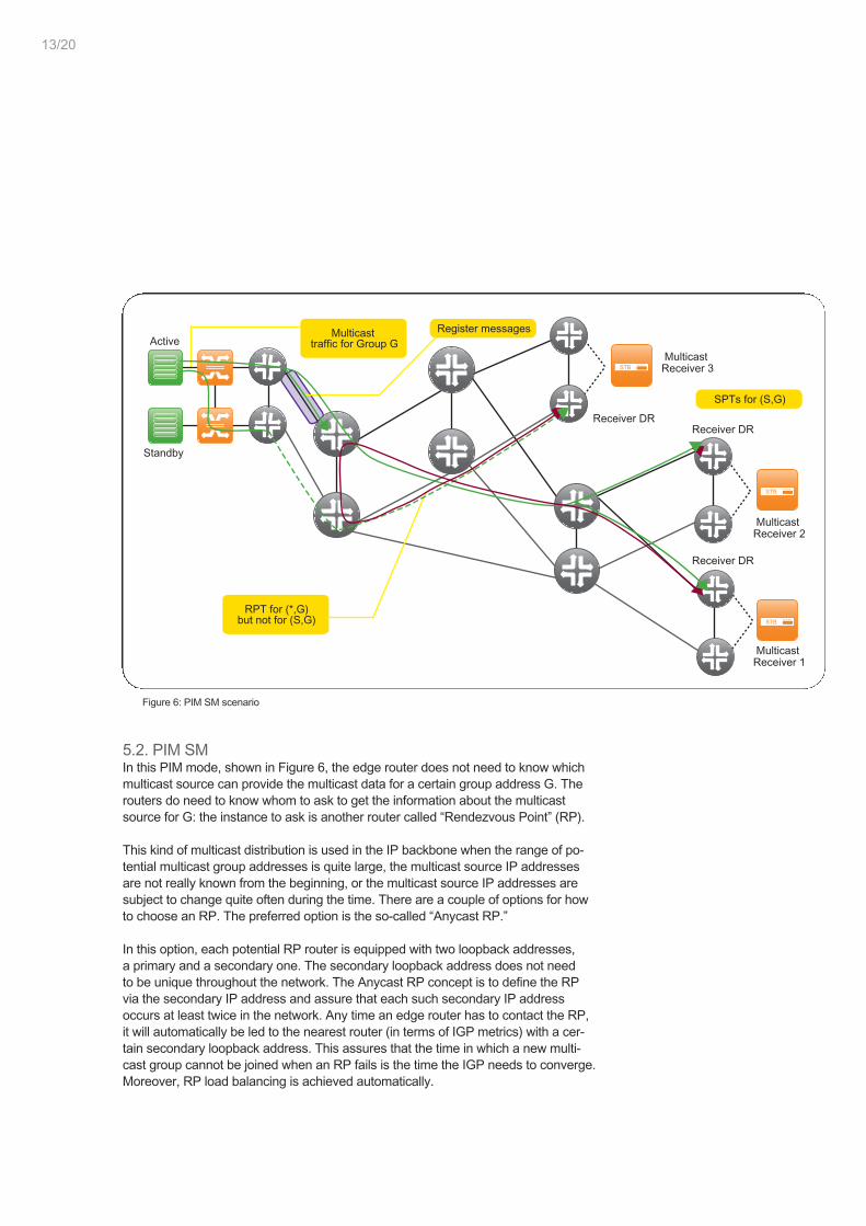
Figure 6: PIM SM scenario
5.2. PIM SMIn this PIM mode, shown in Figure 6, the edge router does not need to know whichmulticast source can provide the multicast data for a certain group address G. Therouters do need to know whom to ask to get the information about the multicastsource for G: the instance to ask is another router called “Rendezvous Point” (RP).
This kind of multicast distribution is used in the IP backbone when the range of po-tential multicast group addresses is quite large, the multicast source IP addressesare not really known from the beginning, or the multicast source IP addresses aresubject to change quite often during the time. There are a couple of options for howto choose an RP. The preferred option is the so-called “Anycast RP.”
In this option, each potential RP router is equipped with two loopback addresses,a primary and a secondary one. The secondary loopback address does not needto be unique throughout the network. The Anycast RP concept is to define the RPvia the secondary IP address and assure that each such secondary IP addressoccurs at least twice in the network. Any time an edge router has to contact the RP,it will automatically be led to the nearest router (in terms of IGP metrics) with a cer-tain secondary loopback address. This assures that the time in which a new multi-cast group cannot be joined when an RP fails is the time the IGP needs to converge.Moreover, RP load balancing is achieved automatically.
13/20
High-quality and resilient IPTV multicast architecture – Technical White Paper14/20
Standby
ActiveMulticast traffic for
Group G is mappedinto P2MP LSF
Receiver DR
Receiver DR
Receiver DR
MulticastReceiver 2
MulticastReceiver 3
MulticastReceiver 1
Multicast trafficfor Group G
P2MP LSP
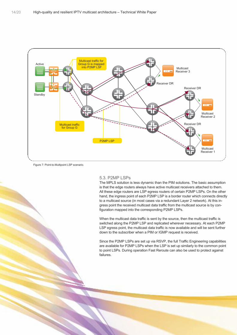
Figure 7: Point-to-Multipoint LSP scenario.
5.3. P2MP LSPsThe MPLS solution is less dynamic than the PIM solutions. The basic assumptionis that the edge routers always have active multicast receivers attached to them.All these edge routers are LSP egress routers of certain P2MP LSPs. On the otherhand, the ingress point of each P2MP LSP is a border router which connects directlyto a multicast source (in most cases via a redundant Layer 2 network). At this in-gress point the received multicast data traffic from the multicast source is by con-figuration mapped into the corresponding P2MP LSPs.
When the multicast data traffic is sent by the source, then the multicast traffic isswitched along the P2MP LSP and replicated wherever necessary. At each P2MPLSP egress point, the multicast data traffic is now available and will be sent furtherdown to the subscriber when a PIM or IGMP request is received.
Since the P2MP LSPs are set up via RSVP, the full Traffic Engineering capabilitiesare available for P2MP LSPs when the LSP is set up similarly to the common pointto point LSPs. During operation Fast Reroute can also be used to protect againstfailures.

High Quality and Resilient IPTV Multicast Architecture – Technical White Paper15/17
5.4. SummaryPIM SM is recommended in the IP backbone when the range of potential multicastgroup addresses is quite large, the multicast source IP addresses are not reallyknown from the beginning, or the multicast source IP addresses are subject tochange quite often during the time. Therefore the typical multicast applications touse PIM SM are voice, video conferencing (if realized by multicast at all), or gam-ing. The ResIP recommendation is to use PIM SSM or P2MP LSPs for IPTVservices.
Combining the multicast features with an intelligent implementation in the equip-ment (i.e. routers and switches), a subsecond failover time can be achieved forphysical and also Layer 3 failures. A number of failure types need to be looked at.This includes e.g. a link failure in the core, a failure of a router, or a failure of themulticast source itself. A concept has been developed to assure a subsecond fail-over time for all these failure cases (this includes the failure detection as well asthe failure recovery).
6. Conclusion
15/20
High-quality and resilient IPTV multicast architecture – Technical White Paper16/20
The Nokia Siemens Networks and Juniper Networks ResIP Certified IPTV solutionhas been certified in the ResIP Lab. It is based on mechanisms drawn from theNokia Siemens Networks SURPASS Home Entertainment solution, the NokiaSiemens Networks SURPASS Carrier Ethernet, the Juniper Networks M- andT-series routing platform, and the Juniper Networks E-series Broadband ServicesRouters. The solution reduces operational costs through a well-designed sub-scriber management using Zero Touch Provisioning.
User expectations of high-quality services delivered over a broadband network willbe no different from what is expected of today’s legacy video broadcast systems.Continuous service availability will be taken for granted, and QoS should not becompromised, even when a failure occurs in the network. Video services put strictdemands on packet loss and delay; to some extent, these requirements are evenhigher than for voice. Nokia Siemens Networks and Juniper Networks havedeveloped a QoS design that identifies various traffic types, and manages eachaccording to its specific requirements across multiple links and network elements.
The Nokia Siemens Networks and Juniper Networks ResIP Certified IPTV solutionalso addresses critical aspects of network security. The solution applies commonsecurity policies across the entire network to secure voice and video services fromnetwork-based attacks and to protect against DoS attacks.
SURPASS Integration Solutions offers tailor-made support for the effective andfast integration of new products and applications in today’s complex and hetero-geneous multi-vendor networks, and allows network operators to participate in theResIP outcomes.
Our approach is based on an in-depth understanding of your needs, priorities, andrequirements, thus enabling us to develop an optimized solution. We analyze yourbusiness requirements and customize products and applications to your specificneeds. Prior to implementing the solution, we perform comprehensive tests suchas performance and conformance testing, interoperability checks, and technicalverification in a reference system to ensure proven end-to-end functionality.
Integration projects carried out by Nokia Siemens Networks result in fasterrevenue generation, while keeping expenditure to a minimum by delivering theright quality, at the right cost, and at the right time, and should you wish to seehow our standard solution would meet your demands, we can carry out a trial onsite or at one of our Nokia Siemens Networks Integration Laboratories.
For more information about SURPASS Carrier-Grade IP Solutions and theResIP PoC Lab visit www.resip.net.
For more about Juniper Networks routers, visit www.juniper.net.
Engineering rules and designguidelines are available forservice providers who want totake advantage of the ResIPengineering excellence.
Nokia Siemens NetworksSURPASS Integration Solutionssupport customers for fast andriskless integration of new ser-vices on multi-vendor networks.
Learn more!
6. Conclusion
The solution-based expertise and experience Nokia Siemens Networks hasgained in worldwide installations of voice and packet networks has resulted in arange of unrivalled offerings. Nokia Siemens Networks is a strong and reliablepartner that offers a stable relationship for conducting successful business in thehighly competitive carrier market. Our experience and know-how can also bedemonstrated with regard to our customer base, strategic partners, and in theavailability of more than one hundred certified IP experts worldwide. This globalpresence and a strong service organization support carriers 24 hours a day,7 days a week.
Nokia Siemens Networks works together with preferred partner companies, all atthe leading edge in their segment, including Juniper Networks, with its leading IPproduct portfolio for BSR solutions, edge and core networks, and securitytechnologies.
Juniper Networks has been helping its customers build the largest, most reliable,and most profitable IP networks in the world for nearly ten years. This blend ofworld-class offerings and partnerships and our global presence and expertise offerthe best possible guarantee that Nokia Siemens Networks Next GenerationNetwork solutions are truly carrier-grade.
Nokia Siemens Networks and Juniper Networks have collaborated to develop anend-to-end IP architecture for next generation networks that supports voice, video,and data solutions as SURPASS Home Entertainment and SURPASSVoIP@Home.
This architecture enables service providers to offer an assured experiencebased on customer and application requirements. ResIP Certified Solutionsthat have already undergone stringent testing are available to service pro-viders for immediate deployment.
7. About Nokia SiemensNetworks
and Juniper NetworksNokia Siemens Networks is:
• A Juniper Networks Author-ized Education Centerto enable operators’ engi-neers;
• An official partner in theJuniper Networks Contentand Applications Allianceto develop revenue genera-ting solutions for operators;
• The first Juniper partner tohave achieved the statusof Juniper Networks Author-ized Global Support Pro-vider, which offers the fullrange of support servicesfrom installation to optimi-zation worldwide.
17/20

High-quality and resilient IPTV multicast architecture – Technical White Paper18/20
Nokia Siemens Networks and Juniper Networks are working together to solve thetoughest challenges service providers are currently facing. ResIP is designed tohelp service providers through these tough times of decreasing voice revenue anddeclining customer base. It includes a well-defined program to develop, test, andcertify all technology for the next generation architecture and solutions. The result-ing benefits to service providers is a fully tested and complete network architecturethat allow multiple certified solutions to be deployed for new revenue opportunities.
• Nokia Siemens Networks is one of the largest players in the global telecom-munications industry. Nokia Siemens Networks is the only provider in the marketthat offers its customers a full-range portfolio, from devices for end users to com-plex network infrastructures for enterprises and carriers, as well as related ser-vices. Nokia Siemens Networks Communications is the world’s innovation leaderin convergent technologies, products, and services for wireless, fixed, and enter-prise networks.
• Juniper Networks is the leader in enabling secure and assured communicationsover a single IP network. The company’s purpose-built, high-performance IPplatforms enable customers to support many different services and applicationsat scale. Service providers, enterprises, governments, and research and educa-tion institutions worldwide rely on Juniper Networks to deliver products for build-ing networks that are tailored to the specific needs of their users, services, andapplications. Juniper Networks’ portfolio of proven networking and security so-lutions supports the complex scale, security, and performance requirements ofthe world’s most demanding networks.

ATM Asynchronous Transfer ModeBSR Broadband Services RouterC-VLAN Customer VLANCPE Customer Premises EquipmentDHCP Dynamic Host Configuration ProtocolDR Designated RouterDSL Digital Subscriber LineDSLAM Digital Subscriber Line Access
MultiplexerEPG Electronic Program GuideERP Ethernet Ring ProtectionFEC Forward Error CorrectionFTTH Fiber to the HomeGOP Group of PicturesHDTV High-Definition TelevisionHSI High-Speed InternetIEEE Institute of Electrical and
Electronics EngineersIGMP Internet Group Management ProtocolIGP Interior Gateway ProtocolIP Internet ProtocolIPoE Internet Protocol over EthernetIPTV Internet Protocol TelevisionIS-IS Intermediate System to Intermediate
SystemL2C Layer 2 ControlLSP Label Switched PathMbit/s Megabit per SecondMPEG Motion Pictures Expert GroupMPLS Multiprotocol Label Switching
MPLS-TE MPLS Traffic EngineeringOAM Operation and MaintenanceOAM&P Operation and Maintenance &
ProvisioningPIM-SM Protocol Independent Multicast
Sparse ModePIM-SSM Protocol Independent Multicast
Source-Specific ModePoC Proof-of-ConceptPPP Point-to-Point ProtocolPPPoE PPP over EthernetP2MP Point-to-MultipointPVC Permanent Virtual CircuitQoS Quality of ServiceRAM Rate Adaptive ModeResIP Resilient IPRP Rendevouz PointRSTP Rapid Spanning Tree ProtocolRSVP Resource Reservation ProtocolS-VLAN Service VLANSDTV Standard-Definition TelevisionSPT Shortest Path FirstSTB Set-Top BoxSTP Spanning Tree ProtocolVLAN Virtual LAN
8. Abbreviations
19/20

www.nokiasiemensnetworks.com
Nokia Siemens Networks CorporationP.O. Box 102022 Nokia Siemens NetworksFinland
Visiting address:Karaportti 3, Espoo, Finland
Switchboard +358-71-400-4000 (Finland)Switchboard +49-89-515-901 (Germany)
The contents of this document are copyright © 2008 Nokia Siemens Networks.All rights reserved. A license is hereby granted to download and print a copy ofthis document for personal use only. No other license to any other intellectual prop-erty rights is granted herein. Unless expressly permitted herein, reproduction,transfer, distribution, or storage of part, or all, of the contents in any form withoutthe prior written permission of Nokia Siemens Networks is prohibited. The contentof this document is provided “AS IS”, without warranties of any kind with regards toits accuracy or reliability, and specifically excluding all implied warranties, for exam-ple of merchantability, fitness for purpose, title, and non-infringement. In no event shallNokia Siemens Networks be liable for any special, indirect, or consequential dam-ages, or any damages whatsoever resulting from loss of use, data, or profits, arisingout of, or in connection with, the use of the document. Nokia Siemens Networksreserves the right to revise the document or withdraw it at any time without priornotice. Nokia Siemens Networks and the Wave logo are registered trademarks ofNokia Siemens Networks. Nokia Siemens Networks product names are eithertrademarks or registered trademarks of Nokia Siemens Networks. Other productand company names mentioned herein may be trademarks or trade names of theirrespective owners.
Order No. C401-00114-WP-200803-1-EN