High Pressure Homogenizer - Miller...
11
www.avestin.com AVESTIN, Inc. 2450 Don Reid Drive, Ottawa, ON, Canada, K1H 1E1, e-mail:[email protected], website:www.avestin.com Tel: -613-736-0019, Fax: -613-736-8086, US & CDN customers call toll free: 1-888-AVESTIN (283-7846) No voice mail: a qualified person will answer your call in the language of your choice: English, Deutsch, Français 1 1 Operating Instructions for the EmulsiFlex ® -C3 High Pressure Homogenizer EmulsiFlex Principle of Operation: A high pressure pump (C) pushes the product through an adjustable homogenizing valve (D). The product can also be passed through a membrane (E). It can be collected (G) or recycled to the reservoir (A) via tubing/pipes or heat exchanger (F). EmulsiFlex equipment can be delivered as: 1-High pressure homogenizer (A,C,D,F,G) 2-High pressure filter/extruder (A,C,E,G) 3-Homogenizer/filter/extruder combination (A,C,D,E,G) 4-Two-phase homogenizer/filter/extruder with precision metering pumps, or as shown to the left (A,B,C,D,E,F,G). B JACKETED CONTAINER D A G E F C
Transcript of High Pressure Homogenizer - Miller...
www.avestin.com AVESTIN, Inc. 2450 Don Reid Drive, Ottawa, ON, Canada, K1H 1E1, e-mail:[email protected], website:www.avestin.com Tel: -613-736-0019, Fax: -613-736-8086, US & CDN customers call toll free: 1-888-AVESTIN (283-7846) No voice mail: a qualified person will answer your call in the language of your choice: English, Deutsch, Français
1 1
Operating Instructions for the EmulsiFlex®-C3
High Pressure Homogenizer
EmulsiFlex Principle of Operation: A high pressure pump (C) pushes the product through an adjustable homogenizing valve (D). The product can also be passed through a membrane (E). It can be collected (G) or recycled to the reservoir (A) via tubing/pipes or heat exchanger (F). EmulsiFlex equipment can be delivered as: 1-High pressure homogenizer (A,C,D,F,G) 2-High pressure filter/extruder (A,C,E,G) 3-Homogenizer/filter/extruder combination (A,C,D,E,G) 4-Two-phase homogenizer/filter/extruder with precision metering pumps, or as shown to the left (A,B,C,D,E,F,G).
B
JACKETEDCONTAINER
D
AG
E
F
C
www.avestin.com
2
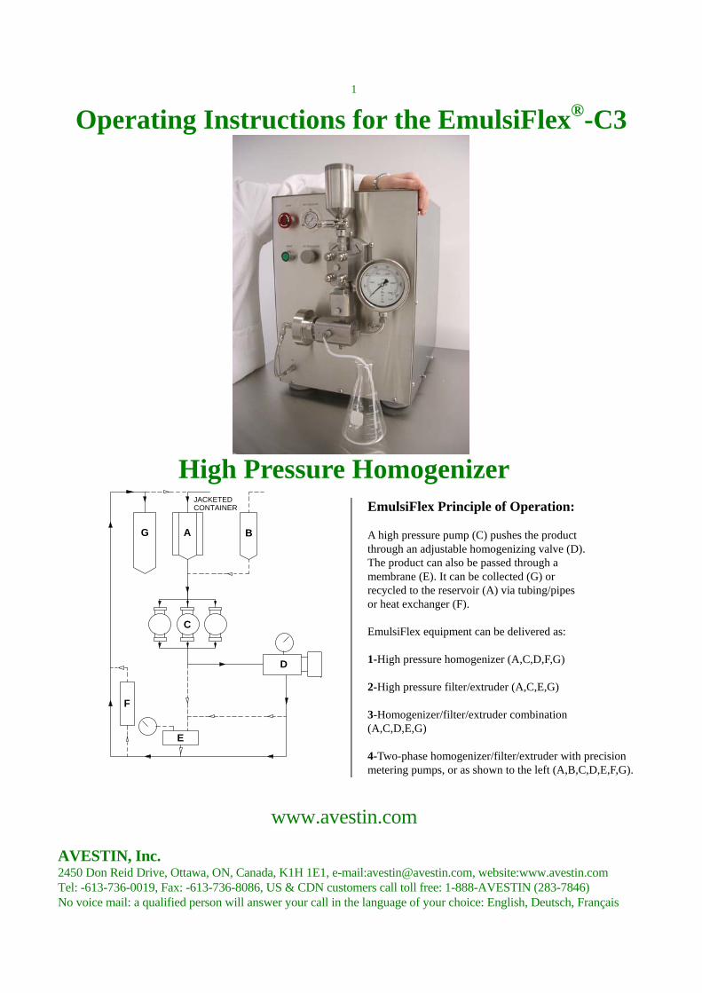
Figure 1: EmulsiFlex-C3 C3 Part List: 1 red stop button 2 green start button 3 air/gas pressure gauge 4 air/gas pressure regulator 5 sample cylinder cap 6 stainless steel sample cylinder 7 inlet sanitary fitting 8 inlet check valve
9 pump body 10 outlet check valve 11 homogenizing valve 12 pneumatic control cylinder 13 homogenizing pressure gauge 14 gauge nipple 15 pneumatic control air supply hose 16 glass sample cylinder

www.avestin.com
3
1 WARNINGS and General Information: 1.1 Incorrect operation may lead to discharge of fluids under pressure. Users must wear eye protection at all times. Gloves and protective clothing must be worn and machine must be operated in a contained area when working with pathogenic, toxic, or corrosive materials. All necessary precautions must be taken to ensure safe operation. 1.2 Do not run the machine dry for more than a few cycles. If the parts are not lubricated by a liquid, the plungers can seize in the pumps. This will significantly reduce the lifetime of the seals in the pumps. 1.3 Only run clean fluids through the machine. Contaminating particulate matter can block the check valves and prevent the machine from operating properly. 1.4 Your machine may have minor physical differences from the picture on the front of this manual. These differences may be due to modifications and improvements made to the equipment over time. Any differences do not alter any of the functions described below. 1.5 The regulator (Figure1, 4) is not a high pressure regulator; the incoming air/gas connection (on the rear of the EmulsiFlex) should not be attached to incoming gas with a pressure higher than 125psi/0.9MPa. This has to be taken into consideration when using bottled gas which can have a pressure of 3000psi/20.7MPa or more. 1.6 Use cold tap water to learn how to operate the instrument. Experiment with various pressures. The minimum sample volume is 10mL and the flow rate is 3L/hr and is independent of the homogenizing pressure selected. Do not attempt to run toxic, corrosive, or small sample volumes (less than 20mL) until you are familiar with the machine. 1.7 The EmulsiFlex-C3 homogenizer utilizes an electric motor-driven, high pressure, plunger pump developed by AVESTIN. There are no "O"-rings in the entire path of the product. The only plastic seal in the pump body is the UHMWPE (Ultra High Molecular Weight Polyethylene) plunger seal. There is a PTFE (Teflon) seal for the homogenizing valve stem. 1.8 Do not use excessive force when tightening any nuts on this instrument. Only tighten enough to prevent leakage. Contact AVESTIN, or their agent, directly if you have questions; please have your serial number ready.
1.9 If your EmulsiFlex-C3 was shipped in a wooden crate, please retain it. This container should be used if you need to return the instrument to AVESTIN for updating or servicing (see Section 12). 1.10 Do not attempt to disassemble the inside of the homogenizing valve (Figure 1, 11) without first consulting with AVESTIN or their agent. Please have the serial number of your instrument available. 1.11 Do not pressurize the pneumatic control cylinder (Figure 1, 12) before pumping fluid through the EmulsiFlex-C3. 1.12 Avoid scratching any sealing or internal surfaces. Since there are no "O"-ring seals in the pump body and homogenizing valve, parts must be precision machined and hardened. This makes it possible to disassemble and reassemble the check valves and homogenizing valve without need for any spare gaskets. This is a unique and unmatched feature of EmulsiFlex homogenizers. 1.13 The pump of the EmulsiFlex-C3 cannot be stalled. As the homogenizing valve is closed and the pressure increased, the electric motor draws more current to deal with the additional load on the system. There is a current limiting device on the EmulsiFlex-C3 that will shut down the system should dangerous current levels occur. 1.14 Do not run explosive material through the EmulsiFlex-C3. Specialized equipment is available for such conditions. Contact AVESTIN, or their agent, for further details. 1.15 Use factory supplied spare parts only. Parts from other sources, particularly high pressure parts, may result in injury and damage and will void the warranty. 1.16 Discontinue the use of the EmulsiFlex-C3 immediately should excess vibration occur. Call AVESTIN, or their agent, for information. 1.17 Should the EmulsiFlex-C3 stop during a process run for unknown reasons, consult with AVESTIN, or their agent, immediately. Help is available to diagnose the problem. 1.18 Do not run the EmulsiFlex-C3 without first reading the Operating Instructions (Section 3). Injury to personnel or machine damage could result from incorrect machine operation.
www.avestin.com
4
2 Requirements for operation 2.1 Electrical: The EmulsiFlex-C3 requires a single-phase electrical connection to power its standard 1.0hp/0.75kW motor. The equipment uses 230V, but is supplied with a transformer for use with 110V sources. Connection is made via the power cord at the back of the control box. The EmulsiFlex-C3 is equipped with current limiting devices to shut down the system should dangerous current levels occur. Do not tamper with these devices/settings. The optional peak reset meter (see Section 7) requires either 115V or 230V (single-phase), at either 50Hz or 60Hz. 2.2 Compressed Air/gas: Compressed air or bottled gas is required to power the pneumatic control cylinder (Figure 1, 12) that controls the homogenizing pressure. A maximum pressure of 125psi/0.9MPa is permitted. Compressed air from a compressor is suggested, but high pressure cylinders of any inert gas (air, Nitrogen, etc.) may be used. Make sure correct regulators are fitted to any high pressure gas cylinders. 2.3 Cooling Fluid: If a heat exchanger is used there are two ways to supply the cooling medium: A- connect the heat exchanger tubing to a cold water tap. B- use a small pump (e.g. peristaltic pump) to supply the heat exchanger with cooling medium such as ice water or brine solution from a chiller.
3 Operating instructions 3.1 Before starting: 3.1.1 Make certain that the red, mushroom STOP button (Figure 2, 1) is depressed and locked in the off position BEFORE connecting power to the instrument. 3.1.2 Ensure the single-phase power supply is 230V as specified on the EmulsiFlex-C3’s outer casing and is safely connected. If you have an 110V power source, the system must be run using a step-up autotransformer. 3.1.3 Connect the INCOMING AIR/GAS hose on the air manifold to an air compressor or gas cylinder. Using the air manifold, air can be supplied to both the air inlet on the back of the machine and to the sample cylinder if pressurization is required. OUTLET 1 and OUTLET 2 supply the same pressure and can be used for either purpose.
3.1.4 Ensure that the EmulsiFlex-C3 is on a flat, level surface for all running. 3.1.5 Make sure all high pressure fittings are snug. Do not over-tighten! If a fitting is loose, product will leak from the fitting once the feed fluid is pressurized, or when the homogenizer is started. 3.1.6 Connect the inlet check valve (Figure 1, 8) to either the stainless steel or glass sample cylinder using the sanitary fittings provided. 3.1.7 Make certain the outlet of the homogenizing valve (Figure 1, 11), or heat exchanger, is plumbed so that NO BLOCKAGE can occur. A blockage can lead to a rapid rise in pressure in the outlet tube/heat exchanger and a rupture can occur.
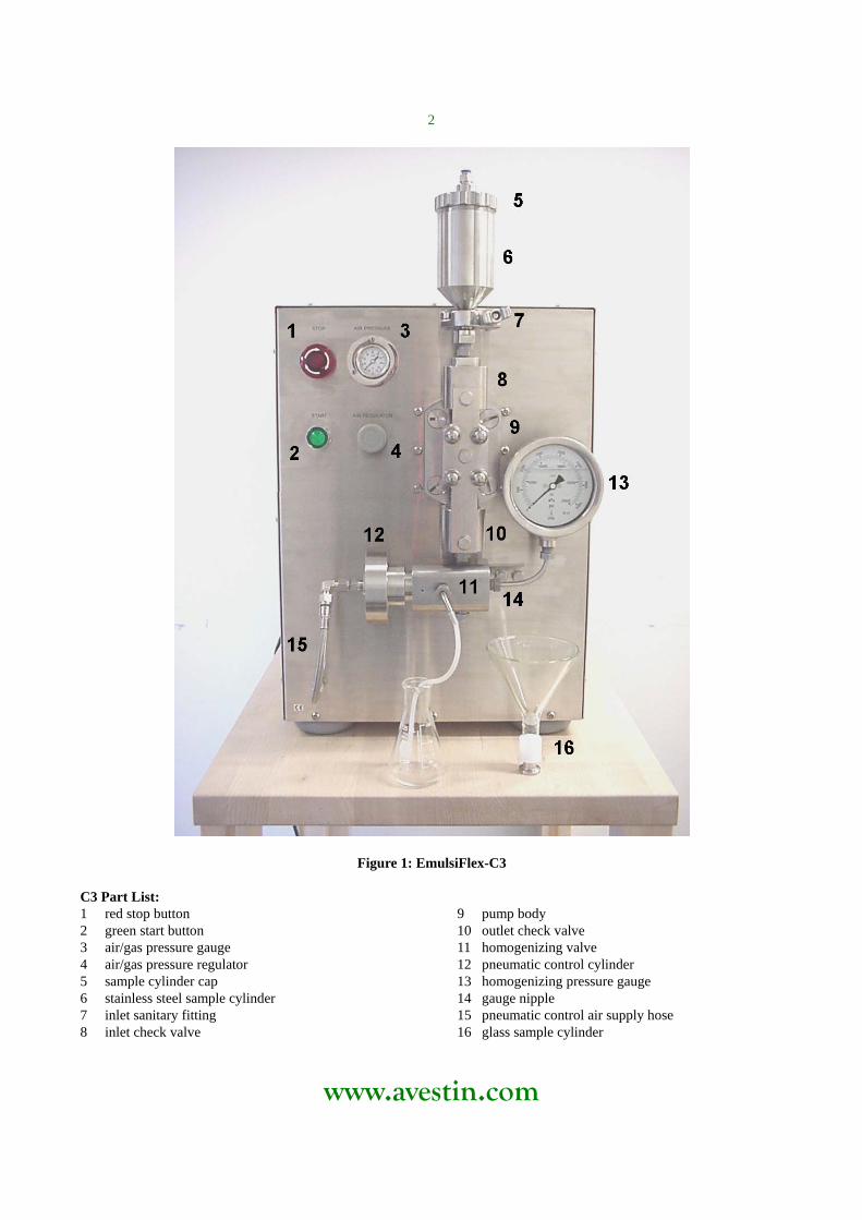
Figure 2: Close up view of the standard controls on the EmulsiFlex-C3 control box. 3.2 Starting and Running: 3.2.1 Switch on the main power supply located on the back of the EmulsiFlex-C3. 3.2.2 Start the flow of cooling fluid through the exit heat exchanger, if fitted. 3.2.3 Twist the red, STOP button (Figure 2, 1) clock-wise to disengage the stop lock. It should ‘pop’ out. 3.2.4 Press the green, START button (Figure 2, 2). The EmulsiFlex-C3 will start pumping and the green START button should illuminate.

www.avestin.com
5
3.2.5 Increase the homogenizing pressure, monitored by the gauge (Figure 1, 13) or by the peak reset meter (see Section 7), by turning the regulator (Figure 2, 4) CLOCK-WISE. 3.3 Stopping: 3.3.1 Press the red, mushroom STOP button (Figure 2, 1) until it LOCKS into place. This button must be twisted clock-wise before starting the EmulsiFlex-C3 again. 3.3.2 In an emergency, IMMEDIATELY depress the red, mushroom STOP button (Figure 2, 1). Do not take the time to dial the homogenizing pressure down to 0psi/0MPa. Reduce pressure in the pneumatic control cylinder (Figure 1, 12) using the regulator (Figure 2, 4) after stopping. 3.3.3 Once the EmulsiFlex-C3 has been stopped shut off the main power and the air/gas supply to the EmulsiFlex if it is to be idle for a prolonged period. It is suggested that the EmulsiFlex-C3 be cleaned before sitting for long periods of time. See Section 8. 4. Operation of the Filter/Extruder 4.1 Assemble the filter/extruder system as shown in Figure 3. Use the brown stainless steel screws provided to secure the filter/extruder unit. Only the provided brown screws should be used. The brown colour is the result of the hardening process giving them the extreme strength required. Tighten screws with the slot key provided. These screws have to be tightened firmly to make sure they do not loosen and open during processing.
Figure 3: Filter/extruder assembly.
4.2 Mount the filter/extruder as shown in Figure 4 using the wrench provided. Do not over-tighten the gland nuts. 4.3 The pressure of the filtration/extrusion process can be monitored by a gauge (Figure 4, 18). This gauge is supplied with all filter/extruder units. It is also possible to use an optional peak-reset meter and pressure transducer to measure the pressure of this process. The maximum pressure allowed is approximately 6500psi/ 45MPa. Be careful not to exceed this pressure. Viscous or other unsuitable products will not extrude and the pressure will exceed the allowable level. Product will be released through the safety venting groves in the extruder.
Figure 4: Filter/extruder assembly (17) and pressure gauge (18) mounted on an EmulsiFlex-C3. 4.4 The homogenizing valve should remain fully open during the filtration/extrusion process. The homogenizing pressure gauge will display the same pressure as the extrusion gauge. If the sample requires homogenization and filtration/extrusion, these operations should be performed in separate passes. 5 Cooling the Sample 5.1 Processing samples repeatedly and/or at high pressures causes the product to heat up. For temperature sensitive products, a heat exchanger (Figure 5, 19) is available from AVESTIN. The heat exchanger can be installed without any modification to the EmulsiFlex as shown in Figure 5. Heat exchangers supplied with the EmulsiFlex-C3 are sanitary in design and are of the shell and tube variety.
www.avestin.com
6
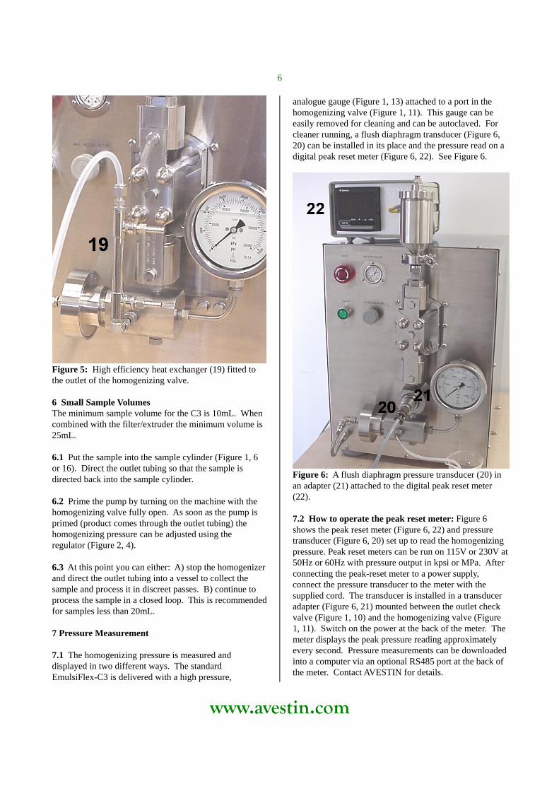
Figure 5: High efficiency heat exchanger (19) fitted to the outlet of the homogenizing valve. 6 Small Sample Volumes The minimum sample volume for the C3 is 10mL. When combined with the filter/extruder the minimum volume is 25mL. 6.1 Put the sample into the sample cylinder (Figure 1, 6 or 16). Direct the outlet tubing so that the sample is directed back into the sample cylinder. 6.2 Prime the pump by turning on the machine with the homogenizing valve fully open. As soon as the pump is primed (product comes through the outlet tubing) the homogenizing pressure can be adjusted using the regulator (Figure 2, 4). 6.3 At this point you can either: A) stop the homogenizer and direct the outlet tubing into a vessel to collect the sample and process it in discreet passes. B) continue to process the sample in a closed loop. This is recommended for samples less than 20mL. 7 Pressure Measurement 7.1 The homogenizing pressure is measured and displayed in two different ways. The standard EmulsiFlex-C3 is delivered with a high pressure,
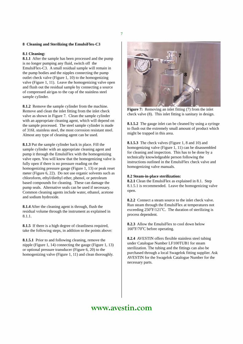
analogue gauge (Figure 1, 13) attached to a port in the homogenizing valve (Figure 1, 11). This gauge can be easily removed for cleaning and can be autoclaved. For cleaner running, a flush diaphragm transducer (Figure 6, 20) can be installed in its place and the pressure read on a digital peak reset meter (Figure 6, 22). See Figure 6.
Figure 6: A flush diaphragm pressure transducer (20) in an adapter (21) attached to the digital peak reset meter (22). 7.2 How to operate the peak reset meter: Figure 6 shows the peak reset meter (Figure 6, 22) and pressure transducer (Figure 6, 20) set up to read the homogenizing pressure. Peak reset meters can be run on 115V or 230V at 50Hz or 60Hz with pressure output in kpsi or MPa. After connecting the peak-reset meter to a power supply, connect the pressure transducer to the meter with the supplied cord. The transducer is installed in a transducer adapter (Figure 6, 21) mounted between the outlet check valve (Figure 1, 10) and the homogenizing valve (Figure 1, 11). Switch on the power at the back of the meter. The meter displays the peak pressure reading approximately every second. Pressure measurements can be downloaded into a computer via an optional RS485 port at the back of the meter. Contact AVESTIN for details.
www.avestin.com
7
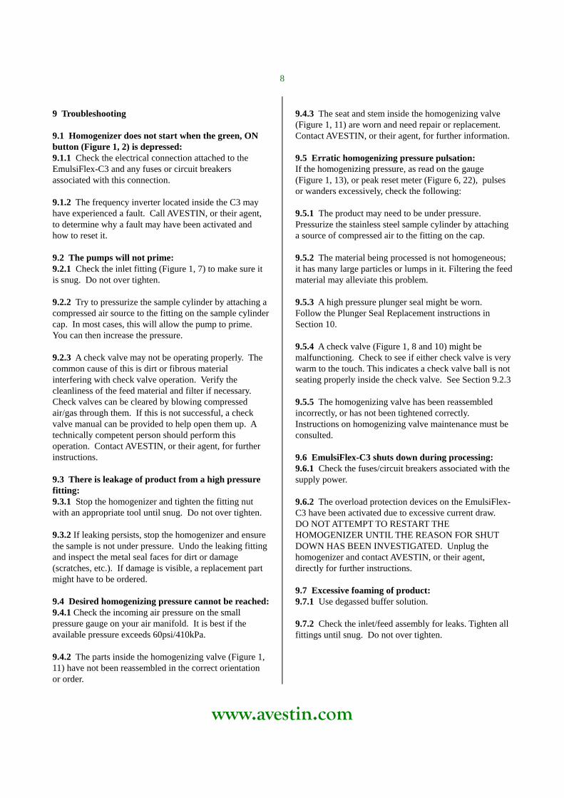
8 Cleaning and Sterilizing the EmulsiFlex-C3 8.1 Cleaning: 8.1.1 After the sample has been processed and the pump is no longer pumping any fluid, switch off the EmulsiFlex-C3. A small residual sample will remain in the pump bodies and the nipples connecting the pump outlet check valve (Figure 1, 10) to the homogenizing valve (Figure 1, 11). Leave the homogenizing valve open and flush out the residual sample by connecting a source of compressed air/gas to the cap of the stainless steel sample cylinder. 8.1.2 Remove the sample cylinder from the machine. Remove and clean the inlet fitting from the inlet check valve as shown in Figure 7. Clean the sample cylinder with an appropriate cleaning agent, which will depend on the sample processed. The steel sample cylinder is made of 316L stainless steel, the most corrosion resistant steel. Almost any type of cleaning agent can be used. 8.1.3 Put the sample cylinder back in place. Fill the sample cylinder with an appropriate cleaning agent and pump it through the EmulsiFlex with the homogenizing valve open. You will know that the homogenizing valve is fully open if there is no pressure reading on the homogenizing pressure gauge (Figure 1, 13) or peak reset meter (Figure 6, 22). Do not use organic solvents such as chloroform, ethyl/diethyl ether, phenol, or petroleum based compounds for cleaning. These can damage the pump seals. Alternative seals can be used if necessary. Common cleaning agents include water, ethanol, acetone and sodium hydroxide. 8.1.4 After the cleaning agent is through, flush the residual volume through the instrument as explained in 8.1.1. 8.1.5 If there is a high degree of cleanliness required, take the following steps, in addition to the points above: 8.1.5.1 Prior to and following cleaning, remove the nipple (Figure 1, 14) connecting the gauge (Figure 1, 13) or optional pressure transducer (Figure 6, 20) to the homogenizing valve (Figure 1, 11) and clean thoroughly.
Figure 7: Removing an inlet fitting (7) from the inlet check valve (8). This inlet fitting is sanitary in design. 8.1.5.2 The gauge inlet can be cleaned by using a syringe to flush out the extremely small amount of product which might be trapped in this area. 8.1.5.3 The check valves (Figure 1, 8 and 10) and homogenizing valve (Figure 1, 11) can be disassembled for cleaning and inspection. This has to be done by a technically knowledgeable person following the instructions outlined in the EmulsiFlex check valve and homogenizing valve manuals. 8.2 Steam-in-place sterilization: 8.2.1 Clean the EmulsiFlex as explained in 8.1. Step 8.1.5.1 is recommended. Leave the homogenizing valve open. 8.2.2 Connect a steam source to the inlet check valve. Run steam through the EmulsiFlex at temperatures not exceeding 250oF/121oC. The duration of sterilizing is process dependent. 8.2.3 Allow the EmulsiFlex to cool down below 160oF/70oC before operating. 8.2.4 AVESTIN offers flexible stainless steel tubing under Catalogue Number LF100TUB1 for steam sterilization. The tubing and the fittings can also be purchased through a local Swagelok fitting supplier. Ask AVESTIN for the Swagelok Catalogue Number for the necessary parts.
www.avestin.com
8
9 Troubleshooting 9.1 Homogenizer does not start when the green, ON button (Figure 1, 2) is depressed: 9.1.1 Check the electrical connection attached to the EmulsiFlex-C3 and any fuses or circuit breakers associated with this connection. 9.1.2 The frequency inverter located inside the C3 may have experienced a fault. Call AVESTIN, or their agent, to determine why a fault may have been activated and how to reset it. 9.2 The pumps will not prime: 9.2.1 Check the inlet fitting (Figure 1, 7) to make sure it is snug. Do not over tighten. 9.2.2 Try to pressurize the sample cylinder by attaching a compressed air source to the fitting on the sample cylinder cap. In most cases, this will allow the pump to prime. You can then increase the pressure. 9.2.3 A check valve may not be operating properly. The common cause of this is dirt or fibrous material interfering with check valve operation. Verify the cleanliness of the feed material and filter if necessary. Check valves can be cleared by blowing compressed air/gas through them. If this is not successful, a check valve manual can be provided to help open them up. A technically competent person should perform this operation. Contact AVESTIN, or their agent, for further instructions. 9.3 There is leakage of product from a high pressure fitting: 9.3.1 Stop the homogenizer and tighten the fitting nut with an appropriate tool until snug. Do not over tighten. 9.3.2 If leaking persists, stop the homogenizer and ensure the sample is not under pressure. Undo the leaking fitting and inspect the metal seal faces for dirt or damage (scratches, etc.). If damage is visible, a replacement part might have to be ordered. 9.4 Desired homogenizing pressure cannot be reached: 9.4.1 Check the incoming air pressure on the small pressure gauge on your air manifold. It is best if the available pressure exceeds 60psi/410kPa. 9.4.2 The parts inside the homogenizing valve (Figure 1, 11) have not been reassembled in the correct orientation or order.
9.4.3 The seat and stem inside the homogenizing valve (Figure 1, 11) are worn and need repair or replacement. Contact AVESTIN, or their agent, for further information. 9.5 Erratic homogenizing pressure pulsation: If the homogenizing pressure, as read on the gauge (Figure 1, 13), or peak reset meter (Figure 6, 22), pulses or wanders excessively, check the following: 9.5.1 The product may need to be under pressure. Pressurize the stainless steel sample cylinder by attaching a source of compressed air to the fitting on the cap. 9.5.2 The material being processed is not homogeneous; it has many large particles or lumps in it. Filtering the feed material may alleviate this problem. 9.5.3 A high pressure plunger seal might be worn. Follow the Plunger Seal Replacement instructions in Section 10. 9.5.4 A check valve (Figure 1, 8 and 10) might be malfunctioning. Check to see if either check valve is very warm to the touch. This indicates a check valve ball is not seating properly inside the check valve. See Section 9.2.3 9.5.5 The homogenizing valve has been reassembled incorrectly, or has not been tightened correctly. Instructions on homogenizing valve maintenance must be consulted. 9.6 EmulsiFlex-C3 shuts down during processing: 9.6.1 Check the fuses/circuit breakers associated with the supply power. 9.6.2 The overload protection devices on the EmulsiFlex-C3 have been activated due to excessive current draw. DO NOT ATTEMPT TO RESTART THE HOMOGENIZER UNTIL THE REASON FOR SHUT DOWN HAS BEEN INVESTIGATED. Unplug the homogenizer and contact AVESTIN, or their agent, directly for further instructions. 9.7 Excessive foaming of product: 9.7.1 Use degassed buffer solution. 9.7.2 Check the inlet/feed assembly for leaks. Tighten all fittings until snug. Do not over tighten.

www.avestin.com
9
10 Plunger Seal Replacement 10.1 Seal Removal: 10.1.1 The pump head must be removed from the EmulsiFlex-C3 to perform this operation. Disconnect the sample cylinder from the sanitary fitting of the inlet check valve. Remove high pressure gauge (Figure 1, 13) or transducer cable (Figure 6, 20), if fitted. Remove the braided, steel air hose (Figure 1, 15) from the bottom of the pneumatic control cylinder. Undo and remove the four large cap nuts holding the check valve support plate to the EmulsiFlex. 10.1.2 Remove the two bolts that connect the homogenizing valve support bracket to the front of the EmulsiFlex. 10.1.3 Disconnect the homogenizing valve (Figure 1, 11) from the outlet check valve (Figure 1, 10) by undoing the high pressure fitting between them. 10.1.4 The entire pump head assembly can now be pulled off of the guide rods slowly and squarely. It is strongly suggested that two people perform this step. 10.1.5 Once the pump head has been removed, stand assembly on pump end on a flat surface.
Figure 8: EmulsiFlex-C3 plunger seal removal. 10.1.6 Remove the pump body cap (Figure 8, 5) by turning counter-clockwise. 10.1.7 The steel, seal back-up support (Figure 8, 4) can
now be removed. A small puff of compressed air down the center of the seal back up support will pop it up, out of the pump body. 10.1.8 The black, seal back-up (Figure 8, 3) can now be seen in the centre of the pump body cavity. It can be removed easily and is not tight. Retain this part if seals are just being inspected/cleaned. Discard if seals are being replaced. 10.1.9 The white, high pressure plunger seal (Figure 8, 2) is now visible in the centre of the pump body cavity. It fits tightly in the pump body. Remove with care and retain if the seals are just being inspected/cleaned. Discard if seals are being replaced. 10.1.10 If the seal set is just being inspected/cleaned, look at the white, high pressure plunger seal (Figure 8, 2) and black seal back-up (Figure 8, 3) for signs of damage or wear. If any cracks or signs of extrusion are visible, replace both seal parts (Figure 8, 2 & 3). Replacement seals are purchased under catalogue number C5PLSEAL1. 10.2 Plunger Seal Insertion: 10.2.1 It is recommended that the plunger seal insertion tool (Figure 9, 6 & 7) is used for this operation. It can be purchased under Catalogue Number C55SLTOL1. 10.2.2 Insert the disk shaped part of the insertion tool (Figure 9, 6) as shown into the top of the pump body. Make sure it is inserted all the way, and is flat.
Figure 9: EmulsiFlex-C3 plunger seal insertion.
1
65
7

www.avestin.com
10
10.2.3 Position the white, high pressure seal (Figure 8, 5) with the spring down, in the hole in the centre of the insertion tool (Figure 9, 6). Its orientation can be corrected with the tip of a pen or pencil once dropped in the hole, if necessary. 10.2.4 Press on the back of the high pressure seal with the insertion plunger (Figure 9, 7) as shown. This compresses the seal slightly as it enters the pump body. Once the seal bottoms out, it is seated correctly. 10.2.5 Remove the disk shaped portion of the seal insertion tool (Figure 9, 6) and inspect the seal. It should be sitting flat in the bottom of the socket in the pump body (Figure 9, 1). The spring should not be visible as it is face down. 10.2.6 Take the black, seal back-up (Figure 8, 3) and position it on top of the white, high pressure seal. Push lightly with your finger; it should slide into the socket in the pump body on top of the high pressure seal. 10.2.7 Replace the steel, seal back-up support (Figure 8, 4). 10.2.8 Replace the pump body cap (Figure 8, 5) by turning it clockwise onto the pump body. 10.2.9 Reposition the pump head assembly on the guide rods protruding from the front of the EmulsiFlex-C3. Slide the assembly onto the plunger slowly and squarely until the assembly almost touches the stainless steel front panel. Tighten the cap nuts such that the pump head is evenly moved into place. Tighten until very snug. Replace sample cylinder, and stainless steel pneumatic control air line.
11 Specific Applications The EmulsiFlex-C3 is capable of handling an extremely wide range of applications. Only a few of the most common applications are outlined below. In almost every case it will be necessary for the individual operator to work out details specific to their own applications. 11.1 Cell rupture: One pass through the homogenizer at 15000-17000psi/103-117MPa has been shown to rupture almost all of the cells in a batch of E. coli. More resistant cells, including Piccia, Saccharomyces and Mycobacterium, can be ruptured at higher pressures (>22000psi/152MPa) with multiple passes. See Figure 10.
Figure 10: Cells ruptured by an EmulsiFlex high pressure homogenizer. Undisrupted Schizosaccharomyces pombe (yeast) cells (left) and cell fragments after processing at 28000psi/193MPa. 11.2 Liposomes: Exact parameters will depend on the components and their concentration in each formulation. In general, 4 passes through the homogenizer at 15000psi/103MPa are sufficient to form a homogeneous population of unilamellar liposomes. See Figure 11.
Figure 11: Some examples of Liposomes. 11.3 Emulsions: Exact parameters will depend on the emulsion components and their concentrations. In general, 1-4 passes through the homogenizer at 10000-20000psi/69-138MPa are sufficient to form a homogeneous emulsion. If this does not work for your sample, try altering the number of passes through the EmulsiFlex or different homogenizing pressures (either higher or lower).

www.avestin.com AVESTIN, Inc. 2450 Don Reid Drive, Ottawa, ON, Canada, K1H 1E1, e-mail:[email protected], website:www.avestin.com Tel: -613-736-0019, Fax: -613-736-8086, US & CDN customers call toll free: 1-888-AVESTIN (283-7846) No voice mail: a qualified person will answer your call in the language of your choice: English, Deutsch, Français
11 11
11.4 Dispersions: The size of dispersion particles can be dramatically reduced by processing through the EmulsiFlex-C3 through its entire pressure range. If the starting material is not stable (particles separate out quickly), it is often useful to run a first pass at low pressure (approx. 5000psi/35MPa) to break down the largest particles. Pressure can be increased incrementally from this point. See Figure 12.
Figure 12: Unprocessed dispersion (10-100microns, left) and processed, uniform dispersion (1micron, right) using an EmulsiFlex homogenizer at 25000psi/173MPa. 12 Scaling Up, Scaling Down 12.1 Scaling Up: AVESTIN manufactures standard and custom made EmulsiFlex homogenizers up to 1000L/h continuous flow at pressures up to 30000psi/207MPa. Contact AVESTIN, or their agent, directly concerning larger homogenizing equipment. 12.2 Scaling Down: There are two standard EmulsiFlex units smaller than the EmulsiFlex-C3: the EmulsiFlex-C5 and the EmulsiFlex-B3. The LiposoFast line of extruders is available for the preparation liposomes/emulsions in small volumes from 0.1 to 100mL. Extrusion is through polycarbonate membranes of defined pore sizes. Please contact AVESTIN, or their agent, for more information on the LiposoFast line of extruders. 12.2.1 EmulsiFlex-C5: The EmulsiFlex-C5 is capable of processing at rates between 1 and 5L/hr depending on the homogenizing pressure (up to 30000psi/207MPa). It is powered by compressed air/gas alone. The entire unit can be autoclaved and immersed in a temperature controlled water bath.
12.2.3 EmulsiFlex-B3: A batch homogenizer for volumes from 1mL to 3.5mL. This air-powered machine is capable of pressures up to 30000psi/207MPa (not shown in Figure 13).
Figure 13: Standard EmulsiFlex homogenizers. Custom models are available upon request. Call AVESTIN for details. 13 Shipping All EmulsiFlex homogenizers are shipped in high quality, wood crates. KEEP THIS CRATE as it is the best way to store/transport your homogenizer.
Figure 14: All equipment is shipped in high quality wood crates. Please retain crate for future use.


![Instuderingsfr%C3%A5gor - Marknadsf%C3%B6ring[1]](https://static.fdocuments.in/doc/165x107/552034774a79595e718b4682/instuderingsfrc3a5gor-marknadsfc3b6ring1.jpg)