![Topic 5 Revision [142 marks]...A. The power dissipated is greatest in resistor X. B. The power dissipated is greatest in resistor Y. C. The power dissipated is greatest in resistor](https://static.fdocuments.in/doc/165x107/612424069d30ae5643133d79/topic-5-revision-142-marks-a-the-power-dissipated-is-greatest-in-resistor.jpg)
High Pressure control - Schneider · PDF fileHigh Pressure control ... cooler and fluid,...
14
Make the most of your energy Energy savings in commercial refrigeration equipment : High Pressure control November 2010/White paper by Christophe Borlein AFF and IIF-IIR member
Transcript of High Pressure control - Schneider · PDF fileHigh Pressure control ... cooler and fluid,...
Make the most of your energy
Energy savings in commercial refrigeration equipment :
High Pressure control November 2010/White paper
by Christophe Borlein
AFF and IIF-IIR member

Summary
Foreword I
Introduction II
Commercial refrigeration system 1
High Pressure 2
HP control modes 3
Concretely on the field 5
Application on storage system 6
Generic application 7
Conclusion 8
Foreword
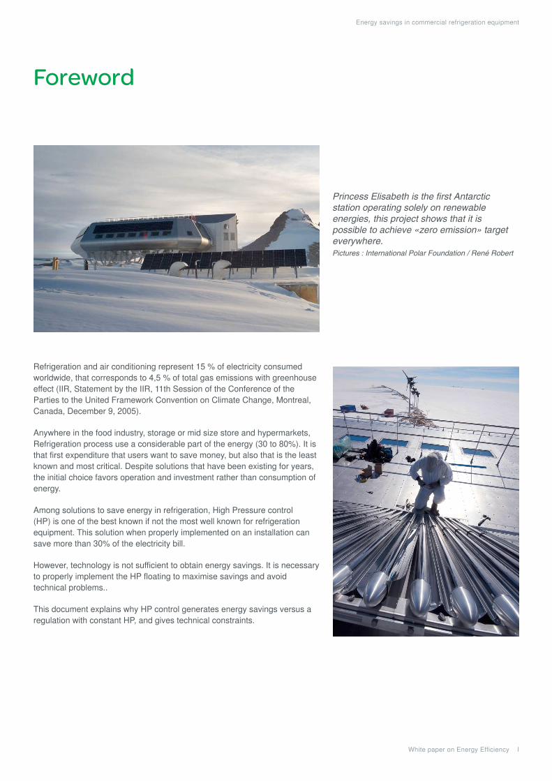
Refrigeration and air conditioning represent 15 % of electricity consumed worldwide, that corresponds to 4,5 % of total gas emissions with greenhouse effect (IIR, Statement by the IIR, 11th Session of the Conference of the Parties to the United Framework Convention on Climate Change, Montreal, Canada, December 9, 2005).
Anywhere in the food industry, storage or mid size store and hypermarkets, Refrigeration process use a considerable part of the energy (30 to 80%). It is that first expenditure that users want to save money, but also that is the least known and most critical. Despite solutions that have been existing for years, the initial choice favors operation and investment rather than consumption of energy.
Among solutions to save energy in refrigeration, High Pressure control (HP) is one of the best known if not the most well known for refrigeration equipment. This solution when properly implemented on an installation can save more than 30% of the electricity bill.
However, technology is not sufficient to obtain energy savings. It is necessary to properly implement the HP floating to maximise savings and avoid technical problems..
This document explains why HP control generates energy savings versus a regulation with constant HP, and gives technical constraints.
White paper on Energy Efficiency I
Energy savings in commercial refrigeration equipment
Princess Elisabeth is the first Antarctic station operating solely on renewable energies, this project shows that it is possible to achieve «zero emission» target everywhere.Pictures : International Polar Foundation / René Robert

Introduction
HP control is a paradoxical solution for energy saving. It might be the best known among energy saving solution, but it is unknown in its operation constraints and limits.
Technological implementation of HP control is relatively easy. However adjustments, and adaptation of the installation to maximize energy savings, are more critical and are seldom implemented. Some HP control installed on refrigerating units does not generate any energy savings, because they are poorly adjusted or not adjusted at all. Others lead to technical problems and, instead of solving these problems, they were abandoned.
This white paper overviews the components of a commercial refrigeration system participating in the HP flow control. An explanation is given on the HP and by what means it is regulated.
The mode of HP historical state of art regulation is presented, then the HP control. Physical implementation will be discussed.
Reasons why HP control generate energy savings are explained and illustrated by two examples.
In a little more technical annex, malfunctions which may occur due to improper implementation of the HP flow control are treated.
White paper on Energy Efficiency II
Energy savings in commercial refrigeration equipment

Operation of a commercial refrigeration system

White paper on Energy Efficiency 1
Energy savings in commercial refrigeration equipment
commercial refrigeration system
Constitution A refrigeration system is a thermodynamics cycle which transports the heat from cold storage, via evaporator, to the outside via condensor (Figure 1 shows a refrigeration system to locate devices).
To understand succintly the benefits and operation (In summary) of HP control it is not necessary to fully understand the operation of the refrigeration installation.
CompressorsThe compressor is the heart of the circuit, while it compresses the gas it provides the flow necessary for the cycle. Generally the compressor consumes the major portion of the energy. Its consumption is not constant and depends on several variables, most important are the low and high pressures. Some compressors are equipped with a mechanical device to reduce cooling capacity. The use of these partial load devices affects the compressor performance.
In terms of energy consumption, the most useful is the COP (Coefficient Of Performance). The COP takes into account variation of internal compressor efficiencies and the refrigeration cycle status. It is therefore necessary to have the operating status associated with the COP to be able to judge. (Example: -10 ° C / +35 ° C).
COP is the ratio of the cooling capacity produced (or useful) to the consumed electrical power. The COP operates in the same direction as efficiency.
There are several types of the compressors, most representative are:
recriprocating compressors,
scroll compressors,
screw compressors.
The following explanation is applicable to these 3 types of compressors.
Note : there are some specific characteristics on certain compressors.
CondensersThe condensers function is to dissipate calories. It is usually on the roof or outside. It can be used to heat water for an other use.
We can distinguish four categories of condensers :
dry condensers,
evaporative condensers,
adiabatic condensers,
hybrid condensers.
Water-cooled condensers
lost water condensers,
opened circuit cooling tower,
closed circuit cooling tower,
hybrid cooling tower,
dry air cooler,
adiabatic air cooler,
heating networks or intermediate heating networks.
Evaporative condenser or other gas heater
HP flow control principle can be applied to all these condensers (except evaporative condensers and heating networks), but explanations given in this document are primarily applicable to dry air coolers and condensers. There are some adaptations needed to make it applicable to other condensers.
ExpansionCompressor
Condenser
Evaporator
Fig.1 Representation of a refrigerating system

White paper on Energy Efficiency 2
Energy savings in commercial refrigeration equipment
High pressure
HP is created by the balance between the heat to be dissipated in red on the chart, and cooling capability in green.
The system must dissipate a quantity of heat which depends on the instantaneous cooling power and the compressors efficiency.
The condenser can dissipate a certain amount of calories depending on its operating conditions: The highest temperature difference between cooler and fluid, which is the cooling capability.
Pressure can also be derived from the saturation temperature (temperature from which the liquefied refrigerant evaporates or the gaseous refrigerant condenses). This temperature increases as the pressure increases. According to the fluid in the system, a HP at 40°C will not have the same pressure.
On the graph, it is clear that when the HP temperature is equal to the outside temperature, heat which can be dissipated is equal to zero.
When the HP increase the temperature difference (between the external and the fluid temperature). Thus the heat rejected by the condensor (in green) is also increased.
For the compressors (in red), when the HP increase, the heat to reject is also increase but slower.
The steady state for HP, is when the heat rejected by the compressor and the heat rejected by the condensor are same.
In order to control this balance, the condenser capability is adjusted by controlling the cooling fans. Increasing the amount of airflow across the condenser, the performance of the condenser increases and vice versa as shown in the figure 3.
Of the many variables that effect the dissipation of heat by the condenser, the only one we can control is the airflow across the condenser coil.
HP control consists in regulating the condensing pressure value to obtain the lowest consumption of the compressor/condensers couple (and auxiliaries).
This is definitely not lower the HP to the minimum.
Fig.2 High pressure according to the evacuable powers
Fig.3 Flow influence of the fans
HP balance
pow
er to
be
diss
ipat
ed b
y th
e co
nden
ser
pow
er to
be
diss
ipat
ed b
y th
e co
nden
ser
cool
ing
capa
bilit
yco
olin
g ca
pabi
lity
Text = HP
Text = HP
High Pressure
High Pressure

HP control modes
White paper on Energy Efficiency 3
Energy savings in commercial refrigeration equipment
HP controlReducing HP is interesting in terms of energy consumption: when HP decreases the compressor COP increases, and vice versa. Figure 5 shows the COP as a function of the condensation temperature for a screw compressor, COP variation is clearly visible. In the example, it jumps from 1.9 at -10 ° C / +50 ° C to 4.7 at -10 ° C / +20 ° C i.e. a variation of 62%.
Figure 6 gives the percentage gain (or loss) on COP for variations of one degree of temperature condensation (given in Kelvin) according to the HP and for various evaporation temperatures. All compressors do not react the same way, it is therefore necessary to use the characteristics of the compressors in place to correctly assess the energy savings.
1
2
3
0
1
2
3
4
5
6
7
20 25 30 35 40 45 502.0%
2.5%
3.0%
3.5%
4.0%
4.5%
20 25 30 35 40 45 50
This method is the most used control method; however, with the implementation of HP control being easier and the added benefits this method is slowly be replaced. It is to regulate HP at a constant value that can be held throughout the year. For a constant HP, it is necessary to use a regulation with neutral zone or a PID. The most common is the use of pressure switch or hysteresis controller creating steps in the HP regulation (Figure 4).
HP is not really regulated at a constant value; it will vary uncontrolled according to the outside temperature, the heat to be dissipated and the number of fans required to accomplish this will most often NOT be performing at the peak efficiency.
The implementation of the HP modes is not identical with all condensers. It is understandable that the control is not implemented or controlled in the same way with a dry condenser or a cooling tower. However, the methods described below are applicable with some modifications.
High Pressure
Num
ber
of fa
ns
Fig.4 HP variation according to the number of fans
Fig.5 COP variation vs HP for a screw compressor
LP=5°CLP=5°C
LP=0°CLP=0°C
LP=-10°CLP=-10°C
Fig.6 COP variation (K in%) vs HP
HP - Condensation saturating temperature [°C]HP -Condensation saturating temperature [°C]
CO
P v
aria
tion
vs H
P te
mpe
ratu
re [%
/K]
Com
pres
sor
CO
P
Constant HP or with hysteresis

White paper on Energy Efficiency 4
Energy savings in commercial refrigeration equipment
HP control modes
However, to reduce the HP, it is mandatory to operate more fans. Energy savings is thus less than those calculated on the compressor.
It is necessary to calculate the COP on the compressor and condenser as a whole to specify HP control. The use of fans should be made whith definite purpose and with absolute need. Sometimes savings made on the compressor can be offset or exceeded by the use of fans.
The graph of Figure 7 demonstrates the existence of an optimum. This phenomenon often occurs on installations operating below 50% of full load.
To summarize, HP control consists in regulating the condensation pressure at a value in order to obtain the lowest power consumption of the compressor / condenser couple (and auxiliaries).
This is definitely not to lower the maximum HP, which could on top of an increase of the power consumption cause malfunctions of the installation. (See appendix)
HP
Inpu
t ele
ctric
al p
ower
Compressor + condenser electrical powerCondenser electrical powerCompressor electrical power
Fig.7 Powers optimization of the compressor/condenser
Optimum.

White paper on Energy Efficiency 5
Energy savings in commercial refrigeration equipment
Concretely on the field
Installation is relatively simple (see example in figure 8).The controller embedding with HP control algorithms, receives HP information of the refrigerant, the outside temperature and then, processes this information.
The controller converts pressure to temperature (depending on refrigerant fluid used).
It calculates the differential with the outside temperature.
This differential is the parameter to control. It is used in a PID function(it is a control block) that gives the percentage of condenser power to use.
This percentage is translated into the number of fans required to operate.
T
P
Power electrical wiring
Sensors signalRemote control
Refrigerate piping
Fig.8 Installation example
White paper on Energy Efficiency 6
Energy savings in commercial refrigeration equipment
Application on storage system
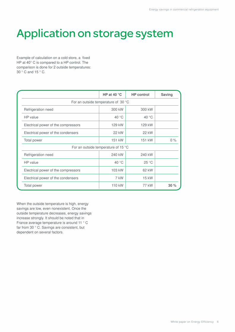
Example of calculation on a cold store, a fixed HP at 40° C is compared to a HP control. The comparison is done for 2 outside temperatures: 30 ° C and 15 ° C.
When the outside temperature is high, energy savings are low, even nonexistent. Once the outside temperature decreases, energy savings increase strongly. It should be noted that in France average temperature is around 11 ° C far from 30 ° C. Savings are consistent, but dependent on several factors.
HP at 40 °C HP control Saving
For an outside temperature of 30 °C
Refrigeration need 300 kW 300 kW
HP value 40 °C 40 °C
Electrical power of the compressors 129 kW 129 kW
Electrical power of the condensers 22 kW 22 kW
Total power 151 kW 151 kW 0 %
For an outside temperature of 15 °C
Refrigeration need 240 kW 240 kW
HP value 40 °C 25 °C
Electrical power of the compressors 103 kW 62 kW
Electrical power of the condensers 7 kW 15 kW
Total power 110 kW 77 kW 30 %

Generic application
White paper on Energy Efficiency 7
Energy savings in commercial refrigeration equipment
Figures 9 and 10 give the power consumption of the compressor and condenser under different outdoor temperatures and regulation requirements. Each curve represents the power absorbed by the compressor and condenser for several external temperatures.
In X-coordinate the difference between the outside temperature and the HP appears. The addition of the value in X-coordinate and the outside temperature gives the HP value.
This chart allows you to define what algorithms is the best suited to reduce the power requirements to the minimum.
In this example, when the installation operates at full cooling capacity (Figure 9), that is to say 500 kW of cold, running with all fans is less energy demanding whatever the outside temperature.
When the installation is running at partial load i.e. 40% load (Figure 10), input power decreases with the reduction of HP. From the optimal HP, power consumption increases while HP continues to decline. Savings are about 1.5% / K at right of the optimal HP and -1.5% / K at the left of the optimal HP. These values are not generic for all installations.
An optimal value of HP emerges: the goal of a HP control will be to regulate the installation at this value.
Note: that these values are for a given installation, it is necessary to analyze each installation to determine the optimum HP.
120
140
100
160
180
200
220
240
260
280
5 6 7 8 9 10 11 12 13 14 15
5 6 7 8 9 10 11 12 13 14 1540
50
60
70
80
90
100
110
120
Fig.9 Electric output of the whole at 500kW
Fig.10 Electric efficiency of the whole at 500kW
Tout =30 °C
Tout =30 °C
Tout =20 °C
Tout =20 °C
Tout =10 °C
Tout =10 °C
Abs
orbe
d po
wer
cp+
cd [k
W]
Abs
orbe
d po
wer
cp+
cd [k
W]
Temperature gap between outside and condensation [K]
Temperature differential between outside and condensation [K]
Temperature differential for optimum HP
This example will help to show the impact of two factors - the outside temperature and the load of the installation - which influences the performance of installation and those of the HP control.
The example installation, produces 500 kW of cold when running at its maximum speed, i.e. a Low Pressure (LP) at -10 ° C and a HP at 50 ° C. Compressors have a COP rated 3.4 at -10 / +30 ° C. The condenser ventilation power is 40 kW; which dissipates 685 kW with a differential of 10 ° C. The minimum HP temperature is limited to 20 ° C for technical constraints.
SavingOverconsumption

Conclusion
White paper on Energy Efficiency 8
Energy savings in commercial refrigeration equipment
In today’s climate, energy saving solutions are demanded. Environmental aspect is sometimes not sufficient to justify the huge required investments. Solutions as HP flow control have the benefit of reducing the environmental impact not to mention the financial aspect.
HP flow control remains an effective and current solution for energy savings. There may be differences between solutions and their implementations..
To improve the return on investment, good commissioning must not be forgotten.
This solution, according to the installations, is not very expensive; however it can have very significant energy savings, exceeding 30%. HP control is the solution with the best return on investment for refrigeration.
Today, all new installations must have an effective HP control.

Schneider Electric SA
35 rue Joseph Monier F-92500 Rueil Malmaison - France Phone: + 33 (0) 1 41 29 70 00 Fax: + 33 (0) 1 41 29 71 00 http://www.schneider-electric.com
Document Number WPB5101001EN
© 2
010
Sch
neid
er E
lect
ric. A
ll rig
hts
rese
rved
.
11/2010
This document has beenprinted on recycled paper