High Pressure CO2 Controller Installation and … Rev 0 01-DEC-2014 High Pressure CO2 Controller...
56
026-1731 Rev 0 01-DEC-2014 High Pressure CO2 Controller Installation and Operation Manual
Transcript of High Pressure CO2 Controller Installation and … Rev 0 01-DEC-2014 High Pressure CO2 Controller...

026-1731 Rev 0 01-DEC-2014
High Pressure CO2 Controller Installation and Operation Manual


Emerson Climate Technologies Retail Solutions1065 Big Shanty Road NW, Suite 100
Kennesaw, GA 30144
Phone: 770-425-2724Fax: 770-425-9319


Table of Contents1 OVERVIEW ................................................................................................................................................................... 1
1.1 THE HIGH PRESSURE CO2 CONTROLLER I/O POINTS................................................................................................... 11.2 INDEPENDENT SYSTEM CONTROL.................................................................................................................................. 2
2 HARDWARE SETUP.................................................................................................................................................... 3
2.1 CONNECTIONS............................................................................................................................................................... 32.2 INPUTS AND OUTPUTS .................................................................................................................................................. 42.3 TECHNICAL SPECIFICATIONS ........................................................................................................................................ 6
2.3.1 Analog Inputs ........................................................................................................................................................ 62.3.2 Digital Inputs ........................................................................................................................................................ 62.3.3 Analog Outputs ..................................................................................................................................................... 72.3.4 Digital Outputs...................................................................................................................................................... 72.3.5 Dimensions............................................................................................................................................................. 82.3.6 Wiring Diagrams.................................................................................................................................................... 92.3.7 Electrical Specifications ..................................................................................................................................... 102.3.8 Plastic Enclosure ................................................................................................................................................ 102.3.9 USB-Ethernet Adapter ........................................................................................................................................ 10
2.4 POWERING THE HIGH PRESSURE CO2 CONTROLLER .................................................................................................. 102.4.1 Choosing Transformer Sizes ................................................................................................................................ 102.4.2. Wire Types and Maximum Distances................................................................................................................. 11
3 THE MODBUS NETWORK ...................................................................................................................................... 12
3.1. WIRING TYPES............................................................................................................................................................ 123.1.1. Daisy Chains ....................................................................................................................................................... 123.1.2. Network Addressing - Visograph ........................................................................................................................ 14
3.1.2.1. Connecting the Visograph................................................................................................................................................. 143.1.2.2. Visograph Navigation ....................................................................................................................................................... 153.1.2.3. Setting the MODBUS Address ......................................................................................................................................... 153.1.2.4 Versions ............................................................................................................................................................................. 16
3.2 MODBUS TERMINATION............................................................................................................................................ 16
4 INPUTS AND OUTPUTS SETUP.............................................................................................................................. 17
4.1 INPUTS SETUP .............................................................................................................................................................. 174.1.1 Wiring Analog and Digital Inputs........................................................................................................................ 17
4.2 OUTPUTS SETUP .......................................................................................................................................................... 204.2.1 Wiring Relay and Analog Outputs ....................................................................................................................... 20
5 HIGH PRESSURE CO2 CONTROLLER STATUS LED....................................................................................... 21
5.1 POWER ON (PWR ON) LED....................................................................................................................................... 225.2 LED1 NETWORK STATUS............................................................................................................................................ 22
6 SOFTWARE OVERVIEW ......................................................................................................................................... 22
6.1 HIGH PRESSURE VALVE CONTROL.............................................................................................................................. 226.1.1 HPV Subcritical Mode (Normal) ......................................................................................................................... 236.1.2 HPV Transcritical Mode (Normal) ...................................................................................................................... 246.1.3 HPV Heat Reclaim ............................................................................................................................................... 25
6.2 BYPASS GAS VALVE CONTROL ................................................................................................................................... 26
7 SAFETY OPERATION PARAMETERS FOR HIGH PRESSURE AND BYPASS GAS VALVES .................. 28
Table of Contents • v

7.1 LOW PRESSURE OPERATION ........................................................................................................................................ 287.1.1 Normal Operation ................................................................................................................................................ 28
7.2 HIGH PRESSURE OPERATION ....................................................................................................................................... 287.2.1 Normal Operation ................................................................................................................................................ 28
7.3 SENSOR FAILURE ......................................................................................................................................................... 297.4 EMERGENCY SHUTDOWN ENABLE INPUT .................................................................................................................... 29
8 VALVE CALIBRATION FEATURE ........................................................................................................................ 30
9 ALARMS....................................................................................................................................................................... 31
10 VISOGRAPH.............................................................................................................................................................. 32
10.1 STATUS SCREEN......................................................................................................................................................... 3210.1.1 Main Menu and Status Screens .......................................................................................................................... 32
10.2 CONFIGURATION SETUP SCREEN ............................................................................................................................... 3310.2.1 Main Menu to Configuration Screens ................................................................................................................ 3310.2.2 General Configuration Screens.......................................................................................................................... 3410.2.3 Valve Configuration Screens.............................................................................................................................. 3410.2.4 I/O Configuration Screens ................................................................................................................................. 3510.2.5 XEV20D Configuration Screens......................................................................................................................... 37
10.3 OVERRIDE SCREEN .................................................................................................................................................... 37
11 HIGH PRESSURE CO2 CONTROLLER RANGES AND DEFAULT SETPOINT PARAMETERS............. 39
12 XEV20D SETUP AND NETWORK CONNECTION ............................................................................................ 41
13 STEPPER VALVE ACTUATOR QUICK REFERENCE GUIDE XEV20D ...................................................... 42
13.1. GENERAL WARNINGS ............................................................................................................................................... 4213.2 GENERAL DESCRIPTION ............................................................................................................................................. 4313.3 ABSOLUTE MAXIMUM POWER................................................................................................................................... 4313.4 WIRING DIAGRAMS.................................................................................................................................................... 44
13.4.1 One Valve Configuration ................................................................................................................................... 4413.4.2 Two Valve Configuration ................................................................................................................................... 44
13.5 VALVE CONNECTIONS ............................................................................................................................................... 4413.6 SERIAL LINE - LAN BUS ........................................................................................................................................... 4513.7 LED DESCRIPTIONS ................................................................................................................................................... 4713.8 XEV20D TECHNICAL SPECIFICATIONS ..................................................................................................................... 47
vi • Name of Manual 026-1731 Rev 0 01-DEC-2014

1 OverviewThe High Pressure CO2 controller (P/N 818-9010)
application is a standalone controller that operates the High Pressure Valve (HPV) and the Bypass Gas Valve (BGV) in a Booster Transcritical CO2 system. The controller has a heat reclaim feature, safety pa-rameter operation for the flash gas receiver tank and calibration feature for the HPV and BGV.
CAUTION! GND is Common, not earth ground. Do not earth ground this device.
1.1 The High Pressure CO2 Controller I/O Points
The board has 6 analog inputs and 11 digital in-puts, with default configurations pre-loaded for quick connection to for gas cooler pressure outlet, gas cool-er temperature, flash gas receiver pressure and enable digital input. Its 8 relay outputs, rated 2.0 amps max, are used for activating and deactivating alarms. Its 4 analog outputs may be used for a 0-10 volt signal for external valve driver for either the HPV or BGV.
Figure 1-1 - High Pressure CO2 Controller
The High Pressure CO2 controller supports local physical inputs and outputs and communicates with the E2 controller (version 3.00 and higher) via the RS485 MODBUS network.
• 1

1.2 Independent System Control
The High Pressure CO2 controller can control the HPV and BGV in a refrigeration Booster Transcritical CO2 System. However, the High Pressure CO2 con-troller is designed to interface with an E2. Network-ing the High Pressure CO2 controller to a central controller also allows you to view status on E2 and UltraSite32 Site Manager status screens, report alarms, and log point values.
The High Pressure CO2 controller configuration can be programmed through the E2 front panel.
2 • High Pressure CO2 Controller Installation and Operation Manual 026-1731 Rev 0 01-DEC-2014

2 Hardware Setup
Figure 2-1 - High Pressure CO2 Controller
2.1 Connections
Connector Description
Connector for 24VAC/DC power supplyAnalog inputs (Pb1 - Pb6, PbC)Additional power: +5VDC, +12VDC, Common (-)Analog outputs (Out1 - Out4, Common)
24VAC/DC digital inputs: DI1 - DI11, Common (-)
Connector for remote terminal (VISOGRAPH), maximum 1 terminal per controller.RS485 Slave connectorSerial port connector (LAN or RS485)
USB port for downloads (BIOS, ISaGRAF® application, maps of parameters, remote display applications, network configuration, and Web site) and uploads (log files).Connection with the computer via a USB-ETH converter
Table 2-1 - Connections and Descriptions
• 3

2.2 Inputs and Outputs
Digital relay outputs4 NO relays, 2 common
Digital relay outputs4 NO relays, 2 common
Connector Description
Table 2-1 - Connections and Descriptions
Input Number
Type of Input Description
1 Supply Reference “-“/Common power (24VAC or 24VDC)
2 Pb1 Configurable analog input 1 (NTC, PTC, 0 - 20mA, 4 - 20mA, 0 - 10V, 0 - 1V, 0 - 5V, DI)
3 Pb2 Configurable analog input 2 (NTC, PTC, 0 - 20mA, 4 - 20mA, 0 - 10V, 0 - 1V, 0 - 5V, DI)
4 Pb3 Configurable analog input 3 (NTC, PTC, 0 - 20mA, 4 - 20mA, 0 - 10V, 0 - 1V, 0 - 5V, DI)
5 +12V Additional power +12VDC
6 +5V Additional power +5VDC
7 Out1 Analog output 1, 0 - 10V, 4 - 20mA, Relay
8 Out2 Analog output 2, 0 - 10V, 4 - 20mA, Relay
9 Supply Reference “+” power supply (24VAC or 24VDC)
10 Pb4 Configurable analog input 4 (NTC, PTC, 0 - 20mA, 4 - 20mA, 0 - 10V, 0 - 1V, 0 - 5V, DI)
11 Pb5 Configurable analog input 5 (NTC, PTC, 0 - 20mA, 4 - 20mA, 0 - 10V, 0 - 1V, 0 - 5V, DI)
12 Pb6 Configurable analog input 6 (NTC, PTC, 0 - 20mA, 4 - 20mA, 0 - 10V, 0 - 1V, 0 - 5V, DI)
13 PbC Common analog inputs (NTC, PTC, DI)
14Voltage
Common(-)
Additional power reference 5VDC and 12VDC, analog inputs (0 - 20mA, 4 - 20mA, 0 -10V, 0- 1V, 0 - 5V), analog outputs
15 Out3 Analog output 3, 0 - 10V, 4 - 20mA, Relay
16 Out4 Analog output 4, 0 - 10V, 4 - 20mA, Relay
20 DI1 Digital input 1, 24VAC/DC28 DI9 29 DI10 30 DI11
21 DI2 Digital input 2, 24VAC/DC
Table 2-2 - Description of the Inputs and Outputs
4 • High Pressure CO2 Controller Installation and Operation Manual 026-1731 Rev 0 01-DEC-2014

22 DI3 Digital input 3, 24VAC/DC
23 DI4 Digital input 4, 24VAC/DC
24 DI5 Digital input 5, 24VAC/DC
25 DI6 Digital input 6, 24VAC/DC
26 DI7 Digital input 7, 24VAC/DC
27 DI8 Digital input 8, 24VAC/DC
28 DI9 Digital input 9, 24VAC/DC
29 DI10 Digital input 10, 24VAC/DC
30 DI11 Digital input 11, 24VAC/DC
31Digital
Common(-)
Reference “-” for digital inputs from1 to 11 (if version with dry contacts, this input has to be used only as common for the digital inputs)
40 C Common relays 1, 2, 3 and 4
41 C Common relays 1, 2, 3 and 4
42 RL1 Relay 1 normally open contact
43 RL2 Relay 2 normally open contact
44 RL3 Relay 3 normally open contact
45 RL4 Relay 4 normally open contact
46 RL5 Relay 5 normally open contact
47 C Common relays 5, 6, 7 and 8
48 C Common relays 5, 6, 7 and 8
49 RL6 Relay 6 normally open contact
50 RL7 Relay 7 normally open contact
51 RL8 Relay 8 normally open contact
60 Remote Display Connection for VISOGRAPH remote terminal (Vnr)
61 Remote Display Connection for VISOGRAPH remote terminal (+)
62 Remote Display Connection for VISOGRAPH remote terminal (-)
63 RS485 Slave RS485 Slave connection (-)
Input Number
Type of Input Description
Table 2-2 - Description of the Inputs and Outputs
• 5

2.3 Technical Specifications2.3.1 Analog Inputs
Table 2-3 - Analog Inputs
Analog conversion type:
10-bit A/D converter
Number of Inputs:
6
Type of analog input: (configurable via software parameter)
NTC Emerson Retail Solutions (-50T110°C; 10KΩ±1% at 25°C)PTC Emerson Retail Solutions (-55T115°C; 990Ω±1% at 25°C)Digital input (potential free contact)Voltage: 0 - V, 0 - 5V, 0 - 10V (input resistance 3.7KΩ)Current: 0 - 20mA, 4 - 20mA (input resistance 100Ω)
Accuracy: NTC, PTC: ±10-1V: ±20mV0-5V: ±100mV0-10V:±200mV2-20mA, 4-20mA: ±0.30mA
Additional power:
+12V: 200mA in total (between +12V and analog outputs)+5V: 100mA
CAUTION! Any inputs that are powered with a voltage that differs from that supplied by the device (+12V or +5V) must be pow-
ered separately with another transformer (do not use the same secondary of the controller’s power) in or-der to prevent the inputs from malfunctioning or be-ing damaged.
2.3.2 Digital Inputs
Table 2-4 - Digital Inputs
Type: (configurable via software parameter)
Opto-insulated live contact (24VAC/DC) External power 24VAC/DC ±20%
Number of Inputs:
11
Digital input status variation detection time:
100ms (in any case it depends on the cycle time set by the user in the given application)
CAUTION! Use another transformer (do not use the same secondary of the control-ler’s power) in order to prevent the inputs
from malfunctioning or being damaged.
64 RS485 Slave RS485 Slave connection (+)
65 LAN LAN Connection (-)
66 LAN LAN Connection (+)
Input Number
Type of Input Description
Table 2-2 - Description of the Inputs and Outputs
6 • High Pressure CO2 Controller Installation and Operation Manual 026-1731 Rev 0 01-DEC-2014

2.3.3 Analog Outputs
Table 2-5 - Analog Outputs
Type: Non opto-insulated internal power
Number of Outputs:
4
Type of analog output:(configurable via software parameter)
4 configurable outputs 0-10VDC 4-20mA (Out1 - Out4)
Maximum load: 40mA (Out1 - Out4) max with configured outputs 0-10VDC400Ω max with configured outputs 4-20mA22Ω per live analog output
Accuracy: Out1 - Out4: ±2% full scale
Resolution: 8-bit
CAUTION! The electrical devices con-trolled by these analog outputs must be pow-ered separately with another transformer
(do not use the same secondary of the controller’s power) in order to prevent the outputs from malfunc-tioning or being damaged.
2.3.4 Digital Outputs
Table 2-6 - Digital Outputs
Type: Relays with NO contacts
Number of Outputs:
8
Type of analog output:(configurable via software parameter)
Relays with normally open contact
Maximum load:
5A(250VAC) SPST 5(2)A
CAUTION! Verify the capacity of the output used. There is double insulation between the digital outputs and the low voltage of the rest
of the circuit. Do not use different voltages for the various groups of relays or within each group.
• 7

2.3.5 Dimensions
Figure 2-2 - Dimensions
8 • High Pressure CO2 Controller Installation and Operation Manual 026-1731 Rev 0 01-DEC-2014

2.3.6 Wiring Diagrams
Figure 2-3 - Wiring Diagrams
NOTE: To ensure control in case of a power failure, it is recommended that a UPS be used on the High Pressure CO2 controller.
• 9

2.3.7 Electrical Specifications
Table 2-7 - Electrical Specifications
Power Supply: 24VAC +10/-15%, 50/60Hz, 20 - 36VDC
Consumption: From 30VA (VAC), From 25W (VDC)
Connectors:
Molex connectors with low voltage wiring (for IPS100D and IPS400D)Phoenix quick coupling connectors for low voltage (for IPS200D)STELVIO 90° screw connectors for digital outputs (250VAC, 6A max)
Microprocessor: AT91SAM9260 32-bit 200Mhz
Permanent FLASH memory:
16Mb, in 8-bit chunks
RAM: 2x128Kb, in 16-bit chunks
Internal clock: Standard
2.3.8 Plastic Enclosure
Table 2-8 - Enclosure Specifications
Mount:
On a DIN rail (EN 50022, DIN 43880) Fastened with screws via the removable plastic flaps.
Material: PC-ABS Thermoplastic
Self-extinguishing: V0 (UL94)
Comparative Tracking Index (CTI):
300V
Color: Black or White, depending on the model
2.3.9 USB-Ethernet Adapter
The IPS range of programmable controllers can be connected to a computer via an external adapter. This adapter must be used in the processing environment for the application download in the controller. This adapter is not set up for fixed or continuous connec-tion. If the adapter should be kept connected continu-ously, the room temperature must not exceed 50°C (122°F).
Figure 2-4 - USB-Ethernet Adapter
2.4 Powering the High Pressure CO2 Controller
Retail Solutions supplies a wide variety of 24VAC transformers with varying sizes without center taps. (Table 2-9) shows the transformer sizes and are non- center-tapped.2.4.1 Choosing Transformer Sizes
The transformer used to power the High Pressure CO2 controller should have at least a 30VA rating. The High Pressure CO2 controller should not share a transformer with any other devices. Figure 2-5 shows how to wire the transformer to the High Pressure CO2 controller.
Table 2-9 - Compatible Transformers with CO2 Controller
Transformer P/N VA Rating Primary Voltage
640-0041 50 VA 110 VAC
640-0042 50 VA 220 VAC
10 • High Pressure CO2 Controller Installation and Operation Manual 026-1731 Rev 0 01-DEC-2014

Neither side of the secondary should be connected to ground. Also, do not connect the center tap (if pro-vided on the transformer) to ground. The entire sec-ondary of the transformer should be isolated from any ground.
Figure 2-5 - Non-Center Tapped Transformer Wiring
2.4.2. Wire Types and Maximum Distances
For powering I/O boards, use only the listed wire types in Table 2-10. Two-conductor non-shielded cables are the recommended wire for connecting the transformer to the High Pressure CO2 controller. Shielded cable should not be used for power wiring. The center tap should be left disconnected if present on the transformer.
Table 2-10 - Power Wiring Types
Power Wiring Types14 AWG Belden 949518 AWG Belden 9495
The wire length from the transformer determines the type wire gauge used. In most cases, the distance between the High Pressure CO2 controller and the transformer that supplies power to it is not enough to be of concern; however, it is very important NOT to exceed this maximum wire length or the controller will not operate correctly.
Use these formulas to determine if the wire gauge you are using fits within specification:
Table 2-11 - Power Wire Lengths
14 AWG:Feet = 1920/VA18 AWG:Feet = 739/VA(VA is the total VA rating of the controller)For example, if you had an 80 VA load:14 AWG: 24 ft.18 AWG: 9 ft. (rounded down)
Sensors requiring 24VAC should not be powered from the same transformer that is powering the input board. Any devices that will be connected to the High Pressure CO2 controller inputs or outputs must be powered with a separate 24VAC transformer.
• 11

3 The MODBUS Network
Although the High Pressure CO2 controller can operate as a stand-alone controller, it relies on an E2 unit for advanced features such as remote dial-in/dial-out, logging, and alarm control. The High Pressure CO2 controller uses an RS485 network connection to communicate with E2 site controllers.
3.1. Wiring TypesRetail Solutions specs Belden #8761 shielded
twisted pair cables for use as MODBUS wiring (or Belden #82761 and Belden #88761 for plenum installations).
If the recommended cable is not available in your area, be sure the wiring meets or exceeds the following specs:
Shielded? Yes
Conductor Type Twisted Pair
Gauge 18 - 24 AWG
Capacitance between signal wires
31 pF/ft or less(9.45 m) or less
Capacitance between signal and shield
59 pF/ft or less(17.98 m) or less
Nominal Impedance 12050
3.1.1. Daisy ChainsConnect the MODBUS network cable to the three-
terminal connector on the E2 COM port you wish to assign as MODBUS. Reverse the polarity of +/- on the RS485 cable between the E2 and the High Pres-sure CO2 controller.
12 • High Pressure CO2 Controller Installation and Operation Manual 026-1731 Rev 0 01-DEC-2014
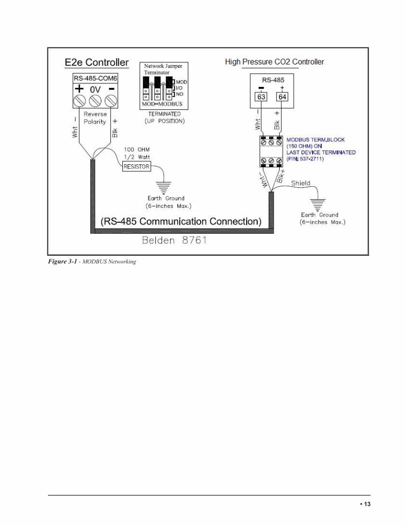
Figure 3-1 - MODBUS Networking
• 13

3.1.2. Network Addressing - VisographThe network address makes a board unique from other boards on the network of the same type. This allows
the site controller to find it and communicate with it easily. The network address of the High Pressure CO2 controller is set using add-on devices called visographs
(P/N 818-9002).
3.1.2.1. Connecting the Visograph
The visograph is connected with a 3-wire connection on pins 60, 61, and 62.
Figure 3-2 - Network ID Settings
CAUTION: The High Pressure CO2 controller may be damaged if the wires are crossed when connecting the visograph, especially if pin 60
(Vnr) is accidentally connected to + or –
14 • High Pressure CO2 Controller Installation and Operation Manual 026-1731 Rev 0 01-DEC-2014

3.1.2.2. Visograph Navigation
• Four status menu items are available to choose from within the status menu.
• Press corresponding button along the bottom (T1-T8) to navigate to desired item.
Figure 3-3 - Visograph Menu
3.1.2.3. Setting the MODBUS Address
To setup the MODBUS settings, you will have to enter the configuration menu from the main menu. The configuration menu is password protected.
Figure 3-4 - Main Menu
From main menu, press the T1+ T3 +T8 buttons together and hold until you see the Configuration screen.
Figure 3-5 - Configuration Screen
Highlight General Config and press the ENTER key (T3).
Figure 3-6 - General Config Screen
Press T8 to arrow over to the next screen.
Figure 3-7 - General Config Screen
Using the UP and DOWN arrows (T3 andT5), highlight the field and press T4 to change the
address to the desired value.
• 15

Press ENTER to save new address.The address field should stop blinking.
Press T1 (MENU) to go back to the previous menu.
NOTE: When the MODBUS address is changed, the High Pressure CO2 controller needs to be rebooted.
3.1.2.4 VersionsThe High Pressure CO2 controller and Visograph ver-
sions are also shown on the Controller Info screen.To see the High Pressure CO2 controller version,
please see the Visograph Section of the Status screen.
3.2 MODBUS TerminationIf the High Pressure CO2 controller is located at the
physical end of the MODBUS network, install the MOD-BUS termination block (P/N 537-2711).
16 • High Pressure CO2 Controller Installation and Operation Manual 026-1731 Rev 0 01-DEC-2014

4 Inputs and Outputs Setup
4.1 Inputs SetupThe High Pressure CO2 application has the ability to assign all inputs to be any of the possible options for
an analog input in the application. The analog inputs will have offsets available while the digital inputs will have a polarity option. All input will use physical local input and have a network input from the E2 for backup if avail-able. The default input configuration is:
Table 4-1 - High Pressure CO2 Controller Inputs
Inputs Description Local Network Sensor Type
Pb1 Temperature-Outlet Gas Cooler (T1) Yes Yes NTC
Pb2 Pressure-Outlet Gas Cooler (P1) Yes Yes 0-5V Only
Pb3 Pressure-Receiver (P2) Yes Yes 0-5V Only
TBD Temperature-Bypass Outlet Gas Cooler (T2) Yes Yes NTC
DI1 Reclaim Setpoint Shift (Digital Input) (HTR) Yes Yes 24VAC/DC
DI2 Enable Application/Emergency Shutdown (Digital Input (Enable) Yes Yes 24VAC/DC
DI3 Control Temp Selector (Digital Input) (CTS) Yes Yes 24VAC/DC
The application can use a local or E2 network value if online, but the local value will have priority over the network value. However, if any sensor is in failure mode, its corresponding network value will be used. If no network value is available, refer to Section 7.3, Sensor Failure.
The input assignment will be available from the Visograph local display and the E2.4.1.1 Wiring Analog and Digital
InputsThe analog inputs are located on the same connector
terminal as the controller power supply. Pay attention to the input commons as they are share on terminal 13 (PbC) for temperature probe and terminal 14: Voltage Common (-) for pressure transducer.
CAUTION: Terminal 14 is labeled Voltage Common (-) for use as common and should NOT be earth chassis grounded.
• 17

Figure 4-1 - Analog Input Connectors
CAUTION: Any inputs that are powered with a voltage that differs from that supplied by the High Pressure CO2 controller (+12V
or +5V) must be powered separately with another transformer in order to prevent the inputs from mal-functioning or being damaged. Do not use the same secondary of the controller's power to power the sen-sors.
Terminal Number on Connector Name
1 24VAC Supply (-)
2 Probe Input 1 (default set as T1-Outlet Gas Cooler Temp)
3 Probe Input 2 (default set as P1-Outlet Gas Cooler Pressure)
4 Probe Input 3 (default set as P2-Flash Tank Receiver Pressure)
5 +12VDC
6 +5VDC
7 Analog Output 1 (default set as HPV Stepper Valve 1)
8 Analog Output 2 (default set as BGV Stepper Valve 2)
9 24VAC Supply (+)
10 Probe Input 4
11 Probe Input 5
Table 4-2 - Analog Input Connector Terminals
18 • High Pressure CO2 Controller Installation and Operation Manual 026-1731 Rev 0 01-DEC-2014

The digital inputs are located on the corresponding connector terminal below. Pay attention to the input commons as they are share on terminal 31: Digital Common (-) and the digital inputs are voltage input that can handle 24VAC/DC.
CAUTION: Terminal 31 is labeled Digital Common (-) for use as common and should NOT be earth chassis grounded.
Figure 4-2 - Digital Inputs Connectors
12 Probe Input 6
13 Temperature Common
14 Transducer/Analog Output Common
15 Analog Output 3
16 Analog Output 4
Terminal Number on Connector Name
20 Digital Input 1(default set as HTR-Relcaim Setpoint Shift)
21 Digital Input 2(default set as ENABLE/SHUTDOWN)
22 Digital Input 3(default set as CTS-Control Temp Selector)
23 Digital Input 4
24 Digital Input 5
25 Digital Input 6
Table 4-3 - Digital Input Connector Terminals
Terminal Number on Connector Name
Table 4-2 - Analog Input Connector Terminals
• 19

4.2 Outputs SetupThe High Pressure CO2 application can assign any output to one of the available relay outputs, which have both delays
and polarity configuration definable by a user from the local display and E2. The default relay configuration is:
Table 4-4 - High Pressure CO2 Controller Inputs
Rly Out Description Local Network
RL1 General Alarm Yes Yes
RL2 Low Pressure Alarm Yes Yes
RL3 High Pressure Alarm Yes Yes
RL4 Shutdown Yes Yes
The High Pressure CO2 application has the ability to assign all analog outputs to be any of the possible options for an analog output in the application. It will also have connectivity to an XEV20 (Dual Valve), which will drive two steppers valves using it for a high pressure valve and bypass gas valve. The default configuration is:
Table 4-5 - Analog Outputs
Anlg Out Description Local Network LAN
Out1 Stepper Valve 1 Yes Yes Yes
Out2 Stepper Valve 2 Yes Yes Yes
The relay outputs, analog outputs, and the XEV20 setup or assignment will be available from the local display and the E2. The XEV20 will also provide online status on the Visograph and E2.
4.2.1 Wiring Relay and Analog Outputs
The relay outputs are located on corresponding connector terminal below. There are 2 input relay commons on termi-
26 Digital Input 7
27 Digital Input 8
28 Digital Input 9
29 Digital Input 10
30 Digital Input 11
31 Digital Common
Terminal Number on Connector Name
Table 4-3 - Digital Input Connector Terminals
20 • High Pressure CO2 Controller Installation and Operation Manual 026-1731 Rev 0 01-DEC-2014

nal 40 and 41 (C) for relay 1 through 4.
Figure 4-3 - Relay Output Connectors
The analog outputs are located on the same connector terminal as the controller power supply. Pay attention to the analog outputs commons as they are shared on terminal 14: Voltage Common (-).
Figure 4-4 - Analog Output Connectors
• 21
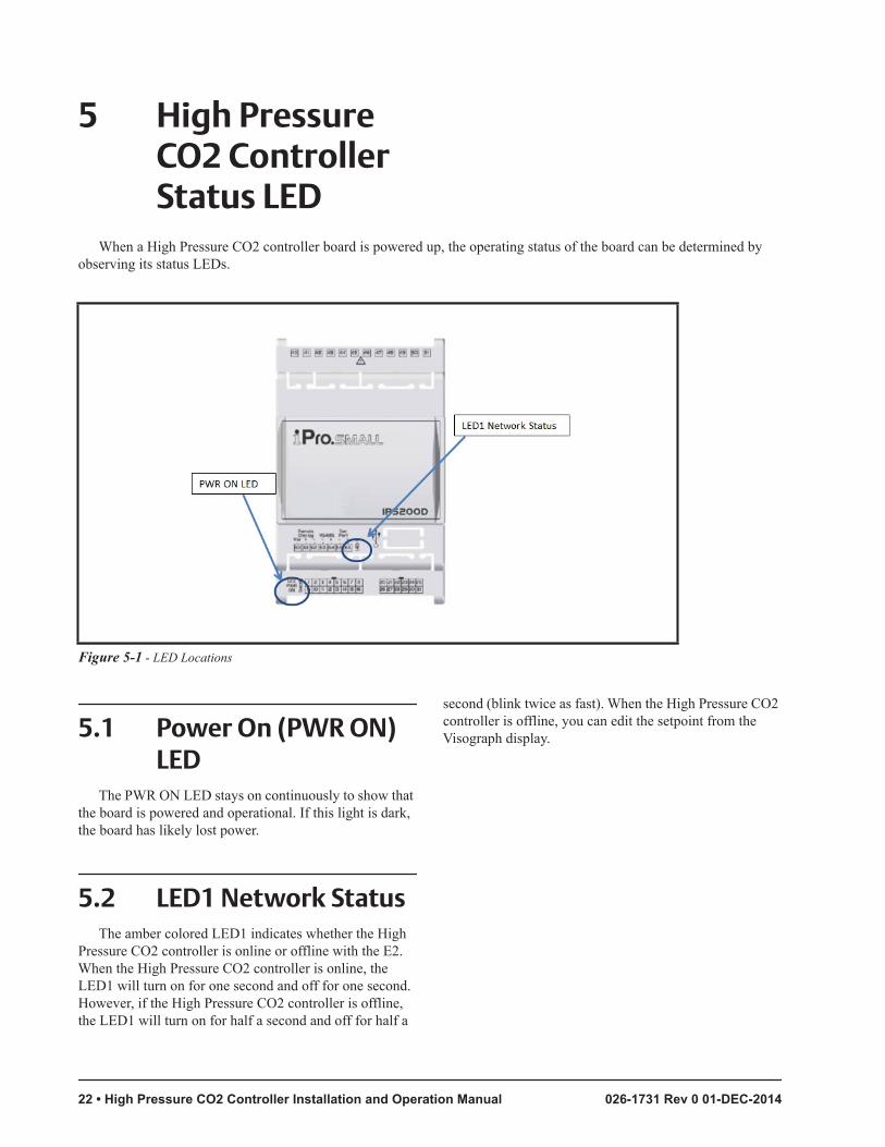
5 High Pressure CO2 Controller Status LED
When a High Pressure CO2 controller board is powered up, the operating status of the board can be determined by observing its status LEDs.
Figure 5-1 - LED Locations
5.1 Power On (PWR ON) LED
The PWR ON LED stays on continuously to show that the board is powered and operational. If this light is dark, the board has likely lost power.
5.2 LED1 Network StatusThe amber colored LED1 indicates whether the High
Pressure CO2 controller is online or offline with the E2. When the High Pressure CO2 controller is online, the LED1 will turn on for one second and off for one second. However, if the High Pressure CO2 controller is offline, the LED1 will turn on for half a second and off for half a
second (blink twice as fast). When the High Pressure CO2 controller is offline, you can edit the setpoint from the Visograph display.
22 • High Pressure CO2 Controller Installation and Operation Manual 026-1731 Rev 0 01-DEC-2014

6 Software Overview
The High Pressure CO2 controller application controls the operation of the high pressure valve and the bypass gas valve in a Booster Transcritical CO2 system. The controller will modulate both valves to maintain a setpoint.
Both the HPV and the BGV have safety modes. The safety control point in both valves is the receiver pressure. If the receiver pressure is higher than the high pressure setpoint, the HPV closes and the BGV opens. On the other hand, if the receiver pressure is too low, the HPV opens and the BGV closes.
6.1 High Pressure Valve Control
The high pressure valve (HPV) operates in two normal-control modes, in Subcritical and Transcriti-cal modes. The mode is defined by the control tem-perature. In the Subcritical mode, the valve will modulate to maintain a subcool setpoint using pres-sure and temperature control values being read from the gas cooler outlet to calculate subcool. In transcrit-ical mode, the HPV starts modulating to maintain a setpoint defined by an equation to achieve a virtual subcooling using only the pressure input as a control point.
6.1.1 HPV Subcritical Mode (Normal)
In Subcritical mode, when the control temperature (T1 or T2 is determined by digital input CTS) is below the HPV Mode setpoint minus Hysteresis, will control the HPV using PID and the calculated subcool value from the pressure and control temperature from the outlet of the gas cooler. The Subcritical inputs, outputs, setpoint and PID parameters are listed below.
Table 6-1 - Subcritical Inputs
Inputs Description Type
Temperature - 1(T1) Active Outlet Gas Cooler Temperature NTC Temperature
Temperature - 2 (T1) Active Bypass Gas Cooler Temperature NTC Temperature
Pressure - 1 (P1) Active Outlet Gas Cooler Pressure 0-5VDC only
Control Temp Selector (CTS) Enables T2 as Active Gas Cooler Temperature if present Digital Input
• 23

Table 6-2 - Subcritical Parameters
Subcritical Parameter Description Default Value
HPV Mode Setpoint Setpoint for Subcritical and Transcritical mode 31 DC (87 DF)
HPV Mode Hysteresis Control Temperature Hysteresis 3 DDC (5 DDF)
HPV Subcool Setpoint Subcool Setpoint in Subcritical Mode 2 DDC (3 DDF)
HPV RS-Temp Subcritical proportional band offset 0 DDC
HPV PB-Temp (P) Subcritical proportional band 16.7 DC (30DF)
HPV INC (I) Integral sampling time 140 Sec
HPV DDER (D) Derivative time 0 Sec
HPV Max Valve % Maximum valve % opening 100%
Table 6-3 - Outputs
Outputs Description Type
Valve % Output Valve Percentage Output
0-10VDC Only or LAN to
XEV20D
6.1.2 HPV Transcritical Mode (Normal)
In a booster Transcritical system, when the tempera-ture exceeds a certain value, there is no longer an accurate temperature to pressure relation. Because of this, the con-trol temperature of T1 or T2 (defined by digital CTS), will be the deciding factor of when the application will switches modes from subcritical to transcritical. If the con-trol temperature is above the HPV Mode setpoint, the application will be in transcritical mode. Once the control temperature is below the HPV Mode setpoint minus HPV Mode Hysteresis, the system reverts to subcritical mode.
In transcritical mode, the application will stop main-taining a subcool setpoint and start maintaining a setpoint value from an equation to achieve a virtual subcooling using only the pressure input as a control point. The con-trol temperature (T1 or T2) will still be used to as a refer-ence to calculate the setpoint equation. Below is an
estimation of what the setpoint will be for the given con-trol temperature readings.
24 • High Pressure CO2 Controller Installation and Operation Manual 026-1731 Rev 0 01-DEC-2014

Figure 6-1 - Setpoint Estimates for Temp Readings
In Transcritical mode, there is a separate PID running. To ensure there is a smooth transition between the subcrit-ical PID and the Transcritical PID, there is a linear-ratio transition algorithm between the two PID's output. This linear-ratio algorithm transition will keep the valve open and allow the Transcritical PID to ramp up and take over. The transition time is adjustable by the parameter "Trans_Time" if the valve tends to modulate too fast during the transition. By increasing the "Trans_Time" parameter, this will slow the transitions and allow less modulation. The same function will happen when transi-tioning from Transcritical mode to Subcritical mode as well.
The Transcritical inputs, outputs, setpoint and PID parameters are listed below.
Table 6-4 - Transcritical Inputs
Inputs Description Type
Temperature - 1(T1) Active Outlet Gas Cooler Temperature NTC Temperature
Temperature - 2 (T1) Active Bypass Gas Cooler Temperature NTC Temperature
Pressure - 1 (P1) Active Outlet Gas Cooler Pressure 0-5VDC only
Control Temp Selector (CTS) Enables T2 as Active Gas Cooler Temperature if present Digital Input
• 25

Table 6-5 - HPV Inputs
Transcritical Parameter Description Default Value
HPV Mode Setpoint Setpoint for Subcritical and Transcritical mode 31 DC (87 DF)
HPV Mode Hysteresis Control Temperature Hysteresis 3 DDC (5 DDF)
HPV Trans Setpoint Setpoint During Transcritical Mode From Equation
HPV RS-Press Transcritical proportional band offset 0 DDC
HPV PB-Press (P) Transcritical proportional band 22 BAR (330 PSI)
HPV INC (I) Integral sampling time 140 Sec
HPV DDER (D) Derivative time 0 Sec
HPV Max Valve % Maximum valve % opening 100%
Trans_Time Transition Time of the Sub and Trans PID 180 Sec
Note: The HVP INC, HPV DER, and HPV DDER values are shared in the PID settings for Subcritical and Transcriti-cal PID control.
Table 6-6 - Analog Outputs
Outputs Description Type
Valve % Output Valve Percentage Output 0-10VDC Only or LAN to XEV20D
6.1.3 HPV Heat ReclaimThe local Reclaim Setpoint Shift (HTR) or network (HTR) digital input determines if the application is in Heat
Reclaim. The priority of the input source will be determined as described in Section 4.1, Inputs Setup. If the Reclaim Setpoint Shift (HTR) digital input is true, the HTR S Set (Setpoint Shift-Subcritical) or HTR T Set (Setpoint Shift-Tran-scritical) value will be added to the corresponding setpoint mode for the High Pressure Valve (HPV). The input and parameters for setpoint added is listed below.
Table 6-7 - Heat Reclaim Digital Inputs
Inputs Description Type
Reclaim (HTR) Reclaim Setpoint Added 24VAC/DC
CAUTION! A separate 24V power supply must be used. Do not use the same power supply that is used to power the controller.
26 • High Pressure CO2 Controller Installation and Operation Manual 026-1731 Rev 0 01-DEC-2014

Table 6-8 - Analog Outputs
Heat Reclaim Parameter Description Type
Reclaim_Sub Reclaim Setpoint Shift HPV Subcritical Added 0 DDC
Reclaim_Trans Reclaim Setpoint Shift HPV Transcritical Added 0 DBAR
The Control Temp Selector (CTS) digital input is normally use if there is a gas cooler temperature sensor after a bypass valve to bypass the gas cooler if needed during heat reclaim. If the digital input is True, the subcool calculation for mode switching and Transcritical table being used by Temperature-1 (T1) will be switched to Temperature-2 (T2) as Con-trol temperature.
Table 6-9 - Analog Outputs
Inputs Description Type
Control Temp Selector (CTS)
Enables T2 as Active Gas Cooler Temperature if Present 24 VAC/DC
CAUTION! A separate 24V power supply must be used. Do not use the same power supply that is used to power the controller.
6.2 Bypass Gas Valve Control
The bypass gas valve (BGV) only operates in one nor-mal-control mode, which is to modulate the valve accord-ingly to maintain a pressure setpoint. The control reading is from the flash gas liquid receiver tank. If the BGV enters a safety mode, the PID will reset to begin safety operation.
Table 6-10 - BGV Input
Inputs Description Type
Pressure 2 - P2 Flash Gas Tank Liquid Receiver 0-5VDC only
• 27

Table 6-11 - BGV Parameters
BGV Parameter Description Default Value
BGV Setpoint Setpoint for Subcritical and Transcritical mode 35 BAR (510 PSI)
BGV RS Control Temperature Hysteresis 1.4 BAR (20 PSI)
BGV PB (P) Subcool Setpoint in Subcritical Mode 2.75 BAR (40 PSI)
BGV INC (I) Subcritical proportional band offset 100 Sec
BGV DDER (D) Subcritical proportional band 0 Sec
Table 6-12 - BGV Output
Outputs Description Type
Valve % Output Valve Percentage Output 0-10VDC Only or LAN to XEV20D
28 • High Pressure CO2 Controller Installation and Operation Manual 026-1731 Rev 0 01-DEC-2014

7 Safety Operation Parameters for High Pressure and Bypass Gas Valves
Refer to Section 7.3, Sensor Failure.
Table 7-1 - Input Safety Operation
Input Description
Pressure 2 Receiver Pressure
Hi PSI Set High Pressure Receiver Safety Setpoint
Hi Hy High Pressure Receiver Safety Setpoint Hysteresis
Lo PSI Set Low Pressure Receiver Safety Setpoint
Lo Hy Low Pressure Receiver Safety Setpoint Hysteresis
Close Rate Rate at which valve will close in failure mode
BGV % Open Fail % Open During P2 High Pressure sensor failure
HPV % Open Fail-SC % Open During P1 and Temp failure in subcritical mode
HPV % Open Fail-TC % Open During P1 failure in Transcritical mode
HPV % Fail Lo % Minimum Opening During Low Pressure alarm
Enable Close valves and disable application during emergency shutdown
7.1 Low Pressure Operation
The application determines Low Pressure mode if the receiver pressure is below the Low Pressure setpoint.
In Low Pressure mode, the application will open the HPV to a minimum user-defined percentage set by the HPV Fail Lo parameter and close the BGV.
7.1.1 Normal OperationOnce the receiver pressure rises above the Low Pres-
sure valve setpoint plus Hysteresis, the operation will be in normal mode.
7.2 High Pressure Operation
The application will determine High Pressure mode if the receiver pressure is above the High Pressure setpoint.
In High Pressure mode, the application will close the HPV and opens the BGV, the BGV will open to a user definable percentage set by the BGV % Open Fail parame-ter.
7.2.1 Normal OperationOnce the pressure falls below the high pressure valve
setpoint minus Hysteresis, the operation will be in normal mode.
In normal operation, both HPV and BGV will run off PID.
• 29

7.3 Sensor FailureIf a failure occurs on the pressure (P1) at the outlet of
the gas cooler, the application:
• Uses the back pressure from E2 (Section 4.1, High Pressure Controller Inputs).
• If no network backup pressure is available, set the HPV to a fixed opening according to the mode it is in (subcritical or transcritical). Pa-rameters for P1 failure (% Open Fail-SC and % Open Fail-TC) are in (Table 7-2).
If a failure occurs on the temperature (T1) at the outlet of the gas cooler, the application:
• Uses the back temperature from E2 (Section 4.1, Inputs Setup).
• In subcritical mode, if T1 fails, use T2 for con-trol. If T2 fails, switch to the failsafe % using close rate to adjust valve to HPV% Open Fail- SC.
• In transcritical mode, if T1 fails, use T2 for con-trol. If T2 fails, switch to the failsafe % using close rate to adjust valve to HPV% Open Fail- TC.
• If CTS is true in subcritical mode and T2 fails, switch to the failsafe % using close rate to ad-just valve to HPV% Open Fail-SC.
• If CTS is true in transcritical mode and T2 fails, switch to the failsafe % using close rate to ad-just valve to HPV% Open Fail-TC.
Table 7-2 - Condensing and Control Temperature Chart
Control Temp.
T Condensing
Control Temp.
T Condensing
°C °C °C °C
-3 5 9 17
-2 6 10 18
-1 7 11 19
0 8 12 20
1 9 13 21
2 10 14 22
3 11 15 23
4 12 16 24
5 13 17 25
6 14 18 26
7 15 19 27
8 16 20 28
If a failure occurs on the pressure at the receiver(P2), the application:
• Uses the back network pressure from E2, refer to Section 4.1, Inputs Setup.
• If no network backup pressure is available, set a user definable backup opening valve BGV % Open Fail.
7.4 Emergency Shutdown Enable Input
This input is used for emergency safety shutdown. If enable input signal is low, the application will close both the HPV and BGV first before disabling the application and generating an alarm. For normal operation, this digi-tal input has to be high for the application to be enabled. If the High Pressure CO2 controller is online with E2, both the physical digital input and the E2 network enable signal has to be high for the application to be enabled.
Control Temp.
T Condensing
Control Temp.
T Condensing
Table 7-2 - Condensing and Control Temperature Chart
30 • High Pressure CO2 Controller Installation and Operation Manual 026-1731 Rev 0 01-DEC-2014

8 Valve Calibration Feature
The calibration mode feature allows the user to set a time schedule to calibrate the HPV and/or BGV fully open 100 % or 0% closed to keep valve position accuracy during long period runtime. The calibration mode feature also has a monitoring parameter set by user to track when to initiate calibration if valve position is within a percent-age range to reduce system disruption.
In calibration mode, the High Pressure CO2 control-ler will send a signal of 100% to the XEV20D drive and a 10 volt analog output to calibrate open or a 0% to the XEV20D drive and a 0 volt analog output to either of the HPV and/or BGV. There is also a status display on both the Visograph and E2 to show if the calibration mode is initiated.
There are two parameters that will enable the valve calibration mode feature. The calibration parameters are:
1. Cal Time - is the hour of day the calibration mode will be initiated.
2. Cal Day - is the interval days of when the calibration mode will be initiated.
3. Cal T Frame - is the time period to monitor and wait for when the PID sets the valve percentage equal to or exceed the Cal Min Valve % before initiating calibration mode to minimized system disruption.
4. Cal Min Valve % - is the value for when the valve percentage has to equal to or exceed before executing cali-bration mode IF Cal T Frame value is greater than 0.
5. Direct - is the direction the calibration mode will be initialize the valve fully open or closed.
Cal Time and Cal Day values have to be greater than 0 to enable calibration mode.
Examples:
Table 8-1 - Cal Time and Day Values
HPV Cal Time 22
HPV Cal T Frame 1
HPV Cal Min Valve % 20
HPV Direct Closed
For my HPV valve, the calibration mode will take place every day because HPV CAL Day = 1 and it will start at 10:00PM since HPV CAL Time = 22. The calibra-tion mode then looks at the HPV Cal T Frame and since it is 1, the calibration mode will wait 1 hour for the valve percentage to equal HPV CAL Min Valve % = 20 or below to initiate the valve closed. If the valve percentage does not equal HPV CAL Min Valve % = 20 or below in 1 hour, then the calibration mode will initiate. If HPV CAL Min Valve % = 0, the calibration mode will skip this parameter and initiate every day at 10:00PM closed.
Figure 8-1 - Valve Calibration Parameters
• 31

9 AlarmsThe local display and the E2 have the ability to read
and display each alarm. Any sensor failure alarms will turn on the relay designated as the General Alarm. For the Shutdown alarm, this is true/active if the enable input is not high from either the physical digital input and/or E2 network if online with E2.
Table 9-1 - Alarm Designations
Alarm Local Network
Low Pressure Yes Yes
High Pressure Yes Yes
Sensor 1 Bad Yes Yes
Sensor 2 Bad Yes Yes
Sensor 3 Bad Yes Yes
Sensor 4 Bad Yes Yes
Sensor 5 Bad Yes Yes
Sensor 6 Bad Yes Yes
Enable/shutdown Yes Yes
32 • High Pressure CO2 Controller Installation and Operation Manual 026-1731 Rev 0 01-DEC-2014

10 VisographA Visograph is used as the local display. The screens
provide access for setting up and assigning all inputs, and outputs. In addition to the entire parameters’ configura-tion, the user can change the time and date, MODBUS address, baud rate (9600 or 19200), and update the Viso-graph with new screens if needed.
Note: Once the High Pressure CO2 controller is online with E2, you will only be able to make changes through E2 only. For some preference settings, please make changes on the Visograph before bringing the device online with E2.
10.1 Status ScreenIn the status screen, users will have visibility into the
operation of both HPV and BGV with their corresponding control values and parameters. This includes the HPV dual and failure/alarm operation modes. The status screen also provides values to show valve modulation. In addition, the application version is available on the first status screen.
10.1.1 Main Menu and Status Screens
Bootup Screen:
Figure 10-1 - Bootup Screen
Main Menu Screen:
Figure 10-2 - Main Menu Screen
Highlight Status to enter the Status screen.
Figure 10-3 - Status Screen
From the Status screen, you can select to view the General Status, HPV Status, BGV Status and Alarms screens. This screen also has the application version soft-ware. Highlight the status screen to view and press the T4 button for ENTER.
General Status Screen:
Figure 10-4 - General Status Screen
This screen gives you a general overview of the inputs and online status. To go back to the Status screen, press the
• 33

T1 button for EXIT.HPV Status Screen:
Figure 10-5 - HPV Status Screen
This screen gives you the HPV status of performance, setpoints, and control input values. To return to the Status screen, press the T1 button for EXIT.
BGV Status Screen:
Figure 10-6 - BGV Status Screen
This screen gives you the BGV status of performance, setpoints, and control input values. To return to the Status screen, press the T1 button for EXIT.
Alarm Status Screen:
Figure 10-7 - Alarm Status Screen
This screen gives you the alarm status values if the
alarm is true/active or false/not active. To return to the main Status screen, press the T1 button for EXIT.
10.2 Configuration Setup Screen
The Configuration setup screens are password pro-tected. In the Configuration screens, the user will have a menu listing of setting up the control valve configuration parameters, XEV20D valve settings, input + output con-figuration, and general configuration.
Under general configuration, it will have a menu with the MODBUS address, baud rate, screens update, time and date, Sensor type (Emerson Retail Solutions or Dixell), engineering units, pressure transducer settings, shutdown delay and the factory default reset. Note: Before connect-ing the High Pressure CO2 controller to E2, please make these preference changes since it will not be available through E2 once the device is online and configuration can only be made via the E2 once online.
The valve configuration screen will have all of the set-points parameters, PID settings, safeties, and calibration feature for the valves (HPV/BGV).
The input and output configuration screen will define the type of sensor function and the polarities of the digital inputs and outputs. It will also provide the inputs offset.
The XEV20D configuration screen is for setting up the valve specification if the XEV20D is chosen to drive the HPV valve and/or BGV valve.
10.2.1 Main Menu to Configuration Screens
To enter the Configuration Screens, you will need to be on the Main Menu to enter the password.
Figure 10-8 - Main Menu Screen
Main Menu screen. To enter the Configuration screen,
34 • High Pressure CO2 Controller Installation and Operation Manual 026-1731 Rev 0 01-DEC-2014

press T1 + T3 + T8 button together and hold it until you see the Configuration screen.
Configuration Screen:
Figure 10-9 - Configuration Screen
From this screen, you can select to configure the Gen-eral Config, Valve Config, IO Config and XEV20D Con-fig. Highlight the status screen to view and press T4 for ENTER.
10.2.2 General Configuration Screens
From the Configuration Screens, the user will have the ability to configure the MODBUS address, baud rate, screens up- date, time and date, temp Sensor type (Emer-son Retail Solutions or Dixell), engineering units, pressure transducer settings, shutdown delay and the factory default reset. Note: Before connecting the High Pressure CO2 Controller to E2, please make these preference changes since it will not be available through E2 once the device is online and configuration can only be made via E2 once online.
The General Config Screen:
Figure 10-10 - General Config Screen 1
Press T5 button (down arrow) to highlight the parame-ter you wish to change. Press T4 SET to edit the value.
Once the parameter is flashing, press the T3 button or T5 button to change value and press T4 SET again to submit the change. To see additional parameters in the General Config screen, press the T8 button (right arrow).
General Configuration Additional Screen:
Figure 10-11 - General Config Additional Screen
Press the T5 button (down arrow) to highlight the parameter you wish to change. Press T4 SET to edit the value. Once the parameter is flashing, press the T3 button or T5 button to change the value and press T4 SET again to submit the change. To go back to the other General Config screen, press the T3 button (left arrow) or press T1 button EXIT to exit back to the main Configuration screen.
10.2.3 Valve Configuration ScreensFrom the Configuration Screens, the user will have the
ability to configure the setpoints, PID settings, safety set-tings, and the calibration feature for the HPV and BGV.
Valve Configuration Screen:
Figure 10-12 - Valve Config Screen
Press the T5 button (down arrow) to high the parame-ter you wish to change. Press T4 SET to edit the value. Once the parameter is flashing, press the T3 button or T5 button to change value and press T4 SET again to submit change. To see additional parameters in the Valve Config screen, press T8 button (right arrow). Once in the addi-
• 35

tional Valve Config screen, you can press the T3 button (left arrow) to go back a screen or press the T1 button EXIT to exit back to the main Configuration screen.
Valve Configuration Additional Screen:
Figure 10-13 - Valve Config Additional Screen
Figure 10-14 - Valve Config Additional Screen
Valve Configuration Additional Screen:
Figure 10-15 - Valve Config Additional Screen
Figure 10-16 - Valve Config Additional Screen
Figure 10-17 - Valve Config Additional Screen
Figure 10-18 - Valve Config Additional Screen
10.2.4 I/O Configuration ScreensFrom the Configuration Screens, the user will have the
ability to configure the input and output, defined of the type of sensor function and the polarities of the digital inputs and outputs. It will also provide the inputs offset.
36 • High Pressure CO2 Controller Installation and Operation Manual 026-1731 Rev 0 01-DEC-2014

Figure 10-19 - IO Config Screen
IO Config Screen:
Press the T5 button (down arrow) to highlight the parameter you wish to change. Press T4 SET to edit the value. Once the parameter is flashing, press the T3 button or T5 button to change the value and press T4 SET again to submit change. To see additional parameters in the IO Config screen, press the T8 button (right arrow). Once in the additional Valve Config screen, you can press the T3 button (left arrow) to go back a screen or press the T1 but-ton EXIT to exit back to the main Configuration screen.
IO Configuration Additional Screen:
Figure 10-20 - IO Config Additional Screen
Figure 10-21 - IO Config Additional Screen
Figure 10-22 - IO Config Additional Screen
Figure 10-23 - IO Config Additional Screen
• 37

Figure 10-24 - IO Config Additional Screen
Figure 10-25 - IO Config Additional Screen
Figure 10-26 - IO Config Additional Screen
10.2.5 XEV20D Configuration Screens
From the Configuration Screens, the user will have the ability to configure the valve specification if the XEV20D is chosen to drive the HPV valve and/or BGV valve.
Figure 10-27 - XEV20D Config ScreenPress the T5 button (down arrow) to high the parame-
ter you wish to change. Press T4 SET to edit the value. Once the parameter is flashing, press the T3 button or T5 button to change value and press T4 SET again to submit change. To see additional parameters in the IO Config screen, press the T8 button (right arrow). Once in the addi-tional Valve Config screen, you can press the T3 button (left arrow) to go back a screen or press the T1 button EXIT to exit back to the main Configuration screen.
Figure 10-28 - XEV20D Config Additional Screen
10.3 Override ScreenIn the Override screen, users will have ability to over-
ride the operation of both HPV and BGV to a fix percent-age with a timer.
38 • High Pressure CO2 Controller Installation and Operation Manual 026-1731 Rev 0 01-DEC-2014

Figure 10-29 - Override Screen
• 39

11 High Pressure CO2 Controller Ranges and Default Setpoint Parameters
Setpoints Description Default Range Unit
HPV Mode Setpoint Setpoint for Subcritical and Transcritical mode switch 31 -3 to 42 DC
HPV Mode Hysteresis Control Temperature Hysteresis 2.8 0 to 20 DDC
HPV Subcool Setpoint Setpoint in Subcritical Mode 1.7 0 to 100 DDC
HTR S Set Reclaim Setpoint Shift-High Pressure Valve-Subcritical 0 0 to 30 DDC
HPV RS-Temp Subcritical band offset 0 0 to 100 DC
HPV PB-Temp Subcritical proportional band 16.7 0 to 100 DC
HPV Transcritical Setpoint Setpoint During Transcritical Mode From
Table-39.2 to 111 BAR
HTR T Set Reclaim Setpoint Shift-High Pressure Valve-Transcritical 0 0 to 30 DBAR
HPV RS-Press Transcritical band offset 0 0 to 500 BAR
HPV PB-Press Transcritical proportional band 12 0 to 500 BAR
HPV INC Integral sampling time 140 0 to 1000 Seconds
HPV DER Derivative sampling time 0 0 to 1000 Seconds
HPV DDER Derivative time 0 0 to 1000 Seconds
HPV Max % Maximum valve % open 100 0 to 100 %
BGV Setpoint Receiver pressure setpoint 34 0 to 500 BAR
BGV_PB BGV proportional band 2.75 0 to 500 BAR
BGV_RS BGV band offset 1.4 0 to 500 BAR
BGV_INC BGV integral sampling time 100 0 to 1000 Seconds
BGV_DER BGV derivative sampling time 0 0 to 1000 Seconds
BGV_DDER BGV derivative time 0 0 to 1000 Seconds
Hi PSI Set High pressure setpoint 43 0 to 1000 BAR
Hi Hy High pressure hysteresis 1 0 to 500 DBAR
Lo PSI Set Low pressure setpoint 30 0 to 500 BAR
Lo Hy Low Hysteresis 1 0 to 500 DBAR
Table 11-1 - High Pressure CO2 Controller Ranges and Default Setpoint Parameters
40 • High Pressure CO2 Controller Installation and Operation Manual 026-1731 Rev 0 01-DEC-2014

Close Rate Rate at which the HPV will close in safety mode 30 0 to 600 Seconds
HPV% Open Fail-SC Valve % open during Subcritical with sensor failure 0 0 to 100 %
HPV% Open Fail-TC Valve% open during Transcritical with sensor failure 0 0 to 100 %
HPV% Open Fail-Lo Valve% minimum opening during low pressure safety mode 15 0 to 100 %
BGV% Open Fail Valve% open during high pressure safety mode 0 0 to 100 %
TransMaxTime Transition time of the two Sub and Trans PID 180 30 to 600 Seconds
Setpoints Description Default Range Unit
Table 11-1 - High Pressure CO2 Controller Ranges and Default Setpoint Parameters
• 41

12 XEV20D Setup and Network Connection
The XEV20D is a stepper valve driver that can drive a bipolar stepper valve or unipolar stepper valve. It is a dummy voltage chopper constant current driver that will be controlled by the High Pressure CO2 controller through a LAN com-munication network. It can control the High Pressure Valve function and/or the Bypass Gas Valve function. The user has the option to use this driver or use the 0-10 voltage output from the High Pressure CO2 controller to another driver for controlling the valve. If this driver is preferred, please check the manufacturer valve technical specifications for the cur-rent ratings and verify if the XEV20D is capable of driving the valve. The XEV20D address will have to be set to 1 to communicate with the High Pressure CO2 controller.
CAUTION! GND is Common (-), not earth ground. Do not earth ground this device.
Figure 12-1- High Pressure CO2 Device Wiring and Network Connection
42 • High Pressure CO2 Controller Installation and Operation Manual 026-1731 Rev 0 01-DEC-2014

Figure 12-2 - High Pressure CO2 Device Wiring and Network Connection
• 43

13 Stepper Valve Actuator Quick Reference Guide XEV20D
13.1. General Warnings
Please read the following safety precautions and warnings before using the instructions in this section:
CAUTION!• This section is part of the product and should be kept near the controller for easy and quick
reference.• The controller should not be used for purposes
different from those described in this manual. It can-not be used as a safety device.
• Check the application limits before proceeding.
SAFETY PRECAUTIONS AND WARNINGS!• Check that the supply voltage is correct
before connecting the controller.• Do not expose to water or moisture: use the con-
troller only within the operating limits and avoid sud-den temperature changes with high atmospheric humidity to prevent condensation from forming.
• Warning! Disconnect all electrical connections before performing any kind of maintenance.
• Fit the probe where it is not accessible by the end user. The controller must not be opened.
• In case of failure or faulty operation, send the controller back to the distributor with a detailed description of the fault.
• Verify the maximum current that can be applied to each relay (see Section 13.8, XEV20D Technical Specifications).
• Ensure that the wires for probes, loads, and the power supply are separated and far enough from each other, without crossing or intertwining.
• In case of applications in industrial environ-ments, the use of main filters (mod. FT1) in parallel with inductive loads could be useful.
13.2 General DescriptionXEV20D is a stepper valve actuator intended either for
bipolar stepper valves or unipolar stepper valves. This device has been thought to be used with ISaGRAF® envi-ronment and with programmable devices or in combina-tion with instruments of i-CHILL 200CX series.
The maximum configuration of hardware is equipped with:
44 • High Pressure CO2 Controller Installation and Operation Manual 026-1731 Rev 0 01-DEC-2014

• 2 configurable valve outputs to drive bipolar or uni-polar valves
• Pb1/Pb2 configurable analog inputs: NTC/PTC/Pt1000
• Pb3/Pb4 configurable analog inputs: 4 to 20mA/0 to 5V/Pt1000
• CAN Bus serial line
• LAN to communicate with instrument of the same series or devices of i-CHILL200CX series
13.3 Absolute Maximum Power
XEV20D is able to drive a wide range of stepper valves. Indicated in the following table are the maximum values of current that the actuator can supply to the stepper wiring. Select the correct transformer depending on the application seeing the following table, for each kind of driving and functioning is reported to the transformer to use.
NOTE: The electrical power absorption of the valve can be unrelated to refrigeration power of the valve. Before using the actuator, read the technical manual of the valve supplied by
the manufacturer and check the maximum current used to drive the valve in order to verify that they are lower than those indicated below.
Figure 13-1 - Valve Max Power
13.4 Wiring Diagrams13.4.1 One Valve Configuration
Figure 13-2 - HPV Status Screen
13.4.2 Two Valve Configuration
Figure 13-3 - Two Valve Configuration
• 45
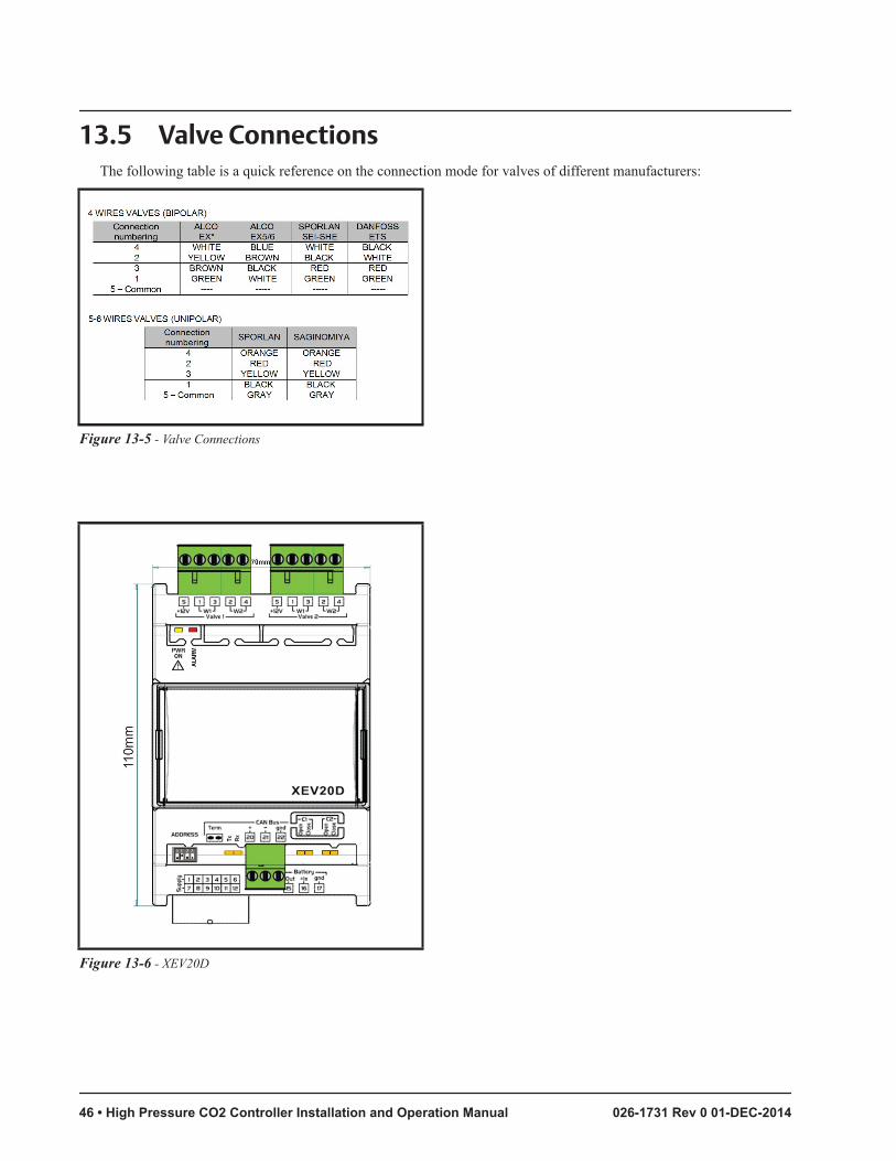
13.5 Valve ConnectionsThe following table is a quick reference on the connection mode for valves of different manufacturers:
Figure 13-5 - Valve Connections
Figure 13-6 - XEV20D
46 • High Pressure CO2 Controller Installation and Operation Manual 026-1731 Rev 0 01-DEC-2014

13.6 Serial Line - LAN BusThe device can communicate through LAN Bus serial line only when the address is set correctly. The addressing is
made through the dip-switch called Address as shown below. The XEV20D address will have to be set to 1 to communi-cate with the High Pressure CO2 controller.
Figure 13-7 - XEV22D
• 47

13.7 LED DescriptionsThe following table contains LED functions:
Figure 13-8 - LED Functions
13.8 XEV20D Technical Specifications
Case 4 DIN
Connectors Disconnectable Terminal Block 2.5 mm2 for valve outputs
and minifit connector for low voltage section
Power Supply 24VAC/DC Absorption: 40VA max.
Probe Inputs 2 configurable as NTC/PTC/Pt10002 configurable as NTC/PTC/Pt1000/4 to 20mA/to 5V
Valve Outputs Refer to the Valve Max Power Figure on page 44.
Serial Connection CAN Bus and LAN for iCHILL200CX
Data Storing On non-volatile memory (EEPROM).
Table 13-1 - XEV20D Technical Specifications
48 • High Pressure CO2 Controller Installation and Operation Manual 026-1731 Rev 0 01-DEC-2014

Kind of Action 1B; Pollution Grade: 2 Software Class: A
Rated Inpulsive Voltage
2500V; Overvoltage Category: II
Operating Temperature
-10 to 60°C (14°F to 140°F) Storage Temperature: -30 to 85°C (-22°F to 185°F)
Relative Humidity 20 to 85% (non-condensing)
Measuring and Regulation Range
PTC probe: -50 to150°C (-58°F to 302°F) NTC probe: -40 to110°C (-40°F to 230°F) Pt1000 probe: -50 to100°C (-58°F to 212°F)Pressure transducer: -1.0 to 50.0 Bar (-14.5 PSI to 725 PSI)
Resolution 0.1°C or 1°F; Accuracy@ 25°C: ±0.1°C ±1 digit
Case 4 DIN
Table 13-1 - XEV20D Technical Specifications
• 49

The contents of this publication are presented for informational purposes only and they are not to be construed as warranties or guarantees, express or implied, regarding the products or services described herein or their use or applicability. Emerson Climate Technologies Retail Solutions, Inc. and/or its affiliates (collectively “Emerson”), reserves the right to modify the designs or specifications of such products at any time without notice. Emerson does not assume responsibility for the selection, use or maintenance of any product. Responsibility for proper selection, use and maintenance of any product remains solely with the purchaser and end-user.
026-1731 01-DEC-2014 Emerson is a trademark of Emerson Electric Co. ©2014 Emerson Climate Technologies Retail Solutions, Inc. All rights reserved.