High Pressure Cleaners - Kranzle
40
High Pr High Pr High Pr High Pr High Pressur essur essur essur essure Cleaners e Cleaners e Cleaners e Cleaners e Cleaners Operating manual Operating manual Operating manual Operating manual Operating manual Read and conform Read and conform Read and conform Read and conform Read and conform safety instructions safety instructions safety instructions safety instructions safety instructions before use before use before use before use before use GB K K K K K
Transcript of High Pressure Cleaners - Kranzle

High PrHigh PrHigh PrHigh PrHigh Pressuressuressuressuressure Cleanerse Cleanerse Cleanerse Cleanerse Cleaners
Operating manualOperating manualOperating manualOperating manualOperating manual
Read and conform Read and conform Read and conform Read and conform Read and conform
safety instructions safety instructions safety instructions safety instructions safety instructions
before use before use before use before use before use
GB
KKKKK

Dear Customer
Permissible tolerance for figures ± 5 % in acc. with VDMA uniform sheet 24411
Technicalspecifications
Operating pressure,steplessly adjust.
Perm. overpressure
Water output
Hot water input
Suction height
High pressure hose
Electrical ratings
Connect. wattage input output
Weight
Dim. with mountedhandle in mm
Sound level acc.to45635with dirtkiller
Recoil at lance
Torque
Ord.-No
with dirtkiller
Kränzle115
10 - 115 bar
130 bar
at 1400 rpm10,3 l/min
max. 70 °C
2,5 m
10 m
230 V ; 50 Hz ;10 A
P1: 2,3 kWP2: 1,8 kW
22 kg
350 x 330 x 900
86 dB
88 dB
approx. 20 Nm
22 Nm
41.204
41.204 1
(Assumed lenght of lance: 0.9 m)
DescriptionDescriptionDescriptionDescriptionDescription
- facades- flagstones- terraces
- vehicles of all types- sheds- channels
- barrels and containers- machines etc.
Kränzle185
10 - 185 bar
200 bar
at 2800 rpm14 l/min
max. 60 °C
1 m
10 m
400 V ; 50 Hz ;8,7 A
P1: 4,6 kWP2: 4,0 kW
28 kg
350 x 330 x 900
93 dB
93 dB
approx. 32 Nm
28,8 Nm
41.203
41.203 1
We would like to congratulate you on your new high pressure cleaner with integratedundercarriage and integrated hose drum and to thank you for the purchase.
To ease your introduction to the use of the cleaner, we have provided the followingpages of explanations, tips and hints, which we ask you to read before using for thefirst time.
The equipment will assist you professionally in all cleaning tasks, e.g.:
Kränzle125
10 - 125 bar
140 bar
at 1400 rpm10,5 l/min
max. 70 °C
2,5 m
10 m
230 V ; 50 Hz ;12 A
P1: 2,8 kWP2: 2,0 kW
24 kg
350 x 330 x 900
87 dB
84 dB
approx. 22 Nm
24 Nm
41.200
41.200 1
Kränzle135
10 - 135 bar
150 bar
at 1400 rpm11,0 l/min
max. 70 °C
2,5 m
10 m
230 V ; 50 Hz ;13,5 A
P1: 3,1 kWP2: 2,3 kW
26 kg
350 x 330 x 900
89 dB
84 dB
approx. 25 Nm
26 Nm
41.201
41.201 1
Kränzle155
10 - 155 bar
170 bar
at 1400 rpm12 l/min
max. 70 °C
2,5 m
10 m
400 V ; 50 Hz ;6,3 A
P1: 3,3 kWP2: 2,6 kW
26 kg
350 x 330 x 900
88 dB
90 dB
approx. 27 Nm
24,3 Nm
41.202
41.202 1
2

3
9 8
2
Water
7
4 5
3
6
1 400 V
230 VConstruction
DescriptionDescriptionDescriptionDescriptionDescription
The KRÄNZLE 115 + 125 + 135 + 155 + 185 - high pressure cleaners aremobile machines. The design can be seen from the diagram.Item1 Water inlet connection with filter2 Suction hose with filter (special accessory) Order no. 15 038 33 High pressure pump4 Press. gauge with glycerin filling5 Unloader valve - safety valve
6 High pressure injector forcleaning agents
7 High pressure hose8 Spray gun9 Interch. lance with regulator
nozzle

Water and Cleaning SystemWater can be connected at mains pressure to the high pressure pump or itcan be sucked directly from a storage tank. The water is then forced underpressure by the high pressure pump to the lance. The high pressure jet isformed by the nozzle at the end of the lance.
Cleaning and caring agents can be mixed with the water by ahigh pressure injector.Environmental, refuse disposal and waterprotection regulations must be observed !
Lance with trigger gunThe machine can only be operated when the safety trigger is squeezed.
The machine can only be operated when the safety trigger is squeezed.When the lever is squeezed, the spray gun opens. The liquid is thenpumped to the nozzle. The spray pressure increases and quickly reachesthe selected operating pressure.
When the trigger is released, the trigger gun closes and any further sprayingof liquid from the lance is stopped.
The increase in pressure when the trigger gun is closed causes the unloadervalve-safety valve to open. The pump remains switched on and continues topump liquid through the pump at reduced pressure. When the trigger gun isopened, the unloader valve - safety valve closes and the pump ressumespressure spraying from the lance.
The trigger gun is a safety device. Repairs should only be per-formed by qualified persons. Should replacement parts berequired, use only components authorized by the manufacturer.
Unloader valve - safety valveThe unloader valve - safety valve protects the machine from a build p ofexcess pressure, and is designed not to permit an excess pressure to beselected for operation. The limit nut on the handle is sealed with a spraycoating
The operating pressure and spray rate can be steplessly adjusted by turningthe handle.
Replacements, repairs, new adjustments and sealing should onlybe performed by qualified persons.
DescriptionDescriptionDescriptionDescriptionDescription
4

5
Motor protection switchThe motor is protected from overload by a motor protection switch, whichautomatically cuts out the motor in the event of overload. However shouldthe switch trip frequently, the cause of the malfunction should be located andrectified (see page 6).
DescriptionDescriptionDescriptionDescriptionDescription
Replacements and inspection work should only be performed byqualified persons when the machine is disconnected fromthe power supply, i.e. pull out the plug from the electri-cal socket.
Setting up
LocationNeither set up and operate the machine in rooms where there isa risk of fire or explosion nor put it into puddles. Do not use themachine under water.
CAUTION !
Never use liquid containing solvents such as paint thinners,petrol, oil or similar liquid matter. Pay attention to the in-structions of the manufacturers of the cleaning agents.The seals in the machine are not resistant to solvents. The sprayof solvents is inflammable, explosive and poisonous.
CAUTION !
When running your high pressure cleaner with hot water of 70° Craised temperatures occur. Do not touch the machinewithout safety gloves!

Electrical connectionThe machine is supplied with an electrical power cord with plug.
The mains plug must be fitted to a standard grounded socketwith a 30mA residual current operated device. The socket mustbe protected with a 16A delay action fuse on the mains side.
KRÄNZLE 115, 125, and 135 - 230 Volt 50 HzKRÄNZLE 155 and 185 - 400 Volt 50 Hz (phase-sequence not
significant)
When using an extension cable, this must have an earthed leadwhich is properly connected to the socket. The conductors in theextension cable must have a minimum cross section of 1.5 mm².Plug connections must be of a spray-proof design, and may notbe located on a wet floor.(with extension cables of more than 10 m - 2.5 mm2 )
CAUTION !
The use of extension cables which are too long may lead to malfunctionsand start up difficulty.
When using a cable drum, always keep the cable wound as far as possible.
DescriptionDescriptionDescriptionDescriptionDescription
6

7
Brief operating instructionsare fitted to the machine. Numbers 1-6. When operating your high pressure cleaner pay attention that it is in a horizontal position.1. Connect the high pressure hose with spray gun and machine.2. Connect to suitable water supply.3. Flush the air from the pump (open and close the spray gun several times)4. Make the electrical connection - (KRÄNZLE 115, 125 + 135 230 Volt A.C., KRÄNZLE 155 and 185 400 Volt three-phase current).5. Switch on the machine with opened spray gun and commence cleaning.6. After completing the work, completely empty the pump (switch
the motor on for approximately 20 seconds without the suction and pressure hoses).
-Only use clean water ! Protect from frost !
CAUTION !Please pay attention to the regulations of your waterworks company. Inaccordance with DIN 1988, the machine may not be directly connected tothe public drinking water supply lines.
A brief connection however is permissible according to DVGW (GermanAssociation for Gas and Water Affairs) if a tube ventilator with check valve(Kränzle Order-No. 41.016 4) is built into the water supply.
Also indirect connection to the public drinking water supply lines is permissi-ble by way of free emission in accordance with DIN 1988, part 4; e.g. byusing a reservoir with a float valve.
Direct connection to a non-drinking water supply line is permissible.
High pressure hose and spray deviceThe high pressure hose and spraying device supplied with the machine aremade of high grade material, they are also optimized for the machine andmarked as required by the appropriate regulations.
If replacement parts are required, only such parts that are authorized by themanufacturer and which bear the markings required by theappropriate regulations may be used. The high pressure hoseand spray device must be connected in a pressure-tight man-ner. The high pressure hose may not be driven over, pulledexcessively, or twisted. The hose may under no circumstancesbe pulled over sharp edges, since otherwise the guarantee isautomatically void.
DescriptionDescriptionDescriptionDescriptionDescription

8
As to the recoil -see notice on page2 !
Apply the safety catch on thespray gun after each use, inorder to prevent uninten-tional spraying!
Always aim the underbodylance. Note when using anangled underbody lance,like for example lance No.41075, that there is acertain amount of torquein the recoil.(See also notice on page2 )
Safety notesSafety notesSafety notesSafety notesSafety notes

1. Spray lance with regulator and high pressure nozzle, flat spray 25045
2. Spray gun with insulated pistol grip and screw connection
3. KRÄNZLE - High pressure cleaners 115, 125, 135, 155 or 185
4. Crosstip screwdriver
Fixing screw for crank
5. Operating instructions
7. Water inlet components
8. Washing powder specimen
This is what you’ve purchased:This is what you’ve purchased:This is what you’ve purchased:This is what you’ve purchased:This is what you’ve purchased:
6. High pressure hose 10 m withsteel
reinforcementNW 6.
Filter already mounted
9

10
Put high Pressure cleanerinto upright position.Insert handle from aboveand fasten with 2 screwsfrom underneath.
Suspension for dirtkiller (specialaccessory)
Cable
High pressure hoseReceptaclefor spraygun
Receptaclefor lance
How to assemble and furnish your high pressure cleanerHow to assemble and furnish your high pressure cleanerHow to assemble and furnish your high pressure cleanerHow to assemble and furnish your high pressure cleanerHow to assemble and furnish your high pressure cleaner

Preparation for usePreparation for usePreparation for usePreparation for usePreparation for use
2. Connect the high pressure lance to the spray gun.
3. Unwind the high pressure hosewithout leaving kinks or "nooses"and connect it to the spray gun andpump. When using extension hoses,use max. 20 m high pressure hose,or 2 x 10 m with hose connectors.
High pressure hose connected from the machine to the lance.
Do not replace the plug !1. Put high pressure cleanerinto horizontal position!
THE HIGH PRESSURECLEANER IS ONLY TOBE OPERATED INHORIZONTALPOSITION !
11

4. The machine can be connected to apressurised water line with cold or70°C hot water (K 185 T up to 60°)
(see page 2).Ensure that the water supply isclean when sucking from externalsources. The hose cross section
must be at least 1/2” = 12.7 mm(free passage). Filter 1
must always be clean.
Please make surethat the filter 1 is cleanbefore using your highpressure cleaner.
CAUTION !
When running your high pressure cleaner with hot water of 60°or 70°C raised temperatures occur.Do not touch the pump without safety gloves!
Water
5. Maximum induction height 2.5 m (1m for K 185 ) see technical data on page 2
Preparation for usePreparation for usePreparation for usePreparation for usePreparation for use
4. The machine can be connected to apressurised water line with cold or70°C hot water (K 185 T up to 60°)
(see page 2).Ensure that the water supply isclean when sucking from externalsources. The hose cross section
must be at least 1/2” = 12.7 mm(free passage). Filter 1
must always be clean.
Please make surethat the filter 1 is cleanbefore using your highpressure cleaner.
CAUTION !
When running your high pressure cleaner with hot water of 60°or 70°C raised temperatures occur.Do not touch the pump without safety gloves!
Water
5. Maximum induction height 2.5 m (1m for K 185 ) see technical data on page 2
12

13
A mixing ratio of 3-5% isachieved when the Vario-Jet isfully turned on. pH value neutral7-9.
Turn on Vario-Jet to reach lowpressure !
This is accomplished by turning thehandwheel. The default setting ismaximum pressure.
Adjusting the pressure
Unwind HP-hose completely. Placechemical filter no. 5 in the reservoirwith the cleansing agent. Turn onVario-Jet No.4 to to enable theinjector to induct the cleansing agent.By turning back the Vario-Jet nozzle, thesupply of chemical is automatically cut off. Allow the cleans-ing agent to take effect and then remove with high pressure spray.
When using cleansingagents:
Note that you must alwayscomply with the instructionsprovided by the manufac-turer of the cleansing agent(e.g. instructions concerningsafety clothing) and thewater protection regulations!
To shut down the pump:1. Switch off the machine.2. Cut off the water supply.3. Open the spray gun briefly until the pressure is released.4. Apply the safety catch on the spray gun.5. Remove the water hose and spray gun.6. Drain the pump: switch on the motor for approx. 20 seconds.7. Pull the plug from the socket.8. Winter: store the pump in rooms above 0°C.9. Clean the water filter.
Preparation for usePreparation for usePreparation for usePreparation for usePreparation for use

Never direct thewater jet at themachine itself !
Never direct thewater jet at apower socket !
Never allowchildren to use thehigh pressurecleaner !
This is prohibitedThis is prohibitedThis is prohibitedThis is prohibitedThis is prohibited !
Never direct thewater jet at themachine itself !
Never direct thewater jet at apower socket !
Never allowchildren to use thehigh pressurecleaner !
14

15
Never direct thewater jet at peopleor animals !
Do not damage thepower cord or repairit incorrectly !
Never pull the highpressure hose if ithas formed kinks or“nooses”!Never pull the hoseover sharp edges !
This is prohibited !This is prohibited !This is prohibited !This is prohibited !This is prohibited !

Additional KRÄNZLE-accessories for ...Additional KRÄNZLE-accessories for ...Additional KRÄNZLE-accessories for ...Additional KRÄNZLE-accessories for ...Additional KRÄNZLE-accessories for ...
Rotary scrubbing brushOrder No. 41050 1
Drain and pipecleaning hose8 m - Order No. 4105115 m - Order No. 41058
Underbody lance, newOrder No. 41075 1
SandblasterOrder No. 41068 1
Flat brushOrder No. 41073
DirtkillerOrder No. 41072 5
Environmental, refuse disposal andwater protection regulations must beobserved when using the accessories!
16

... for further combination possibilities... for further combination possibilities... for further combination possibilities... for further combination possibilities... for further combination possibilities
Car cleaning, glass, caravan, boat etc.rotary washing brush with 40 cm exten-sion and ST 30 nipple M 22 x 1,5
Underbody cleaning of cars, trailers andequipment: lance 90 cm with high pressurenozzle and ST 30 nipple M 22 x 1,5.The lance must be aimed when spraying.
Cleaning cars and all smooth surfaces :brush with ST 30 nipple.
Rotary point sprayer for extreme soiling.Dirtkiller with 40 cm extension and ST 30nipple.
Cleaning pipes, channels and drains:pipe cleaning hose with KN nozzleand ST 30 nipple M 22 x 1,5
Blasting old paint, rust and facades: sand-blasting injector with suction lance, 3 mPVC hose and ST 30 nipple.
When sandblasting you mustwear protection clothes!Payattention to the instructionsof the manufacturer of theabrasive!
17

18
Then straighten a paper clip ...
and release the injector with an open-ended spanner
Remove the injectortogether with thespring and return valve.
and check thatit is clean.
Reconnect the hose, and you areready to continue
your work!
and replace thereturn valve.
The injector may be dirty and you should first remove the hose!
Now turn on the water andyou should get a powerfulstream of water
But if you onlyget a weak flow
Clean the injectorthoroughly from both sides
The pressure gauge shows a 10% higher pressure than the working pres
You only get a weak flow of water or no water at all!
Small repairs -Small repairs -Small repairs -Small repairs -Small repairs -

19
The nozzle is blocked!No water but the gauge shows full pressure !
- Do it yourself!
Rinse the hose through first.
You should now have apowerful stream of
water,
but if youonly get a fewdrops fromthe lance
remove the lance and cleanthe nozzle.
Using the flat spray lance youonly have to clean the
front nozzle.
Straighten a paperclip and clean the nozzle.Insert pointed object
into the hole and pullthe cap back!
Check visually whether thenozzle is clean.
Now it works as wellas before.

Pressure gauge does not show full pressure.
Water comes out in spurts.
If you do not use the high-pressure cleaner for some time the valves canstick
Straighten apaper clip...
When a valve is blocked, the gaugeshows littlepressure orno pressure at all,
or the highpressure
hose vibrates!
Open the valvewith a socket
wrench...
and remove thevalve screw, thevalve and theo-ring.
Replace the rubber o-ring.and remove the dirtfrom the valve - thevalve inside mustbe closed.
Retighten the valvescrew
...and repeaton all 6 valves.
Now it works aswell as before!
Nozzle dirty or sticky!Small repairs - Do it yourself!Small repairs - Do it yourself!Small repairs - Do it yourself!Small repairs - Do it yourself!Small repairs - Do it yourself!
The high-pressurehose vibrates.
20

TTTTTrigger gun with lancerigger gun with lancerigger gun with lancerigger gun with lancerigger gun with lance
No
De
sc
rip
tio
nQ
ty.
Ord
.-N
o
1H
andg
riff
mit
Ven
tilkö
rper
112
.165
2A
bdec
kung
sei
tlich
112
.166
3.1
Roh
rans
chlu
ßte
il R
1/4"
112
.125
3a+b
Mes
sing
hüls
e m
it Te
flons
itz1
12.1
274
O-R
ing
12
x 2
115
.005
15
Abd
ecku
ng u
nten
112
.167
6D
ruck
plat
te1
12.1
687
Abz
ug-H
ebel
112
.169
8M
essi
ng-S
chei
be1
12.1
359
O-R
ing
3,3
x 2
,41
12.1
3610
Sic
heru
ngsh
ebel
112
.170
11S
tift
3 x
171
12.1
7112
Kon
term
utte
r M
42
12.1
3813
Sch
raub
e 3
,9 x
9,5
412
.172
14S
T 3
0-N
ippe
l M22
x 1
,5 /
R 1
/4"
AG
113
.365
Sp
are
pa
rts
list
Gu
n w
ith
La
nc
e
No
De
sc
rip
tio
nQ
ty.
Ord
.-N
o
15R
ohr
kuns
tsto
ffum
sprit
zt b
ds.
R 1
/4"
AG
115
.004
216
Übe
rwur
fmut
ter
ST
30
M22
x 1
,5 I
G1
13.2
76 1
17A
ußen
-Sec
hska
nt-N
ippe
l R
1/4
" IG
113
.277
118
O-R
ing
9,3
x 2
,41
13.2
7319
ST
30-
Nip
pel
M 2
2 x
1,5
AG
/ M
12
x 1
113
.363
20R
ohr
400
lang
, bd
s. M
12 x
11
41.5
2721
Kol
bens
tang
e m
it K
olbe
n1
12.1
4322
Dru
ckfe
der
112
.145
23K
unst
stof
f-H
ülse
113
.202
24R
egel
düse
ohn
e H
ülse
143
.439
25S
pren
grin
g1
43.4
4128
Alu
min
ium
Dic
htrin
g6
13.2
7529
O-R
ing
6,0
x 3
,01
14.1
2130
HD
-Düs
e 25
045
126
.003
31D
üsen
halte
r1
26.0
04
Gu
n "
Pic
o"
with
ext
ensi
on4
1.0
53
1
La
nc
e w
ith r
egul
ator
and
43
.44
0hi
gh p
ress
ure
nozz
le f
lat
spra
y 25
045
Re
p.-
Kit
"P
ico
"1
2.1
58
cons
istin
g of
: 1x
Pos
ition
:3.
1, 3
a, 3
b, 4
, 8, 9
, 12,
21,
22
21

22
Complete assemblyComplete assemblyComplete assemblyComplete assemblyComplete assembly

223232323 23
KRÄNZLE 115 / 125 / 135 / 155 / 185KRÄNZLE 115 / 125 / 135 / 155 / 185KRÄNZLE 115 / 125 / 135 / 155 / 185KRÄNZLE 115 / 125 / 135 / 155 / 185KRÄNZLE 115 / 125 / 135 / 155 / 185
No
De
sc
rip
tio
nQ
ty.
Ord
.-N
o
1M
otor
WE
CH
SE
LST
RO
M f
ür K
115
143
.448
1M
otor
WE
CH
SE
LST
RO
M f
ür K
125
143
.400
1M
otor
WE
CH
SE
LST
RO
M f
ür K
135
143
.302
1M
otor
DR
EH
ST
RO
M f
ür K
155
143
.327
1M
otor
DR
EH
ST
RO
M f
ür K
185
143
.401
Mot
oren
jew
eils
kom
plet
t m
it Ö
lgeh
äuse
und
Lüfte
rrad
ohn
e S
chal
ter
2G
ehäu
sehä
lfte
rech
ts1
43.4
023
Hal
teru
ng K
onde
nsat
or1
43.4
034
Geh
äuse
hälft
e lin
ks K
115
143
.404
14.
1G
ehäu
sehä
lfte
links
K 1
251
43.4
04 2
4.2
Geh
äuse
hälft
e lin
ks K
135
143
.404
34.
3G
ehäu
sehä
lfte
links
K 1
551
43.4
04 4
4.4
Geh
äuse
hälft
e lin
ks K
185
143
.404
55
Gum
mid
ämpf
er2
43.4
056
Unt
ersc
hale
11
43.4
067
Unt
ersc
hale
21
43.4
078
Han
dgrif
f S
chal
e 1
143
.408
9H
andg
riff
Sch
ale
21
43.4
0910
Sch
lauc
hhal
ter
R (
rech
ts)
143
.410
11S
chla
uchh
alte
r L
(link
s)1
43.4
1112
Rad
243
.412
13R
adka
ppe
243
.413
14P
ICO
-Pis
tole
mit
Ver
läng
erun
g1
41.0
53 1
15S
chm
utzk
iller
045
mit
Lanz
e1
41.0
72 5
16R
egel
düse
mit
HD
-Düs
e 25
045
und
Lanz
e1
43.4
4017
Roh
r fü
r H
andg
riff
143
.414
18K
unst
stof
fsch
raub
e 3
,5 x
20
543
.415
19O
-Rin
g 9
,3 x
2,4
213
.273
20H
D-S
chla
uch
NW
6
10 m
21
0 ba
r1
43.4
1621
Che
mik
alie
nsau
gsch
lauc
h m
it F
ilter
115
.038
No
De
sc
rip
tio
nQ
ty.
Ord
.-N
o
22K
unst
stof
fsch
raub
e 4
,0 x
16
543
.417
23K
unst
stof
fsch
raub
e 5
,0 x
30
243
.418
24G
umm
idäm
pfer
443
.419
25K
unst
stof
fsch
raub
e 4
,0 x
60
243
.420
26S
chra
ube
M 6
x 1
24
43.4
2127
Kni
cksc
hutz
tülle
143
.422
28K
abel
mit
Ste
cker
(W
echs
elst
rom
)fü
r K
ränz
le 1
15 /
125
/ 135
141
.092
28.1
Kab
el m
it S
teck
er (
Dre
hstr
om)
für
Krä
nzle
155
/ 1
851
41.0
92 1
29K
unst
stof
fsch
raub
e 6
,0 x
30
243
.423
30S
tarlo
ck-K
appe
Dur
chm
esse
r 12
243
.424
31S
chra
ube
M 5
x 1
08
43.0
2132
Kun
stst
offs
chra
ube
243
.425
33S
chau
mst
offr
ohr
für
Kon
dens
ator
141
.418
34K
unst
stof
fsch
raub
e 5
,0 x
14
443
.426
35H
alte
büge
l2
43.4
2736
Bod
enbl
ech
mit
Mot
orac
hse
143
.428
37K
usts
toffs
chei
be 1
2,5
mm
243
.429
38K
unst
stof
fsch
raub
e 3
,5 x
88
43.4
3039
Kab
elkl
emm
e2
43.4
3140
Kun
stst
offs
chra
ube
5,0
x 8
02
43.4
3241
Kun
stst
offs
chra
ube
5,0
x 1
201
43.3
0942
Sch
alte
rble
nde
143
.433
43K
abel
führ
ung
243
.061
44K
abel
aufla
ge1
43.0
62
Sp
are
pa
rts
list
KR
ÄN
ZL
E 1
15
/ 1
25
/ 1
35
/ 1
55
/ 1
85
Co
mp
lete
asse
mb
ly

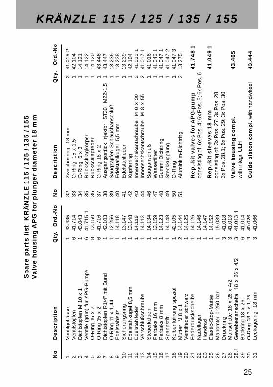
VVVVValve housing 18 mmalve housing 18 mmalve housing 18 mmalve housing 18 mmalve housing 18 mm
24
52524
No
De
sc
rip
tio
n Q
ty.
Ord
.-N
o
1V
entil
gehä
use
143
.435
2V
entil
stop
fen
641
.714
3D
icht
stop
fen
M 1
0 x
11
43.0
434
Ven
tile
(grü
n) f
ür A
PG
-Pum
pe6
41.7
15 1
5O
-Rin
g 16
x 2
813
.150
6O
-Rin
g 15
x 2
641
.716
7D
icht
stop
fen
R1/
4" m
it B
und
142
.103
8O
-Rin
g 11
x 1
,44
112
.256
9E
dels
tahl
sitz
114
.118
10S
iche
rung
srin
g1
13.1
4711
Ede
lsta
hlku
gel 8
,5 m
m1
13.1
4812
Ede
lsta
hlfe
der
114
.119
13V
ersc
hluß
schr
aube
114
.113
14S
teue
rkol
ben
114
.134
15P
arba
ks 1
6 m
m1
13.1
5916
Par
baks
8 m
m1
14.1
2317
Spa
nnst
ift1
14.1
4818
Kol
benf
ühru
ng s
pezi
al1
42.1
0519
Mut
ter
M 8
x 1
214
.144
20V
entil
fede
r sc
hwar
z1
14.1
2521
Fed
erdr
ucks
chei
be1
14.1
2622
Nad
ella
ger
114
.146
23H
andr
ad1
14.1
4725
Ela
stic
-Sto
p-M
utte
r1
14.1
5226
Man
omte
r 0-
250
bar
115
.039
27D
ruck
ring
341
.018
28M
ansc
hette
18
x 26
x 4
/23
41.0
1328
.1G
eweb
eman
sche
tte
18 x
26
x 4/
23
41.0
13 1
29B
ackr
ing
18 x
26
641
.014
30O
-Rin
g 28
,3 x
1,7
83
40.0
2631
Leck
ager
ing
18
mm
341
.066
No
De
sc
rip
tio
nQ
ty.
Ord
.-N
o
32Z
wis
chen
ring
18
mm
341
.015
233
O-R
ing
15
x 1,
51
42.1
0434
O-R
ing
6 x
31
14.1
2135
Rüc
ksch
lagk
örpe
r1
14.1
2236
Rüc
ksch
lagf
eder
114
.120
37O
-Rin
g 18
x 2
143
.446
38A
usga
ngss
tück
Inj
ekto
r S
T30
M
22x1
,51
43.4
4739
Sau
gzap
fen
Sch
lauc
hans
chlu
ß1
13.2
3640
Ede
lsta
hlku
gel
5,5
mm
113
.238
41E
dels
tahl
fede
r1
13.2
3942
Kup
ferr
ing
142
.104
43In
nens
echs
kant
schr
aube
M
8 x
30
241
.036
144
Inne
nsec
hska
ntsc
hrau
be
M 8
x 5
52
41.0
17 1
46S
auga
nsch
luß
141
.016
47W
asse
rfilt
er1
41.0
46 1
48G
umm
i D
icht
ring
141
.047
149
Ste
ckku
pplu
ng1
41.0
47 2
50O
-Rin
g1
41.0
47 3
51A
lum
iniu
m-D
icht
ring
213
.275
Rep.-kit
valv
es
for
AP
G-p
um
p41.7
48 1
cons
istin
g of
: 6x
Pos
. 4; 6
x P
os. 5
; 6x
Pos
. 6
Re
p.-k
it s
lee
ves
18
mm
41.0
49 1
cons
istin
g of
: 3x
Pos
. 27;
3x
Pos
. 28;
3x P
os. 2
8.1;
6x
Pos
. 29;
3x
Pos
. 30
Valv
e h
ousi
ng c
om
pl.
43.4
65
with
inte
gr. U
LH
Guid
e p
isto
n c
om
pl. w
ith h
andw
heel
43.4
44
Sp
are
pa
rts
list
KR
ÄN
ZL
E 1
15
/ 1
25
/ 1
35
/ 1
55
Va
lve
ho
usi
ng
AP
G fo
r p
lun
ge
r d
iam
ete
r 1
8 m
m
KRÄNZLE 115 / 125 / 135 / 155KRÄNZLE 115 / 125 / 135 / 155KRÄNZLE 115 / 125 / 135 / 155KRÄNZLE 115 / 125 / 135 / 155KRÄNZLE 115 / 125 / 135 / 155
25
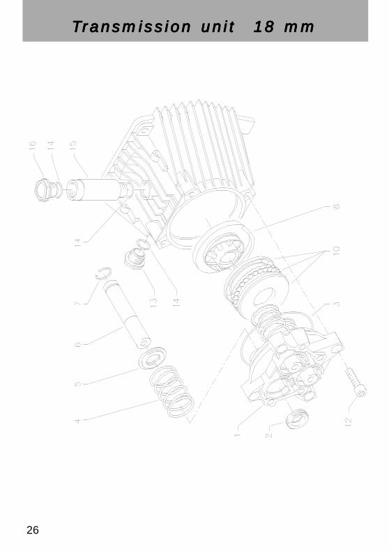
TTTTTransmission unit 18 mmransmission unit 18 mmransmission unit 18 mmransmission unit 18 mmransmission unit 18 mm
26

27
No
De
sc
rip
tio
nQ
ty.
Ord
.-N
o
1G
ehäu
sepl
atte
für 1
8 m
m P
lung
er1
41.0
20 2
2Ö
ldic
htun
g 18
x 2
8 x
73
41.0
313
O-R
ing
Vito
n 8
8 x
21
41.0
21 1
4P
lung
erfe
der
341
.033
5F
eder
druc
ksch
eibe
18
mm
341
.034
6P
lung
er 1
8 m
m3
41.0
32 1
7S
pren
grin
g 18
mm
341
.035
8Ta
umel
sche
ibe
11,0°
bie
Krä
nzle
115
Wec
hsel
stro
m1
41.0
28-1
1,0
8Ta
umel
sche
ibe
11,5°
bie
Krä
nzle
125
Wec
hsel
stro
m1
41.0
28-1
1,5
8Ta
umel
sche
ibe
12,0°
bie
Krä
nzle
135
Wec
hsel
stro
m1
41.0
28-1
2,0
8Ta
umel
sche
ibe
13,0°
bie
Krä
nzle
155
Dre
hstr
om1
41.0
28-1
3,0
bitte
Tau
mel
win
kel j
ewei
ls m
it an
gebe
n10
Axi
al-R
illen
kuge
llage
r 3-te
ilig
143
.486
12In
nens
echs
kant
schr
aube
M 8
x 3
04
41.0
36 1
13Ö
lsch
augl
as1
42.0
18 1
14O
-Rin
g 1
4 x
23
43.4
4515
Öle
infü
ll-S
tutz
en1
43.4
3816
Öl-V
ersc
hluß
schr
aube
Mes
sing
143
.437
1
Sp
are
pa
rts
list
KR
ÄN
ZL
E 1
15
/ 1
25
/ 1
35
/ 1
55
Tra
nsm
issi
on
un
it fo
r p
lun
ge
r d
iam
ete
r 1
8 m
m
KRÄNZLE 115 / 125 / 135 / 155KRÄNZLE 115 / 125 / 135 / 155KRÄNZLE 115 / 125 / 135 / 155KRÄNZLE 115 / 125 / 135 / 155KRÄNZLE 115 / 125 / 135 / 155

28
A. C. motorA. C. motorA. C. motorA. C. motorA. C. motor

2929999999999999999999999999999999999999999999999999999999999999999999999999999999999999999999999 29
No
De
sc
rip
tio
nQ
ty.
Ord
.-N
o
1Ö
lgeh
äuse
für A
P1
43.3
142
Mot
orge
häus
e m
it S
tato
r Wec
hsel
stro
mfü
r Krä
nzle
115
/ 12
51
43.4
00 9
2M
otor
gehä
use
mit
Sta
tor W
echs
elst
rom
für K
ränz
le 1
351
43.3
153
Rot
or m
it M
otor
wel
le W
echs
elst
rom
fü K
ränz
le 1
15 /
125
/ 135
143
.316
4P
aßfe
der 6
x 6
x 2
01
41.4
83 1
5M
otor
-Lag
er B
-Sei
te 6
205
- 2Z
143
.317
6M
otor
-Lag
er A
-Sei
te S
chul
terla
ger 7
304
BE
P1
41.0
278
Öld
icht
ung
25 x
35
x 7
141
.024
9Lü
fterr
ad B
G 9
01
43.3
1910
Lüfte
rhau
be B
G 9
01
43.3
2011
Fla
chdi
chtu
ng1
43.0
3012
Lüst
erkl
emm
e 2-
polig
143
.031
13S
chal
terg
ehäu
se B
G 9
01
43.3
2114
Sch
alte
r mit
13,5
A Ü
bers
trom
ausl
öser
141
.110
215
Kle
mm
rahm
en m
it S
chal
tera
bdic
htun
g1
41.1
10 5
16K
abel
vers
chra
ubun
g P
G 1
11
41.4
1917
Kab
elve
rsch
raub
ung
PG
9 (3
-teili
g)1
43.0
3418
Kon
dens
ator
70
µF1
43.3
2219
Kab
el m
it S
teck
er1
41.0
9220
Ble
chsc
hrau
be 3
,5 x
9,5
241
.088
21B
lech
schr
aube
2,9
x 1
61
43.0
3622
Sch
raub
e M
4 x
12
441
.489
23In
nens
echs
kant
schr
aube
M 6
x 3
04
43.0
3724
Erd
ungs
schr
aube
km
pl.
143
.038
25S
chra
ube
M 4
x 1
22
41.4
8926
Sch
elle
für L
üfte
rrad
mit
Sch
raub
en1
43.4
54
Sp
are
pa
rts
list
A
. C. m
oto
r fo
r K
RÄ
NZ
LE
11
5, 1
25
, 13
5
KRÄNZLE 115, 125, 135KRÄNZLE 115, 125, 135KRÄNZLE 115, 125, 135KRÄNZLE 115, 125, 135KRÄNZLE 115, 125, 135
30
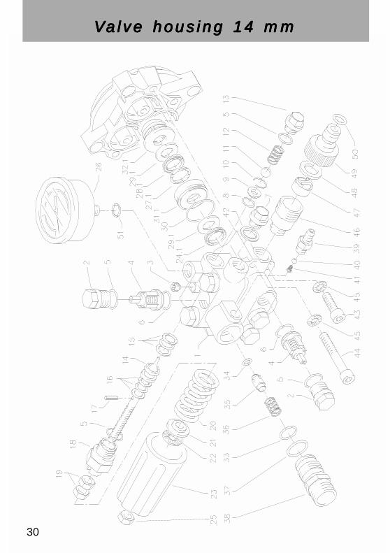
VVVVValve housing 14 mmalve housing 14 mmalve housing 14 mmalve housing 14 mmalve housing 14 mm

31
KRÄNZLE 185KRÄNZLE 185KRÄNZLE 185KRÄNZLE 185KRÄNZLE 185S
pa
re p
art
s li
st K
RÄ
NZ
LE
18
5V
alv
e h
ou
sin
g A
PG
fo
r p
lun
ge
r d
iam
ete
r 1
4 m
m
No
De
sc
rip
tio
nQ
ty.
Ord
.-N
o
1V
entil
gehä
use
AP
G m
it in
tegr
. UL
für 1
4 m
m P
lung
er-D
urch
mes
ser
143
.436
2V
entil
stop
fen
641
.714
3D
icht
stop
fen
M 1
0 x
11
43.0
434
Ven
tile
(rot
) für
AP
G-P
umpe
641
.715
5O
-Rin
g 16
x 2
813
.150
6O
-Rin
g 15
x 2
641
.716
7D
icht
stop
fen
R1/
4" m
it B
und
142
.103
8O
-Rin
g 11
x 1
,44
112
.256
9E
dels
tahl
sitz
114
.118
10S
iche
rung
srin
g1
13.1
4711
Ede
lsta
hlku
gel 8
,5 m
m1
13.1
4812
Ede
lsta
hlfe
der
114
.119
13V
ersc
hluß
schr
aube
114
.113
14S
teue
rkol
ben
114
.134
15P
arba
ks 1
6 m
m1
13.1
5916
Par
baks
8 m
m1
14.1
2317
Spa
nnst
ift1
14.1
4818
Kol
benf
ühru
ng s
pezi
al1
42.1
0519
Mut
ter
M 8
x 1
214
.144
20V
entil
fede
r sch
war
z1
14.1
2521
Fed
erdr
ucks
chei
be1
14.1
2622
Nad
ella
ger
114
.146
23H
andr
ad1
14.1
4724
.1M
ansc
hette
Gew
ebe
14 x
24
x 5/
2.5
341
.613
125
Ela
stic
-Sto
p-M
utte
r1
14.1
5226
Man
omte
r 0-2
50 b
ar1
15.0
3927
.1D
ruck
ring
341
.618
28.1
Man
sche
tte P
erbu
nan
14 x
24
x 5/
2.5
341
.613
29.1
Bac
krin
g 14
x 2
46
41.6
1430
O-R
ing
28,3
x 1
,78
340
.026
31.1
Leck
ager
ing
18
mm
341
.666
No
De
sc
rip
tio
nQ
ty.
Ord
.-N
o
32.1
Zw
isch
enrin
g 1
4 m
m3
41.6
15 2
33O
-Rin
g 1
5 x
1,5
142
.104
34O
-Rin
g 6
x 3
114
.121
35R
ücks
chla
gkör
per
114
.122
36R
ücks
chla
gfed
er1
14.1
2037
O-R
ing
18 x
21
43.4
4638
Aus
gang
sst.
Inje
ktor
ST
30 M
22x1
,51
43.4
4739
Sau
gzap
fen
Sch
lauc
hans
chlu
ß1
13.2
3640
Ede
lsta
hlku
gel
5,5
mm
113
.238
41E
dels
tahl
fede
r1
13.2
3942
Kup
ferr
ing
143
.455
43In
nens
echs
kant
schr
aube
M 8
x 3
02
41.0
36 1
44In
nens
echs
kant
schr
aube
M 8
x 5
52
41.0
17 1
45S
iche
rung
srin
g4
40.0
5446
Sau
gans
chlu
ß1
41.0
1647
Was
serfi
lter
141
.046
148
Gum
mi D
icht
ring
141
.047
149
Ste
ckku
pplu
ng1
41.0
47 2
50O
-Rin
g1
41.0
47 3
51A
lum
iniu
m-D
icht
ring
213
.275
Rep.-kit
valv
es
for
AP
G-p
um
p41.7
48
cons
istin
g of
: 6x
Pos
. 4; 6
x P
os. 5
; 6x
Pos
. 6
Re
p.-k
it s
lee
ves
14
mm
41.6
49 1
cons
istin
g of
: 3x
Pos
. 24.
1;3x
Pos
. 27.
1; 3
x P
os. 2
8.1;
6x
Pos
. 29.
1;3x
Pos
. 30;
3x
Pos
. 31.
1
Valv
e h
ousi
ng c
om
pl.
43.4
68
with
inte
gr. U
LH
Guid
e p
isto
n c
om
pl. w
ith h
andw
heel
43.4
44

32
TTTTTransmission unit 14 mmransmission unit 14 mmransmission unit 14 mmransmission unit 14 mmransmission unit 14 mm

3333 33
KRÄNZLE 185KRÄNZLE 185KRÄNZLE 185KRÄNZLE 185KRÄNZLE 185
Sp
are
pa
rts
list
KR
ÄN
ZL
E 1
85
Tra
nsm
isio
n u
nit
fo
r p
lun
ge
r d
iam
ete
r 1
4 m
m
No
De
sc
rip
tio
nQ
ty.
Ord
.-N
o
1G
ehäu
sepl
atte
für 1
4 m
m P
lung
er1
41.0
20 4
2Ö
ldic
htun
g 14
x 2
4 x
73
41.6
313
O-R
ing
Vito
n 8
8 x
21
41.0
21 1
4P
lung
erfe
der
341
.033
5F
eder
druc
ksch
eibe
14
mm
341
.634
6P
lung
er 1
4 m
m3
41.6
327
Spr
engr
ing
14 m
m3
41.6
358
Taum
elsc
heib
e 12
,5°
bie
Krä
nzle
185
Dre
hstr
om1
41.0
28-1
2,5
bitte
Tau
mel
win
kel m
it an
gebe
n10
Axi
al-R
illen
kuge
llage
r 3-te
ilig
143
.486
12In
nens
echs
kant
schr
aube
M 8
x 3
04
41.0
36 1
13Ö
lsch
augl
as1
42.0
18 1
14O
-Rin
g 1
4 x
23
43.4
4515
Öle
infü
ll-S
tutz
en1
43.4
3816
Öl-V
ersc
hluß
schr
aube
Mes
sing
143
.437
117
Sic
heru
ngsr
ing
440
.054

34
Three-phase current motorThree-phase current motorThree-phase current motorThree-phase current motorThree-phase current motor

35
Sp
are
pa
rts
list
T
hre
e-p
ha
se
cu
rre
nt
mo
tor
for
KR
ÄN
ZL
E 1
55
/ 1
85
No
De
sc
rip
tio
nQ
ty.
Ord
.-N
o
1Ö
lgeh
äuse
für A
P1
43.3
142
Mot
orge
häus
e m
it S
tato
r Dre
hstro
m1
43.3
24fü
r Krä
nzle
155
2.1
Mot
orge
häus
e m
it S
tato
r Dre
hstro
m1
43.4
01 9
für K
ränz
le 1
853
Rot
or m
it M
otor
wel
le1
43.3
25fü
r Krä
nzle
155
3.1
Rot
or m
it M
otor
wel
le1
43.4
01 8
für K
ränz
le 1
854
Paß
fede
r 6 x
6 x
20
141
.483
15
Mot
or-L
ager
B-S
eite
620
5 - 2
Z1
43.3
176
Mot
or-L
ager
A-S
eite
Sch
ulte
rlage
r 730
4 B
EP
141
.027
8Ö
ldic
htun
g 25
x 3
5 x
71
41.0
249
Lüfte
rrad
BG
90
143
.319
10Lü
fterh
aube
BG
90
143
.320
11F
lach
dich
tung
143
.030
13S
chal
terg
ehäu
se B
G 9
0 D
rehs
trom
143
.452
14S
chal
ter (
Am
azon
as) 8
A f
ür K
155
143
.450
14.1
Sch
alte
r (A
maz
onas
) 11
A f
ür K
185
143
.451
15K
lem
mra
hmen
mit
Sch
alte
rabd
icht
ung
143
.453
17K
abel
vers
chra
ubun
g P
G 1
3,5
140
.539
19K
abel
mit
Ste
cker
Dre
hstr
om1
41.0
92 1
20B
lech
schr
aube
3,5
x 9
,52
41.0
8822
Sch
raub
e M
4 x
12
441
.489
23In
nens
echs
kant
schr
aube
M 6
x 3
04
43.0
3724
Erd
ungs
schr
aube
km
pl.
143
.038
25S
chra
ube
M 4
x 1
22
41.4
8926
She
lle fü
r Lüf
terr
ad m
it S
chra
uben
143
.454
KRÄNZLE 155KRÄNZLE 155KRÄNZLE 155KRÄNZLE 155KRÄNZLE 155 / 185 / 185 / 185 / 185 / 185
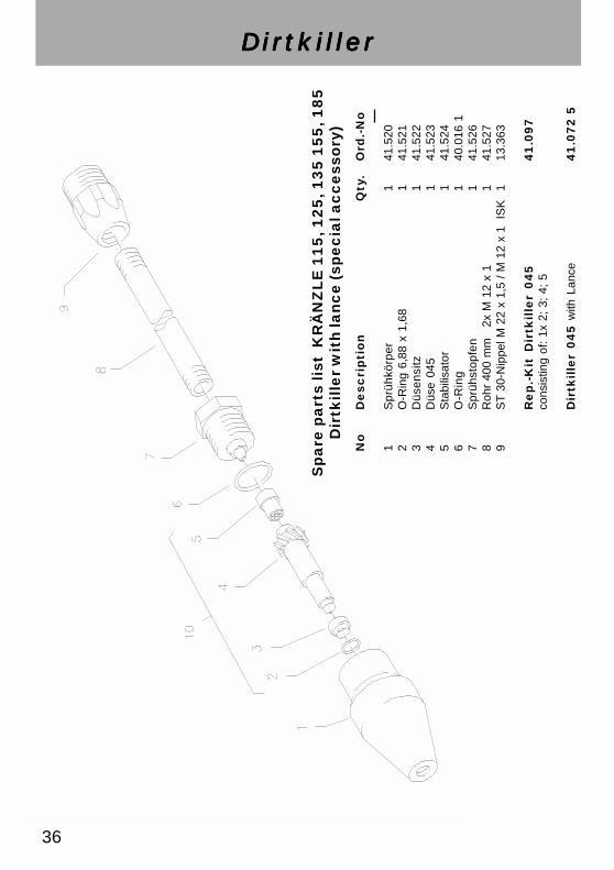
No
De
sc
rip
tio
nQ
ty.
Ord
.-N
o
1S
prüh
körp
er1
41.5
202
O-R
ing
6,88
x 1
,68
141
.521
3D
üsen
sitz
141
.522
4D
üse
045
141
.523
5S
tabi
lisat
or1
41.5
246
O-R
ing
140
.016
17
Spr
ühst
opfe
n1
41.5
268
Roh
r 40
0 m
m
2x
M 1
2 x
11
41.5
279
ST
30-
Nip
pel M
22
x 1,
5 / M
12
x 1
ISK
113
.363
Re
p.-
Kit
Dir
tkil
ler
04
54
1.0
97
cons
istin
g of
: 1x
2;
3; 4
; 5
Dir
tkil
ler
04
5 w
ith L
ance
41
.07
2 5
Sp
are
pa
rts
list
KR
ÄN
ZL
E 1
15
, 12
5, 1
35
15
5, 1
85
Dir
tkille
r w
ith
lan
ce
(sp
ec
ial a
cc
ess
ory
)
DirtkillerDirtkillerDirtkillerDirtkillerDirtkiller
36

37
Terminal strip
Weber-Unimat WT 22 - 55113,5A excess current release
Motor-Stator
Switch Weber - Amazonas 8 A for K15511 A for K185
KRÄNZLE 155 and 185 400 Volt / 50 Hz
Mot
or w
ith te
rmin
al b
ox
KRÄNZLE 115, 125, 135 230 Volt / 50 Hz
Wiring diagramWiring diagramWiring diagramWiring diagramWiring diagram
70 µF braun = brownblau = blueschw = blackrt = redge = yellowgn = greenws = white

38
InspectionsThe machine must be inspected according to the “Guidelines for LiquidSpray Devices” at least once every 12 months by a qualified person, toensure that continued safe operation is guarateed. The results of the inspec-tion are to be recorded in writing. This may be done in any form.
Accident preventionThe machine is designed for accidents to be impossible if used correctly.The operator is to be notified of the risk of injury from hot machine parts andthe high pressure water jet. The “Guidelines for Liquid Spray Devices” mustbe complied with. (see page 14 and 15)
Check the oil level at the oil sight glass prior to each use.(Ensure horizontal position!)
Oil change:The oil of your high pressure pump should be changed after approx. 40hours of operation, or no later than when it takes on a grey or whitish colour.To change the oil, remove the two combination screws on the base-plate atthe bottom, take off the base-plate and pull out the oil drainage hose. Putthe hose over a container and take off the closure cap. Put the pump intohorizontal position to drain off the oil. The oil must be caught in a containerand disposed of in a responsible, legal manner.New oil: 0.3 l - Motor oil: W 15/40
GuaranteeThe guarantee period is 24 months according to VDMA.
The guarantee is void if changes are made to the safety devices or if themachine is used at excess temperatures or speeds. The guarantee is alsovoid if the machine is used with a voltage below the required rating, with lessthan the required amount of water, with dirty water and external damage tothe pressure gauge, nozzle, high pressure hose and spray device.
This guarantee is not applicable for spare parts.
Our operating instructions must be complied with.
General rulesGeneral rulesGeneral rulesGeneral rulesGeneral rules

39
I. Kränzle GmbHElpke 97 . 33605 Bielefeld
Herewith we K 115 - K 185declare that
complies with the following 91/368 EEC Ann. I Nr. 1provisions applying to it 79/113 EEC 81/1051 EEC
Applied EN 292 T 1 and T 2harmonized standards EN 60 204 T 1in particular EN 50 082-2
EN 61 000 3-2 3-3
Applied national technical DIN VDE 0700 Part 265standards and specificationsin particular
Notified body 1) within the TÜV Hannovermeaning of Annex VII
engaged for 2)
- safe keeping of the file as defined by Annex VI- verification of correct application of harmonized standards and certification of adequacy of the file as defined by Annex VI- EC type-examination (EC type-examination certificate No. ...)
Bielefeld, 10.10.97
EC declaration of conformityas defined by machinery directive 89/392/EEC Annex II A
and the EC low-voltage directive 73/23 EECand the EC-EWV directive 89/336
HochdruckreinigerHigh-pressure-cleaners
Nettoyeurs à Haute Pression
(Superintendent)

Reprint only allowed with the authorization of
As of date of 10. 05. 2001