High Performance & Powerful Servo Drives for General Purpose · 2016-10-18 · High Performance &...
36
CSD7 Series High Performance & Powerful Servo Drives for General Purpose Provide two Kinds of Models • EtherCAT Network type • Pulse/Analog command type
Transcript of High Performance & Powerful Servo Drives for General Purpose · 2016-10-18 · High Performance &...

CSD7 Series
High Performance & Powerful Servo Drives
for General Purpose
Provide two Kinds of Models • EtherCAT Network type • Pulse/Analog command type

2 I CSD7 Series
CSD7 Series is the Servo Drive that has been developed based on the technical skills through 30 years' experience, and represents Korean servo drive. It provides smaller, stronger and more comfortable functions for our customers' systems.
CSD7Series
Smallest footprint, built-in Power, Servo Drive with high precision control
CSD7 Series
• EtherCAT Network type • Pulse/Analog command type
After On-line vibration suppression
Before vibration suppression
• CSD7 Series has a 23bit Encoder, so its motion profi le is high-resolution and smooth with fast position settling time. Vibration/noise has been improved as well for system stability.
Provide high resolution motor with 23bit Encoder
Old Motor
Vibration reduction“
”
• Enhanced Velocity Bandwidth : Up to 2kHz 1)
• H/W based current controller with minimized delay and enhanced current detection circuit.
• Real Time Vibration Suppression Function (Adaptive Notch Filter)
• 3rd Party Linear Motor support 2)
• Off ering index function in standard model
• Supporting 2 channels of high-speed Registration input
• Full Closed Loop Control 2)
Off ering improved basic functions
1) Result of our evaluation criteria.2) Full Closed Loop control will be released in 2016.
New Motor
CSD7 Series I 3
Reliable & Smart
Reliable & Smart · Global brand with the highest quality and performance.
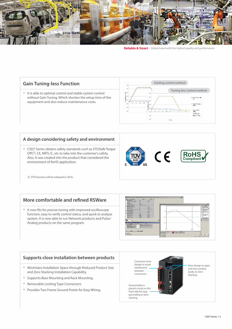
• It is able to optimal control and stable system control without Gain Tuning. Which shorten the setup time of the equipment and also reduce maintenance costs.
Gain Tuning-less Function Existing control method
Tuning-less control method
• Minimizes Installation Space through Reduced Product Size and Zero Stacking Installation Capability.
• Supports Base Mounting and Rack Mounting.
• Removable Locking Type Connectors
• Provides Two Frame Ground Points for Easy Wiring.
Supports close installation between products
Door design to open and shut window easily on Zero Stacking
Connector lever design to avoid interference between connectors
Ground plate is placed crossly on the front side for easy grounding on zero stacking
• It now fi ts for precise tuning with improved oscilloscope function, easy to verify control status, and quick to analyze system. It is now able to run Network products and Pulse/Analog products on the same program.
More comfortable and refi ned RSWare
• CSD7 Series obtains safety standards such as STO(Safe Torque Off )3), CE, NRTL/C, etc to take into the customer's safety. Also, it was created into the product that considered the environment of RoHS application.
A design considering safety and environment
3) STO function will be released in 2016.

4 I CSD7 Series
• It is now possible to reduce mechanical position error because rotary motor is used for speed/torque control and linear scale is used for position control.
Full Closed Loop Control For Velocity/ Torque control
For position control
RS 485,Modbus-RTU
Select 64 positions according to I/O
combination
Index function (Pulse/Analog command type)
EtherCAT CSD7
EtherNet-based real time motion network
Reliable & Smart · Global brand with the highest quality and performance.
• Through a simple programming, you can confi gure the system even without expensive controller. For example, it is able to operate the servo drive by choosing several I/Os or serial communication. Also it can implement cost eff ective system with low cost.
• Trapezoid, 5-Curve Acceleration
• High speed position registration function
• Control with Absolute position, Relative position
• 64 Point(I/O control), 128 Point(Modbus control) • Support Homing function • 32 axis controls are available through the Modbus communication
• Support application of EtherCAT CoE communication system and CiA402 drive profi le functions.
• Enable to connect with the host controller which support EtherCAT CoE, CiA402 Profi le
• Real-time motion control applied to the communication speed of 100Mbps
• Apply RJ45 type of Connector, use of STP Cable which is higher than CAT5(Category 5), Up to 100m between nodes

CSD7 Series I 5
Reliable & Smart
EtherCAT I/O Module
EtherNet-based real time motion control
Pulse/Analog Servo
EtherCAT CSD7
PCI express
EtherCAT I/O Module
MMC-EtherCAT Function Module
1)
1) Max distance between nodes is 100m.
CSD7 Series Product Composition
Pulse/Analog model
You can compose a real time EtherNet-based system at a lowest cost using various EtherCAT products, so that we offer EtherCAT solution together with MMC-EtherCAT Series, PC-based master. Choose from a wide range of choices not only including Pulse/Analog servo drive, but also networks.
EtherCAT model
There are two types of CSD7 series. (Pulse/Analog model, EtherCAT model)
MMC-EtherCAT Master

Drive and Motor Selection
Servo Drive Model Code Format
SC D 7 - 0 1
Rated Output(W)
010204081015253550
100W200W400W800W1kW
1.5kW2.5kW3.5kW5.0kW
B
Input Voltage(Vac)
B 220V
X
Drive Type
X Pulse / Analog
F
Option
Blank Standard ModelF Advanced Model
1
Design Order
1 Ver.1
N EtherCAT
Drive Series
CSD7 Series
Servo Motor Model Code Format
C S M T - 0 1 B R 1 A T 3
Motor Type
3 Key Type
Motor Shaft Specifi cation
A5010204060810152025304050
50W100W200W400W600W750W1kW
1.5kW2kW
2.5kW3kW4kW5kW
Rated Output(W)
NTBTSTTT
NoneBrake
Oil SealOil Seal, Brake
Option
RQT
17bit Incremental17bit Absolute
23bit Inc/Abs common
Encoder Form
B AC 220V
Input Voltage(Vac)
13
LBY TypeSBY Type
Encoder Type
N
CSMT SeriesCSMR SeriesCSMA SeriesCSMS SeriesCSMD SeriesCSMH Series
50~1kW
50~400W
50~750W
1~5kW
0.75~5kW
0.5~5kW
Available Motor Series
Motor Series ItemsRated
Output(W)
Rated Speed/
Max. Speed (rpm)
Motor
TypeEncoder
Protection
DegreeInertia
CSMA 50W~750W 3000/6000 (100W or less )3000/5000 (200W or more)
Cylinder
23bit serial
Abs./IncIP 67
Ultra low inertia
CSMT 50W~1kW
3000/5000
17bit serial
Abs./Inc
IP 65
CSMS 1kW~5kW
23bit serial
Abs./Inc
Low inertia
CSMD 750W~5kW
2000/3000
Middle inertia
CSMH 500W~5kW High inertia
6 I CSD7 Series
Reliable & Smart

CSD7 Series I 7
Reliable & Smart
CSD7 Series Specifications Common Specifi cations
Item Catalog No. 01B**1 02B**1 04B**1 08B**1 10B**1 15B**1 25B**1 35B**1 50B**1
OutputRated Current [Arms] 1.1 1.8 3.3 6.2 8.0 11.0 16.0 22.0 32.1
Maximum Current [Arms] 3.3 5.4 9.9 18.6 24.0 33.0 48.0 66.0 96.3
Main Power
Supply
Voltage RangeSingle-phase AC 200 ~ 230Vrms, +10%, -15%, 50/60Hz
3-phase AC 200 ~ 230 Vrms, +10%,-15%, 50/60Hz For 800w, single-phase can be used by changing parameter
Input Current [Arms] 1.1 2.1 4.0 5.5/7.8 7.7 11.1 15.4 20.7 33.8
Control Power supply Single-phase AC 200 ~ 230 Vrms, +10%, -15%, 50/60Hz
Encoder, Auxiliary Encoder 17 & 23 Bit Serial Absolute/Incremental, 21Bit Biss
Internal Regenerative Resistor - - 50Ω/30W 30Ω/100W 12Ω/150W 8Ω/250W
Dynamic Brake Provide Built-in Circuit that shorts two phase(U,W) of motor Support built-in circuit, 3-phase(U,V,W) the short-circuited via a resistor of 0.5Ω/100W
Communication
function USB Connect to PC to use serial communication. RSWare should be used through this port.
Environment
Operating Temperature/
Humidity0℃ ~ 50℃/90% RH or below (Non-condensing)
Storage Temperature/
Humidity-20℃ ~ 85℃/90% RH or below (Non-condensing)
Vibration/Shock Vibration : 2G or below, Shock : 15G or below (1G = Gravity Acceleration 9.8m/s2)
IP Class/Pollution Level IP20 / Pollution Class 2
Allowed Altitude Max. 1000m above sea level
Protective FunctionOver Current, Motor Overload, Drive Overload, Regenerative Overload, Over Voltage, Low Voltage, Over Speed, Over Heat, CPU Fault, Encoder Fault, Communication Fault, IPM Fault, Abnormal Motor Speed Setting, Over Position Error, Input Voltage Phase Loss, Abormal Motor Wiring, etc.
Safety FunctionFunctions Available STO(Safe Torque Off , IEC/EN 61800-5-2), Provide Additional Connector
Standards Applied IEC/EN 61508 SIL2, EN ISO 13849-1 PL d
Certifi cation CE Standard LVD:EN61800-5-1:2007, EMC:EN61800-3:2004+A1:2012
NRTL/C standard UL508C:2013, CSA C22.2 No.14:2013
KC KN 61800-3:2014
Cooling method Fan Cooling
InstallationMounting Method Base Mounted (Standard), Rack Mounted(Need Optional Mechanical Parts) Base Mounted
Zero Stacking It can be mounted without space between products.
Pulse/Analog Model
Item Catalog No. 01BX(F)1 02BX(F)1 04BX(F)1 08BX(F)1 10BX(F)1 15BX(F)1 25BX(F)1 35BX(F)1 50BX(F)1
Communication
function USB (RS-485) Support 1: N Multi-Drop function and 32-axis operation; set the axis number by a parameter
I/O Spec.
Encoder Output A, B and Z pulse output, Line Driver output, Division ratio: N/M (N,M≤32768); Absolute position can be sent by serial data.
Digital InputFunction allocable 8 points; fi xed 1 point (emergency stop); input detection time: 6ms to 8ms
High speed allocable 2 points: function allocation allowed, position registration, input detection time: 5us or under
Output Function allocable 6 points, Fixed 2 points(Encoder Z-pulse, Servo fault display)
Position Control
Position Command Type CCW+CW pulse train, Sign+Pulse train, A+B pulse train (90˚phase diff erence between A and B)
Command Input Circuit Line Driver(5V), Open Collector (5V external resistor required)
Maximum Input
Frequency 4Mpps (Line Driver), 250Kpps (Open Collector)
Electronic Gear Ratio 3 sets of electronic gears provided
Feedforward
Compensation0 - 100% (Setting Resolution : 1%)
Velocity control
Command Type Analog Velocity Command, Internal Speed Command
Range of Control Analog Velocity Command (1 : 2000), Internal Speed Command (1 : 5000)
Velocity Variation RatedInput voltage variation (AC 170 ~ 253 Vrms AC): 0%, Load variation (0-100%): ±0.01% Max, Temperature variation (25℃±25℃):±0.1%
Acceleration/Deceleration
Setting Range 0 - 60 sec
Analog Speed Input DC 0V - ± 10V (For initial value, 6V is set as a rated speed.)
Torque Control
Command Type Analog Torque Command
Analog Torque Input DC 0V - ±10V (For initial value, 3V is set as a rated torque.)
Control Accuracy
(Reproducibility)± 1%
Built-in Operator 1. Six 7-segment LED; 2. Four buttons for Parameter setting
Analog Monitor Function 2 Points, DC ± 10V, max voltage : ± 10mA, 12Bit resolution
Network Model
Item Catalog No. 01BN(F)1 02BN(F)1 04BN(F)1 08BN(F)1 10BN(F)1 15BN(F)1 25BN(F)1 35BN(F)1 50BN(F)1
Communication
function EtherCAT
IEC 61800-7 CiA 402 Drive Profi le, CoE, 100BASE-TX(IEEE802.3)EtherCAT CoE, CiA402 drive profi le, 100Mbps, Max. 100m distance between nodes.
I/O Spec.
Encoder Output A,B Pulse Output, Line Driver Output, Division Ratio : N/M(N,M≤32768)
Digital InputFunction allocable 4 points, Fixed 1 point(Emergency Stop), Detection Time : 6ms ~ 8ms
High Speed Input 2 points, Position Registration (Touch Probe), Detection Time : 5us or under
Digital Output Function allocable 3 points
Built-in Operator 1. Six 7-segment LED for display, 2. Four buttons for parameter setting, 3. Two LED for Indicating EtherCAT status

8 I CSD7 Series
Dimensions
100W - 200W
Height Width Depth
160 mm 40 mm 140 mm
140
160
160
150
55
Ø4.5
Ø4.5
34.540
160
40
160
400W
Height Width Depth
160 mm 40 mm 170 mm
800W - 1.5KW
Height Width Depth
160 mm 70 mm 170 mm
40
160
150
55
Ø4.5
Ø4.5
34.5170
190
160
40
160
70
160
170
190
150
55
5.5 59
5.5
Ø4.5
Ø4.5
70
160
[ Notice ]
• The CAD data of the above dimensions are available to download from our company website. (http://www.rsautomation.co.kr or http://www.rsautomatin.biz)

CSD7 Series I 9
Reliable & Smart
2.5kW ~ 3.5kW
Height Width Depth
185 mm 100 mm 180 mm
100
185
209
100
185
209
184
180
88
6 4 - Ø5.5
197
6
5kW
Height Width Depth
235 mm 110 mm 215 mm
110
235
259
110
235
259
215
220
22488
6 4 - Ø5.5
247
6

10 I CSD7 Series
Reliable & Smart
Product Composition
Pulse / Analog Model
N0. Item Function
1 Built-in OperatorIt consist of six 7-segments and four push buttons. It provide some functions such as parameter setting, status display, monitoring various values, mode change.
2 USB Connect to the RSWare, PC software
3 COMM Connect to the Modbus-RTU(RS-485)
4 Safety Safety function (STO) switch
5 I/O
This 50 pin connector is for interface with external device. The functions are Command input, System Input/Output, User Input/Output, alarm output, Encoder output. For more detail, refer to the wiring diagram.
6 ENCEncoder signal is fed into this connector. (17bit serial encoder, 23bit serial encoder, 21bit Biss encoder)
7 ENCAUXThis is for Full closed control which is aimed at adjusting mechanical position error. Linear scale signal is fed into this connector.
1
2
3
4
5
6
7
1
2
3
4
5
6
7
• Rated Output (Small-Capacity) • Rated Output (Middle-Capacity)
• 100W ~ 200W • 400W • 800W ~ 1.5kW
• 2.5kW ~ 3.5kW • 5kW

CSD7 Series I 11
Reliable & Smart
EtherCAT Model
1
2
3
4
6
7
8
5
N0. Item Function
1 Built-in Operator
It consist of six 7-segments, four push buttons and two LEDs. It provide some functions such as parameter setting, status display, monitoring various values, mode change, communication status.
2 USB Connect to the RSWare, PC software
3ECAT
INEtherCAT signal Input
4ECAT
OUTEtherCAT signal Output
5 Safety Safety function (STO) switch
6 I/O
This 20 pin connector is for interface with external device. The functions are System Input/Output, User Input/Output, alarm output, Encoder output. For more detail, refer to the wiring diagram.
7 ENCEncoder signal is fed into this connector. (17bit serial encoder, 23bit serial encoder, 21bit Biss encoder)
8 ENCAUXThis is for Full closed control which is aimed at adjusting mechanical position error. Linear scale signal is fed into this connector.
1
2
3
4
6
7
8
5
• Rated Output (Small-Capacity) • Rated Output (Middle-Capacity)
• 100W ~ 200W • 400W • 800W ~ 1.5kW
• 2.5kW ~ 3.5kW • 5kW
12 I CSD7 Series
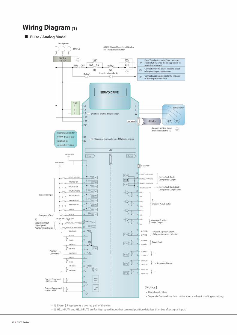
Wiring Diagram (1)
Pulse / Analog Model
• 1) Every ↕ P represents a twisted pair of the wire. • 2) HS_INPUT1 and HS_INPUT2 are for high speed input that can read position data less than 3us after signal input.
[ Notice ]
• Use shield cable • Separate Servo drive from noise source when installing or setting
DC
P
P
P
P
P
P
Input power
MCCB : Molded Case Circuit BreakerMC : Magnetic Contactor
Lamp for alarm display
Press 'Push button switch' that makes an electricity flow while it is being pressed, for more than 1 second.
Connect when the power needs to be cut off depending on the situation.
Connect surge suppressor to the relay coil of the magnetic contactor
This connector is valid for a 400W drive or over
Regenerative resistor.
A 400W drive or over
has a built-in
regenerative resister.
Don't use a 400W drive or under
Servo Motor
Sequence Input
Speed Command-10V to +10V
Current Command-10V to +10V
PositionCommand
16-bitA/D
12-bitA/D
INPUT1 (/SV-ON)
INPUT2 (P-OT)
INPUT3 (N-OT)
INPUT4 (/P-CON)
INPUT5 (/A-RST)
INPUT6 (/N-TL)
INPUT7 (/P-TL)
24V-PULS+
HF-PULS -
HF-PULS +
PULS -
PULS +
E-STOP
Servo Fault Code/Sequence Output
Encoder A, B, C pulse
Absolute PositionSerial Output
OUTPUT1+
OUTPUT1-
OUTPUT3+
OUTPUT3-
OUTPUT2+
OUTPUT2-
/Z-PULSE +
/Z-PULSE -
/FAULT +
/FAULT -
I/O
FCOM/OUTCOM
24V [or GND]
GND [or 24V]
FAULT 1 / OUTPUT 4
FAULT 3 / OUTPUT 6
FAULT 2 / OUTPUT 5
1
9
8
7
6
4
3
2
5
26
50
27
28
22
21
20
19
24
16
15
14
13
25
12
11
49
23
36
35
34
33
32
31
30
40
39
38
37
29
48
47
44
43
42
46
45
18
17
41
P
P
P
P
P
P
P
P
P
SERVO DRIVE
Connect a shield line of the heatsink to the F.G
2
2
INPUT8
GND [or 24V] 24V [or GND]
10
SIGN +
SIGN -
HF-SIGN +
HF-SIGN -
24V-SIGN +
USB PORT
INPUT9 / HS_INPUT1(REG1)
INPUT10 / HS_INPUT2(REG2)
150
150
EA +
EA -
EB +
EB -
EC +
EC -
PS +
PS -
Emergency Stop
Sequence Input/High Speed Position Registration
Servo Fault Code GND/Sequence Output GND
Encoder Z pulse Output (When using open collector)
Servo Fault
Sequence Output
1)
2)

DC
2
Input power
This connector is valid for a 400W drive or over
Don't use a drive with 400W or under
Servo Motor
Sequence Input
INPUT1 (/ENABLE)
INPUT2 (P-OT)
INPUT3 (N-OT)
INPUT4 (/HOME)
E-STOP
Encoder A, B pulse
Sequence Output
OUTPUT1+
OUTPUT1-
OUTPUT3+
OUTPUT3-
OUTPUT2+
OUTPUT2-
I/O
24V [or GND]
GND [or 24V]
1
9
8
7
6
4
3
5
14
13
12
11
20
19
18
17
16
15
P
P
P
P
P
SERVO DRIVE
Connect a shield line of the heatsink to the F.G
24V [or GND]GND [or 24V]
Touch Probe Signal Input
EtherCAT PORT
USB PORT
MCCB : Molded Case Circuit BreakerMC : Magnetic Contactor
Lamp for alarm display
Press 'Push button switch' that makes an electricity flow while it is being pressed, for more than 1 second.
Connect when the power needs to be cut off depending on the situation.
Connect surge suppressor to the relay coil of the magnetic contactor
Regenerative resistor.
A 400W drive or over
has a built-in
regenerative resister.
10
Touch_probe_1
Touch_probe_2
EA +
EA -
EB +
EB -
Emergency Stop
Wiring Diagram (2)
EtherCAT Model
• 1) Every ↕ P represents a twisted pair of the wire.
[ Notice ]
• Use shield cable
• Separate Servo drive from noise source when installing or setting
1)
CSD7 Series I 13
Reliable & Smart
14 I CSD7 Series
Reliable & Smart
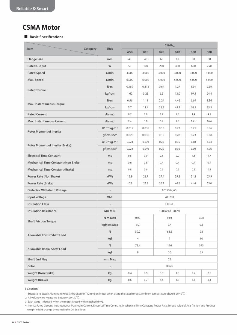
CSMA Motor
Basic Specifi cations
Item Category UnitCSMA_
A5B 01B 02B 04B 06B 08B
Flange Size mm 40 40 60 60 80 80
Rated Output W 50 100 200 400 600 750
Rated Speed r/min 3,000 3,000 3,000 3,000 3,000 3,000
Max. Speed r/min 6,000 6,000 5,000 5,000 5,000 5,000
Rated TorqueN·m 0.159 0.318 0.64 1.27 1.91 2.39
kgf·cm 1.62 3.25 6.5 13.0 19.5 24.4
Max. Instantaneous TorqueN·m 0.56 1.11 2.24 4.46 6.69 8.36
kgf·cm 5.7 11.4 22.9 45.5 68.2 85.3
Rated Current A(rms) 0.7 0.9 1.7 2.8 4.4 4.9
Max. Instantaneous Current A(rms) 2.4 3.0 5.9 9.5 15.1 16.6
Rotor Moment of InertiaX10-4kg·m2 0.019 0.035 0.15 0.27 0.71 0.86
gf·cm·sec2 0.020 0.036 0.15 0.28 0.73 0.88
Rotor Moment of Inertia (Brake)X10-4kg·m2 0.024 0.039 0.20 0.35 0.88 1.04
gf·cm·sec2 0.024 0.040 0.20 0.36 0.90 1.06
Electrical Time Constant ms 0.8 0.9 2.8 2.9 4.3 4.7
Mechanical Time Constant (Non Brake) ms 0.6 0.5 0.4 0.4 0.4 0.4
Mechanical Time Constant (Brake) ms 0.8 0.6 0.6 0.5 0.5 0.4
Power Rate (Non Brake) kW/s 12.9 28.7 27.4 59.2 51.2 65.9
Power Rate (Brake) kW/s 10.8 25.8 20.7 46.2 41.4 55.0
Dielectric Withstand Voltage - AC1500V, 60s
Input Voltage VAC AC 200
Insulation Class - Class F
Insulation Resistance MΩ MIN 100 (at DC 500V)
Shaft Friction TorqueN·m Max 0.02 0.04 0.08
kgf*cm Max 0.2 0.4 0.8
Allowable Thrust Shaft LoadN 39.2 68.6 98
kgf 4 7 10
Allowable Radial Shaft LoadN 78.4 196 343
kgf 8 20 35
Shaft End Play mm Max 0.2
Color - Black
Weight (Non Brake) kg 0.4 0.5 0.9 1.3 2.2 2.5
Weight (Brake) kg 0.6 0.7 1.4 1.8 3.1 3.4
[ Caution ]
1. Suppose to attach Aluminum Heat Sink(305x305xT12mm) on Motor when using the rated torque. Ambient temperature should be 40℃.2. All values were measured between 20~30℃.3. Each value is derived when the motor is used with matched drive.4. Inertia, Rated Current, Instantaneous Maximum Current, Electrical Time Constant, Mechanical Time Constant, Power Rate, Torque value of Axis friction and Product
weight might change by using Brake, Oil Seal Type.

CSD7 Series I 15
Reliable & Smart
CSMA Motor - Torque Speed Curves

16 I CSD7 Series
Reliable & Smart
CSMA Motor - External Dimension outline
CSMA Motor - External Dimension
Item Motor UnitCSMA_
A5B 01B 02B 04B 06B 08B
LLNon Brake 76.5 90.5 87.7 109.7 109.8 116.8
Brake 112 126 122.3 144.3 147.9 154.9
LUNon Brake 30.15 44.15 38.1 60.1 59.55 66.55
Brake 30.15 44.15 38.1 60.1 58.15 65.15
LY Brake Only - - - - - -
LR 25 25 30 30 35 35
L3 22.5 22.5 27 27 32 32
LE 2.5 2.5 3 3 3 3
LF 6.5 6.5 7.5 7.5 12 12
LQ 30 30 50 50 70 70
LC 40 40 60 60 80 80
LV 48.3 48.3 67.5 67.5 87.4 87.4
LT - - 80 80 105 105
LB 2 2 4 4 4 4
LZ 4.5 4.5 5.5 5.5 6.6 6.6
LA 46 46 70 70 90 90
Without Brake
With Brake
LB-ØLZ Through Hole
PCD LA
LT
LC
LV
LR
L3
LU
LLLE
LF
ØLQh7
LLLRLEL3
LF
LULY
CSD7 Series I 17
Reliable & Smart
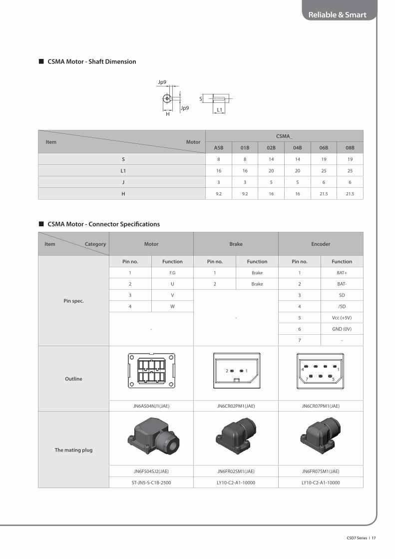
CSMA Motor - Shaft Dimension
Item Motor CSMA_
A5B 01B 02B 04B 06B 08B
S 8 8 14 14 19 19
L1 16 16 20 20 25 25
J 3 3 5 5 6 6
H 9.2 9.2 16 16 21.5 21.5
Jp9
HJp9
S
L1
CSMA Motor - Connector Specifi cations
Item Category Motor Brake Encoder
Pin spec.
Pin no. Function Pin no. Function Pin no. Function
1 F.G 1 Brake 1 BAT+
2 U 2 Brake 2 BAT-
3 V
-
3 SD
4 W 4 /SD
-
5 Vcc (+5V)
6 GND (0V)
7 -
Outline
JN6AS04NJ1(JAE) JN6CR02PM1(JAE) JN6CR07PM1(JAE)
The mating plug
JN6FS04SJ2(JAE) JN6FR02SM1(JAE) JN6FR07SM1(JAE)
ST-JN5-S-C1B-2500 LY10-C2-A1-10000 LY10-C2-A1-10000
4 3 2 1 2 1 4 1
7 5

18 I CSD7 Series
Reliable & Smart
CSMS Motor
Basic Specifi cations
Item category UnitCSMS_
10B 15B 20B 25B 30B 40B 50B
Flange Size mm 100 100 100 100 130 130 130
Rated Output kw 1 1.5 2 2.5 3 4 5
Rated Speed r/min 3,000 3,000 3,000 3,000 3,000 3,000 3,000
Max. Speed r/min 5000 5000 5000 5000 5000 5000 5000
Rated TorqueN·m 3.2 4.8 6.4 7.9 9.6 12.7 15.9
kgf·cm 32.7 48.7 65.3 80.6 97.4 129.6 162.2
Max. Instantaneous TorqueN·m 9.6 14.3 19.2 23.7 28.5 37.9 47.6
kgf·cm 98 145.9 195.9 241.8 290.8 386.7 485.7
Rated Current A(rms) 6.8 9.3 11.6 15.7 18.5 24.9 27.8
Max. Instantaneous Current A(rms) 20.5 28.7 33.1 45 53.7 72.4 81.2
Rotor Moment of InertiaX10-4kg·m2 1.99 2.85 3.7 4.57 7.71 10.17 12.63
gf·cm·sec2 2.03 2.91 3.78 4.66 7.87 10.38 12.89
Rotor Moment of Inertia (Brake)X10-4kg·m2 2.34 3.17 4.02 4.88 8.59 11.05 13.52
gf·cm·sec2 2.36 3.23 4.11 4.98 8.77 11.28 13.8
Electrical Time Constant ms 5.6 6.1 6.1 6.4 7.7 9.4 9.5
Mechanical Time Constant (Non Brake) ms 0.9 0.74 0.66 0.66 0.68 0.52 0.51
Mechanical Time Constant (Brake) ms 1.05 0.82 0.72 0.72 0.76 0.56 0.54
Power Rate (Non Brake) kW/s 51.6 79.9 110.6 136.6 118.1 158.6 200
Power Rate (Brake) kW/s 44.4 72 101.7 127.8 106 145.9 186.8
Dielectric Withstand Voltage - AC1500V, 60s
Voltage Specifi cations VAC AC 200
Input Voltage - Class F
Insulation Resistance MΩ MIN 100 (at DC500V)
Shaft Friction TorqueN·m Max 0.49 0.59 0.49
kgf*cm Max 5 6.0 5
Allowable Thrust Shaft LoadN 98
kgf 10
Allowable Radial Shaft LoadN 490
kgf 50
Shaft End Play mm Max 0.5
Color - Black
Weight (Non Brake) kg 3.4 4.2 5 5.8 8.3 8.9 9.4
Weight (Brake) kg 5.3 6.1 6.9 7.7 10.6 11.2 11.7
[ Caution ]
1. Suppose to attach Aluminum Heat Sink(450x450xT25mm) on Motor when using the rated torque. Ambient temperature should be 40℃.2. All values were measured between 20~30℃.3. Each value is derived when the motor is used with matched drive.4. Inertia, Mechanical Time Constant, Power Rate and Product weight might change by using Brake Type.

CSD7 Series I 19
Reliable & Smart
CSMS Motor - Torque Speed Curves
20 I CSD7 Series
Reliable & Smart
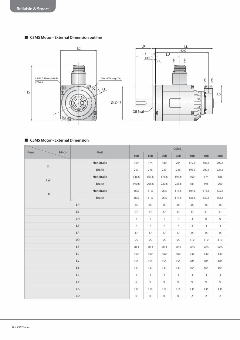
CSMS Motor - External Dimension outline
CSMS Motor - External Dimension
Item Motor UnitCSMS_
10B 15B 20B 25B 30B 40B 50B
LLNon Brake 159 174 189 204 172.5 186.5 200.5
Brake 203 218 233 248 193.5 207.5 221.5
LWNon Brake 146.6 161.6 176.6 191.6 160 174 188
Brake 190.6 205.6 220.6 235.6 181 195 209
LUNon Brake 66.5 81.5 96.5 111.5 104.5 118.5 132.5
Brake 66.5 81.5 96.5 111.5 125.5 139.5 153.5
LR 55 55 55 55 55 65 65
L3 47 47 47 47 47 61 61
LH 1 1 1 1 4 0 0
LE 7 7 7 7 4 4 4
LF 17 17 17 17 15 15 15
LQ 95 95 95 95 110 110 110
LS 50.4 50.4 50.4 50.4 50.5 50.5 50.5
LC 100 100 100 100 130 130 130
LV 155 155 155 155 185 185 185
LT 133 133 133 133 164 164 164
LB 4 4 4 4 4 4 4
LZ 9 9 9 9 9 9 9
LA 115 115 115 115 145 145 145
LD 0 0 0 0 2 2 2
LR
L3(LH)
LE LU
LF
LL(LW)
LS
Oil Seal
ØLQh7
D D
E E
LC
LD-M10 Through TapLB-ØLZ Through Hole
PCD LA
LVLT

CSD7 Series I 21
Reliable & Smart
CSMS Motor - Shaft Dimension
Item Motor CSMS_
10B 15B 20B 25B 30B 40B 50B
LP 24 24 24 24 24 - -
S 19 19 19 19 22 24 24
L1 45 45 55
I 6 8 8
J 6 7 7
H 21.5 25 27
J
H
Ih9 (key)
ØLP S
L1
CSMS Motor - Connector Specifi cation
Item Category Motor Encoder
Part no.
CSMS_ All Catalog
10B,15B,20B,25B 30B,40B,50B
N/MS3102A20-18P N/MS3102A24-11P JN2AS10ML2-R
Pin spec.
Pin no. Function Pin no. Function Pin no. Function
A - A (Brake) 1 GND (0V)
B W-phase B (Brake) 2 -
C - C - 3 SD
D - D U-phase 4 Vcc (+5V)
E F.G E V-phase 5 BAT-
F U-phase F W-phase 6 BAT+
G (Brake) G F.G 7 /SD
H (Brake) H - 8 -
I V-phase I - 9 Shield
- - 10 -
Outline
Viewed from D - D Viewed from D - D Viewed from E - E

22 I CSD7 Series
Reliable & Smart
CSMD Motor
Basic Specifi cations
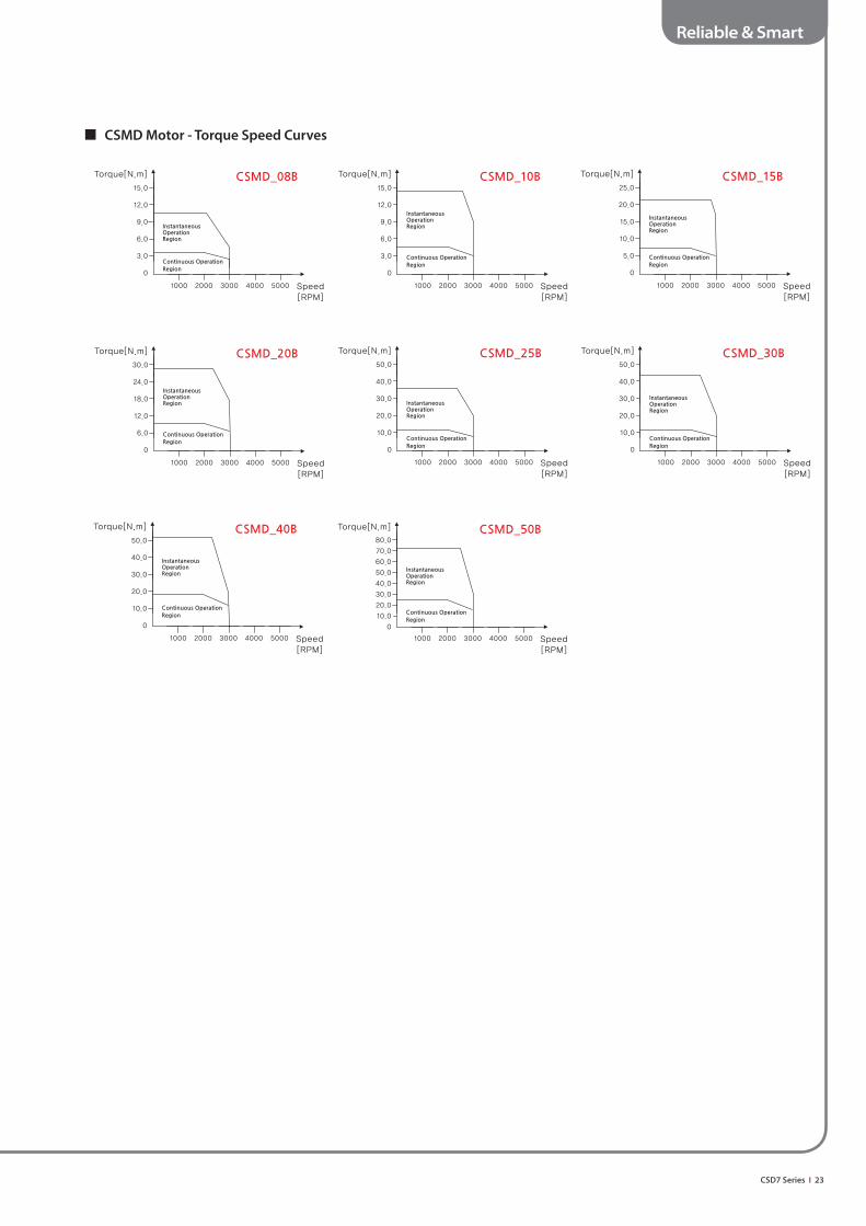
Item Category UnitCSMD_
08B 10B 15B 20B 25B 30B 40B 50B
Flange Size mm 130 130 130 130 130 130 180 180
Rated Output kw 0.75 1 1.5 2 2.5 3 4 5
Rated Speed r/min 2,000 2,000 2,000 2,000 2,000 2,000 2,000 2,000
Max. Speed r/min 3,000 3,000 3,000 3,000 3,000 3,000 3,000 3,000
Rated TorqueN·m 3.6 4.8 7.2 9.6 11.9 14.3 19.1 23.9
kgf·cm 36.5 48.7 72.9 97.4 121.4 145.9 194.9 243.9
Max. Instantaneous TorqueN·m 10.6 14.4 21.5 28.5 35.5 42.9 56.4 71.4
kgf·cm 108.1 146.9 219.4 290.8 362.2 437.7 575.5 728.6
Rated Current A(rms) 5 6.4 9.8 12.9 15.1 17.2 23 31.5
Max. Instantaneous Current A(rms) 13.5 18.2 28.2 37.2 43.9 50.5 65.9 91.4
Rotor Moment of InertiaX10-4kg·m2 3.49 5.6 7.71 7.71 10.17 12.63 41.3 56.8
gf·cm·sec2 3.56 5.71 7.87 7.87 10.38 12.89 42.1 58
Rotor Moment of Inertia (Brake)X10-4kg·m2 4.37 6.49 8.59 8.59 11.05 13.52 43.1 58.7
gf·cm·sec2 4.46 6.62 8.77 8.77 11.28 13.8 44 59.9
Electrical Time Constant ms 6 7.4 7.8 7.8 9.3 9.8 16.7 14.2
Mechanical Time Constant (Non Brake) ms 1.07 0.75 0.66 0.66 0.53 0.49 0.58 0.54
Mechanical Time Constant (Brake) ms 1.33 0.87 0.74 0.74 0.58 0.53 0.6 0.56
Power Rate (Non Brake) kW/s 36.6 40.7 66.2 118.1 139.1 161.8 88.4 93.2
Power Rate (Brake) kW/s 29.2 35.1 59.3 106 128 151.2 84.6 97.3
Dielectric Withstand Voltage - AC1500V, 60s
Input Voltage VAC AC 200
Insulation Class - Class F
Insulation Resistance MΩ MIN 100 (at DC500V)
Shaft Friction TorqueN·m Max 0.49 0.98
kgf*cm Max 5 10
Allowable Thrust Shaft LoadN 98 392
kgf 10 40
Allowable Radial Shaft LoadN 490 784
kgf 50 80
Shaft End Play mm Max 0.5
Color - Black
Weight (Non Brake) kg 6.5 7.4 8.3 8.3 8.9 9.4 14.5 20
Weight (Brake) kg 8.8 9.7 10.6 10.6 11.2 11.7 20.5 26
[ Caution ]
1. Suppose to attach Aluminum Heat Sink(Less than 3kw : 450x450xT25mm , Higher than 4kW : 600x600xT25mm) on Motor when using the rated torque. Ambient temperature should be 40℃.2. All values were measured between 20~30℃.3. Each value is derived when the motor is used with matched drive. 4. Inertia, Mechanical Time Constant, Power Rate and Product weight might change by using Brake Type.
CSD7 Series I 23
Reliable & Smart
CSMD Motor - Torque Speed Curves
24 I CSD7 Series
Reliable & Smart
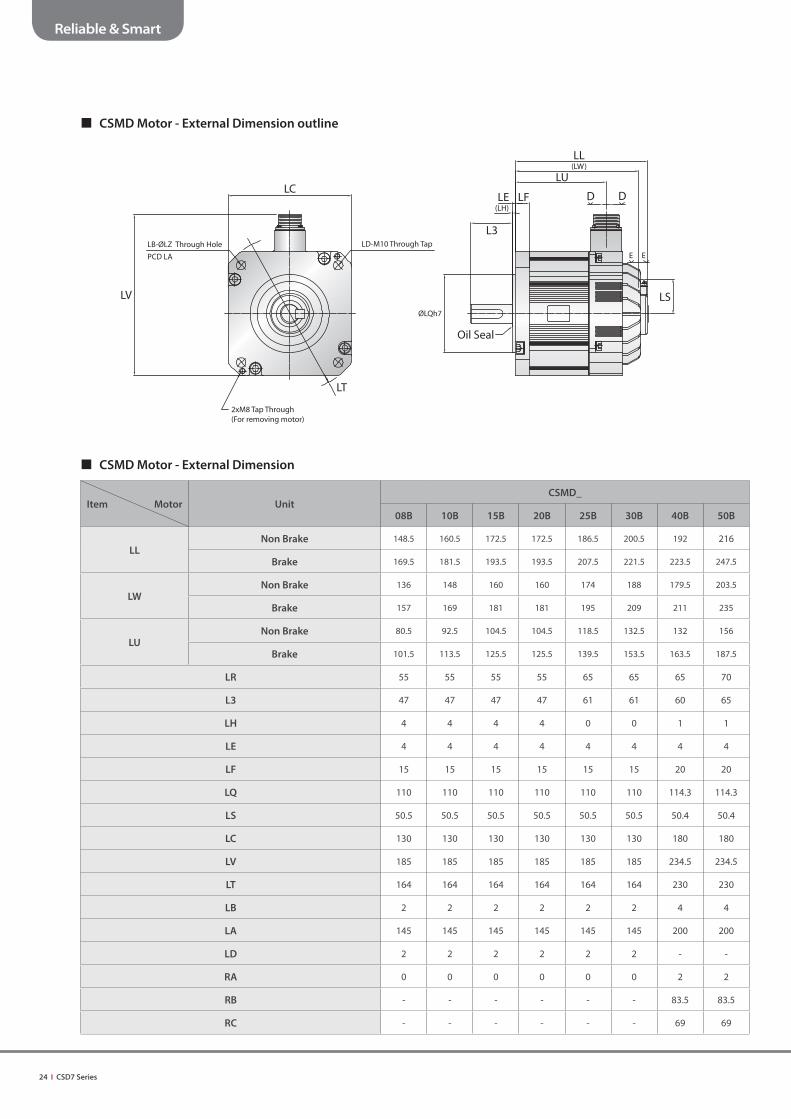
CSMD Motor - External Dimension outline
CSMD Motor - External Dimension
Item Motor UnitCSMD_
08B 10B 15B 20B 25B 30B 40B 50B
LLNon Brake 148.5 160.5 172.5 172.5 186.5 200.5 192 216
Brake 169.5 181.5 193.5 193.5 207.5 221.5 223.5 247.5
LWNon Brake 136 148 160 160 174 188 179.5 203.5
Brake 157 169 181 181 195 209 211 235
LUNon Brake 80.5 92.5 104.5 104.5 118.5 132.5 132 156
Brake 101.5 113.5 125.5 125.5 139.5 153.5 163.5 187.5
LR 55 55 55 55 65 65 65 70
L3 47 47 47 47 61 61 60 65
LH 4 4 4 4 0 0 1 1
LE 4 4 4 4 4 4 4 4
LF 15 15 15 15 15 15 20 20
LQ 110 110 110 110 110 110 114.3 114.3
LS 50.5 50.5 50.5 50.5 50.5 50.5 50.4 50.4
LC 130 130 130 130 130 130 180 180
LV 185 185 185 185 185 185 234.5 234.5
LT 164 164 164 164 164 164 230 230
LB 2 2 2 2 2 2 4 4
LA 145 145 145 145 145 145 200 200
LD 2 2 2 2 2 2 - -
RA 0 0 0 0 0 0 2 2
RB - - - - - - 83.5 83.5
RC - - - - - - 69 69
LC
LB-ØLZ Through Hole LD-M10 Through Tap
PCD LA
LV
2xM8 Tap Through(For removing motor)
LT
LL(LW)
LU
D DLE LF(LH)
L3
E E
LSØLQh7
Oil Seal

CSD7 Series I 25
Reliable & Smart
CSMD Motor - Shaft Dimension
Item Motor CSMD_
08B 10B 15B 20B 25B 30B 40B 50B
LP 24 24 24 24 - - 38 38
S 19 22 22 22 24 24 28 35
L1 45 45 55 55 55
I 6 8 8 8 10
J 6 7 7 7 8
H 21.5 25 27 31 38
J
Ih9 (key)
ØLP S
H L1
CSMD Motor - Connector Specifi cations
Item Category Motor Encoder
Part no.
CSMD_ All Catalog
08B,10B,15B,20B,25B 30B,40B,50B
N/MS3102A20-18P N/MS3102A24-11P JN2AS10ML2-R
Pin spec.
Pin no. Function Pin no. Function Pin no. Function
A - A (Brake) 1 GND (0V)
B W-phase B (Brake) 2 -
C - C - 3 SD
D - D U-phase 4 Vcc (+5V)
E F.G E V-phase 5 BAT-
F U-phase F W-phase 6 BAT+
G (Brake) G F.G 7 /SD
H (Brake) H - 8 -
I V-phase I - 9 Shield
- - 10 -
Outline
Viewed from D - D Viewed from D - D Viewed from E - E

26 I CSD7 Series
Reliable & Smart
CSMH Motor
Basic Specifi cations
Item Category UnitCSMH_
05B 10B 15B 20B 30B 40B 50B
Flange Size mm 130 130 130 180 180 180 180
Rated Output kw 0.5 1 1.5 2 3 4 5
Rated Speed r/min 2,000 2,000 2,000 2,000 2,000 2,000 2,000
Max. Speed r/min 3,000 3,000 3,000 3,000 3,000 3,000 3,000
Rated TorqueN·m 2.4 4.8 7.2 9.6 14.3 19.1 23.9
kgf·cm 24.4 48.7 72.9 97.4 145.9 194.9 243.9
Max. Instantaneous TorqueN·m 6 14.4 21.5 28.5 42.9 56.4 71.4
kgf·cm 61.2 146.9 219.4 290.8 437.8 575.5 728.6
Rated Current A(rms) 3.4 6.4 9.8 13.3 17.5 23 31.5
Max. Instantaneous Current A(rms) 7.6 18.2 28.2 37.3 50.4 65.9 91.4
Rotor Moment of InertiaX10-4kg·m2 12.63 26.1 42.7 61.7 92.5 115.8 170.1
gf·cm·sec2 12.89 26.6 43.6 63 94.4 118.2 173.6
Rotor Moment of Inertia (Brake)X10-4kg·m2 13.52 27 43.6 63.9 94.4 117.7 172
gf·cm·sec2 13.8 27.5 44.5 65 96.3 120.1 175.5
Electrical Time Constant ms 9.8 7.4 7.8 15.6 16.7 16.7 14.2
Mechanical Time Constant (Non Brake) ms 0.49 3.5 3.68 0.87 1.29 1.62 1.63
Mechanical Time Constant (Brake) ms 0.53 3.62 3.75 0.9 1.32 1.64 1.65
Power Rate (Non Brake) kW/s 4.53 8.74 11.9 14.8 22.1 31.5 33.6
Power Rate (Brake) kW/s 4.23 8.45 11.7 14.3 21.7 31 33.2
Dielectric Withstand Voltage - AC1500V, 60s
Input Voltage VAC AC 200
Insulation Class - Class F
Insulation Resistance MΩ MIN 100 (at DC500V)
Shaft Friction TorqueN·m Max 0.49 0.98
kgf*cm Max 5 10
Allowable Thrust Shaft LoadN 98 392
kgf 10 40
Allowable Radial Shaft LoadN 490 784
kgf 50 80
Shaft End Play mm Max 0.5
Color - Black
Weight (Non Brake) kg 9.4 9.2 11.1 18 20 21 24.8
Weight (Brake) kg 11.7 11.5 13.4 24.5 26.5 27.5 30.8
[ Caution ]
1. Suppose to attach Aluminum Heat Sink(Less than 1.5kw : 450x450xT25mm , Higher than 2kW : 600x600xT25mm) on Motor when using the rated torque. Ambient temperature should be 40℃.2. All values were measured between 20~30℃.3. Each value is derived when the motor is used with matched drive.4. Inertia, Mechanical Time Constant, Power Rate and Product weight might change by using Brake Type.

CSD7 Series I 27
Reliable & Smart
CSMH Motor - Torque Speed Curves
28 I CSD7 Series
Reliable & Smart
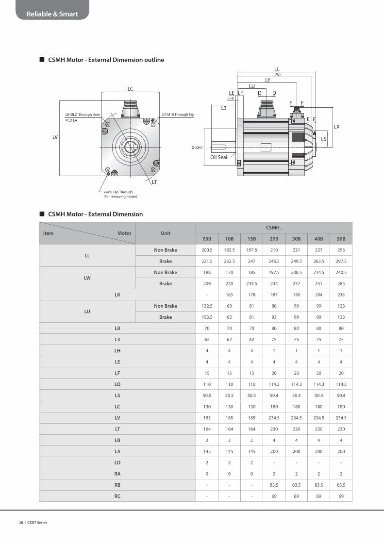
CSMH Motor - External Dimension
Item Motor UnitCSMH_
05B 10B 15B 20B 30B 40B 50B
LLNon Brake 200.5 182.5 197.5 210 221 227 253
Brake 221.5 232.5 247 246.5 249.5 263.5 297.5
LWNon Brake 188 170 185 197.5 208.5 214.5 240.5
Brake 209 220 234.5 234 237 251 285
LK - 163 178 187 190 204 238
LUNon Brake 132.5 69 81 88 99 99 123
Brake 153.5 62 81 93 99 99 123
LR 70 70 70 80 80 80 80
L3 62 62 62 75 75 75 75
LH 4 4 4 1 1 1 1
LE 4 4 4 4 4 4 4
LF 15 15 15 20 20 20 20
LQ 110 110 110 114.3 114.3 114.3 114.3
LS 50.5 50.5 50.5 50.4 50.4 50.4 50.4
LC 130 130 130 180 180 180 180
LV 185 185 185 234.5 234.5 234.5 234.5
LT 164 164 164 230 230 230 230
LB 2 2 2 4 4 4 4
LA 145 145 145 200 200 200 200
LD 2 2 2 - - - -
RA 0 0 0 2 2 2 2
RB - - - 83.5 83.5 83.5 83.5
RC - - - 69 69 69 69
CSMH Motor - External Dimension outline
LC
LB-ØLZ Through Hole LD-M10 Through Tap
PCD LA
2xM8 Tap Through(For removing motor)
LT
LL(LW)
LULE
(LH)
L3
ØLQh7
Oil Seal
LY
LF D D
F F
E ELX
LSLV

CSD7 Series I 29
Reliable & Smart
CSMH Motor - Shaft Dimension
Item Motor CSMH_
05B 10B 15B 20B 30B 40B 50B
LP 24 24 24 38 38 38 38
S 22 22 22 35 35 35 35
L1 45 55
I 8 10
J 7 8
H 25 38
J
Ih9 (key)
ØLP S
H L1
CSMH Motor - Connector Specifi cations
Item Category Motor Encoder Brake
Part no.
CSMH_
All Catalog
CSMH_
05B · 10B · 15B 20B · 30B · 40B · 50B 05B10B · 15B · 20B · 30B ·
40B · 50B
N/MS3102A20-18P N/MS3102A24-11P JN2AS10ML2-RIncluded in Motor
connectorN/MS3102A10SL-4P
Pin spec.
Pin no. Function Pin no. Function Pin no. Function Pin no. Function
A - A - 1 GND (0V) A Brake
B W-phase B - 2 - B Brake
C - C - 3 SD
-
D - D U-phase 4 Vcc (+5V)
E F.G E V-phase 5 BAT-
F U-phase F W-phase 6 BAT+
G (Brake) G F.G 7 /SD
H (Brake) H - 8 -
I V-phase I - 9 Shield
- - 10 -
Outline
Viewed from D - D Viewed from D - D Viewed from E - E Viewed from F - F

30 I CSD7 Series
Reliable & Smart
Cable Specifi cations
Motor Power Cable - CSMA
• Outline
• Connector Specification
Remark Description Specifi cation Marker
CON.AConnector JN6FS04SJ2
JAETerminal ST-JN5-S-C1B-2500
CON.BRING Terminal GP-140078 KET or Equivalent product
Ferrule Terminal CE010012 Dong-A Bestech
• Wiring Specification (Wire Gage : AWG 18)
PIN Function Color
1 Frame GND FG Wire (Green+Yellow)
2 U Phase 3 core cable : Red
3 V Phase 3 core cable : white
4 W Phase 3 core cable : Black
Motor Power Cable - CSMT
Remark Description Specifi cation Marker
CON.AConnector 172159-1
TETerminal 170362-1
CON.BRING Terminal GP-140078 KET or Equivalent product
Ferrule Terminal CE010012 Dong-A Bestech
PIN Function Color
1 U phase 3 core cable : Red
2 V phase 3 core cable : white
3 W phase 3 core cable : Black
4 Frame GND FG Wire (Green+Yellow)
• Connector Specification
• Wiring Specification (Wire Gage : AWG 18)
• Outline

CSD7 Series I 31
Reliable & Smart
Motor Power Cable - CSMS, CSMD, CSMH
• 1.5kW or less
- CSMS, CSMD and CSMH Motor - Wire Gage : Power (AWG 14), Brake (AWG 20)
• Connector Specification
* Wiring deleted at Non Brake Motor
Remark Description Specifi cation Marker
CON.A MS Connector MS3106A20-18S Military Standard Compliance product
CON.B
1.5kW or less RING Terminal (B1, B2) GP-140078 KET or Equivalent product
Ferrule Terminal CE025012 Dong-A Bestech
2.5kW or less RING Terminal (B1, B2) GP-140078 KET or Equivalent product
RING Terminal (U, V, W, FG) 4SQ-4Ø UL Approved product
• Wiring Specification
PIN Function Color
A - -
B W phase 3 core cable : Black
C - -
D - -
E Frame GND FG Wire (Green+Yellow)
F U phase 3 core cable : Red
G Brake (B1) 2 core cable : white, Brake Motor Only
H Brake (B2) 2 core cable : Black, Brake Motor Only
I V phase 3 core cable : white
• 2.5kW or less
- CSMS, CSMD Motor - Wire Gage : Power (AWG 12), Brake (AWG 20)
* Wiring deleted at Non Brake Motor
• Connector Specification
Remark Description Specifi cation Marker
CON.A MS Connector MS3106A24-11S Military Standard Compliance product
CON.B
3.5kW or less RING Terminal (B1, B2) GP-140078 KET or Equivalent product
RING Terminal (U, V, W, FG) 4SQ-4Ø UL Approved product
5kW or less RING Terminal (B1, B2) GP-140078 KET or Equivalent product
RING Terminal (U, V, W, FG) 5.5SQ-4Ø UL Approved product
• Wiring Specification
PIN Function Color
A Brake (B1) 2 core cable : white, Brake Motor Only
B Brake (B2) 2 core cable : Black, Brake Motor Only
C - -
D U Phase 3 core cable : Red
E V Phase 3 core cable : white
F W Phase 3 core cable : Black
G Frame GND FG Wire (Green+Yellow)
H - -
I - -
• 3kW or more
- CSMS, CSMD Motor - Wire Gage :
• Power : AWG 12 (3.5kW or less ), AWG 10 (5kW or less ) • Brake : AWG 20
• 2kW or more
- CSMH Motor - Wire Gage :
• Power : AWG 12 (3.5kW or less ), AWG 10 (5kW or less ) • Brake : AWG 20
* Wiring deleted at Non Brake Motor
32 I CSD7 Series
Reliable & Smart
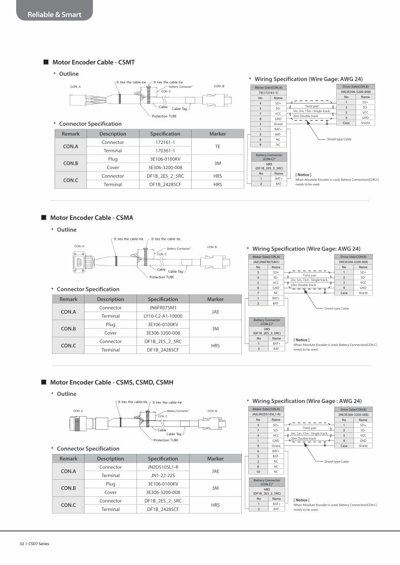
Motor Encoder Cable - CSMA
• Outline
• Connector Specification
Remark Description Specifi cation Marker
CON.AConnector JN6FR07SM1
JAETerminal LY10-C2-A1-10000
CON.BPlug 3E106-0100KV
3MCover 3E306-3200-008
CON.CConnector DF1B_2ES_2_5RC
HRSTerminal DF1B_2428SCF
• Wiring Specification (Wire Gage: AWG 24)
Motor Side(CON.A)
JAE(JN6FR07SM1)
No Name
3 SD+
4 SD-
5 VCC
6 GND
7 NC
1 BAT+
2 BAT-
Battery Connector
(CON.C)*
HRS
(DF1B_2ES_2_5RC)
No Name
1 BAT+
2 BAT-
Drive Side(CON.B)
3M(3E306-3200-008)
No Name
1 SD+
2 SD-
3 VCC
4 GND
Case Shield
Twist pair
Shield type Cable
Motor Encoder Cable - CSMS, CSMD, CSMH
• Outline
• Connector Specification
Remark Description Specifi cation Marker
CON.AConnector JN2DS10SL1-R
JAETerminal JN1-22-22S
CON.BPlug 3E106-0100KV
3MCover 3E306-3200-008
CON.CConnector DF1B_2ES_2_5RC
HRSTerminal DF1B_2428SCF
• Wiring Specification (Wire Gage : AWG 24)
Motor Side(CON.A)
JAE(JN2DS10SL1-R)
No Name
3 SD+
7 SD-
4 VCC
1 GND
9 Shield
6 BAT+
5 BAT-
2 NC
8 NC
10 NC
Battery Connector
(CON.C)*
HRS
(DF1B_2ES_2_5RC)
No Name
1 BAT+
2 BAT-
Drive Side(CON.B)
3M(3E306-3200-008)
No Name
1 SD+
2 SD-
3 VCC
4 GND
Case Shield
Twist pair
Shield type Cable
Motor Encoder Cable - CSMT
• Outline
• Connector Specification
Remark Description Specifi cation Marker
CON.AConnector 172161-1
TETerminal 170361-1
CON.BPlug 3E106-0100KV
3MCover 3E306-3200-008
CON.CConnector DF1B_2ES_2_5RC HRS
Terminal DF1B_2428SCF HRS
• Wiring Specification (Wire Gage: AWG 24)
Motor Side(CON.A)
TE(172161-1)
No Name
4 SD+
5 SD-
7 VCC
8 GND
3 Shield
1 BAT+
2 BAT-
6 NC
9 NC
Battery Connector
(CON.C)*
HRS
(DF1B_2ES_2_5RC)
No Name
1 BAT+
2 BAT-
Drive Side(CON.B)
3M(3E306-3200-008)
No Name
1 SD+
2 SD-
3 VCC
4 GND
Case Shield
Twist pair3m, 5m, 15m : Single track, 20m Double track
Shield type Cable
[ Notice ]
When Absolute Encoder is used, Battery Connection(CON.C) needs to be used.
3m, 5m, 15m : Single track, 20m Double track
[ Notice ]
When Absolute Encoder is used, Battery Connection(CON.C) needs to be used.
3m, 5m, 15m : Single track, 20m Double track
[ Notice ]
When Absolute Encoder is used, Battery Connection(CON.C) needs to be used.

CSD7 Series I 33
Reliable & Smart
Motor Brake Cable - CSMH
• Outline
• Connector Specification
Remark Description Specifi cation Marker
CON.A Connector MS3106B10SL-4S Military Standard Compliance product
CON.B RING Terminal GP-140078 KET or Equivalent product
• Wiring Specification (Wire Gage : AWG 20)
PIN Function Color
A B1 2 core cable : white
B B2 2 core cable : Black
Motor Brake Cable - CSMT
• Outline
• Connector Specification
Remark Description Specifi cation Marker
CON.AConnector 172233-1
TETerminal 170362-1
CON.B RING Terminal GP-140078 KET or Equivalent product
• Wiring Specification (Wire Gage : AWG 20)
PIN Function Color
1 B1 2 core cable : white
2 B2 2 core cable : Black
Motor Brake Cable - CSMA
• Outline
• Connector Specification
Remark Description Specifi cation Marker
CON.AConnector JN6FR02SM1
JAETerminal LY10-C2-A1-10000
CON.B RING Terminal GP-140078 KET or Equivalent product
• Wiring Specification (Wire Gage : AWG 20)
PIN Function Color
1 B1 2 core cable : white
2 B2 2 core cable : Black

34 I CSD7 Series
Reliable & Smart
RS485 Cable - 1) Drive To Drive
• Outline
• Connector Specification
Remark Description Specifi cation Marker
CON.A Industry mini I/O Kit 2040008-1 TE
CON.BConnector SMP-05V-NC
JSTTerminal SHF-001T-0.8BS
CON.CConnector SMR-05V-N
JSTTerminal SYM-001T-P0.6
• Wiring Specification (Wire Gage : AWG 26)
Drive Side(CON.A)
Tyco(2040008-1)
No Name
1 GND
2 VCC
3 RX-
4 RX+
Case Shield
5 GND
6 N.C
7 RX-
8 RX+
Case Shield
Connector Side(CON.B)
JST(SMP-05V-NC)
No Name
4 GND
1 VCC
3 RX-
2 RX+
5 FG
Twist pair
Shield type Cable
Connector Side(CON.C)
JST(SMR-05V-N)
No Name
4 GND
1 N.C
3 RX-
2 RX+
5 F.G
Twist pair
RS485 Cable - 2) Drive To Controller
• Outline
• Connector Specification
Remark Description Specifi cation Marker
CON.DConnector SMP-05V-NC
JSTTerminal SHF-001T-0.8BS
• Wiring Specification (Wire Gage : AWG 26)JST(SMP-05V-NC)
No Name
1 NC
2 RX+
3 RX-
4 GND
5 F.G
RX+
RX-
GND
Shield
Twist pair
RS485 Termination Connector
• Outline
• Connector Specification
Remark Description Specifi cation Marker
CON.DConnector SMR-05V-N
JSTTerminal SYM-001T-P0.6
• Wiring Specification
Connector Side(CON.D)
JST(SMR-05V-N)
No Name
4 GND
1 VCC
3 RX-
2 RX+
5 F.G 4.7K
4.7K
220
* Cover with black protection tube
* Resistance Standards : 1/8W, J Type
CSD7 Series I 35
Reliable & Smart
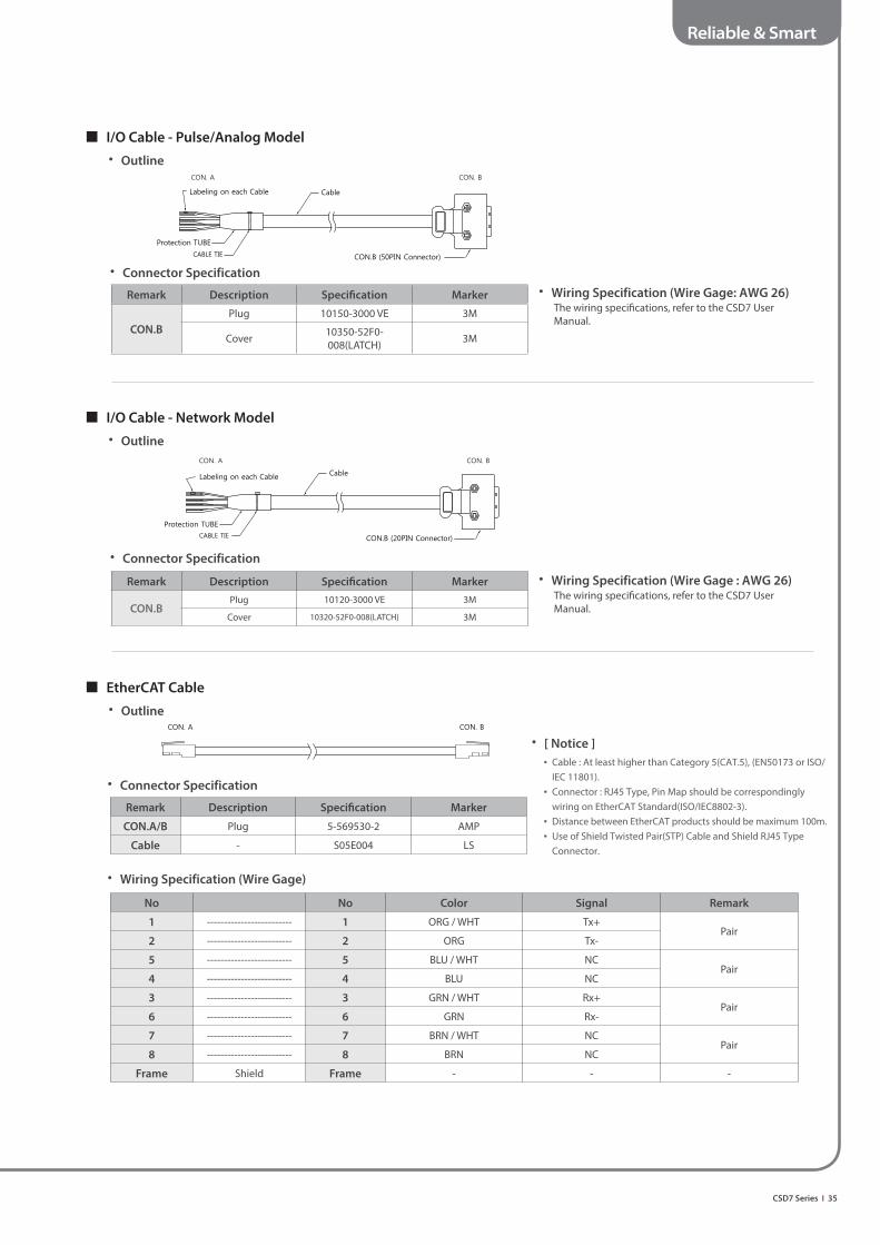
I/O Cable - Pulse/Analog Model
• Outline
• Connector Specification
Remark Description Specifi cation Marker
CON.B
Plug 10150-3000 VE 3M
Cover 10350-52F0-008(LATCH) 3M
I/O Cable - Network Model
• Outline
• Connector Specification
Remark Description Specifi cation Marker
CON.BPlug 10120-3000 VE 3M
Cover 10320-52F0-008(LATCH) 3M
• Wiring Specification (Wire Gage : AWG 26)The wiring specifi cations, refer to the CSD7 User Manual.
EtherCAT Cable
• Outline
• Connector Specification
Remark Description Specifi cation Marker
CON.A/B Plug 5-569530-2 AMP
Cable - S05E004 LS
• Wiring Specification (Wire Gage: AWG 26)The wiring specifi cations, refer to the CSD7 User Manual.
• [ Notice ]
• Cable : At least higher than Category 5(CAT.5), (EN50173 or ISO/IEC 11801).
• Connector : RJ45 Type, Pin Map should be correspondingly wiring on EtherCAT Standard(ISO/IEC8802-3).
• Distance between EtherCAT products should be maximum 100m. • Use of Shield Twisted Pair(STP) Cable and Shield RJ45 Type
Connector.
• Wiring Specification (Wire Gage)
No No Color Signal Remark
1 ------------------------- 1 ORG / WHT Tx+Pair
2 ------------------------- 2 ORG Tx-
5 ------------------------- 5 BLU / WHT NCPair
4 ------------------------- 4 BLU NC
3 ------------------------- 3 GRN / WHT Rx+Pair
6 ------------------------- 6 GRN Rx-
7 ------------------------- 7 BRN / WHT NCPair
8 ------------------------- 8 BRN NC
Frame Shield Frame - - -

38, Jinwisandan-ro, Jinwi-myeon, Pyeongtaek-si, Gyeonggi-do, Korea, Zip code : 17709
Copyright © 2016 RS Automation Co., Ltd. All Rights Reserved.
Publication CSD7-CA004A-EN-P–May 2016