High-Performance Pan-Tilt Unit - Flir.com · High-Performance Pan-Tilt Unit User Manual MODELS:...
72
High-Performance Pan-Tilt Unit User Manual MODELS: PTU-D48E PTU-D100E PTU-D300E VERSION: 1.00 REVISION DATE: June, 2016
Transcript of High-Performance Pan-Tilt Unit - Flir.com · High-Performance Pan-Tilt Unit User Manual MODELS:...
High-Performance
Pan-Tilt Unit
User Manual
MODELS: PTU-D48EPTU-D100EPTU-D300E
VERSION: 1.00REVISION DATE: June, 2016

PTU-D48, D100, D300 User Manual
DOCUMENT CONTROL
COPYRIGHT NOTICEPTU-D48E, D100, D300 User’s Manual, version 1.00 (06/2016)©2016 by FLIR Systems, Inc., 70 Castilian Drive, Goleta, CA 93117, (805)964-9797, FAX: (805)690-5933www.FLIR.com/MCSAll rights reserved. Protected under numerous U.S. patents, including 5463432 and 5802412 with otherpatents pending. No part of this book may be reproduced, stored in a retrieval system, or transcribed inany form or by any means including but not limited to electronic, mechanical, photocopying, recording,or otherwise, without the prior written permission of FLIR Systems, Inc.
The information in this manual is subject to change without notice and, except for the warranty, doesnot represent a commitment on the part of FLIR Systems, Inc. FLIR Systems, Inc. cannot be held liable forany mistakes in this manual and reserves the right to make changes.
Date Author Rev. # Changes
06/2016 A. Hernandez 1.00 Initial release
Copyright 2016, FLIR Commercial Systems, Inc.
Table of Contents
1 - Introduction ................................................................................................................................. 11.1 - General PTU Features ........................................................................................................................ 1
1.1.1 - PTU-D48E Features ................................................................................................................... 21.1.2 - PTU-D100E Features ................................................................................................................. 21.1.3 - PTU-D300E Features ................................................................................................................. 2
1.2 - E Series Features ........................................................................................................................... 31.3 - Applications ....................................................................................................................................... 31.4 - About This Manual ............................................................................................................................ 4
1.4.1 - Formatting Conventions ........................................................................................................... 41.5 - Models ............................................................................................................................................... 5
1.5.1 - PTU-D48E Models ..................................................................................................................... 51.5.2 - PTU-D48E ISM Models .............................................................................................................. 51.5.3 - PTU-D100E Models ................................................................................................................... 61.5.4 - PTU-D100E ISM Models ............................................................................................................ 61.5.5 - PTU-D300E Models ................................................................................................................... 71.5.6 - PTU-D300E ISM Models ............................................................................................................ 71.5.7 - PTU-D300E RF Models .............................................................................................................. 8
1.6 - PTU Package Contents ...................................................................................................................... 81.7 - Related Documentation .................................................................................................................... 91.8 - Additional Resources ......................................................................................................................... 91.9 - Technical Support .............................................................................................................................. 9
2 - Safety ..........................................................................................................................................112.1 - Overview ......................................................................................................................................... 112.2 - Safety Warnings and Cautions ......................................................................................................... 11
3 - Quick Start ..................................................................................................................................133.1 - System Overview ............................................................................................................................. 133.2 - Installation Components ................................................................................................................. 143.3 - Basic Setup ...................................................................................................................................... 143.4 - Ethernet Connection ....................................................................................................................... 153.5 - Serial Connection ............................................................................................................................ 16
4 - Installation & Setup .....................................................................................................................194.1 - Mounting the Unit ........................................................................................................................... 194.2 - Wiring and Connectors .................................................................................................................... 20
4.2.1 - Mechanical Overview ............................................................................................................. 204.2.2 - Wiring Options ........................................................................................................................ 20
4.3 - Power Sources ................................................................................................................................. 214.4 - Fusing .............................................................................................................................................. 224.5 - Shielding .......................................................................................................................................... 224.6 - Interface and Host Settings ............................................................................................................. 22
4.6.1 - Ethernet Connection .............................................................................................................. 234.6.2 - RS-232 Electrical Connection .................................................................................................. 234.6.3 - RS-485 Electrical Connection .................................................................................................. 24
Copyright 2016, FLIR Commercial Systems, Inc. iii
PTU-D48, D100, D300 User Manual
4.7 - Initial Power-Up and Test ................................................................................................................ 244.7.1 - Web Interface ......................................................................................................................... 244.7.2 - Terminal Interface .................................................................................................................. 25
4.8 - Payload Mounting ........................................................................................................................... 254.8.1 - Side Bracket Attachment ........................................................................................................ 264.8.2 - Payload Attachment ............................................................................................................... 27
4.9 - Payload Wiring Connector (Optional for D48E) .............................................................................. 29
5 - Configuring & Programming ....................................................................................................... 315.1 - Range of Motion .............................................................................................................................. 31
5.1.1 - Default Limits ......................................................................................................................... 325.2 - Resolution and Step Modes ............................................................................................................ 32
5.2.1 - PTU-D48E Resolution ............................................................................................................. 335.2.2 - PTU-D100E Resolution ........................................................................................................... 335.2.3 - PTU-D300E Resolution ........................................................................................................... 33
5.3 - User-Programmable Settings .......................................................................................................... 335.3.1 - High-Speed Operation ............................................................................................................ 345.3.2 - Heavy-Payload Operation ....................................................................................................... 345.3.3 - Battery Powered Operation ................................................................................................... 35
F - Electrical Specifications ................................................................................................................. 16.1 - 32-Pin Base Connector ...................................................................................................................... 26.2 - 19-Pin Payload Connector ................................................................................................................. 36.3 - PL01 Wiring Diagram ......................................................................................................................... 46.4 - PL02 Wiring Diagram ......................................................................................................................... 56.5 - PL17 Wiring Diagram (General) ......................................................................................................... 66.6 - PL17 Wiring Diagram (PTU-D100E with Slip Ring Only) .................................................................... 76.7 - Configurable I/O Wiring Diagram (PTU-D300E GigE Only) ................................................................ 86.8 - 32-Pin Breakout Cable ....................................................................................................................... 9
G - Mechanical Drawings ................................................................................................................... 17.1 - Payload Mounting Pattern ................................................................................................................ 1
7.1.1 - PTU-D48E .................................................................................................................................. 17.1.2 - PTU-D100E ................................................................................................................................ 37.1.3 - PTU-D300E ................................................................................................................................ 5
7.2 - PTU Dimensions ................................................................................................................................ 77.2.1 - PTU-D48E (Standard) ................................................................................................................ 77.2.2 - PTU-D48E (ISM) ........................................................................................................................ 87.2.3 - PTU-D100E (Standard) .............................................................................................................. 97.2.4 - PTU-D300E (Standard) ............................................................................................................ 10
Copyright 2016, FLIR Commercial Systems, Inc.iv
Table of Contents
H - Networking .................................................................................................................................. 18.1 - Ethernet ............................................................................................................................................. 18.2 - Serial .................................................................................................................................................. 1
8.2.1 - Serial Networking Connections ................................................................................................ 28.2.2 - ASCII Command Syntax ............................................................................................................ 38.2.3 - Serial Command List ................................................................................................................. 4
I - Troubleshooting ............................................................................................................................ 19.1 - Mechanical ........................................................................................................................................ 19.2 - Power ................................................................................................................................................ 19.3 - Networking ........................................................................................................................................ 19.4 - Technical Support .............................................................................................................................. 2
J - Regulatory & Warranty Information ............................................................................................. 110.1 - Regulatory Information ................................................................................................................... 110.2 - About FLIR Systems, Inc. .................................................................................................................. 210.3 - Limited Warranty ............................................................................................................................ 2
Copyright 2016, FLIR Commercial Systems, Inc. v

PTU-D48, D100, D300 User Manual
This page intentionally left blank.
Copyright 2016, FLIR Commercial Systems, Inc.vi

1 - Introduction
The PTU-D48E, PTU-D100E, and PTU-D300E E Series Pan-Tilt Units (PTU) from FLIR Systems, Inc. provide fast, accurate, and durable positioning of cameras, antennas, lasers, and other payloads. This User Manual contains setup, general configuration, wiring, and mechanical interface information that is intended for use by design engineers and integrators who are configuring, installing, and programming the PTU. Please see “Related Documentation” on page 9 for a list of other documents related to FLIR PTUs. PTU-D100E, and/or PTU-D300E.This manual describes setting up and using the following PTUs:• PTU-D48E
• PTU-D48E-ISM• PTU-D100E• PTU-D100E-ISM
• PTU-D300E• PTU-D300E-ISM• PTU-D300E GigE
Optional modules are not included in these instructions. If your PTU includes any optional modules, please refer to the documentation included with those modules for help with their setup and use.
1.1 - General PTU FeaturesThe PTU-D48E, PTU-D100E, and PTU-D300E PTUs offer the following general features:
• Serial communication capability via terminal or computer• Precise position, speed & acceleration control• On-the-fly position and speed changes
• Self-calibration on reset with reduced motion• Host-controllable power consumption
• Simple ASCII command mode• High-speed binary command interface• Constant-current motor drives for increased performance and control
Copyright 2016, FLIR Commercial Systems, Inc. 1
PTU-D48, D100, D300 User Manual
• Unregulated 12-30 VDC power input• Flexible connectivity options
• Sealed for outdoor operation (IP67)• Slip ring for continuous 360° pan operation (Optional with D48E; standard on D100E and D300E).
1.1.1 - PTU-D48E FeaturesIn addition to the general features listed above, the PTU-D48E offers the following features:
• Payload (top mount): 10lbs• Payload (side mount): 15lbs• Pan Resolution: 0.006°
• Tilt Resolution: 0.003°Please refer to the PTU-D48E Product Datasheet for complete specifications.
1.1.2 - PTU-D100E FeaturesIn addition to the general features listed above, the PTU-D100E offers the following features:• Payload (top mount): 15lbs (standard) or 25lbs (EX model)
• Payload (side mount): 25lbs• Pan Resolution: 0.0075°• Tilt Resolution: 0.0075° (standard) or 0.0038° (EX model)
Please refer to the PTU-D100E Product Datasheet for complete specifications.
1.1.3 - PTU-D300E FeaturesIn addition to the general features listed above, the PTU-D300E offers the following features:• Payload (top mount): 35lbs (standard) or 60lbs (EX model)• Payload (side mount): 75lbs (standard) or 90lbs (EX model)
• Pan Resolution: 0.006° (standard) or 0.003° (EX model)• Tilt Resolution: 0.006° (standard) or 0.003° (EX model)Please refer to the PTU-D300E Product Datasheet for complete specifications.
Copyright 2016, FLIR Commercial Systems, Inc.2
Chapter 1: Introduction
1.2 - E Series FeaturesThe PTU-D48E, PTU-D100E, and PTU-D300E E Series PTUs include the following new features:• Built-in Ethernet/Web IP interface for easy configuration, control, and diagnostics
• Gigabit Ethernet pass-through (PTU-D300E GigE only)• Improved power protection circuitry
• 32-pin base connector for simplified wiring• Integrated digital encoder for more robust positioning• Programmable ranges of motion
• Higher command rates with lower latency and jitter• Reduced calibration movement• Full backward compatibility with previous PTU models that includes:
- Mounting pattern- Payload connector/pin-outs (PL01, PL02)- ASCII and binary application command interface
- Optional 19- to 32-pin adapter cable (32-pin breakout cable also available)- Overlapped capabilities with previous PTU-D48E, PTU-D100E, and PTU-D300E models.
1.3 - ApplicationsThe PTU-D48E, PTU-D100E, and PTU-D300E E Series PTUs are well suited for the following applications:
• Mid- and short-range surveillance systems• Automated detection and tracking• Multi-sensor perimeter monitoring systems
• Thermal and IR cameras• Marine/shipboard sensor systems• Harbor and port security
• Border security & law enforcement• Highway & transportation monitoring
• Military special operations• Satellite communications systems• Microwave antenna systems (passive, active)
• Robotics & computer vision.
E
Copyright 2016, FLIR Commercial Systems, Inc. 3
PTU-D48, D100, D300 User Manual
1.4 - About This ManualThis section describes the formatting conventions and information contained in this manual.
1.4.1 - Formatting ConventionsThis manual uses several formatting conventions to present information of special importance.
Commands and other information that is new for the E Series PTUs include the “E” icon shown here.Lists of items, points to consider, or procedures that do not need to be performed in a specific order appear in bullet format:• Item 1• Item 2
Procedures that must be followed in a specific order appear in numbered steps:1. Perform this step first.2. Perform this step second.
Specific keyboard keys are depicted in square brackets and are capitalized, for example: [ESC]. If more than one key should be pressed simultaneously, the notation will appear as [KEY1]+[KEY 2], for example [ALT]+[F4].
Interface elements such as document titles, fields, windows, tabs, buttons, commands, options, and icons appear in bold text.Menus and submenus have the notation Menu>Submenu. For example, “Select File>Save” means that you should first open the File menu, and then select the Save option.Specific commands appear in standard Courier font. Sequences of commands appear in the order in which you should execute them and include horizontal or vertical spaces between commands.
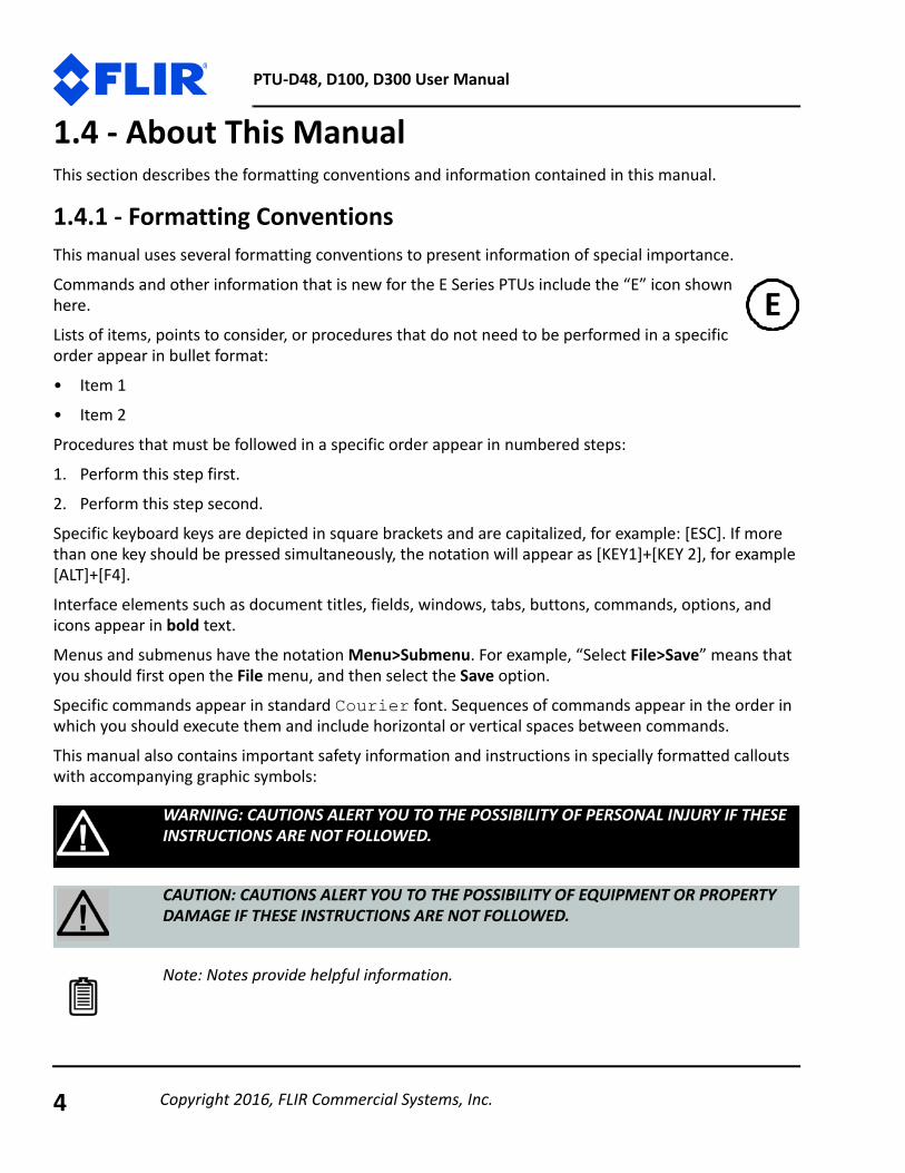
This manual also contains important safety information and instructions in specially formatted callouts with accompanying graphic symbols:
WARNING: CAUTIONS ALERT YOU TO THE POSSIBILITY OF PERSONAL INJURY IF THESE INSTRUCTIONS ARE NOT FOLLOWED.
CAUTION: CAUTIONS ALERT YOU TO THE POSSIBILITY OF EQUIPMENT OR PROPERTY DAMAGE IF THESE INSTRUCTIONS ARE NOT FOLLOWED.
Note: Notes provide helpful information.
E
Copyright 2016, FLIR Commercial Systems, Inc.4
Chapter 1: Introduction
1.5 - ModelsEach PTU unit includes a model number that is located on the base of the unit. This number lists the options present on that particular unit. Different options may require specialized instructions, and this manual will refer to this section where necessary to ensure that you are following the appropriate directions.
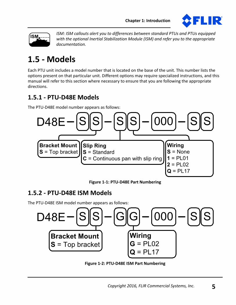
1.5.1 - PTU-D48E ModelsThe PTU-D48E model number appears as follows:
Figure 1-1: PTU-D48E Part Numbering
1.5.2 - PTU-D48E ISM ModelsThe PTU-D48E ISM model number appears as follows:
Figure 1-2: PTU-D48E ISM Part Numbering
ISM: ISM callouts alert you to differences between standard PTUs and PTUs equipped with the optional Inertial Stabilization Module (ISM) and refer you to the appropriate documentation.
ISM
S S S S S S000D48E
Bracket MountS = Top bracket
WiringS = None1 = PL012 = PL02Q = PL17
Slip RingS = StandardC = Continuous pan with slip ring
S S G G S S000D48EBracket MountS = Top bracket
WiringG = PL02Q = PL17
Copyright 2016, FLIR Commercial Systems, Inc. 5
PTU-D48, D100, D300 User Manual
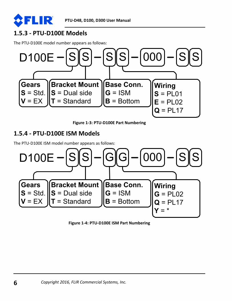
1.5.3 - PTU-D100E ModelsThe PTU-D100E model number appears as follows:
Figure 1-3: PTU-D100E Part Numbering
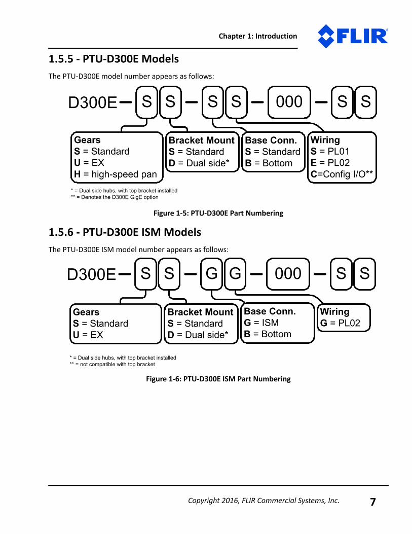
1.5.4 - PTU-D100E ISM ModelsThe PTU-D100E ISM model number appears as follows:
Figure 1-4: PTU-D100E ISM Part Numbering
Bracket MountS = Dual sideT = Standard
WiringS = PL01E = PL02Q = PL17
Base Conn.G = ISMB = Bottom
GearsS = Std.V = EX
Bracket MountS = Dual sideT = Standard
WiringG = PL02Q = PL17Y = *
Base Conn.G = ISMB = Bottom
GearsS = Std.V = EX
Copyright 2016, FLIR Commercial Systems, Inc.6
Chapter 1: Introduction
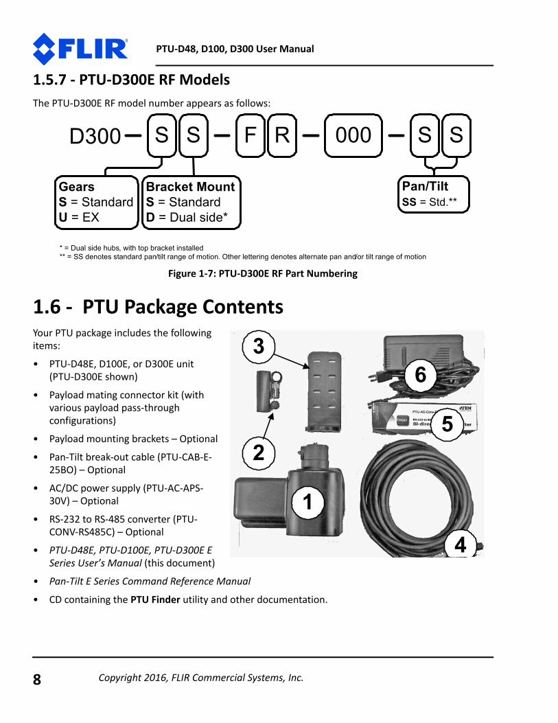
1.5.5 - PTU-D300E ModelsThe PTU-D300E model number appears as follows:
Figure 1-5: PTU-D300E Part Numbering
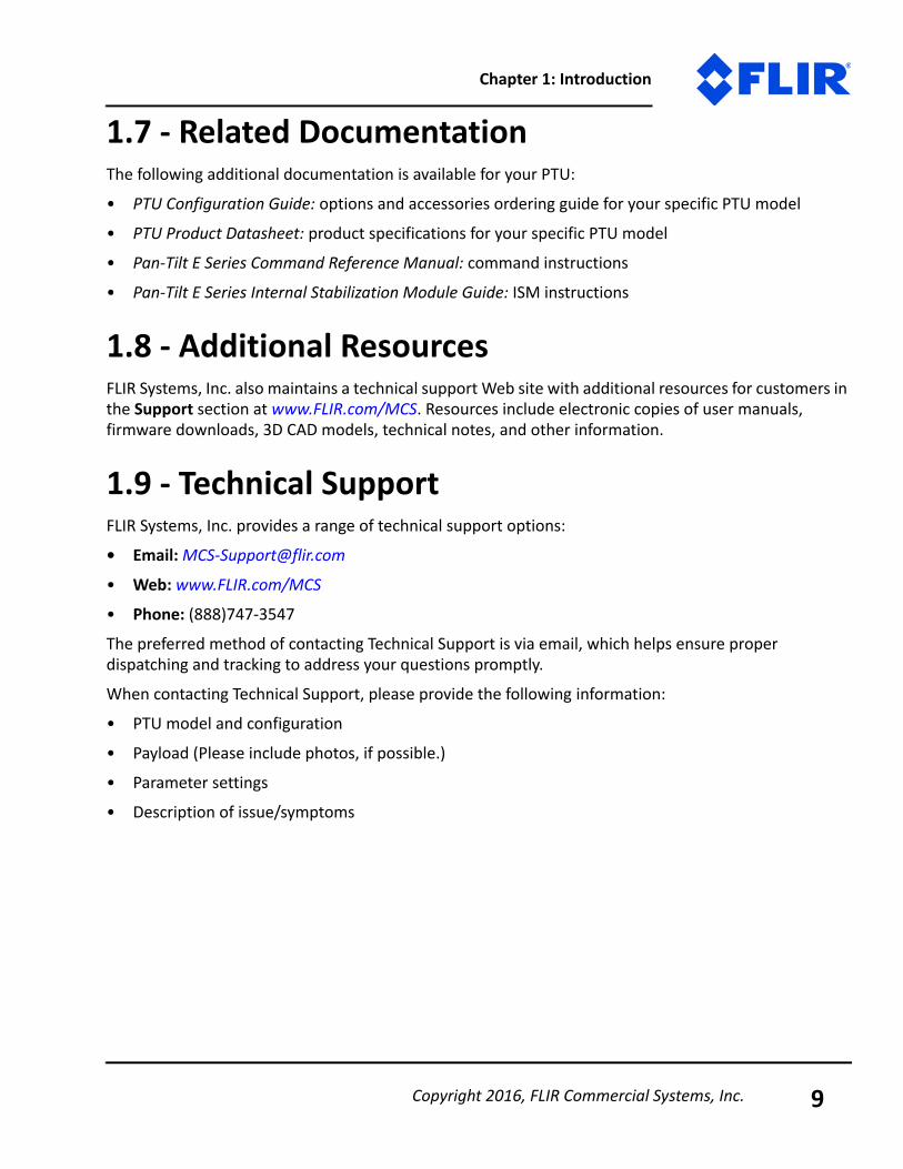
1.5.6 - PTU-D300E ISM ModelsThe PTU-D300E ISM model number appears as follows:
Figure 1-6: PTU-D300E ISM Part Numbering
S S S S000D300E
GearsS = StandardU = EXH = high-speed pan
* = Dual side hubs, with top bracket installed** = Denotes the D300E GigE option
Bracket MountS = StandardD = Dual side*
S S
WiringS = PL01E = PL02C=Config I/O**
Base Conn.S = StandardB = Bottom
S S S S000D300E
GearsS = StandardU = EX
* = Dual side hubs, with top bracket installed** = not compatible with top bracket
Bracket MountS = StandardD = Dual side*
G G
WiringG = PL02
Base Conn.G = ISMB = Bottom
Copyright 2016, FLIR Commercial Systems, Inc. 7
PTU-D48, D100, D300 User Manual
1.5.7 - PTU-D300E RF ModelsThe PTU-D300E RF model number appears as follows:
Figure 1-7: PTU-D300E RF Part Numbering
1.6 - PTU Package ContentsYour PTU package includes the following items:• PTU-D48E, D100E, or D300E unit
(PTU-D300E shown)• Payload mating connector kit (with
various payload pass-through configurations)
• Payload mounting brackets – Optional• Pan-Tilt break-out cable (PTU-CAB-E-
25BO) – Optional • AC/DC power supply (PTU-AC-APS-
30V) – Optional
• RS-232 to RS-485 converter (PTU-CONV-RS485C) – Optional
• PTU-D48E, PTU-D100E, PTU-D300E E Series User’s Manual (this document)
• Pan-Tilt E Series Command Reference Manual
• CD containing the PTU Finder utility and other documentation.
S S F R S S000D300
GearsS = StandardU = EX
Bracket MountS = StandardD = Dual side*
Pan/TiltSS = Std.**
* = Dual side hubs, with top bracket installed** = SS denotes standard pan/tilt range of motion. Other lettering denotes alternate pan and/or tilt range of motion
1
2
3
4
5
6
Copyright 2016, FLIR Commercial Systems, Inc.8
Chapter 1: Introduction
1.7 - Related DocumentationThe following additional documentation is available for your PTU:• PTU Configuration Guide: options and accessories ordering guide for your specific PTU model
• PTU Product Datasheet: product specifications for your specific PTU model• Pan-Tilt E Series Command Reference Manual: command instructions
• Pan-Tilt E Series Internal Stabilization Module Guide: ISM instructions
1.8 - Additional ResourcesFLIR Systems, Inc. also maintains a technical support Web site with additional resources for customers in the Support section at www.FLIR.com/MCS. Resources include electronic copies of user manuals, firmware downloads, 3D CAD models, technical notes, and other information.
1.9 - Technical SupportFLIR Systems, Inc. provides a range of technical support options:• Email: [email protected]
• Web: www.FLIR.com/MCS
• Phone: (888)747-3547The preferred method of contacting Technical Support is via email, which helps ensure proper dispatching and tracking to address your questions promptly.When contacting Technical Support, please provide the following information:• PTU model and configuration
• Payload (Please include photos, if possible.)• Parameter settings• Description of issue/symptoms
Copyright 2016, FLIR Commercial Systems, Inc. 9

PTU-D48, D100, D300 User Manual
This page intentionally left blank.
Copyright 2016, FLIR Commercial Systems, Inc.10

2 - Safety
2.1 - OverviewThis chapter contains important safety instructions. You must read, understand, and comply with all of these safety instructions in order to protect both persons and property. The benefits of a safe installation include increased usability, reliability, and reduced damage to the PTU, payload, and/or other property.
2.2 - Safety Warnings and Cautions• PTU installation and setup should be only be performed by qualified personnel.
• The installation must comply with all applicable codes (such as building codes, marine safety codes, etc.).
• The installation must be free of obstructions throughout the entire range of pan-tilt motion. When planning the installation, make sure to take the payload into account to ensure that the PTU and payload remain unobstructed at all times.
• All mounting methods and materials must be capable of supporting at least four times the combined weight of the PTU, mounted payloads, and cabling.
• Corrosion-resistant hardware (such as stainless steel screws) must be used for all outdoor installations.
• Do not install the PTU in any location that exceeds the PTU’s environmental specifications.• Always incorporate a readily accessible power disconnect into the installation wiring. (See “Ethernet
Connection” on page 15 and “Serial Connection” on page 16.)
• Removing power by disconnecting the power cable or cable harness is not recommended and can result in damage to the system.
• All service procedures must be performed by qualified service personnel in accordance with all applicable instructions.
• If the PTU is damaged, immediately remove power and contact FLIR Systems, Inc.
• Only use replacement parts recommended by FLIR Systems, Inc.• Use caution when lifting the PTU and/or payload.
Copyright 2016, FLIR Commercial Systems, Inc. 11

PTU-D48, D100, D300 User Manual
• Keep all persons and objects well away from the PTU panning and tilting radius with payload installed.
• Do not touch or otherwise handle the PTU while in motion or if there is a possibility of motion. Always remove power before servicing the PTU and/or payload.
Copyright 2016, FLIR Commercial Systems, Inc.12

3 - Quick Start
The PTU provides direct Ethernet and serial control for all motions. You may also use a joystick or proprietary controller.
This chapter helps you power up your PTU and test direct communications from a host computer.
3.1 - System OverviewThe PTU includes an integrated controller that can be accessed using a Web/Ethernet interface. The controller will also accept control commands from any host computer over a serial (RS-232 or RS-485) connection. The basic connections are:• DC power• Pan-tilt control via either Ethernet or RS232/485 serial connection
The PTU also allows payload pass-through wiring that internally routes payload signals (payload power, video, etc.) from a single stationary connector in the PTU base to a single payload connector that moves with your payload.
Figure 3-1: Pan-Tilt System OverviewYou may control the PTU from any host computer using either the built-in Web interface or the ASCII protocol described in the included Pan-Tilt E Series Command Reference Manual. The PTU also supports a binary protocol via a C Software Development Kit (PTU-SDK) for high speed, hard real-time controls such as tracking. Drivers are also available using third-party software packages such as LabVIEW and digital video control systems.
ISM: ISM-equipped PTUs use the same connections described in this chapter.
Basic PTU Connections RS-232 Serial Ethernet – 4C RS-485 Serial (w/USB adapter)
Host
Controller
PTU
ISM
Copyright 2016, FLIR Commercial Systems, Inc. 13

PTU-D48, D100, D300 User Manual
3.2 - Installation ComponentsA complete PTU-D48E, PTU-D100E, or PTU-D300E system configuration requires the following components:
• PTU (PTU-D300E shown; 1)• Payload mating connector kit – for pass-
through models only – (2)• PTU-D48E, PTU-D100E, PTU-D300E
User’s Manual (this document; not shown)
• Pan-Tilt E Series Command Reference Manual (not shown)
• Payload mounting brackets – Optional – (3)- PTU-D48E: D48AC-BKT-LSTD
- PTU-D100E: D100AC-BKT-LSTD- PTU-D300E: D300AC-BKT-LSTD
• Breakout cable (PTU-CAB-E-25BO) – Optional – (4)
• RS-232 to RS-485 converter (PTU-CONV-RS485C) – Optional – (5)
• AC/DC power supply (PTU-APS-30V) – Optional – (6)
3.3 - Basic SetupTo perform a basic PTU setup and installation:1. Mount the PTU securely to a lab bench, tripod, or other
stable platform. Verify that there is enough clearance around the unit. See “Mounting the Unit” on page 19 for detailed mounting instructions.
2. Attach either the optional breakout cable or customer-supplied cable to the 32-pin connector at the base of the PTU by inserting the connector as keyed and then twisting to secure the connection.
CAUTION: DISCONNECTING THE CABLE WHILE THE PTU IS POWERED ON CAN DAMAGE THE UNIT. ALWAYS POWER DOWN THE PTU BEFORE DISCONNECTING THE CABLE.
1
2
3
4
5
6
Copyright 2016, FLIR Commercial Systems, Inc.14
Chapter 3: Quick Start
3. Establish Ethernet or serial wiring to the PTU as appropriate for your needs.- Please see “Ethernet Connection” on page 15 for Ethernet/Web instructions.
- Please see “Serial Connection” on page 16 for serial/ASCII instructions.4. Power on and test the PTU.
3.4 - Ethernet ConnectionThe PTU contains a Web-based interface that allows you to test and program various functions. This interface is accessible via the Ethernet connection on the breakout cable.
To connect, power on, and test the PTU using the Ethernet connection and Web interface:
1. Connect one end of an RJ-45 Ethernet cable to the PTU-E46 controller, and then connect the other end of the cable to the host computer, either directly or through a router/hub.
2. Connect a power source to the PTU, making sure to incorporate a readily accessible power disconnect (such as a power strip) to allow safe power removal from the system. See “Fusing” on page 22.
3. Ensure that the PTU is clear to move in both axes (pan and tilt) without hitting any obstructions before applying power.
4. Power on the PTU. By default, the PTU will begin a calibration sequence that will cause it to move from its current position to the center (0) positions in both axes.
5. Launch a Web browser. The PTU supports modern versions of the Microsoft Internet Explorer®, Mozilla® Firefox®, and Google® Chrome® browsers with JavaScript enabled.
Note: You may use simultaneous Ethernet and serial connections.
CAUTION: REMOVING POWER BY PULLING THE PLUG CAN DAMAGE THE PTU.
WARNING: HITTING AN OBSTACLE WHILE THE PTU IS IN MOTION COULD CAUSE A MOUNTING OR OTHER STRUCTURAL FAILURE THAT COULD RESULT IN INJURY OR DEATH.
Copyright 2016, FLIR Commercial Systems, Inc. 15

PTU-D48, D100, D300 User Manual
6. Run the PTU Finder utility from the CD included with your PTU package. A list of the individual PTUs currently connected to the network and their corresponding IP addresses will appear in the application window.
7. In your browser, navigate to the appropriate IP address (such as http://192.168.1.101). A web page appears when you are connected to the selected PTU. The PTU Web interface allows you to configure the network interface, configure various parameters, and control the PTU.
8. Navigate to the PTU Control page.9. Click the arrows to pan and tilt the PTU
and verify that it is working properly.Please refer to the Pan-Tilt E Series Command Reference Manual for instructions on using the Web interface.
3.5 - Serial Connection
To connect, power on, and test the PTU using the serial interface:
1. Check which wiring option your PTU is configured with.- If it is PL01, the PTU provides direct RS-232 support. Skip to Step 3.
Note: If you have simultaneous Ethernet and serial connections to a PTU, you may enter NI in the terminal to retrieve the IP address of the PTU.
Note: The PTU-D300E GigE includes an additional web page that allows you to configure various wiring options. Please refer to the E Series Pan-Tilt Command Reference Manual for instructions on using this interface.
ISM: The ISM Web interface includes additional command and configuration options to support the stabilization function. Please refer to the Pan-Tilt E Series Internal Stabilization Module Guide for instructions on using this interface.
Note: You may use simultaneous Ethernet and serial connections.
ISM
Copyright 2016, FLIR Commercial Systems, Inc.16

Chapter 3: Quick Start
- If it is PL02, you may have to connect to the PTU through an RS-485 converter. Proceed to Step 2.2. Connect the PTU as follows:
- Attach the DB25 to DB9 converter on one side of the RS-232 to RS-485 converter.
- Attach one end of the four-pin RJ-11 phone cable to the other side of the RS-232 to RS-485 adapter.
- Set the switches on the RS-232 to RS-485 con-verter to T RxON and DCE.
- Attach the four-pin RJ-11 female-to-female adapter to the other end of the phone cable. This is important because the adapter rearranges the pins; the PTU will not function if the adapter is not attached correctly.
- Connect the RS485 connector from the breakout cable into the adapter.
- Provide power to the converter through the included power supply.3. Attach a standard RS-232 cable between a host PC and the DB9F connector on the PTU labeled RS-
232.
4. Open a terminal program such as HyperTerminal® or TeraTerm®.
5. Create a new connection with the following communications parameters:
- 9600 baud- 8 data bits- 1 stop bit
- no parity- no handshaking
6. Provide DC power to the PTU. The factory cable (part number PTU-CAB-E-25BO) allows easy plug-in power from the factory AC/DC power supply model PTU-APS-30V. Alternatively, you may provide your own DC power source if appropriate, as described in “Fusing” on page 22.
Note: HyperTerminal is available with Microsoft® Windows XP® and previous versions. You may download TeraTerm from http://ttssh2.sourceforge.jp/.
CAUTION: USE AN APPROPRIATELY RATED POWER STRIP WITH SURGE PROTECTION TO ALLOW SAFE POWER REMOVAL WHEN YOU ARE READY TO POWER DOWN.
RS-232 to RS-485 adapter
DB9 to DB25 adapter
F-F adapter
RS-232
Phone cord
Copyright 2016, FLIR Commercial Systems, Inc. 17

PTU-D48, D100, D300 User Manual
7. Power on the PTU by turning on the switch on the power strip. If power is working, the unit will begin a self-calibration and text will appear on your terminal identifying the unit’s configuration.
8. Test pan-tilt operation by typing commands into your terminal program. The following command sequence will familiarize you with basic PTU-D48E operation:
pp2500 *tp-900 *PS1900 *pp0 *This sequence:- sets the pan axis to position 2500
- sets the tilt axis to position -900- sets the pan speed to 1900 positions per second, and- sets the pan position back home.
9. Power down the PTU by turning off the switch on the power strip.10. Mount and wire your payload (e.g. camera) on the PTU, as described in “Payload Mounting” on
page 25 and “Payload Wiring Connector (Optional for D48E)” on page 29.
Please see “ASCII Command Syntax” on page C-3 for an overview of the ASCII command syntax and a list of commonly used commands. The Pan-Tilt E Series Command Reference Manual contains complete command interface instructions.
ISM: The ISM serial interface includes additional commands to support the stabilization function. Some standard serial commands may also function differently when the PTU is in stabilized mode. Please refer to the Pan-Tilt E Series Command Reference Manual and the Pan-Tilt E Series Internal Stabilization Module Guide for instructions on using serial commands with ISM-equipped PTUs.
ISM
Copyright 2016, FLIR Commercial Systems, Inc.18

4 - Installation & Setup
This section describes proper mechanical and electrical PTU installation.
4.1 - Mounting the UnitThe basic mounting pattern uses four #1/4-20 socket-head cap screws in a 3.375” (85.725mm) rectangular pattern. All four mounting screws must be used, and mount must be strong enough to support the combined load of the PTU, payload, and additional forces exerted on the system (such as wind, G forces, etc.). A good rule of thumb is that the mount must be capable of supporting at least four times the combined weight of the PTU and payload. For example:• A mount for a PTU-D48E with a 15 lb. payload must be able to support at least 104 lbs.• A mount for a PTU-D100E with a 25 lb. payload must be able to support at least 180 lbs.
• A mount for a PTU-D300E with a 70 lb. payload must be able to support at least 400 lbs.
Figure 4-1: Hole Mounting Patterns
WARNING: FAILURE TO USE ALL FOUR MOUNTING SCREWS AND/OR TO SECURE THE PTU AND ITS PAYLOAD TO A SUFFICIENTLY STRONG MOUNTING CAN CAUSE THE INSTALLATION TO FAIL. THIS CAN RESULT IN PERSONAL INJURY OR DEATH, AND/OR DAMAGE TO THE PTU UNIT AND/OR PAYLOAD.
3.375"
3.375"
4.300"
4.300"
R=0.750"
4xØ 0.257"
PTU-D48 PTU-D100 PTU-D300
Copyright 2016, FLIR Commercial Systems, Inc. 19
PTU-D48, D100, D300 User Manual
4.2 - Wiring and ConnectorsA standard PTU has a base connector and may also have an optional payload connector for customer attachment. Different PTU wiring options may require different connectors. Please verify your wiring configuration and then refer to “Electrical Specifications” on page A-1 for detailed pin-out and connector requirements.
4.2.1 - Mechanical OverviewThe PTU contains one or two receptacles.
• Base Receptacle: The base of the PTU houses the 32-pin base receptacle that complies with MIL standard MIL-C-26482.
• Payload Receptacle (Optional): If equipped, the payload connector is a 19-pin circular receptacle that complies with MIL standard MIL-C-26402. The appropriate male connector complies with MS3126F14-19P. Each PTU with a pass-through option includes one male connector. You may order additional connectors from FLIR Motion Control Systems, Inc. The base receptacle is normally mounted on the rear of the PTU; however, you may order the PTU with a bottom-mount base receptacle for pole or deck mounting with no exposed wiring. The pinout and wiring is identical.
Basic control requires connecting a DC power source and a host PC to the PTU. The supplied breakout cable and power supply allow you to have your PTU plugged in and running within minutes. “Electrical Specifications” on page A-1 contains specific pin outs and wiring diagrams for the available PTU wiring configurations; if needed, you may use this information to make custom cables to suit your specific installation requirements. Please refer to “Quick Start” on page 13 for basic connection and power-on instructions.The PTU also provides payload pass-through signals that connect between pins in the base receptacle to corresponding pins in the payload receptacle. Additional pins in the payload receptacle provide other payload controls to the PTU controller board, including auxiliary RS-232 ports.
4.2.2 - Wiring OptionsThe PTU is offered with the following wiring options:• PL01: This option provides an alternate RS-232 communication option for communicating with the
PTU-D300E in addition to the RS-485 lines, and includes a total of 10 payload pass-through lines that provide:- 2 video channels (4C)
- 1 power circuit (3C)- 3 general I/O lines (3C).
CAUTION: ALWAYS FOLLOW ALL APPLICABLE SPECIFICATIONS (INCLUDING BUT NOT LIMITED TO MAXIMUM VOLTAGE AND CURRENT) WHEN ATTACHING PAYLOAD SIGNALS TO THE SYSTEM.
Copyright 2016, FLIR Commercial Systems, Inc.20
Chapter 4: Installation & Setup
The PTU also provides two auxiliary serial ports to the payload connector that can be controlled using special commands for use controlling cameras or other peripherals without an additional serial port. Please refer to “PL01 Wiring Diagram” on page A-4 for more information about the PL01 wiring option.
• PL02: The standard wiring option provides additional pass-through lines from the PTU to the payload, including:- 2 video channels (4C)
- 1 set of power lines (3C)- 6 general I/O lines (6C)The PTU also provides RS-232 control to the payload, which allows the PTU to be controlled by a module on the payload side. Please refer to “PL02 Wiring Diagram” on page A-5 for more information about the PL02 wiring option.
• PL17: Available only on D48E and D100E models. Offers the following pass-through lines from the PTU to the payload:- 4 video lines- 3 power lines
- 10 general I/O linesPlease refer to “PL17 Wiring Diagram (General)” on page A-6 and “Configurable I/O Wiring Diagram (PTU-D300E GigE Only)” on page A-8 for more information about the PL17 wiring options.
With any option, the standard slip ring and connectors offer 32 termination pins at the base and 19 pins at the payload. The PTU requires a minimum of seven connections at the base for power, RS-485 communications, and shielding.
• PLxx (PTU-D300E GigE only): This wiring option provides a wide degree of flexibility by allowing you to configure lines to function as either pass-throughs or as RS-232/TTL communications lines. You can do this using either serial or Web commands, as described in the Pan-Tilt E Series Command Reference Manual.
4.3 - Power SourcesThe PTU requires an unregulated 12-30VDC power source capable of 48 continuous peak watts.
• For maximum PTU performance, use the highest motor voltage within the allowable range.• For the quietest and smoothest PTU operation, you can use a lower motor voltage, such as 24VDC.
ISM: ISM-equipped PTUs are equipped with the PL02 wiring option.ISM
Copyright 2016, FLIR Commercial Systems, Inc. 21

PTU-D48, D100, D300 User Manual
The maximum speed depends on the input voltage. 30 VDC provides the highest maximum speed; lower voltages will reduce the maximum achievable speed
4.4 - FusingIf you are using a DC power source that is capable of supplying current beyond the PTU rated maximums, you must add an appropriate fuse in series with the DC power source. For example, you must fuse a connection made to a vehicle battery or lighter plug.
4.5 - ShieldingShielding protects the PTU from external Electromagnetic Interference (EMI) and prevents radiation emission from internal and external cabling. Proper shielding must be used to meet the regulatory requirements described in “Regulatory & Warranty Information” on page E-1. All PTU wiring configurations provide a shield pin at both the base and the payload, as described in Appendix A. This shield is also attached to the PTU housing. The shield pin is not connected to ground internally. The shield potential will vary from ground and must not be confused with a ground pin.
Ideally, either the PTU chassis or the shield pin at the base connector should be routed to a long grounding rod that is embedded in the ground. If needed, it is also acceptable to route the shield pin to the power ground through a surge protection device.
4.6 - Interface and Host SettingsThe PTU includes both an Ethernet connection and either RS-232 or RS-485 communications. You may connect to your PTU using either or both of these methods; the Web interface is only available when using an Ethernet connection, and the terminal interface is only available when using a serial connection.
CAUTION: THE PTU CONTAINS OVER-VOLTAGE AND OVERCURRENT PROTECTION; HOWEVER, SUSTAINED OVERLOAD CAN DAMAGE THE UNIT.
WARNING: FAILURE TO PROPERLY FUSE THE PTU POWER SOURCE COULD OVERLOAD INTERNAL PROTECTION DEVICES AND CAUSE DEATH, PERSONAL INJURY, AND/OR DAMAGE TO THE UNIT.
CAUTION: THE PTU WILL NOT BE PROPERLY SHIELDED UNTIL THE SHIELD PIN IS PROPERLY CONNECTED.
Copyright 2016, FLIR Commercial Systems, Inc.22

Chapter 4: Installation & Setup
4.6.1 - Ethernet ConnectionThe PTU Ethernet connection uses a standard Cat-5 (RJ-45) network cable.• You may connect the PTU directly to a host computer or indirectly through a router, hub, etc.
• The PTU will either accept IP addresses from a DHCP server or select its own IP address if connected directly to the host computer.
• You do not need a crossover cable.
• If needed, you may use a coupling to extend the Ethernet connection on the breakout cable.
Connect, power on, and test the PTU using the Ethernet connection and Web interface as described in “Ethernet Connection” on page 15.
4.6.2 - RS-232 Electrical ConnectionPTUs with RS-232 communications have the following connections:
• 25-pin serial:- TxD: Pin 2 (carries data from the PTU)- RxD: Pin 3 (carries data to the PTU)
- GND: Pin 5
Serial communication between the PTU and your host computer should be set as follows:• Baud rate: 9600. You may adjust the baud rate using software commands. Please refer to the Pan-
Tilt E Series Command Reference Manual for instructions.• Start bit: 1• Data bits: 8• Stop bit: 1• Handshaking: off
• XON/XOFF: not used
Note: The Ethernet and serial interfaces may be connected simultaneously; however, you should only use one interface at a time for command and control of the PTU.
Note: TxD and RxD assignments can vary depending on your host computer. If your initial connection does not work, try using a null modem.
Copyright 2016, FLIR Commercial Systems, Inc. 23

PTU-D48, D100, D300 User Manual
4.6.3 - RS-485 Electrical ConnectionPTUs with RS-485 communications have the following connections:• Duplex: full
• Connections: Tx+, Tx-, Rx+, and Rx-• Voltage: RS-422 or RS-485 levelsSerial communication between the PTU and your host computer should be set as follows:
• Baud rate: 9600. You may adjust the baud rate using software commands. Please refer to the Pan-Tilt E Series Command Reference Manual for instructions.
• Start bit: 1• Data bits: 8• Stop bit: 1• Handshaking: off
• XON/XOFF: not used
4.7 - Initial Power-Up and TestThis section describes how to power up and test your PTU using either the Web or serial interface. Test and verify all cable connections and connector wiring before power-up.
4.7.1 - Web InterfaceTo test the PTU using the Web interface, follow the procedure in “Ethernet Connection” on page 15 to connect the PTU, power on the unit, and access the Web interface.
The Web interface has a number of pages, including:• PTU Config: Allows you to configure speed, acceleration, and power options.• Network: Allows you to configure the PTU’s IP and MAC addresses.
• PTU Control: Allows you to control the PTU. Use this page to test PTU motion and exercise the unit.Please see the Pan-Tilt E Series Command Reference Manual for more information about the Web interface.
Note: Complete the initial installation and testing, then exercise the PTU and familiarize yourself with its operations and commands before mounting your payload (such as a camera).
Copyright 2016, FLIR Commercial Systems, Inc.24
Chapter 4: Installation & Setup
4.7.2 - Terminal InterfaceTo test the PTU using the serial interface:1. Configure the RS-232 or RS-485 port on the host computer as described in “Serial Connection” on
page 16.2. Power up the PTU. A boot message will appear on your terminal screen and the unit will begin a
reset cycle. An asterisk (*) appears on your screen when the reset cycle is finished. If the PTU did not reset properly, please refer to the troubleshooting instructions below.
3. Please see “Serial Command List” on page C-4 for a list of basic commands, and the Pan-Tilt E Series Command Reference Manual for a complete list of commands and associated parameters and other usage instructions.
4.8 - Payload MountingThe PTU payload bracket system can be configured in a number of ways to support a variety of payloads including cameras, lasers, antennas, and other equipment. Figure 3 shows all bracket configurations available for the PTU-E46.
The following guidelines apply to all payload mounts:• The maximum payload mounting screw size is ¼”.• Always use washers, lock washers, etc. as appropriate.
• If the PTU is being mounted in an outdoor location, use corrosion-resistant hardware (such as stainless steel).
• Apply thread locking compound to all screws, such as Loctite® 242, which is suitable for applications that are field serviceable since it is easily removable with common hand tools and works with both stainless and plated metals. Consider other compounds for high-shock/vibration applications where field service is not a concern.
WARNING: FAILURE TO FOLLOW ALL PAYLOAD MOUNTING INSTRUCTIONS COULD RESULT IN A STRUCTURAL FAILURE THAT MAY RESULT IN DEATH, PERSONAL INJURY, AND/OR DAMAGE TO THE UNIT.
Copyright 2016, FLIR Commercial Systems, Inc. 25

PTU-D48, D100, D300 User Manual
The PTU allows the following bracket mounting options:
Figure 4-2: Bracketing Options
4.8.1 - Side Bracket AttachmentTo attach side mounting brackets:1. Verify that the PTU has been powered on and allowed to reset, which places the mounting hub in its
“home” position.2. Power off the PTU.3. Orient the bracket so the horizontal mounting arm is on the bottom.
4. Attach the bracket using 6 screws torque to 32 inch-pounds. The thread holes in the hub come with thread locking compound applied to them. Reapply thread lock to the hub whenever you remove the bracket using a compound such as Loctite® 242.
5. Reset the PTU and ensure that the bracket moves properly throughout the entire range of motion.
PTU-D100E only: The side bracket attachment procedure is a little different if your PTU-D100E already has a top bracket installed (D100E-ST_-__-000-__):1. Remove the top plate from the top bracket.2. Remove the side sections of the top bracket from the hubs.
3. Attach one or two side brackets (D100-BKT-S).4. Replace the top plate.
Note: EX units include heavy-duty brackets (not shown).
Note: If you ordered your PTU with a top bracket, the unit will arrive with the bracket already attached.
Note: This procedure leaves you with an extra side plate per side. Retain these plates if you ever want to take the side brackets off.
TOP ONLY SIDE ONLY TOP & SIDE
Copyright 2016, FLIR Commercial Systems, Inc.26
Chapter 4: Installation & Setup
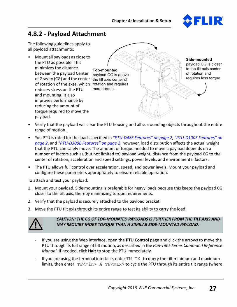
4.8.2 - Payload AttachmentThe following guidelines apply to all payload attachments:
• Mount all payloads as close to the PTU as possible. This minimizes the distance between the payload Center of Gravity (CG) and the center of rotation of the axes, which reduces stress on the PTU and mounting. It also improves performance by reducing the amount of torque required to move the payload.
• Verify that the payload will clear the PTU housing and all surrounding objects throughout the entire range of motion.
• You PTU is rated for the loads specified in “PTU-D48E Features” on page 2, “PTU-D100E Features” on page 2, and “PTU-D300E Features” on page 2; however, load distribution affects the actual weight that the PTU can safely move. The amount of torque needed to move a payload depends on a number of factors such as (but not limited to) payload weight, distance from the payload CG to the center of rotation, acceleration and speed settings, power levels, and environmental factors.
• The PTU allows full control over acceleration, speed, and power levels. Mount your payload and configure these parameters appropriately to ensure reliable operation.
To attach and test your payload:1. Mount your payload. Side mounting is preferable for heavy loads because this keeps the payload CG
closer to the tilt axis, thereby minimizing torque requirements.
2. Verify that the payload is securely attached to the payload bracket.3. Move the PTU tilt axis through its entire range to test its ability to carry the load.
- If you are using the Web interface, open the PTU Control page and click the arrows to move the PTU through its full range of tilt motion, as described in the Pan-Tilt E Series Command Reference Manual. If needed, click Halt to stop the PTU immediately.
- If you are using the terminal interface, enter TN TX to query the tilt minimum and maximum limits, then enter TP<min> A TP<max> to cycle the PTU through its entire tilt range (where
CAUTION: THE CG OF TOP-MOUNTED PAYLOADS IS FURTHER FROM THE TILT AXIS AND MAY REQUIRE MORE TORQUE THAN A SIMILAR SIDE-MOUNTED PAYLOAD.
Side-mounted payload CG is closer to the tilt axis center of rotation and requires less torque.
Top-mounted payload CG is above the tilt axis center of rotation and requires more torque.
Copyright 2016, FLIR Commercial Systems, Inc. 27
PTU-D48, D100, D300 User Manual
<min> is the number returned by the TN query and <max> is the number returned by the TX query). If needed, enter H to stop the PTU immediately.
If the load is too heavy or moving too quickly, the PTU will lose synchronization, which will be audible as a grinding sound from the PTU motors. Stop the test immediately if this occurs, and refer to “Heavy-Payload Operation” on page 34 and “Battery Powered Operation” on page 35. This does not damage the PTU but does indicate that the payload is not mounted and/or the PTU is not configured correctly to move the payload.
4. Move the PTU pan axis through its entire range to test its ability to carry the load.- If you are using the Web interface, open the PTU Control page and click the arrows to move the
PTU through its full range of pan motion, as described in the Pan-Tilt E Series Command Refer-ence Manual. If needed, click Halt to stop the PTU immediately.
- If you are using the terminal interface, enter PN PP to query the pan minimum and maximum limits, then enter PN<min> A PP<max> to cycle the PTU through its entire tilt range (where <min> is the number returned by the PN query and <max> is the number returned by the PX query). If needed, enter H to stop the PTU immediately.
If the load is too heavy or moving too quickly, the PTU will lose synchronization, which will be audible as a grinding sound from the PTU motors. Stop the test immediately if this occurs, and refer to “Heavy-Payload Operation” on page 34 and “Battery Powered Operation” on page 35..
WARNING: STOP THE PTU IMMEDIATELY BY EITHER CLICKING HALT (WEB INTERFACE) OR ISSUING AN H COMMAND (SERIAL INTERFACE) IF THE PAYLOAD IS ABOUT TO COLLIDE WITH THE PTU-E46 AND/OR ANOTHER OBSTACLE. A COLLISION COULD CAUSE A STRUCTURAL FAILURE THAT MAY RESULT IN INJURY OR DEATH.
ISM: Verify that the payload will clear all obstacles when the PTU is in both normal and stabilized modes.
Note: Please refer to “Heavy-Payload Operation” on page 34 for more information on configuring the PTU for heavier payloads.
CAUTION: DO NOT PROCEED BEYOND THIS STEP UNLESS AND UNTIL THE PTU PASSES THE TILT AXIS MOTION TEST.
WARNING: STOP THE PTU IMMEDIATELY BY EITHER CLICKING HALT (WEB INTERFACE) OR ISSUING AN H COMMAND (SERIAL INTERFACE) IF THE PAYLOAD IS ABOUT TO COLLIDE WITH THE PTU AND/OR ANOTHER OBSTACLE. A COLLISION COULD CAUSE A STRUCTURAL FAILURE THAT MAY RESULT IN INJURY OR DEATH.
ISM
Copyright 2016, FLIR Commercial Systems, Inc.28

Chapter 4: Installation & Setup
5. If the PTU passes the above pan and tilt axis load handling tests, you are ready to begin controlling your payload using the commands described in the Pan-Tilt E Series Command Reference Manual.
4.9 - Payload Wiring Connector (Optional for D48E)The PTU provides payload pass-through signals that connect between pins in the base receptacle to corresponding pins in the payload receptacle. Additional pins in the payload receptacle provide other payload controls, including auxiliary RS-232 ports and TTL control. The payload connects to the receptacle via a male MS3126F14-19P plug. “19-Pin Payload Connector” on page A-3 displays this connector and corresponding pin-out.
CAUTION: FOLLOW ALL APPLICABLE SPECIFICATIONS FOR PASS-THROUGH SIGNALS, SUCH AS MAXIMUM VOLTAGE AND CURRENT LEVELS.
Copyright 2016, FLIR Commercial Systems, Inc. 29

PTU-D48, D100, D300 User Manual
This page intentionally left blank.
Copyright 2016, FLIR Commercial Systems, Inc.30
5 - Configuring &Programming
This chapter describes how to configure and program your PTU.
Follow the appropriate instructions to connect the PTU-E46 to the host computer, power it on, and access it via:
• Web: “Ethernet Connection” on page 15.• Serial: “Serial Connection” on page 16.
5.1 - Range of MotionThe PTU range of motion can be limited in the following ways:
• Hard: A hard limit physically cannot be exceeded. A physical pin on the PTU impedes movement.• Factory: Factory limits are smaller than hard limits to prevent physical damage to the PTU and/or
payload.
• User: User limits are programmable limits that are smaller than hard limits and can be as large as factory limits.
The PTU uses high-precision optical limit sensors to determine the limits. It can also be equipped with optional mechanical stops that will limit pan/tilt motion to preset limits. It is possible to set these stops to allow overlapping limits, as shown in the image on the previous page.
Note: You may also have a simultaneous Ethernet connection to the Web interface, as described in “Ethernet Connection” on page 15.
Note: If needed for your application, order optional mechanical stops with your PTU because they are installed during manufacturing.
Copyright 2016, FLIR Commercial Systems, Inc. 31
PTU-D48, D100, D300 User Manual
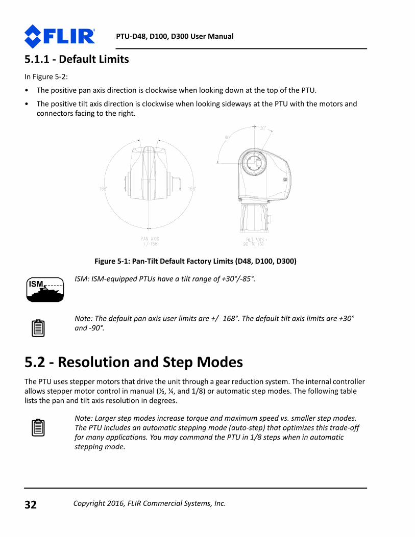
5.1.1 - Default LimitsIn Figure 5-2:• The positive pan axis direction is clockwise when looking down at the top of the PTU.
• The positive tilt axis direction is clockwise when looking sideways at the PTU with the motors and connectors facing to the right.
Figure 5-1: Pan-Tilt Default Factory Limits (D48, D100, D300)
5.2 - Resolution and Step ModesThe PTU uses stepper motors that drive the unit through a gear reduction system. The internal controller allows stepper motor control in manual (½, ¼, and 1/8) or automatic step modes. The following table lists the pan and tilt axis resolution in degrees.
ISM: ISM-equipped PTUs have a tilt range of +30°/-85°.
Note: The default pan axis user limits are +/- 168°. The default tilt axis limits are +30° and -90°.
Note: Larger step modes increase torque and maximum speed vs. smaller step modes. The PTU includes an automatic stepping mode (auto-step) that optimizes this trade-off for many applications. You may command the PTU in 1/8 steps when in automatic stepping mode.
ISM
Copyright 2016, FLIR Commercial Systems, Inc.32
Chapter 5: Configuring & Programming
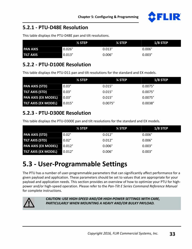
5.2.1 - PTU-D48E ResolutionThis table displays the PTU-D48E pan and tilt resolutions.
5.2.2 - PTU-D100E ResolutionThis table displays the PTU-D11 pan and tilt resolutions for the standard and EX models.
5.2.3 - PTU-D300E ResolutionThis table displays the PTU-D300E pan and tilt resolutions for the standard and EX models.
5.3 - User-Programmable SettingsThe PTU has a number of user-programmable parameters that can significantly affect performance for a given payload and application. These parameters should be set to values that are appropriate for your payload and application needs. This section provides an overview of how to optimize your PTU for high-power and/or high-speed operation. Please refer to the Pan-Tilt E Series Command Reference Manual for complete instructions.
½ STEP ¼ STEP 1/8 STEPPAN AXIS 0.026° 0.013° 0.006°TILT AXIS 0.013° 0.006° 0.003°
½ STEP ¼ STEP 1/8 STEPPAN AXIS (STD) 0.03° 0.015° 0.0075°TILT AXIS (STD) 0.03° 0.015° 0.0075°PAN AXIS (EX MODEL) 0.03° 0.015° 0.0075°TILT AXIS (EX MODEL) 0.015° 0.0075° 0.0038°
½ STEP ¼ STEP 1/8 STEPPAN AXIS (STD) 0.02° 0.012° 0.006°TILT AXIS (STD) 0.02° 0.012° 0.006°PAN AXIS (EX MODEL) 0.012° 0.006° 0.003°TILT AXIS (EX MODEL) 0.012° 0.006° 0.003°
CAUTION: USE HIGH-SPEED AND/OR HIGH-POWER SETTINGS WITH CARE, PARTICULARLY WHEN MOUNTING A HEAVY AND/OR BULKY PAYLOAD.
Copyright 2016, FLIR Commercial Systems, Inc. 33
PTU-D48, D100, D300 User Manual
5.3.1 - High-Speed Operation The following factors should be considered when planning high speed operation:• Load weight, weight distribution, and dynamics.
- Move the payload as close to the axis centers of rotation as possible. Doing this will reduce the torque required to move the payload and allow a higher top speed.
- Balancing the load, such as by using a counterweight or splitting the payload into two pieces can also help significantly.
• Desired upper speed limit.• Rate of acceleration.
• The base (start-up) speed.• Power supply voltage. Higher voltages within the permissible range significantly improve axis speed
and acceleration performance.
• In-motion power modes. If the duty cycle is less than 20%, you may use high move power to increase the top speed.
• Multi-axis dynamics. Simultaneously moving the tilt and pan axes affects the forces exerted on the PTU.
• Always begin high-speed tests on each axis in isolation. Only perform simultaneous pan-tilt movements once each individual axis is optimized.
• The base speed is the PTU minimum speed. In practice, the unit will instantly accelerate to this speed. Setting a base speed can help speed up movement by eliminating a segment of acceleration time.
• Aggressive acceleration settings with heavy payloads can cause increased wear on the PTU.An example configuration string for high speed operations is:PA9000 PU6000 TA9000 PU6000 DS
5.3.2 - Heavy-Payload OperationIf the PTU fails the initial load handling tests, you may be able to program it for higher-power operations. The speed and acceleration of a mechanical system depend on the inertial properties of the payload. The ability of the PTU to successfully move the payload without losing synchronization depends upon the inertial payload factors and their relationship to power supply voltage, unit speed, acceleration, position, motor torque, etc.
WARNING: FAILURE TO ADEQUATELY SECURE THE PTU TO A MOUNTING THAT CAN WITHSTAND THE FORCES APPLIED BY BOTH HIGH-SPEED, HIGH-POWER MOVEMENT AND ENVIRONMENTAL FASCTORS SUCH AS VEHICLE MOVEMENT OR WIND CAN CAUSE A STRUCTURAL FAILURE RESULTING IN INJURY OR DEATH
Copyright 2016, FLIR Commercial Systems, Inc.34

Chapter 5: Configuring & Programming
To increase payload capacity:Configure the PTU for increased motor current and torque. If your move duty cycle is less than 20%, you can set the Move Power to High (Web) or use the following serial commands: PMH TMH PHR THR.You may also:
• Move the payload CG closer to the PTU tilt axis. See “Payload Attachment” on page 27.• Use a higher-voltage power source in the permissible range• Determine if the payload can be modified to lighten it.
• Set the base speed to 0.• If the PTU is having trouble resetting the tilt axis, try using user limits to reduce the tilt-axis range of
motion.
• Reduce speed and/or acceleration.Please refer to the Pan-Tilt E Series Command Reference Manual for more information.
5.3.3 - Battery Powered OperationThe PTU can be battery powered. Battery-powered applications must conserve as much power as possible. The PTU includes commands that control pan-tilt motor power consumption both while moving and when stopped. Please refer to the Pan-Tilt E Series Command Reference Manual for more information.
CAUTION: ALWAYS USE A FUSE WHEN CONNECTING THE PTU TO A BATTERY.
Copyright 2016, FLIR Commercial Systems, Inc. 35

PTU-D48, D100, D300 User Manual
This page intentionally left blank.
Copyright 2016, FLIR Commercial Systems, Inc.36

A - Electrical Specifications
This Appendix describes the PL01 and PL02 wiring options for the PTU. Please refer to the appropriate section for your unit, and to “Mechanical Overview” on page 20 for a mechanical overview.
In general:
• TX lines carry data from the PTU-D300E.• RX lines carry data to the PTU-D300E.
CAUTION: DO NOT EXCEED MAXIMUM RATED PASS-THROUGH AMPERAGES. FUSE PAYLOADS AT RATED TRIP VALUES. THE PTU-D300E WARRANTY DOES NOT COVER DAMAGE CAUSED BY OVERCURRENT SITUATIONS.
CAUTION: ALWAYS TERMINATE THE SHIELD LINE TO AN APPROPRIATE SYSTEM SHIELD OR GROUND CONNECTION.
ISM: ISM-equipped PTUs are equipped with the PL02 wiring option.ISM
Copyright 2016, FLIR Commercial Systems, Inc. A-1
PTU-D48, D100, D300 User Manual
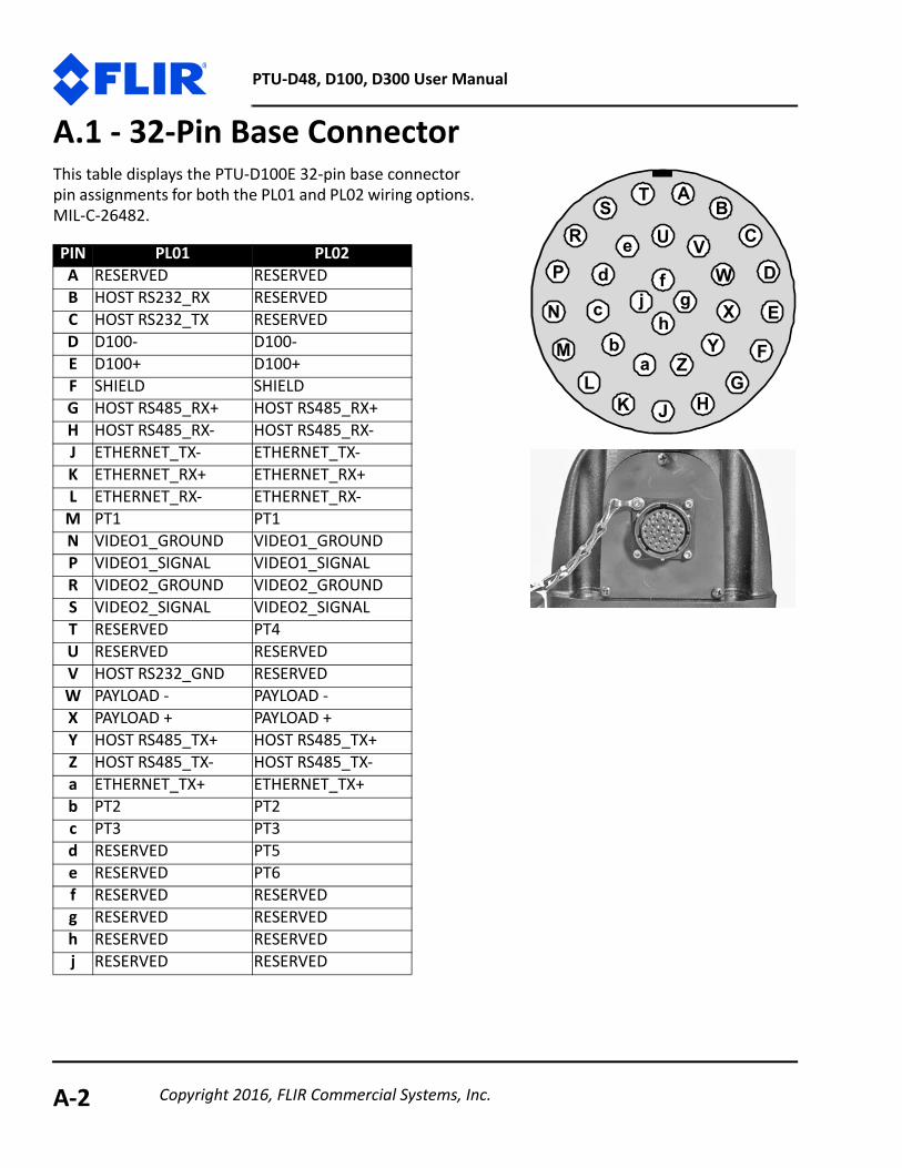
A.1 - 32-Pin Base ConnectorThis table displays the PTU-D100E 32-pin base connector pin assignments for both the PL01 and PL02 wiring options. MIL-C-26482.
PIN PL01 PL02A RESERVED RESERVEDB HOST RS232_RX RESERVEDC HOST RS232_TX RESERVEDD D100- D100-E D100+ D100+F SHIELD SHIELDG HOST RS485_RX+ HOST RS485_RX+H HOST RS485_RX- HOST RS485_RX-J ETHERNET_TX- ETHERNET_TX-K ETHERNET_RX+ ETHERNET_RX+L ETHERNET_RX- ETHERNET_RX-
M PT1 PT1N VIDEO1_GROUND VIDEO1_GROUNDP VIDEO1_SIGNAL VIDEO1_SIGNALR VIDEO2_GROUND VIDEO2_GROUNDS VIDEO2_SIGNAL VIDEO2_SIGNALT RESERVED PT4U RESERVED RESERVEDV HOST RS232_GND RESERVEDW PAYLOAD - PAYLOAD -X PAYLOAD + PAYLOAD +Y HOST RS485_TX+ HOST RS485_TX+Z HOST RS485_TX- HOST RS485_TX-a ETHERNET_TX+ ETHERNET_TX+b PT2 PT2c PT3 PT3d RESERVED PT5e RESERVED PT6f RESERVED RESERVEDg RESERVED RESERVEDh RESERVED RESERVEDj RESERVED RESERVED
TS
R
AB
C
E
GK
L
M
N
P W
Zb
c
d fgj X
U VD
Y
HJ
h
e
a F
Copyright 2016, FLIR Commercial Systems, Inc.A-2

Appendix A: Electrical Specifications
A.2 - 19-Pin Payload ConnectorThis table displays the PTU-D100E 19-pin payload connector pin assignments for both the PL01 and PL02 wiring options. MIL-C-26402.
PIN PL01 PL02A CHA_RX HOST_RS232_TXB CHA_TX HOST_RS232_RXC CHB_RX TTL_OP2D CHB_TX TTL_OP3E CHB_DTR TTL_OP4F SHIELD SHIELDG VIDEO1_GROUND VIDEO1_GROUNDH VIDEO1_SIGNAL VIDEO1_SIGNALJ TTL_OP2 PT4K CHA_TTL_RX PT5L CHA_TTL_TX PT6
M RS232_GND HOST_RS232_GNDN PT3 PT3P PT2 PT2R PAYLOAD - PAYLOAD -S PAYLOAD + PAYLOAD +T VIDEO2_SIGNAL VIDEO2_SIGNALU VIDEO2_GROUND VIDEO2_GROUNDV PT1 PT1
C
D
EJ
K
N P
R
ST
U V
A BM
L
FGH
Copyright 2016, FLIR Commercial Systems, Inc. A-3
PTU-D48, D100, D300 User Manual
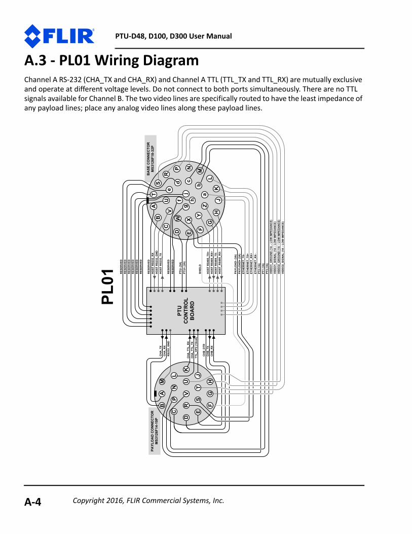
A.3 - PL01 Wiring DiagramChannel A RS-232 (CHA_TX and CHA_RX) and Channel A TTL (TTL_TX and TTL_RX) are mutually exclusive and operate at different voltage levels. Do not connect to both ports simultaneously. There are no TTL signals available for Channel B. The two video lines are specifically routed to have the least impedance of any payload lines; place any analog video lines along these payload lines.
PAYL
OA
DC
ON
NEC
TOR
MS3
126F
14-1
9P
BA
SEC
ON
NEC
TOR
MS3
126F
18-3
2PT
A
E
M
W
b
cdf
gj
C
D
EJ
K
NP
R
ST
UV
X
PL01
PTU
CO
NTR
OL
BO
AR
D
UV
D
HJh
eA
B
VID
EO1_
GR
OU
ND
(1A
–LO
WIM
PED
AN
CE)
VID
EO1_
SIG
NA
L(1
A–
LOW
IMPE
DA
NC
E)VI
DEO
2_G
RO
UN
D(1
A–
LOW
IMPE
DA
NC
E)VI
DEO
2_SI
GN
AL
(1A
–LO
WIM
PED
AN
CE)
HO
STR
S232
_GN
DH
OST
RS2
32_T
X
HO
STR
S232
_RX
HO
STR
S485
_RX+
HO
ST_R
S485
_RX-
HO
STR
S485
_TX+
HO
STR
S485
_TX-
SHIE
LD
a
ETH
ERN
ET_T
X-ET
HER
NET
_TX+
ETH
ERN
ET_R
X+ET
HER
NET
_RX-
PT2
(1A
)PT
1(1
A)
PT3
(1A
)
PTU
-(3A
)PT
U+
(3A
)
PAYL
OA
D-(
3A)
PAYL
OA
D+
(3A
)
RES
ERVE
D
RES
ERVE
D
RES
ERVE
DR
ESER
VED
RES
ERVE
DR
ESER
VED
RES
ERVE
DR
ESER
VED
RES
ERVE
D
CH
A_T
XC
HA
_RX
TTL_
OP2
(10m
A)
CH
A_T
TL_R
XC
HA
_TTL
_TX
CH
B_D
TRC
HB
_TX
CH
B_R
X
F
RS2
32_G
ND
L
FG
HG
KL
ZY
NP
SR
BC
M
Copyright 2016, FLIR Commercial Systems, Inc.A-4
Appendix A: Electrical Specifications
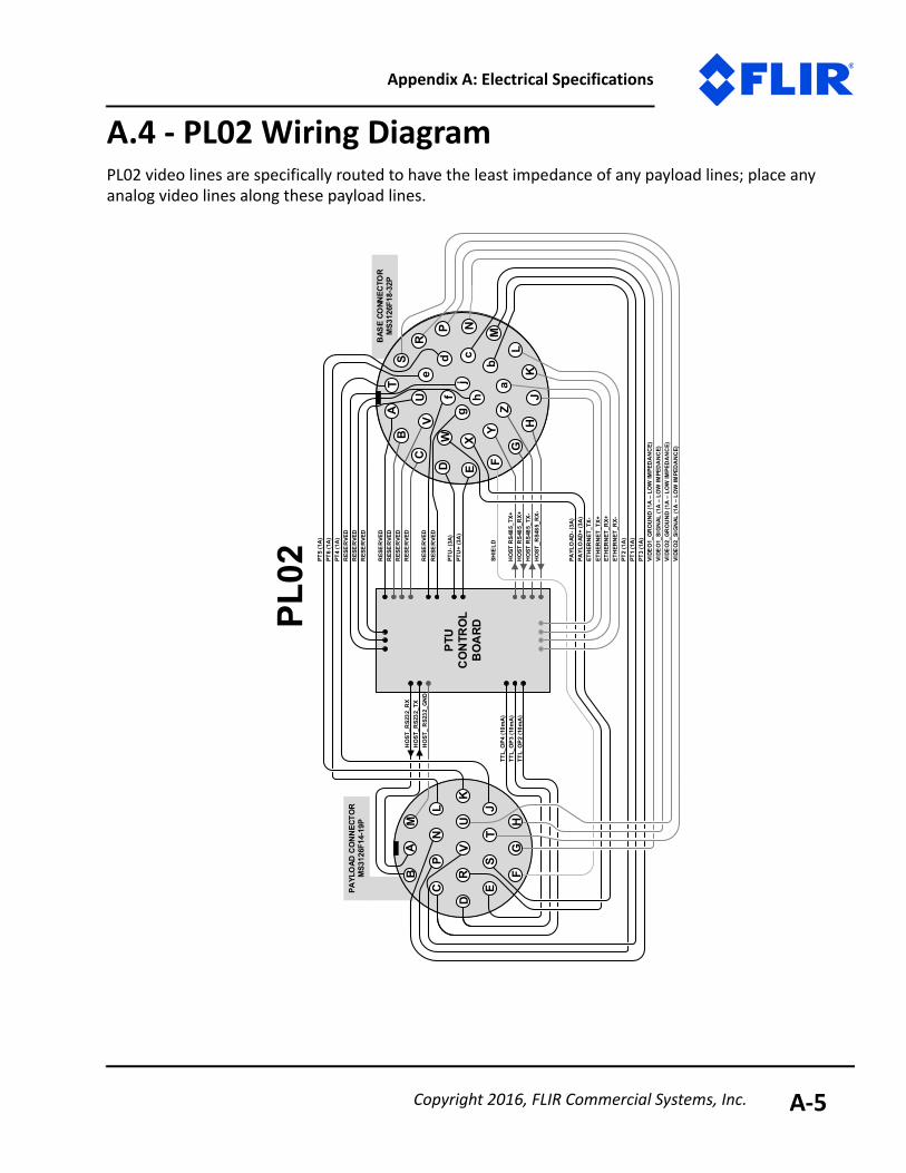
A.4 - PL02 Wiring DiagramPL02 video lines are specifically routed to have the least impedance of any payload lines; place any analog video lines along these payload lines.
PAYL
OAD
CO
NN
ECTO
RM
S312
6F14
-19P
BAS
E CO
NNEC
TOR
MS3
126F
18-3
2PT
A
E
M
W
cdf
gj
C
D
EJ
K
P
R
ST
UV
X
PL02
PTU
CO
NTR
OL
BO
ARD
UV
D
HJh
eA
B
VIDE
O1_
GR
OU
ND
(1A
– L
OW
IMPE
DA
NC
E)VI
DEO
1_SI
GN
AL (1
A –
LO
W IM
PED
AN
CE)
VIDE
O2_
GR
OU
ND
(1A
– L
OW
IMPE
DA
NC
E)VI
DEO
2_SI
GN
AL (1
A –
LO
W IM
PED
AN
CE)
RES
ER
VED
RES
ER
VED
RES
ER
VED
HO
ST R
S485
_RX+
HO
ST_R
S485
_RX-
HO
ST R
S485
_TX+
HO
ST R
S485
_TX-
SHIE
LD
a
ETH
ERN
ET_T
X-ET
HER
NET
_TX+
ETH
ERN
ET_R
X+ET
HER
NET
_RX-
PT2
(1A
)PT
1 (1
A)
PT3
(1A
)
PTU
- (3A
)PT
U+
(3A
)
PAYL
OAD
- (3A
)PA
YLO
AD+
(3A
)
RES
ER
VED
PT4
(1A
)
PT5
(1A
)PT
6 (1
A)
RES
ER
VED
RES
ER
VED
RES
ER
VED
RES
ER
VED
RES
ER
VED
HO
ST_R
S232
_TX
HO
ST_R
S232
_RX
TTL_
OP4
(10m
A)
TTL_
OP3
(10m
A)
TTL_
OP2
(10m
A)
F
HO
ST_
RS2
32_G
ND
L
FG
H
N
MB
CS
R
P N
L
b K
ZG
Y
Copyright 2016, FLIR Commercial Systems, Inc. A-5
PTU-D48, D100, D300 User Manual
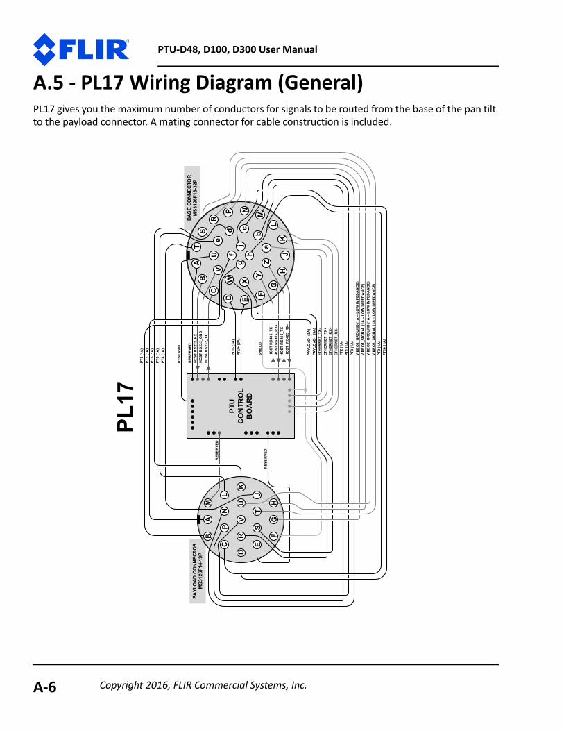
A.5 - PL17 Wiring Diagram (General)PL17 gives you the maximum number of conductors for signals to be routed from the base of the pan tilt to the payload connector. A mating connector for cable construction is included.
PAYL
OAD
CO
NN
ECTO
RM
S312
6F14
-19P
BAS
E CO
NNEC
TOR
MS3
126F
18-3
2PT
A
E
M
W
cdj
C
D
E
K
NP
R
ST
UV
X
PL17
PTU
CO
NTR
OL
BO
ARD
UV
D
HJh
eB
VIDE
O1_
GR
OU
ND
(1A
– L
OW
IMPE
DA
NC
E)VI
DEO
1_SI
GN
AL (1
A –
LO
W IM
PED
AN
CE)
VIDE
O2_
GR
OU
ND
(1A
– L
OW
IMPE
DA
NC
E)VI
DEO
2_SI
GN
AL (1
A –
LO
W IM
PED
AN
CE)
HO
ST R
S232
_GN
DH
OST
RS2
32_T
X
HO
ST R
S232
_RX
HO
ST R
S485
_RX+
HO
ST_R
S485
_RX-
HO
ST R
S485
_TX+
HO
ST R
S485
_TX-
SHIE
LD
a
ETH
ERN
ET_T
X-ET
HER
NET
_TX+
ETH
ERN
ET_R
X+ET
HER
NET
_RX-
PT2
(1A
)PT
1 (1
A)
PT3
(1A
)
PTU
- (3A
)PT
U+
(3A
)
PAYL
OAD
- (3A
)PA
YLO
AD+
(3A
)
RES
ER
VED
PT4
(1A
)
PT5
(1A
)PT
6 (1
A)
RES
ER
VED
RES
ER
VED
F
RES
ER
VED
L
FG
HG
KL
ZY
NP
SR
BC
M
Jb
PT7
(1A
)
f
A
g
PT8
(1A
)
PT9
(1A
)PT
10 (1
A)
Copyright 2016, FLIR Commercial Systems, Inc.A-6

Appendix A: Electrical Specifications
A.6 - PL17 Wiring Diagram(PTU-D100E with Slip Ring Only)PL17 gives you the maximum number of conductors for signals to be routed from the base of the pan tilt to the payload connector. A mating connector for cable construction is included.
PTU
CO
NTR
OL
BO
ARD
PAYL
OAD
CO
NN
ECTO
RM
S312
6F14
-19P
BAS
E CO
NNEC
TOR
MS3
126F
18-3
2PT
A
E
M
W
cdj
C
D
E
K
NP
R
ST
UV
X
PL17
UV
D
HJh
eB
VIDE
O1_
GR
OU
ND
(1A
– L
OW
IMPE
DA
NC
E)VI
DEO
1_SI
GN
AL (1
A –
LO
W IM
PED
AN
CE)
VIDE
O2_
GR
OU
ND
(1A
– L
OW
IMPE
DA
NC
E)VI
DEO
2_SI
GN
AL (1
A –
LO
W IM
PED
AN
CE)
HO
ST R
S232
_GN
DH
OST
RS2
32_T
X
HO
ST R
S232
_RX
HO
ST R
S485
_RX+
HO
ST_R
S485
_RX-
HO
ST R
S485
_TX+
HO
ST R
S485
_TX-
SHIE
LD
a
ETH
ERN
ET_T
X-ET
HER
NET
_TX+
ETH
ERN
ET_R
X+ET
HER
NET
_RX-
PT2
(1A
)PT
1 (1
A)
PT3
(1A
)
PTU
- (3A
)PT
U+
(3A
)
PAYL
OAD
- (3A
)PA
YLO
AD+
(3A
)
RES
ER
VED
PT4
(1A
)
PT5
(1A
)PT
6 (1
A)
RES
ER
VED
RES
ER
VED
F
RES
ER
VED
L
FG
HG
KL
ZY
NP
SR
BC
M
Jb
PT7
(1A
– E
THER
NET
10/
100B
T)
f
A
g
PT8
(1A
– E
THER
NET
10/
100B
T)
PT9
(1A
– E
THER
NET
10/
100B
T)PT
10 (1
A –
ETH
ERN
ET 1
0/10
0BT)
For t
he P
TU-D
100E
with
10
0Bas
eT s
lip ri
ng o
ptio
n
Copyright 2016, FLIR Commercial Systems, Inc. A-7
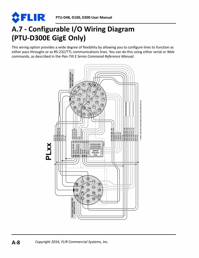
PTU-D48, D100, D300 User Manual
A.7 - Configurable I/O Wiring Diagram(PTU-D300E GigE Only)This wiring option provides a wide degree of flexibility by allowing you to configure lines to function as either pass-throughs or as RS-232/TTL communications lines. You can do this using either serial or Web commands, as described in the Pan-Tilt E Series Command Reference Manual.
PAYL
OAD
CO
NN
ECTO
RM
S312
6F14
-19P
BAS
E CO
NNEC
TOR
MS3
126F
18-3
2PT
A
E
M
W
cdj
C
D
NP
R
ST
UV
X
PLxx
UV
D
HJh
eB
aF
FH
GK
LZ
Y
NP
SR
BC
M
Jb
PT15
* (1A
)
f
A
gK
L
E
G
PT16
* (1A
)H
IGH
SPE
ED
PT7*
1A
)H
IGH
SPE
ED
PT8*
(1A
)PT
14* (
1A)
PT10
* (1A
)PT
9* (1
A)
PAYL
OAD
PW
R –
(3A
)
PT13
* (1A
)
PAYL
OAD
PW
R +
(3A
)
HIG
H S
PEE
D PT
5* (1
A)
HIG
H S
PEE
D PT
6* (1
A)
HIG
H S
PEE
D PT
1* (1
A)
HIG
H S
PEE
D PT
2* (1
A)
HIG
H S
PEE
D PT
3* (1
A)
HIG
H S
PEE
D PT
4* (1
A)
PT12
* (1A
)PT
11* (
1A)
SIG
NAL
GRO
UND
CH
A TX
HO
ST R
S-23
2 TX
HO
ST R
S-23
2 R
XC
HB
DTR
CH
A RX
CH
B RX
CH
B TX
HO
ST R
S-23
2 R
XH
OST
RS-
232
GN
DH
OST
RS-
232
TXPT
U-
PTU
+H
OST
RS-
485
TX+
HOST RS-485 RX+HOST RS-485 TX-HOST RS-485 RX-
ETH
ERN
ET T
X-ET
HER
NET
TX+
ETH
ERN
ET R
X+ET
HER
NET
RX-
PTU CONTROL
BOARD
SHIE
LD
SHIE
LD
* = T
HES
E L
INES
AR
E C
ON
FIG
URA
BLE
AN
D C
AN
BE S
WIT
CHE
D O
FF.
Copyright 2016, FLIR Commercial Systems, Inc.A-8
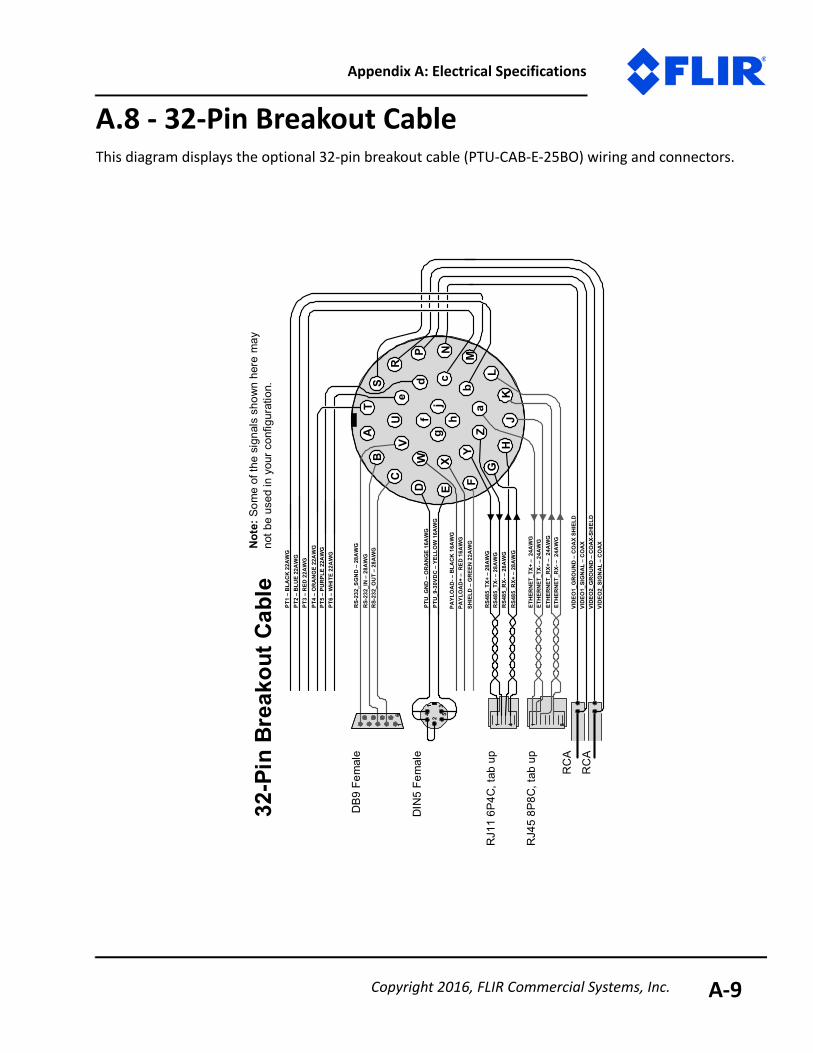
Appendix A: Electrical Specifications
A.8 - 32-Pin Breakout CableThis diagram displays the optional 32-pin breakout cable (PTU-CAB-E-25BO) wiring and connectors.
TA
E
M
W
b
cdf
gj
X
U
D
HJh
VID
EO1_
GR
OU
ND
–C
OA
X S
HIEL
DVI
DEO
1_SI
GN
AL –
CO
AXVI
DEO
2_G
RO
UN
D –
CO
AX-
SHIE
LDVI
DEO
2_SI
GN
AL –
CO
AX
RS-
232_
SGN
D –
28A
WG
RS-
232_
OU
T –
28A
WG
RS-
232_
IN –
28A
WG
RS4
85_R
X-–
28A
WG
RS4
85_R
X+ –
28A
WG
RS4
85_T
X+ –
28A
WG
RS4
85_T
X-–
28A
WG
SHIE
LD –
GRE
EN 2
2AW
G
a
ETH
ERNE
T_TX
+ –
24A
WG
ETH
ERN
ET_T
X-–
24A
WG
ETH
ERN
ET_R
X+ –
24A
WG
ETH
ERN
ET_R
X-–
24A
WG
PT1
–B
LAC
K 2
2AW
GPT
2 –
BLU
E 2
2AW
GPT
3 –
RED
22A
WG
PTU
_GN
D –
OR
AN
GE
16A
WG
PTU
_9-3
0VD
C –
YELL
OW
16A
WG
PAYL
OA
D-–
BLA
CK
16A
WG
PAYL
OA
D+
–R
ED 1
6AW
G
PT4
–O
RA
NG
E 2
2AW
GPT
5 –
PUR
PLE
22A
WG
PT6
–W
HITE
22A
WG
F
GK
LZ
Y
NP
SR
B
1V
C6
DB9
Fem
ale
35
14
2
DIN
5 Fe
mal
e
RC
A
RC
A
1 4
RJ1
1 6P
4C, t
ab u
p
1 8
RJ4
5 8P
8C, t
ab u
p
32-P
in B
reak
out C
able
e
Note
: Som
e of
the
sign
als
show
n h
ere
may
no
t be
used
in yo
ur co
nfig
urat
ion.
Copyright 2016, FLIR Commercial Systems, Inc. A-9

PTU-D48, D100, D300 User Manual
This page intentionally left blank.
Copyright 2016, FLIR Commercial Systems, Inc.A-10
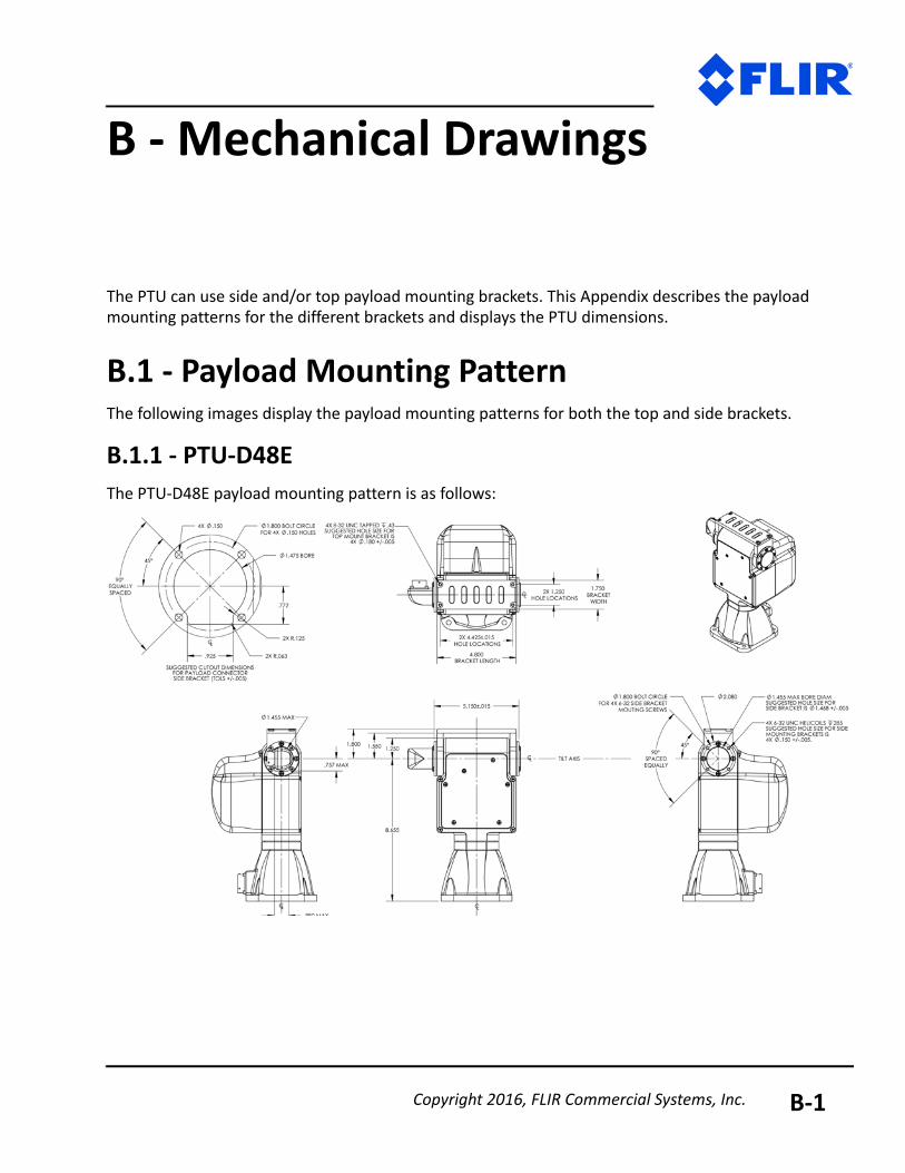
B - Mechanical Drawings
The PTU can use side and/or top payload mounting brackets. This Appendix describes the payload mounting patterns for the different brackets and displays the PTU dimensions.
B.1 - Payload Mounting PatternThe following images display the payload mounting patterns for both the top and side brackets.
B.1.1 - PTU-D48EThe PTU-D48E payload mounting pattern is as follows:
Copyright 2016, FLIR Commercial Systems, Inc. B-1
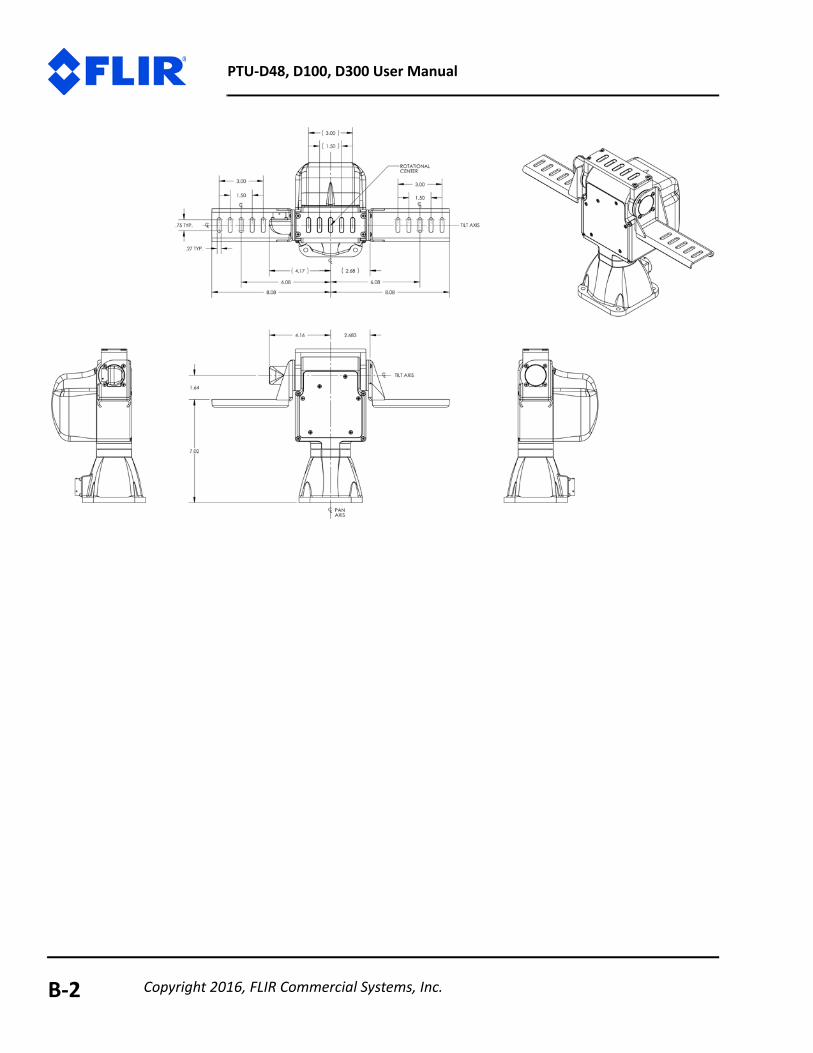
PTU-D48, D100, D300 User Manual
Copyright 2016, FLIR Commercial Systems, Inc.B-2

Appendix B: Mechanical Drawings
B.1.2 - PTU-D100EThe PTU-D100E payload mounting pattern is as follows:
Copyright 2016, FLIR Commercial Systems, Inc. B-3
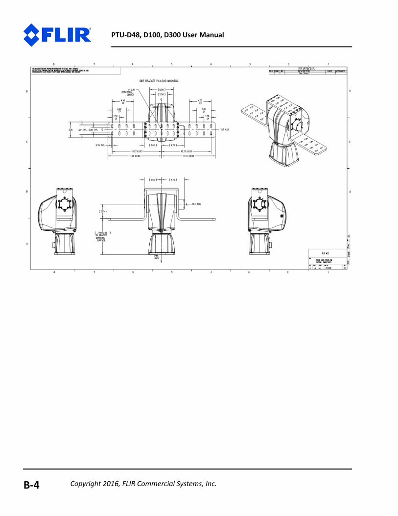
PTU-D48, D100, D300 User Manual
Copyright 2016, FLIR Commercial Systems, Inc.B-4
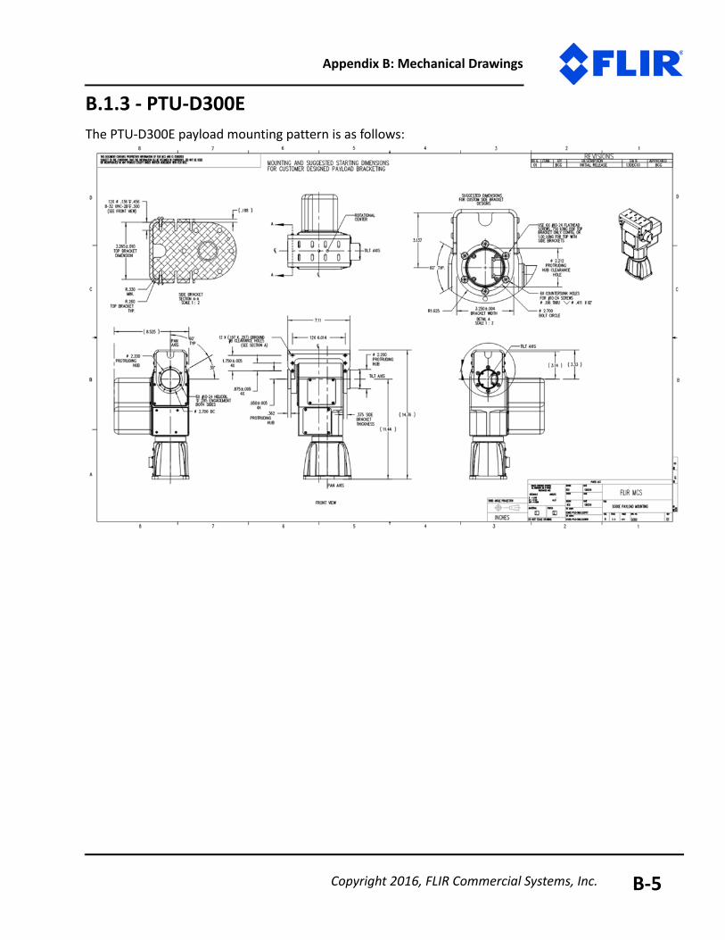
Appendix B: Mechanical Drawings
B.1.3 - PTU-D300EThe PTU-D300E payload mounting pattern is as follows:
Copyright 2016, FLIR Commercial Systems, Inc. B-5

PTU-D48, D100, D300 User Manual
Copyright 2016, FLIR Commercial Systems, Inc.B-6
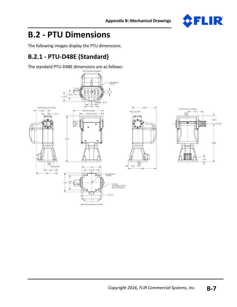
Appendix B: Mechanical Drawings
B.2 - PTU DimensionsThe following images display the PTU dimensions.
B.2.1 - PTU-D48E (Standard)The standard PTU-D48E dimensions are as follows:
Copyright 2016, FLIR Commercial Systems, Inc. B-7
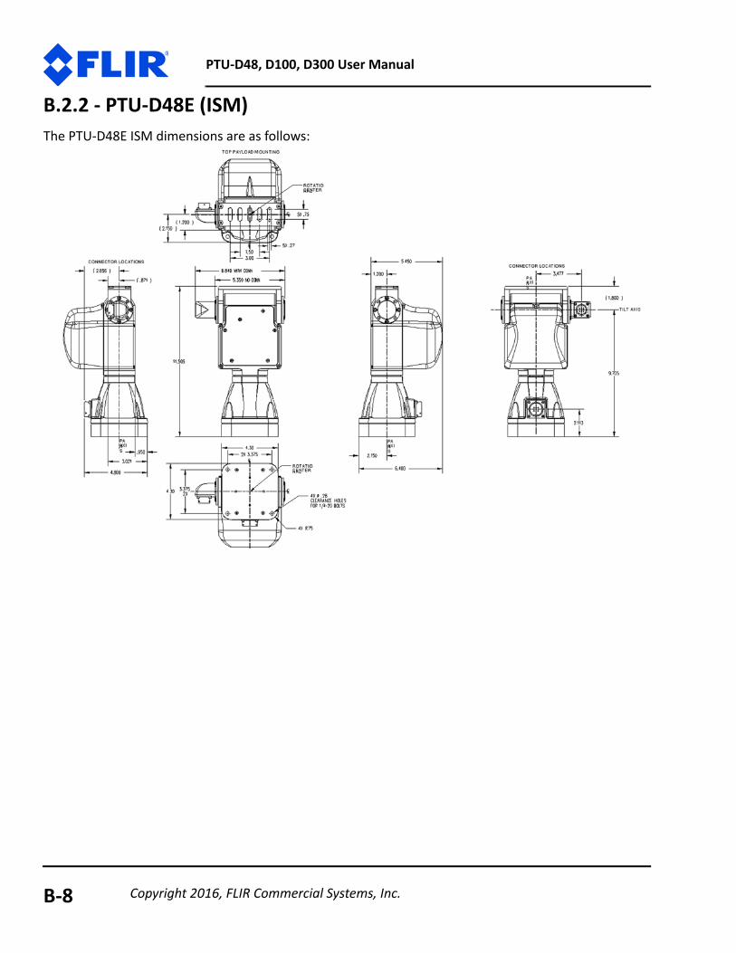
PTU-D48, D100, D300 User Manual
B.2.2 - PTU-D48E (ISM)The PTU-D48E ISM dimensions are as follows:
Copyright 2016, FLIR Commercial Systems, Inc.B-8
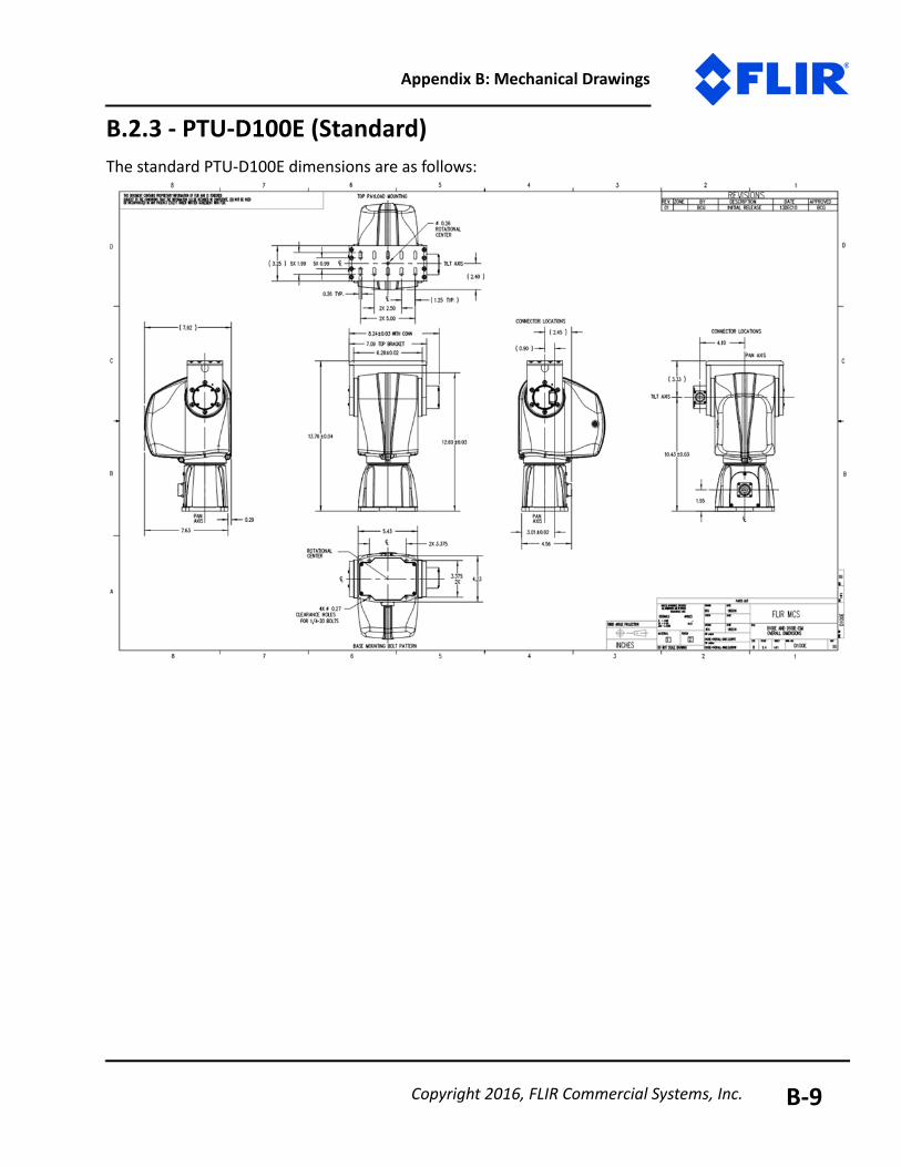
Appendix B: Mechanical Drawings
B.2.3 - PTU-D100E (Standard)The standard PTU-D100E dimensions are as follows:
Copyright 2016, FLIR Commercial Systems, Inc. B-9
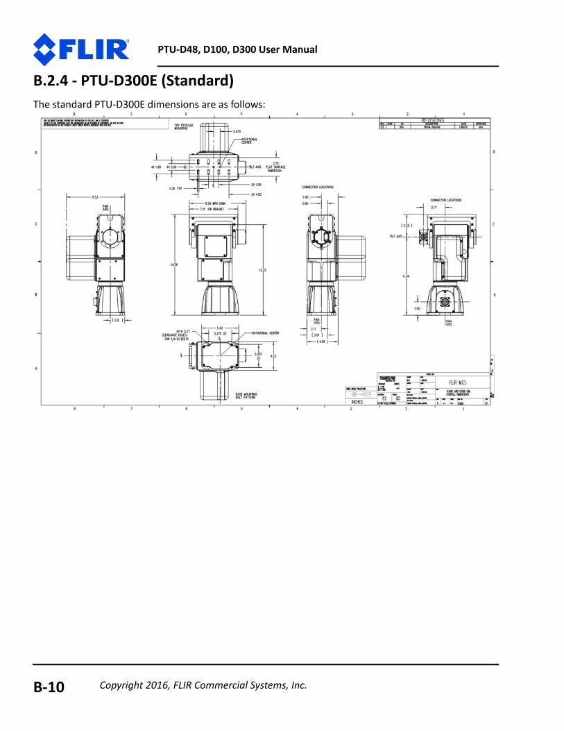
PTU-D48, D100, D300 User Manual
B.2.4 - PTU-D300E (Standard)The standard PTU-D300E dimensions are as follows:
Copyright 2016, FLIR Commercial Systems, Inc.B-10
C - Networking
This section describes the basic installation and setup steps required to network your pan-tilt units.
C.1 - EthernetTo connect multiple PTU units to a single host computer via Ethernet:
1. Plan the physical placement of each PTU and the host computer.2. Connect each PTU to your network using the Ethernet connection on each unit.3. On the host computer, run the PTU Finder utility to locate the PTU IP addresses.
4. Launch a Web browser and point it to the IP address of the unit you want to connect to. You may open multiple browser windows/tabs to connect to multiple units at once.
Please see “Ethernet Connection” on page 15 for more information about connecting to a PTU using the Web interface.
C.2 - SerialYou may connect up to 127 PTUs to a single host computer port. The host computer can then address each connected PTU as if it were the only unit on the network. This makes it easy to migrate code developed for a single PTU to a network of PTUs controlled by one host computer.To connect multiple PTU units to a single host computer via serial:1. Assign a unique network ID number to each PTU.
2. Connect the PTU units and host computer to the serial network.3. Test the configuration by addressing each PTU by its unit ID and issuing commands and queries.
Copyright 2016, FLIR Commercial Systems, Inc. C-1
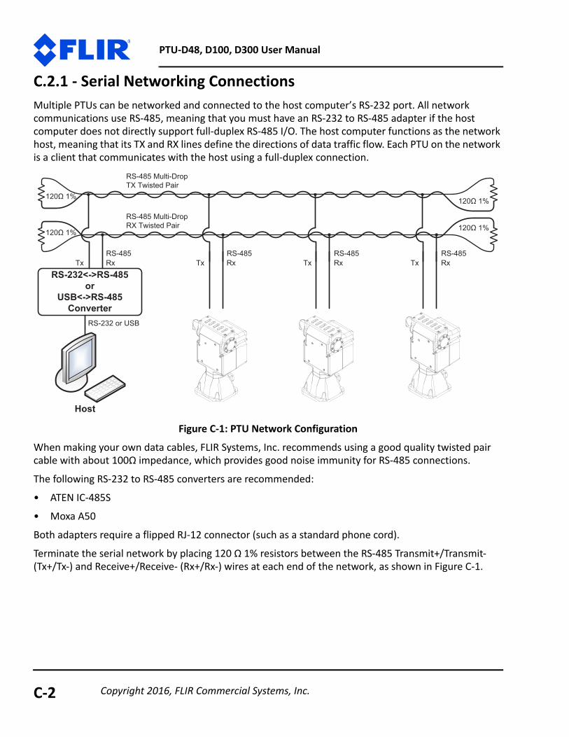
PTU-D48, D100, D300 User Manual
C.2.1 - Serial Networking ConnectionsMultiple PTUs can be networked and connected to the host computer’s RS-232 port. All network communications use RS-485, meaning that you must have an RS-232 to RS-485 adapter if the host computer does not directly support full-duplex RS-485 I/O. The host computer functions as the network host, meaning that its TX and RX lines define the directions of data traffic flow. Each PTU on the network is a client that communicates with the host using a full-duplex connection.
Figure C-1: PTU Network ConfigurationWhen making your own data cables, FLIR Systems, Inc. recommends using a good quality twisted pair cable with about 100Ω impedance, which provides good noise immunity for RS-485 connections.
The following RS-232 to RS-485 converters are recommended:• ATEN IC-485S• Moxa A50
Both adapters require a flipped RJ-12 connector (such as a standard phone cord).Terminate the serial network by placing 120 Ω 1% resistors between the RS-485 Transmit+/Transmit- (Tx+/Tx-) and Receive+/Receive- (Rx+/Rx-) wires at each end of the network, as shown in Figure C-1.
RS-232<->RS-485or
USB<->RS-485Converter
Host
RS-232 or USB
xRxTxRxTxRxTxRxT584-SR584-SR584-SR584-SR
RS-485 Multi-Drop TX Twisted Pair
RS-485 Multi-Drop RX Twisted Pair
120 1%
120 1%
120 1%
120 1%
Copyright 2016, FLIR Commercial Systems, Inc.C-2

Appendix C: Networking
C.2.2 - ASCII Command SyntaxThis section provides a brief overview of the ASCII command syntax. Please refer to the Pan-Tilt E Series Command Reference Manual for complete information and instructions.
The PTU uses both commands and queries. A command tells the PTU to do something (such as pan to a specific angle). A query asks the PTU to return the requested value (such as reporting the current pan angle).
The basic ASCII command syntax is <command><parameter><delimiter>, where:• <command> is the actual command (such as PP for pan position), • <parameter> is a numerical value (such as the desired pan position), and
• <delimiter> is a character used to denote the end of a command. Valid delimiter characters can be either [SPACE] or [ENTER].
The basic ASCII query syntax is <command><delimiter>, where:
• <command> is the actual command (such as PP for pan position), • <delimiter> is a character used to denote the end of a query. Valid delimiter characters can be
either [SPACE] or [ENTER].
For example:• Command: PP<position><delim> sets the desired absolute pan position.• Query: PP<delim> returns the current absolute pan position.
Commands and queries return results that display on the terminal screen, as follows:• A successfully executed command displays * on the terminal screen.• A successfully executed query displays <QueryResult> (where <QueryResult> is the result
of the query you just executed).• A failed command displays! <ErrorMessage> (where <ErrorMessage> describes the error
encountered).
• A pan axis limit hit asynchronously displays !P.• A tilt axis limit hit asynchronously displays !T.This sample command sequence pans the PTU-E46 to the left, waits, and then pans it back to the right:
SPP-2500 *A *PP * Current Pan position is -2500PP2500 *A *PP * Current Pan position is 2500
Copyright 2016, FLIR Commercial Systems, Inc. C-3
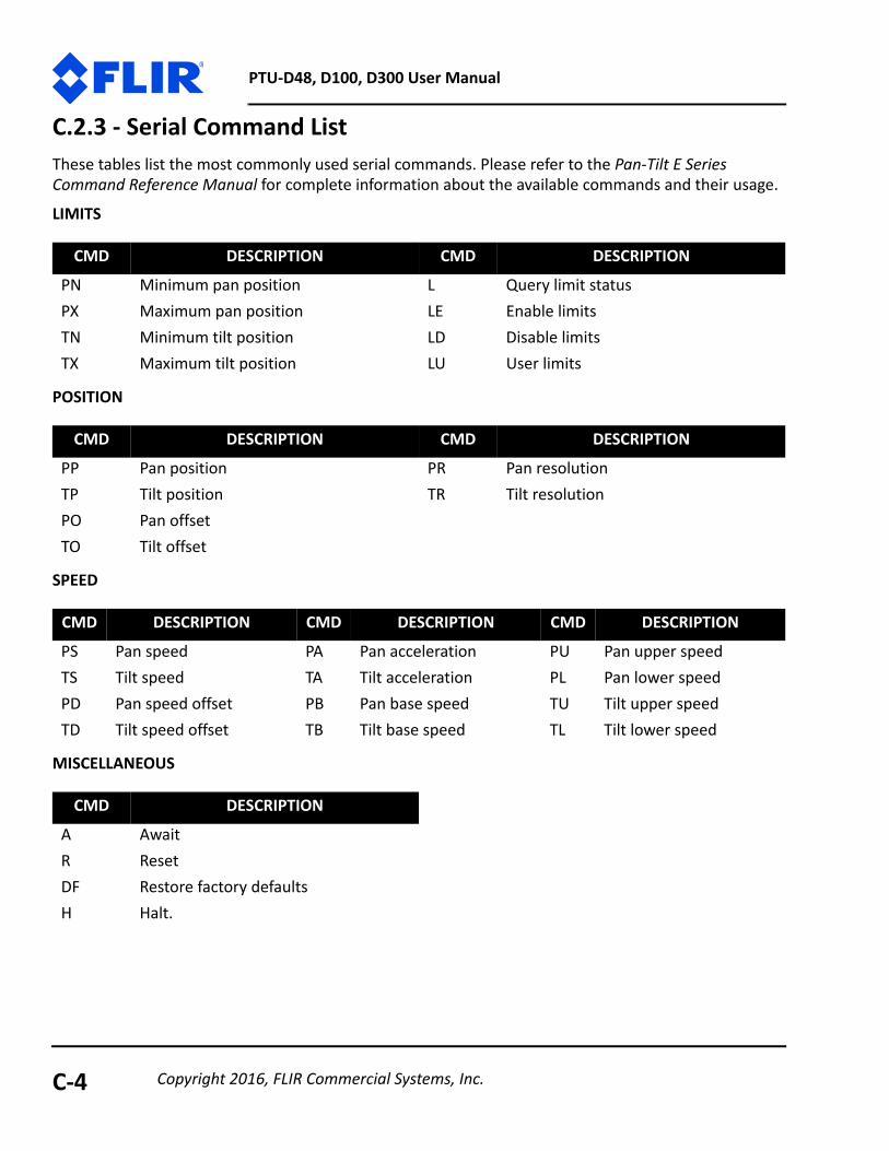
PTU-D48, D100, D300 User Manual
C.2.3 - Serial Command ListThese tables list the most commonly used serial commands. Please refer to the Pan-Tilt E Series Command Reference Manual for complete information about the available commands and their usage.
LIMITS
POSITION
SPEED
MISCELLANEOUS
CMD DESCRIPTION CMD DESCRIPTIONPN Minimum pan position L Query limit statusPX Maximum pan position LE Enable limitsTN Minimum tilt position LD Disable limitsTX Maximum tilt position LU User limits
CMD DESCRIPTION CMD DESCRIPTIONPP Pan position PR Pan resolutionTP Tilt position TR Tilt resolutionPO Pan offsetTO Tilt offset
CMD DESCRIPTION CMD DESCRIPTION CMD DESCRIPTIONPS Pan speed PA Pan acceleration PU Pan upper speedTS Tilt speed TA Tilt acceleration PL Pan lower speedPD Pan speed offset PB Pan base speed TU Tilt upper speedTD Tilt speed offset TB Tilt base speed TL Tilt lower speed
CMD DESCRIPTIONA AwaitR ResetDF Restore factory defaultsH Halt.
Copyright 2016, FLIR Commercial Systems, Inc.C-4
D - Troubleshooting
This appendix presents common mechanical, power, and networking challenges and resolutions, and also provides information about contacting FLIR Technical Support.
D.1 - MechanicalAfter powering on, the PTU stops moving with a grinding noise.• If you have a payload attached:
- The payload may be too heavy. Try moving the payload closer to the center of rotation of the affected axis and/or reducing the payload weight.
- The movement settings may be too aggressive. Reduce the upper speed limit and/or accelera-tion.
• If you do not have a payload attached, contact FLIR Technical Support.
D.2 - PowerThe PTU-D100E E Series reset movements are different than older PTU-D100E models.This is normal behavior.
D.3 - NetworkingUnable to determine the PTU IP address to access the onboard Web page.• If you are running Windows, use the PTU Finder tool included on the CD that shipped with your PTU.• If you are not running Windows, attach a serial device to the PTU host port and then issue the NI
command to query the IP address of the PTU.PTU-E46 Web page controls are sluggish.• Adjust the speeds and/or step size by clicking the Set Arrow Step Size or Set Arrow Speed headers in
the PTU Control Web page, as described in the Pan-Tilt E Series Command Reference Manual.• Try closing other programs on your computer to free up resources.
Copyright 2016, FLIR Commercial Systems, Inc. C-1

PTU-D48, D100, D300 User Manual
Unable to establish serial communications with the PTU.• If you are using RS-232:
- Make sure that the PTU is equipped with RS-232 communications at the port you are using. Units with PL01 wiring have RS-232 at the base, while units with PL02 wiring have RS-232 at the pay-load port.
- Try using a null-modem adapter.- If you are using a laptop, make sure that it is plugged in. RS-232 will not work if the PTU and host
computer grounds are too far apart.- Verify that the RS-232 port is working using a loop-back adapter. If you do not have a loop-back
adapter, connect pins 2 and 3 of the DB-9 RS-232 connector. Any characters typed into the serial terminal should be echoed back when the loop-back adapter is attached.
• If you are using the RS-232 to RS-485 adapter provided by FLIR Systems, Inc:- Set the switches to T RxON and DCE.
- Make sure the adapter is powered.- Try using a null-modem adapter.- If you are using a laptop, make sure that it is plugged in. RS-232 will not work if the PTU and host
computer grounds are too far apart.- Verify that the RS-232 port is working using a loop-back adapter. If you do not have a loop-back
adapter, connect pins 2 and 3 of the DB-9 RS-232 connector. Any characters typed into the serial terminal should be echoed back when the loop-back adapter is attached.
D.4 - Technical SupportFLIR Systems, Inc. provides a range of technical support options:• Email: [email protected]
• Web: www.FLIR.com/MCS
• Phone: (888)747-3547The preferred method of contacting Technical Support is via email, which helps ensure proper dispatching and tracking to address your questions promptly.When contacting Technical Support, please provide the following information:• PTU model and configuration
• Payload (Please include photos, if possible.)• Parameter settings
• Description of issue/symptoms
Copyright 2016, FLIR Commercial Systems, Inc.C-2
E - Regulatory & Warranty Infor-mation
E.1 - Regulatory InformationElectromagnetic Interference (EMI) is any signal or emission, either radiated in free space or conducted along power or signal leads, that endangers the function of a radio navigation or other safety service or that seriously degrades, obstructs, or repeatedly interrupts a licensed radio communications service.
Class AClass A equipment has been tested and found to comply with the limits for a Class A digital device, pur-suant to Part 15 of the FCC Rules. These limits are designed to provide reasonable protection against harmful interference in a commercial environment. This equipment generates, uses, and can radiate radio frequency energy and, if not installed and used in accordance with the instructions, may cause harmful interference to radio communications. However, there is no guarantee that interference will not occur in a particular installation. Operation of this equipment in a residential area is likely to cause harmful interference, in which case the user will be required to correct the interference at his/her own expense.
FLIR PTUs using a cable length of 7’ or less, and using the PT-PS-INT30V power supply have been tested to comply with FCC Class A requirements. Full compliance in systems using a 3’ motor cable requires an external direct connection from either the controller or the PTU head to earth ground.
Caution: Changes or modifications of this equipment not expressly approved by manufacturer could result in violation of Part 15 of the Federal Communication Commission’s rules. The FCC has prepared the following booklet: “How to Identify and Resolve Radio-TV Interference Problems.” It is available from the US Government Printing Office, Washington DC, 20402. Stock Number 004-00-00345-4.FCC NoticeAccording to 47CFR, Parts 2 and 15, Subpart B Class A:
This device complies with FCC Part 15, Subpart B Class A of the FCC Rules. Operation is subject to the fol-lowing two conditions: (1) This device may not cause harmful interference, (2) This device must accept any interference received including interference that may cause undesired operations.CE NoticeThis is a Class A product. In a domestic environment, this product may cause radio interference, in which case the user may be required to take adequate measures.
Copyright 2016, FLIR Commercial Systems, Inc. C-1
E.2 - About FLIR Systems, Inc.FLIR Systems, Inc. is the world’s largest commercial infrared company with the more high quality thermal night vision systems in the field than all other manufacturers combined. Our rugged, stabi-lized imagers are on thousands of civil and military surface and airborne platforms in the USA and around the world.
With thousands of our thermal cameras on the job in military, scientific, law enforcement, and secu-rity applications, FLIR brings an unmatched level of experience and dedication to the creation of cut-ting edge thermal night vision systems.
We design and manufacture all of the critical technologies inside our products, including detectors, electronics, special lenses, and pan/tilt motion control systems. All of our products are proudly assembled right here in the USA.
For additional technical information, or to see a demonstration of these revolutionary thermal night vision systems, contact a FLIR representative today. You can also visit www.FLIR.com to watch prod-uct videos and see how thermal imaging can help you see night and day.
In 1992, FLIR MCS (formerly Directed Perception) created one of the first miniature computer-con-trolled pan/tilt tracking mounts and continues to lead the field in innovation, applied design, and service. Our patented pant/tilt units are in use in a wide range of industries including security and surveillance, industrial automation, robotics, communications, military/aerospace, law enforce-ment, education, R&D, webcams, and teleconferencing/distance learning applications. Some of the payloads that can be precisely controlled include sensors like video cameras, thermal imagers, laser rangefinders, microwave antennas, and many more. FLIR MCS maintains engineering capabilities in mechanical design, electronics, and embedded and network software development. Find out more at www.FLIR.com/mcs.
E.3 - Limited WarrantyFLIR warrants that the Goods, at Delivery and for 365 days (Warranty Period), will conform to pub-lished specifications and be free from defects in materials, unless another Warranty Period is stated on the Front of the Acknowledgment. Buyer shall report any claimed defect in writing to FLIR promptly upon discovery and withinthe Warranty Period. FLIR shall elect either to repair or replace nonconforming Goods at the appro-priate FLIR service center nearest to Buyer (Remedy).
This warranty does not extend to: (a) Goods repaired or modified in any manner by persons other than FLIR or FLIR's authorized designee; and (b) Goods that are defective due either to normal wear and tear, or Buyer's failure to properly store, install, operate or maintain the Goods. The Remedy is FLIR's sole obligation, and Buyer's exclusive recourse, for all claims of defects with respect to the Goods.
If the Remedy is adjudicated insufficient, however, FLIR shall refund the Price paid without further liability to Buyer relating to the subject Goods. Buyer shall pay costs of returning Goods under a war-

Appendix E: Regulatory Information
ranty claim, and FLIR shall pay the costs of sending Goods to Buyer after the Remedy is performed. SELLER MAKES NO OTHER WARRANTY OF ANY KIND WITH RESPECT TO THE GOODS OR SERVICES.
ALL OTHER WARRANTIES, EXPRESS OR IMPLIED, INCLUDING BUT NOT LIMITED TO, IMPLIED WARRAN-TIES OF MERCHANTABILITY AND FITNESS FOR A PARTICULAR PURPOSE, and NONINFRINGEMENT ARE HEREBY DISCLAIMED.
Copyright 2016, FLIR Commercial Systems, Inc. C-3

PTU-D48E, D100, D300 User Manual v. 1.00 (06/2016)
70 Castilian DriveGoleta, CA 93117p: (805) 964-9797f: (805) 690-5933
www.FLIR.com/MCS