High-Performance Butterfly Valvesamwoovalve.kr/SW-HP Series.pdf · · 2009-10-23High-Performance...
12
High-Performance Butterfly Valve 100% Bi-directional tight shut off at full rated pressure. Figure Number Abbreviation SW-HRW High-performance Rubber seat Butterfly valves - WAFER type SW-HRL High-performance Rubber seat Butterfly valves - LUG type SW-HRF High-performance Rubber seat Butterfly valves - FLANGE type SW-HTW High-performance Teflon seat Butterfly valves - WAFER type SW-HTL High-performance Teflon seat Butterfly valves - LUG type SW-HTF High-performance Teflon seat Butterfly valves - FLANGE type SW-MWH High-performance Metal seat Butterfly valves - WAFER type SW-MLH High-performance Metal seat Butterfly valves - LUG type SW-MFH High-performance Metal seat Butterfly valves - FLANGE type SW-FWH High-performance Fire safe seat Butterfly valves - WAFER type SW-FLH High-performance Fire safe seat Butterfly valves - LUG type SW-FFH High-performance Fire safe seat Butterfly valves - FLANGE type Standard Compliance Conform to BS 5155, MSS SP 67 and API 609 Production Range SIZE : DN 50 to DN 2000 (2 inch ~ 80 inch) Working Pressure : upto 25 bar Working Temperature : -100 ~ +450 Connection Flange BS4504 PN10, PN16, PN25 and PN40 / DIN2501 PN10, PN16, PN25 and PN40 / ANSI B16.5 CL. 150LB and 300LB / MSS SP44 CL. 150LB and 300LB / ISO 2531 PN10, PN16, PN25 and PN40 / KS/JIS 10K, 16K & 20K / Face to Face Dimensions Conform to BS5155, ISO5752, MSS SP67 and API609 Application Crude Oil Chemical and Petro-Chemical Plants Offshore Plant Ethylene LPG Petroleum Products Sea Water Steam Textile industry Water and Others Foundry Sugar refining Food Plants Fire safer Piping system Marine tankers- Ship building
-
Upload
truongcong -
Category
Documents
-
view
214 -
download
0
Transcript of High-Performance Butterfly Valvesamwoovalve.kr/SW-HP Series.pdf · · 2009-10-23High-Performance...

High-Performance Butterfly Valve
100% Bi-directional tight shut off at full rated pressure.
Figure Number AbbreviationSW-HRW High-performance Rubber seat Butterfly valves - WAFER typeSW-HRL High-performance Rubber seat Butterfly valves - LUG typeSW-HRF High-performance Rubber seat Butterfly valves - FLANGE typeSW-HTW High-performance Teflon seat Butterfly valves - WAFER typeSW-HTL High-performance Teflon seat Butterfly valves - LUG typeSW-HTF High-performance Teflon seat Butterfly valves - FLANGE typeSW-MWH High-performance Metal seat Butterfly valves - WAFER typeSW-MLH High-performance Metal seat Butterfly valves - LUG typeSW-MFH High-performance Metal seat Butterfly valves - FLANGE typeSW-FWH High-performance Fire safe seat Butterfly valves - WAFER typeSW-FLH High-performance Fire safe seat Butterfly valves - LUG typeSW-FFH High-performance Fire safe seat Butterfly valves - FLANGE type
Standard ComplianceConform to BS 5155, MSS SP 67 and API 609
Production RangeSIZE : DN 50 to DN 2000 (2 inch ~ 80 inch)Working Pressure : upto 25 barWorking Temperature : -100 ~ +450
Connection FlangeBS4504 PN10, PN16, PN25 and PN40 / DIN2501 PN10, PN16, PN25 and PN40 /ANSI B16.5 CL. 150LB and 300LB / MSS SP44 CL. 150LB and 300LB /ISO 2531 PN10, PN16, PN25 and PN40 / KS/JIS 10K, 16K & 20K /
Face to Face DimensionsConform to BS5155, ISO5752, MSS SP67 and API609
ApplicationCrude Oil Chemical and Petro-Chemical PlantsOffshore Plant Ethylene LPGPetroleum Products Sea Water SteamTextile industry Water and Others FoundrySugar refining Food PlantsFire safer Piping system
Marine tankers- Shipbuilding

High-Performance Butterfly Valve
Design Features
Bi-directional tight shut off.
Reduced weight and overall dimensions.
Low pressure loss and reduced energy costs.
High Kv / Cv values. High reliability.
Easy to clean and disinfect for potable water
systems etc.
Easy to handle, to install, and to dismantle.
Less space in storage and installation.
Insulation of noise and heat transfer.
MATERIALPART NAMEP.NO.
1
2
3
4
5
6
7
8
9
10
11
12
13
14
15
16
17
18
19
BODY
DISC
SEAT
STEM
DISC PIN
RETAINER
RETAINER BOLT
THRUST PLATE
BOTTOM COVER
BOTTOM BOLT
BOTTOM GASKET
PACKING GLAND
GLAND RING
PACKING
TOP FLANGE
STEM BEARING
STEM BEARING
BOLT & NUT
LEVER
DUCTILE IRON, CAST STEEL,
STAINLESS STEEL, AL-BRONZE, DUPLEX
CAST STEEL, STAINLESS STEEL,
AL-BRONZE
SS. STEEL, TEFLON, RUBBER
SS. STEEL (304, 316, 316L, 630, 17-4PH, Monel)
STAINLESS STEEL
STAINLESS STEEL, DUCTILE IRON, MILD STEEL
STAINLESS STEEL
BRONZE, STAINLESS STEEL
STAINLESS STEEL, AL-BRONZE
STAINLESS STEEL
TEFLON, GRAPHITE
SS. STEEL
BRASS, STAINLESS STEEL
TEFLON, GRAPHITE, RUBBER
SS. STEEL
METALOPLAST, STAINLESS STEEL
METALOPLAST, STAINLESS STEEL
STAINLESS STEEL
STEEL, DUCTILE IRON
15High-Performance Butterfly Valve
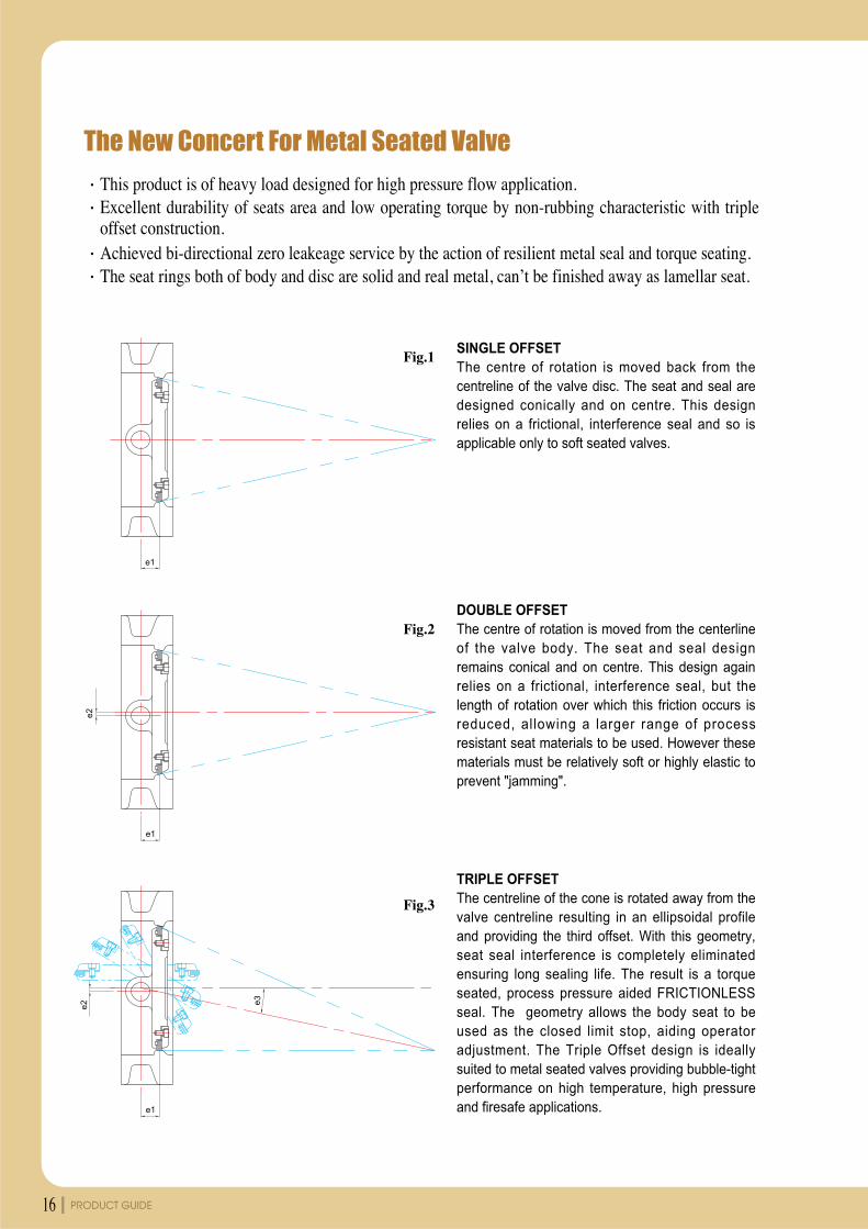
The New Concert For Metal Seated Valve
This product is of heavy load designed for high pressure flow application.Excellent durability of seats area and low operating torque by non-rubbing characteristic with tripleoffset construction.Achieved bi-directional zero leakeage service by the action of resilient metal seal and torque seating.The seat rings both of body and disc are solid and real metal, can’t be finished away as lamellar seat.
SINGLE OFFSETThe centre of rotation is moved back from thecentreline of the valve disc. The seat and seal aredesigned conically and on centre. This designrelies on a frictional, interference seal and so isapplicable only to soft seated valves.
DOUBLE OFFSETThe centre of rotation is moved from the centerlineof the valve body. The seat and seal designremains conical and on centre. This design againrelies on a frictional, interference seal, but thelength of rotation over which this friction occurs isreduced, allowing a larger range of processresistant seat materials to be used. However thesematerials must be relatively soft or highly elastic toprevent "jamming".
TRIPLE OFFSETThe centreline of the cone is rotated away from thevalve centreline resulting in an ellipsoidal profileand providing the third offset. With this geometry,seat seal interference is completely eliminatedensuring long sealing life. The result is a torqueseated, process pressure aided FRICTIONLESSseal. The geometry allows the body seat to beused as the closed limit stop, aiding operatoradjustment. The Triple Offset design is ideallysuited to metal seated valves providing bubble-tightperformance on high temperature, high pressureand firesafe applications.
PRODUCT GUIDE16
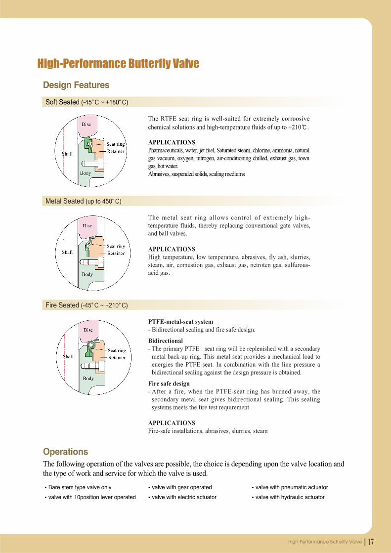
High-Performance Butterfly Valve
The RTFE seat ring is well-suited for extremely corroosivechemical solutions and high-temperature fluids of up to +210 .
APPLICATIONSPharmaceuticals, water, jet fuel, Saturated steam, chlorine, ammonia, naturalgas vacuum, oxygen, nitrogen, air-conditioning chilled, exhaust gas, towngas, hot water.Abrasives, suspended solids, scaling mediums
Soft Seated (-45 C ~ +180 C)
The metal seat ring allows control of extremely high-temperature fluids, thereby replacing conventional gate valves,and ball valves.
APPLICATIONSHigh temperature, low temperature, abrasives, fly ash, slurries,steam, air, comustion gas, exhaust gas, netroten gas, sulfurous-acid gas.
Metal Seated (up to 450 C)
PTFE-metal-seat system- Bidirectional sealing and fire safe design.
Bidirectional- The primary PTFE : seat ring will be replenished with a secondary
metal back-up ring. This metal seat provides a mechanical load toenergies the PTFE-seat. In combination with the line pressure abidirectional sealing against the design pressure is obtained.
Fire safe design- After a fire, when the PTFE-seat ring has burned away, the
secondary metal seat gives bidirectional sealing. This sealingsystems meets the fire test requirement
APPLICATIONSFire-safe installations, abrasives, slurries, steam
Fire Seated (-45 C ~ +210 C)
Operations
Design Features
The following operation of the valves are possible, the choice is depending upon the valve location andthe type of work and service for which the valve is used.
Bare stem type valve only
valve with 10position lever operated
valve with gear operated
valve with electric actuator
valve with pneumatic actuator
valve with hydraulic actuator
17High-Performance Butterfly Valve
PRODUCT GUIDE18
Triple Offset Butterfly Valve Metal to Metal Seat
Features Design Standard Specifications
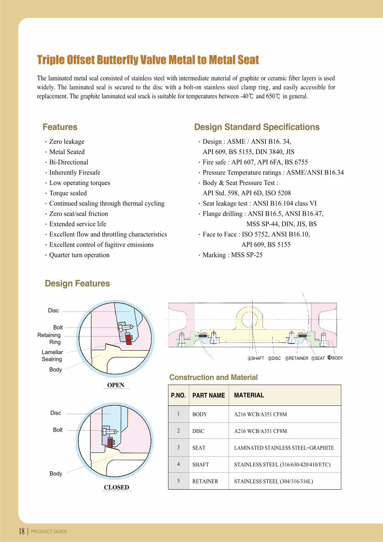
The laminated metal seal consisted of stainless steel with intermediate material of graphite or ceramic fiber layers is usedwidely. The laminated seal is secured to the disc with a bolt-on stainless steel clamp ring, and easily accessible forreplacement. The graphite laminated seal srack is suitable for temperatures between -40 and 650 in general.
Design Features
Construction and Material
Zero leakage
Metal Seated
Bi-Directional
Inherently Firesafe
Low operating torques
Torque sealed
Continued sealing through thermal cycling
Zero seat/seal friction
Extended service life
Excellent flow and throttling characteristics
Excellent control of fugitive emissions
Quarter turn operation
Design : ASME / ANSI B16. 34,
API 609, BS 5155, DIN 3840, JIS
Fire safe : API 607, API 6FA, BS 6755
Pressure Temperature ratings : ASME/ANSI B16.34
Body & Seat Pressure Test :
API Std. 598, API 6D, ISO 5208
Seat leakage test : ANSI B16.104 class VI
Flange drilling : ANSI B16.5, ANSI B16.47,
MSS SP-44, DIN, JIS, BS
Face to Face : ISO 5752, ANSI B16.10,
API 609, BS 5155
Marking : MSS SP-25
RetainingRing
LamellarSealring
Bolt
Disc
Body
OPEN
Bolt
Disc
Body
CLOSED
SHAFT DISC RETAINER SEAT BODY
MATERIALPART NAMEP.NO.
1
2
3
4
5
BODY
DISC
SEAT
SHAFT
RETAINER
A216 WCB/A351 CF8M
A216 WCB/A351 CF8M
LAMINATED STAINLESS STEEL+GRAPHITE
STAINLESS STEEL (316/630/420/410/ETC)
STAINLESS STEEL (304/316/316L)
19High-Performance Butterfly Valve
unit : mm
˛2"
2.5"
3"
4"
5"
6"
8"
10"
12"
14"
16"
18"
20"
22"
24"
26"
28"
30"
32"
36"
40"
44"
48"
56"
64"
72"
80"
50
65
80
100
125
150
200
250
300
350
400
450
500
550
600
650
700
750
800
900
1000
1100
1200
1400
1600
1800
2000
50
65
80
100
125
150
200
250
300
350
400
450
500
550
600
650
700
750
800
900
1000
1100
1200
1400
1600
1800
2000
43
46
48
54
57
57
64
71
81
92
102
114
127
154
154
165
165
190
190
203
216
254
254
280
360
360
400
60
70
75
100
110
130
150
245
285
342
380
402
432
465
510
540
570
595
640
705
675
830
890
950
1100
1200
1275
180
180
185
200
215
235
255
300
320
440
460
492
552
572
610
630
665
695
740
800
865
925
990
1160
1260
1370
1450
35
35
35
35
35
35
50
50
50
80
80
120
120
120
120
120
120
140
140
140
140
170
170
180
180
200
220
16
16
19
19
20
20
25
32
32
42
42
50
50
65
65
65
65
80
80
90
90
120
120
140
140
170
170
F 07
F 07
F 07
F 07
F 07
F 07
F 10
F 10
F 10
F 14
F 14
F 16
F 16
F 16
F 16
F 16
F 25
F 25
F 25
F 25
F 25
F 30
F 30
F 30
F 35
F 35
F 40
120
140
150
175
210
240
290
355
400
445
510
565
620
680
730
780
840
900
950
1050
1160
1270
1380
-
-
-
-
4
4
8
8
8
8
12
12
16
16
16
20
20
20
24
24
24
24
28
28
28
28
32
-
-
-
-
19
19
19
19
23
23
23
25
M22
M22
M24
M24
M24
M30
M30
M30
M30
M30
M30
M30
M36
M36
M36
-
-
-
-
120.5
139.5
152.5
190.5
216.0
241.5
298.5
362.0
432.0
476.0
539.5
578.0
635.0
392.2
749.5
806.5
863.5
914.5
978.0
1086.0
1200.0
1314.5
1422.4
1651
-
2095.5
2230
4
4
4
8
8
8
8
12
12
12
16
16
20
20
20
24
28
28
28
32
36
40
44
48
-
60
48
19
19
19
19
22
22
22
25
25
29
1"
1
1
1
1
1
1
1
1
1
1
1
1
1
-
1
1
125
145
160
180
210
240
295
350
400
460
515
565
620
-
725
-
840
-
950
1050
1160
-
1380
1590
1820
2020
2230
4
4
8
8
8
8
8
12
12
16
16
20
20
-
20
-
24
-
24
28
28
-
32
36
40
44
48
19
19
19
19
19
23
23
23
23
M20
M24
M24
M24
-
M27
-
M27
-
M30
M30
M33
-
M36
M39
M45
M45
M45
4.5
5.5
9.0
10.0
13.0
17.0
26.0
40.0
68.0
93.0
121.0
144.0
160.0
228.0
284.0
327.0
388.0
462.0
607.0
860.0
1180.0
1460.0
1800.0
2045.0
2570.0
2895.0
3120.0
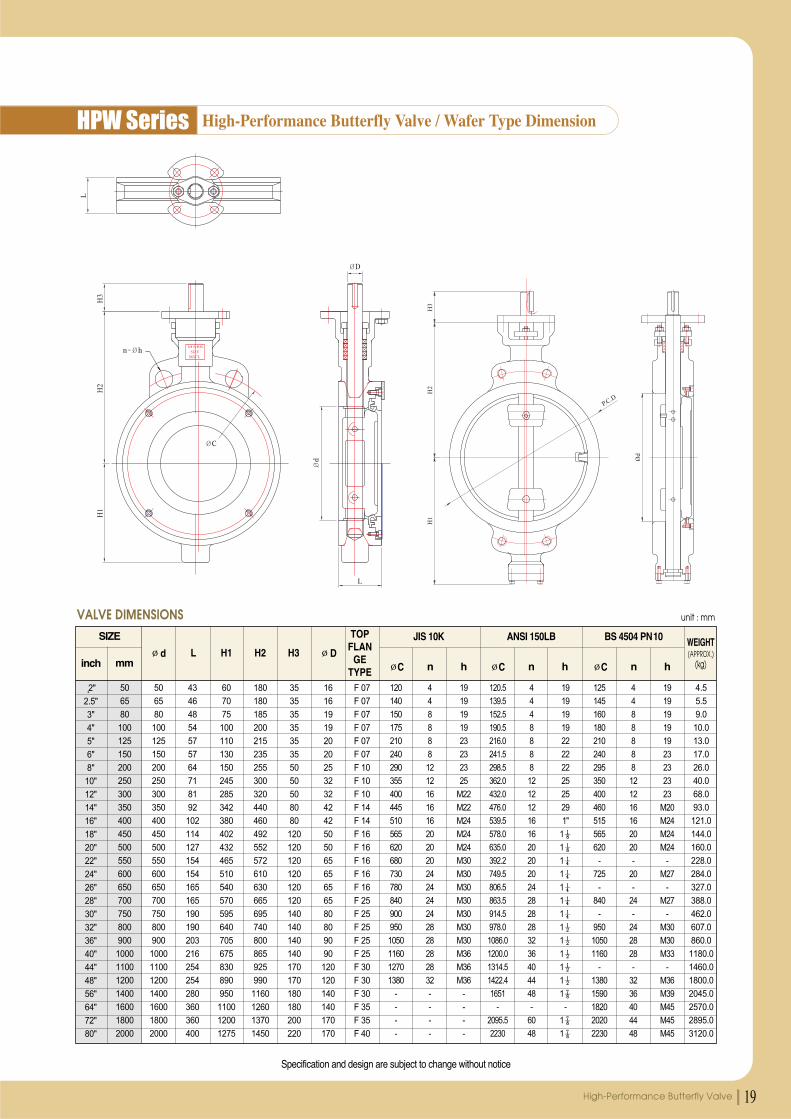
mminch
SIZE
d L H1 H2 H3 D
TOPFLAN
GETYPE
WEIGHT(APPROX.)
(kg)
VALVE DIMENSIONS
hnC
JIS 10K
hnC
ANSI 150LB
hnC
BS 4504 PN10
Specification and design are subject to change without notice
HPW Series High-Performance Butterfly Valve / Wafer Type Dimension
PRODUCT GUIDE20
unit : mm
˛2"
2.5"
3"
4"
5"
6"
8"
10"
12"
14"
16"
18"
20"
22"
24"
26"
28"
30"
32"
36"
40"
44"
48"
56"
64"
72"
80"
50
65
80
100
125
150
200
250
300
350
400
450
500
550
600
650
700
750
800
900
1000
1100
1200
1400
1600
1800
2000
50
65
80
100
125
150
200
250
300
350
400
450
500
550
600
650
700
750
800
900
1000
1100
1200
1400
1600
1800
2000
43
46
48
54
57
57
64
71
81
92
102
114
127
154
154
165
165
190
190
203
216
254
254
280
360
360
400
115
130
140
160
185
190
220
270
300
342
380
402
432
465
510
540
570
595
640
705
675
830
890
950
1100
1200
1275
182
200
215
232
245
260
292
353
372
440
460
492
552
572
610
630
665
695
740
800
865
925
990
1160
1260
1370
1450
45
45
45
45
45
45
65
65
65
80
80
120
120
120
120
120
120
140
140
140
140
170
170
180
180
200
220
16
16
19
19
20
20
25
32
32
42
42
50
50
65
65
65
65
80
80
90
90
120
120
140
140
170
170
F 07
F 07
F 07
F 07
F 07
F 07
F 10
F 10
F 10
F 14
F 14
F 16
F 16
F 16
F 16
F 16
F 25
F 25
F 25
F 25
F 25
F 30
F 30
F 30
F 35
F 35
F 40
120
140
150
175
210
240
290
355
400
445
510
565
620
680
730
780
840
900
950
1050
1160
1270
1380
-
-
-
-
4
4
8
8
8
8
12
12
16
16
16
20
20
20
24
24
24
24
28
28
28
28
32
-
-
-
-
19
19
19
19
23
23
23
25
M22
M22
M24
M24
M24
M30
M30
M30
M30
M30
M30
M30
M36
M36
M36
-
-
-
-
120.5
139.5
152.5
190.5
216.0
241.5
298.5
362.0
432.0
476.0
539.5
578.0
635.0
392.2
749.5
806.5
863.5
914.5
978.0
1086.0
1200.0
1314.5
1422.4
1651
-
2095.5
2230
4
4
4
8
8
8
8
12
12
12
16
16
20
20
20
24
28
28
28
32
36
40
44
48
-
60
48
19
19
19
19
22
22
22
25
25
29
1"
1
1
1
1
1
1
1
1
1
1
1
1
1
-
1
1
125
145
160
180
210
240
295
350
400
460
515
565
620
-
725
-
840
-
950
1050
1160
-
1380
1590
1820
2020
2230
4
4
8
8
8
8
8
12
12
16
16
20
20
-
20
-
24
-
24
28
28
-
32
36
40
44
48
M16
M16
M16
M16
M16
M20
M20
M20
M20
M20
M24
M24
M24
-
M27
-
M27
-
M30
M30
M33
-
M36
M39
M45
M45
M45
4.5
5.5
9.0
10.0
13.0
17.0
26.0
40.0
68.0
93.0
121.0
144.0
160.0
228.0
284.0
327.0
388.0
462.0
607.0
860.0
1180.0
1460.0
1800.0
2045.0
2570.0
2895.0
3120.0
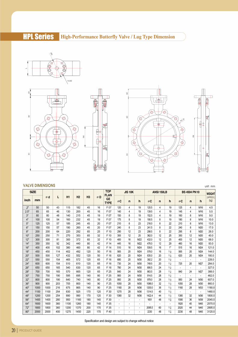
mminch
SIZE
d L H1 H2 H3 D
TOPFLAN
GETYPE
WEIGHT(APPROX.)
(kg)
VALVE DIMENSIONS
hnC
JIS 10K
hnC
ANSI 150LB
hnC
BS 4504 PN10
Specification and design are subject to change without notice
HPL Series High-Performance Butterfly Valve / Lug Type Dimension
21High-Performance Butterfly Valve
unit : mm
˛2"
2.5"
3"
4"
5"
6"
8"
10"
12"
14"
16"
18"
20"
22"
24"
26"
28"
30"
32"
36"
40"
44"
48"
56"
64"
72"
80"
50
65
80
100
125
150
200
250
300
350
400
450
500
550
600
650
700
750
800
900
1000
1100
1200
1400
1600
1800
2000
50
65
80
100
125
150
200
250
300
350
400
450
500
550
600
650
700
750
800
900
1000
1100
1200
1400
1600
1800
2000
43
46
48
54
57
57
64
71
81
92
102
114
127
154
154
165
165
190
190
203
216
254
254
280
360
360
400
115
130
140
160
185
190
220
270
300
342
380
402
432
465
510
540
570
595
640
705
675
830
890
950
1100
1200
1275
182
200
215
232
245
260
292
353
372
440
460
492
552
572
610
630
665
695
740
800
865
925
990
1160
1260
1370
1450
45
45
45
45
45
45
65
65
65
80
80
120
120
120
120
120
120
140
140
140
140
170
170
180
180
200
220
16
16
19
19
20
20
25
32
32
42
42
50
50
65
65
65
65
80
80
90
90
120
120
140
140
170
170
F 07
F 07
F 07
F 07
F 07
F 07
F 10
F 10
F 10
F 14
F 14
F 16
F 16
F 16
F 16
F 16
F 25
F 25
F 25
F 25
F 25
F 30
F 30
F 30
F 35
F 35
F 40
120
140
150
175
210
240
290
355
400
445
510
565
620
680
730
780
840
900
950
1050
1160
1270
1380
-
-
-
-
4
4
8
8
8
8
12
12
16
16
16
20
20
20
24
24
24
24
28
28
28
28
32
-
-
-
-
19
19
19
19
23
23
23
25
M22
M22
M24
M24
M24
M30
M30
M30
M30
M30
M30
M30
M36
M36
M36
-
-
-
-
120.5
139.5
152.5
190.5
216.0
241.5
298.5
362.0
432.0
476.0
539.5
578.0
635.0
392.2
749.5
806.5
863.5
914.5
978.0
1086.0
1200.0
1314.45
1422.4
1651
-
2095.5
2230
4
4
4
8
8
8
8
12
12
12
16
16
20
20
20
24
28
28
28
32
36
40
44
48
-
60
48
19
19
19
19
22
22
22
25
25
29
1"
1
1
1
1
1
1
1
1
1
1
1
1
1
-
1
1
125
145
160
180
210
240
295
350
400
460
515
565
620
-
725
-
840
-
950
1050
1160
-
1380
1590
1820
2020
2230
4
4
8
8
8
8
8
12
12
16
16
20
20
-
20
-
24
-
24
28
28
-
32
36
40
44
48
19
19
19
19
19
23
23
23
23
M20
M24
M24
M24
-
M27
-
M27
-
M30
M30
M33
-
M36
M39
M45
M45
M45
4.5
5.5
9.0
10.0
13.0
17.0
26.0
40.0
68.0
93.0
121.0
144.0
160.0
228.0
284.0
327.0
388.0
462.0
607.0
860.0
1180.0
1460.0
1800.0
2045.0
2570.0
2895.0
3120.0
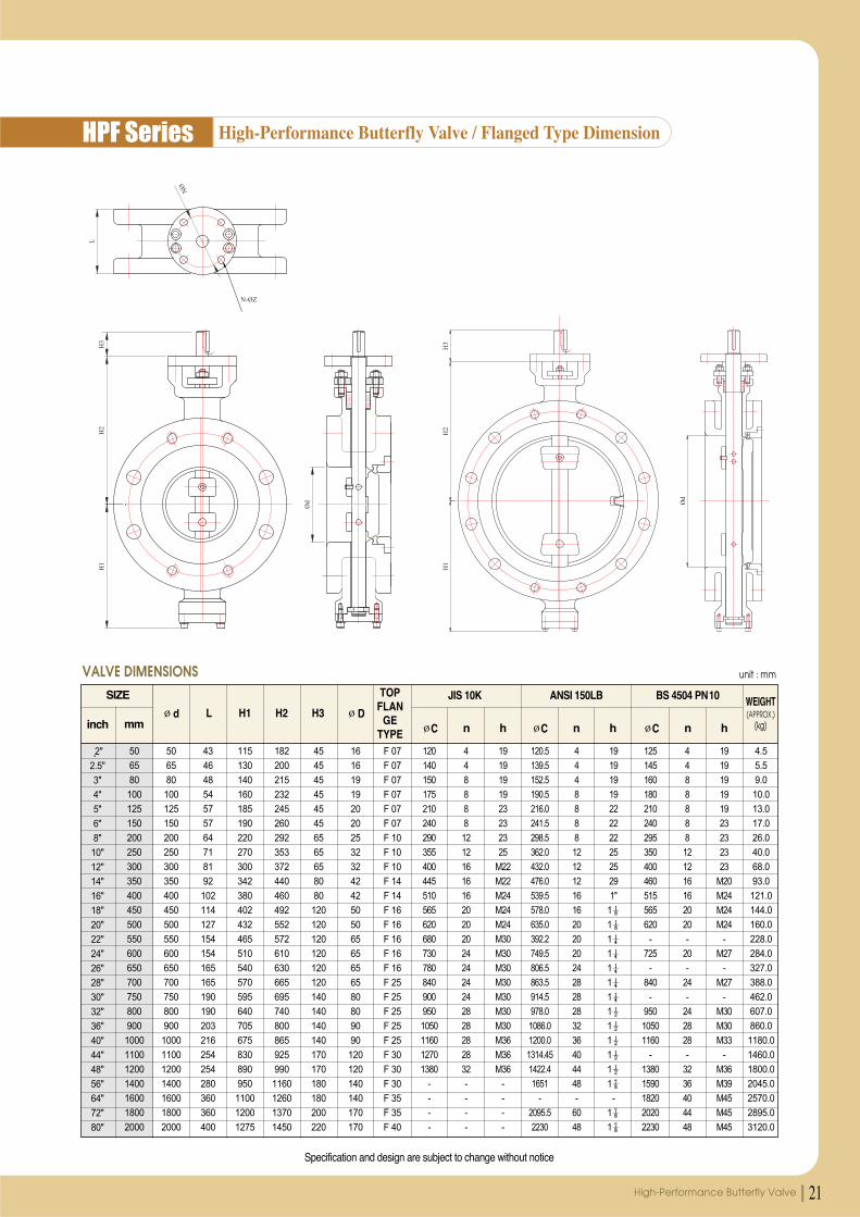
mminch
SIZE
d L H1 H2 H3 D
TOPFLAN
GETYPE
WEIGHT(APPROX.)
(kg)
VALVE DIMENSIONS
hnC
JIS 10K
hnC
ANSI 150LB
hnC
BS 4504 PN10
Specification and design are subject to change without notice
HPF Series High-Performance Butterfly Valve / Flanged Type Dimension

PRODUCT GUIDE22
Torques Required to Operate High-Performance Butterfly Valves
50
65
80
100
125
150
200
250
300
350
400
450
500
600
700
800
2
2.5
3
4
5
6
8
10
12
14
16
18
20
24
28
32
0.95
1.40
2.05
3.70
6.50
11.00
24.50
32.00
43.50
62.00
83.00
99.50
129.00
223.00
335.00
480.80
9.31
13.72
20.09
36.26
63.70
107.80
240.10
313.60
426.30
607.60
813.40
975.10
1264.20
2185.40
3283.00
4711.84
6.87
10.13
14.83
26.76
47.01
79.56
177.21
231.46
314.63
448.45
600.34
716.07
933.06
1612.96
2423.05
3477.62
1.16
1.89
2.86
4.87
7.98
15.54
28.56
44.52
60.48
86.52
115.92
150.36
210.00
328.44
483.84
677.04
11.32
18.52
27.99
47.75
78.20
152.29
279.89
436.30
592.70
847.90
1136.06
1473.53
2058.00
3218.71
4741.63
6634.99
8.39
13.67
20.69
35.22
57.72
112.40
206.57
322.01
437.45
625.80
838.45
1087.55
1518.93
2375.60
3499.61
4897.02
1.80
2.31
4.03
6.38
10.50
21.00
35.28
54.60
91.56
128.52
173.04
230.16
299.88
496.44
733.32
1030.68
17.65
22.65
39.52
62.57
102.97
205.94
345.98
535.44
897.89
1260.35
1696.94
2257.09
2940.81
4868.40
7191.39
10107.48
127.68
163.85
285.85
452.54
744.78
1489.55
2502.45
3872.84
6494.45
9116.07
12273.92
16325.50
21270.82
35213.04
52015.20
73107.28
-m -m -mNm Nm Nmft-lb ft-lb ft-lb
Working Pressure
5 bar 10 barmm inch
TORQUE TABLE unit : kg-m/Nm/ft-lb
16 bar
The oerating speed of the actuator must be considered in order to avoid waterhammer when the valve is closed in junction with Liquid.
The factors affect the torque required to operate Butterfly valves.
Actuator torques can be calculated using the follwing formulas.
Valve DiameterShaft DiameterBearing Friction CoefficientType of Seat MaterialShut off Pressure
VelocityShape of DiscSystem Head CharacteristicsPiping Arrangement
Ta = Tb + Ts + Th = 1.2Tb TdTs = CsD2
Tb = 4.17D2dfPTd = CtD3PTh = 3.06D4
Ta : The required actuator torque(lb-ft)Ts : Seating or unseating torque(lb-ft)Td : Dynamic torque(lb-ft)Th : Hydrostatic torque(lb-ft)Q : Flow(cubic for per second)V : Velocity(feet per second)D : Diameter of valve(feet)d : Diameter of Shaft(inch)P : Pressure drop across valve(psi)Cs : Coefficient of Seating or unseating torqueCt : Coefficient of dynamic torqueCf : Coefficient of flowf : Bearing friction coefficient
V = Cf p = 0.785D2
Q
23High-Performance Butterfly Valve
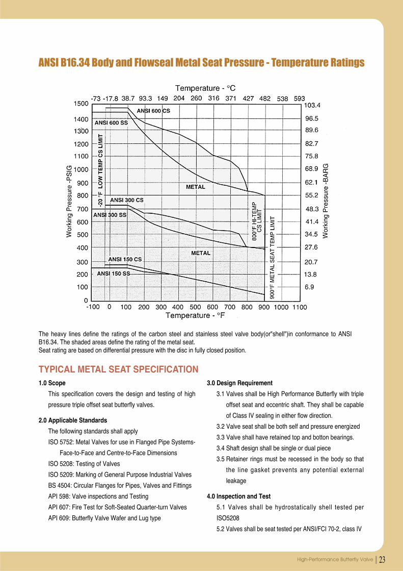
ANSI B16.34 Body and Flowseal Metal Seat Pressure - Temperature Ratings
The heavy lines define the ratings of the carbon steel and stainless steel valve body(or"shell")in conformance to ANSIB16.34. The shaded areas define the rating of the metal seat.Seat rating are based on differential pressure with the disc in fully closed position.
TYPICAL METAL SEAT SPECIFICATION1.0 Scope
This specification covers the design and testing of high
pressure triple offset seat butterfly valves.
2.0 Applicable Standards
The following standards shall apply
ISO 5752: Metal Valves for use in Flanged Pipe Systems-
Face-to-Face and Centre-to-Face Dimensions
ISO 5208: Testing of Valves
ISO 5209: Marking of General Purpose Industrial Valves
BS 4504: Circular Flanges for Pipes, Valves and Fittings
API 598: Valve inspections and Testing
API 607: Fire Test for Soft-Seated Quarter-turn Valves
API 609: Butterfly Valve Wafer and Lug type
3.0 Design Requirement
3.1 Valves shall be High Performance Butterfly with triple
offset seat and eccentric shaft. They shall be capable
of Class IV sealing in either flow direction.
3.2 Valve seat shall be both self and pressure energized
3.3 Valve shall have retained top and botton bearings.
3.4 Shaft design shall be single or dual piece
3.5 Retainer rings must be recessed in the body so that
the line gasket prevents any potential external
leakage
4.0 Inspection and Test
5.1 Valves shall be hydrostatically shell tested per
ISO5208
5.2 Valves shall be seat tested per ANSI/FCI 70-2, class IV
PRODUCT GUIDE24
Engineering Data
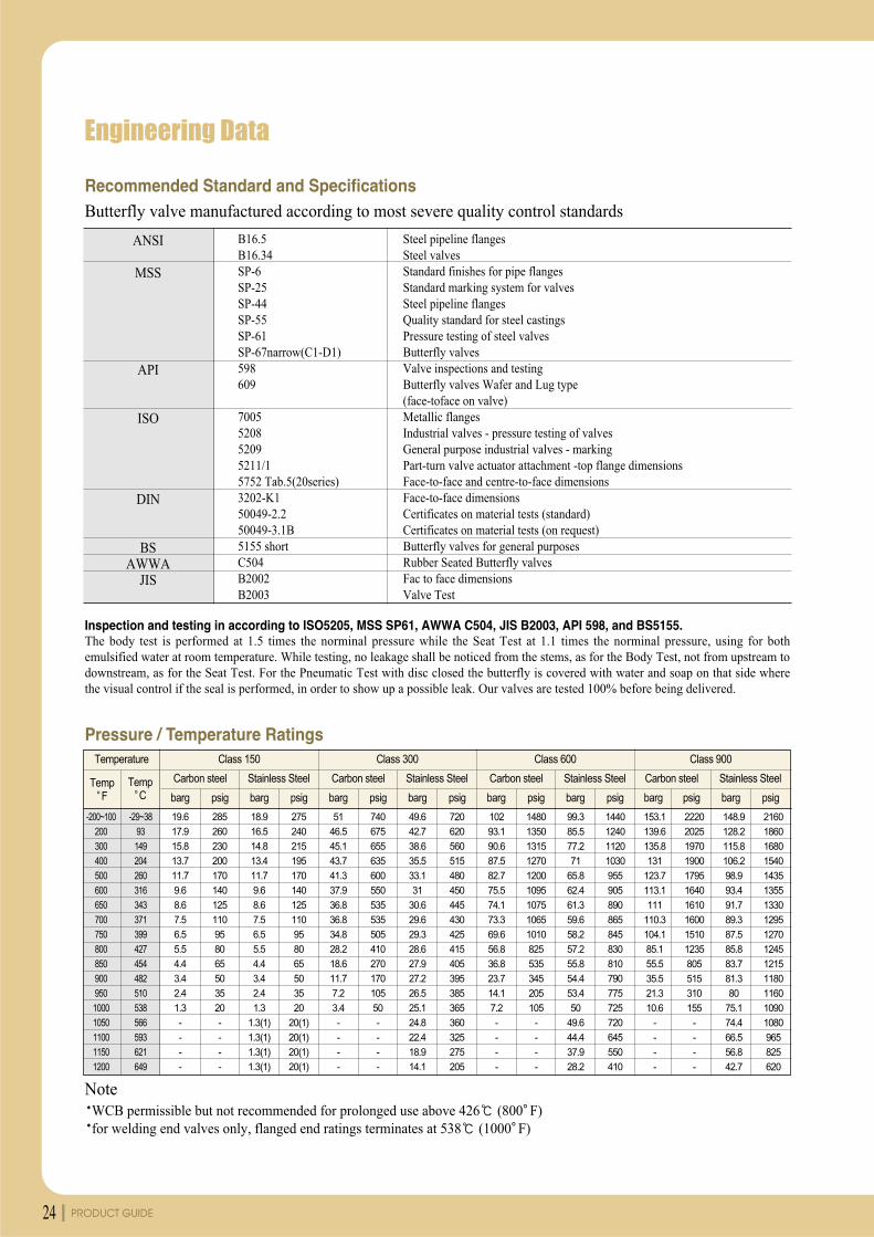
Pressure / Temperature Ratings
Recommended Standard and Specifications
NoteWCB permissible but not recommended for prolonged use above 426 (800 F)for welding end valves only, flanged end ratings terminates at 538 (1000 F)
Butterfly valve manufactured according to most severe quality control standards
Inspection and testing in according to ISO5205, MSS SP61, AWWA C504, JIS B2003, API 598, and BS5155.The body test is performed at 1.5 times the norminal pressure while the Seat Test at 1.1 times the norminal pressure, using for bothemulsified water at room temperature. While testing, no leakage shall be noticed from the stems, as for the Body Test, not from upstream todownstream, as for the Seat Test. For the Pneumatic Test with disc closed the butterfly is covered with water and soap on that side wherethe visual control if the seal is performed, in order to show up a possible leak. Our valves are tested 100% before being delivered.
-200~100
200
300
400
500
600
650
700
750
800
850
900
950
1000
1050
1100
1150
1200
-29~38
93
149
204
260
316
343
371
399
427
454
482
510
538
566
593
621
649
19.6
17.9
15.8
13.7
11.7
9.6
8.6
7.5
6.5
5.5
4.4
3.4
2.4
1.3
-
-
-
-
285
260
230
200
170
140
125
110
95
80
65
50
35
20
-
-
-
-
18.9
16.5
14.8
13.4
11.7
9.6
8.6
7.5
6.5
5.5
4.4
3.4
2.4
1.3
1.3(1)
1.3(1)
1.3(1)
1.3(1)
275
240
215
195
170
140
125
110
95
80
65
50
35
20
20(1)
20(1)
20(1)
20(1)
51
46.5
45.1
43.7
41.3
37.9
36.8
36.8
34.8
28.2
18.6
11.7
7.2
3.4
-
-
-
-
740
675
655
635
600
550
535
535
505
410
270
170
105
50
-
-
-
-
49.6
42.7
38.6
35.5
33.1
31
30.6
29.6
29.3
28.6
27.9
27.2
26.5
25.1
24.8
22.4
18.9
14.1
720
620
560
515
480
450
445
430
425
415
405
395
385
365
360
325
275
205
102
93.1
90.6
87.5
82.7
75.5
74.1
73.3
69.6
56.8
36.8
23.7
14.1
7.2
-
-
-
-
1480
1350
1315
1270
1200
1095
1075
1065
1010
825
535
345
205
105
-
-
-
-
99.3
85.5
77.2
71
65.8
62.4
61.3
59.6
58.2
57.2
55.8
54.4
53.4
50
49.6
44.4
37.9
28.2
1440
1240
1120
1030
955
905
890
865
845
830
810
790
775
725
720
645
550
410
153.1
139.6
135.8
131
123.7
113.1
111
110.3
104.1
85.1
55.5
35.5
21.3
10.6
-
-
-
-
2220
2025
1970
1900
1795
1640
1610
1600
1510
1235
805
515
310
155
-
-
-
-
148.9
128.2
115.8
106.2
98.9
93.4
91.7
89.3
87.5
85.8
83.7
81.3
80
75.1
74.4
66.5
56.8
42.7
2160
1860
1680
1540
1435
1355
1330
1295
1270
1245
1215
1180
1160
1090
1080
965
825
620
TempF
TempC
Temperature Class 150
Carbon steel
barg psig barg psig
Stainless Steel
Class 300
Carbon steel
barg psig barg psig
Stainless Steel
Class 600
Carbon steel
barg psig barg psig
Stainless Steel
Class 900
Carbon steel
barg psig barg psig
Stainless Steel
B16.5B16.34SP-6SP-25SP-44SP-55SP-61SP-67narrow(C1-D1)598609
7005520852095211/15752 Tab.5(20series)3202-K150049-2.250049-3.1B5155 shortC504B2002B2003
Steel pipeline flangesSteel valvesStandard finishes for pipe flangesStandard marking system for valvesSteel pipeline flangesQuality standard for steel castingsPressure testing of steel valvesButterfly valvesValve inspections and testingButterfly valves Wafer and Lug type(face-toface on valve)Metallic flangesIndustrial valves - pressure testing of valvesGeneral purpose industrial valves - markingPart-turn valve actuator attachment -top flange dimensionsFace-to-face and centre-to-face dimensionsFace-to-face dimensionsCertificates on material tests (standard)Certificates on material tests (on request)Butterfly valves for general purposesRubber Seated Butterfly valvesFac to face dimensionsValve Test
ANSI
MSS
API
ISO
DIN
BSAWWA
JIS
25High-Performance Butterfly Valve
Installation Instructions
GeneralValve can be installed in the pipeline in any position.Before installing valves, the pipeline must be cleaned from dirt and welding residues.Otherwise seat may be damaged.The pipeline must be free from tention and electric current.When handling valves, be careful to avoid contact with or impact by other equipment, vault walls or trench walls.Check carefully to see if valve seat/disc surface, as well as mating face, is all clean.Tighten again, if any, all bolts loosened during transport and/or handling.Open and close valves to check for proper operation.If possible, install valves in the direction of arrow mark on it for easier access and maintenance.Do not use valve as a substitute for jack when putting pipes in alignment.The span of pipeline having connection between valve and pipe should be free from such excessive loading as maycause serious bending.
Installation on the existing pipeline.Verify the distance between two flanges to be equal to face to face valve dimension.In order to facillitate installation of the valve, allow a sufficent room with adequate tools in between two flanges.Insert at least two flange-bolts through the two bottom pipe flange holes to rest valves on during installation.Close valve disc partially so that disc edge is at least 10 mm within the body.Insert valve in between two flanges. Flange gaskets should be positioned, aligned with valve bore.Valve will be held by the two flange-bolts previously fitted in the lower part of flanges.Insert the remaining flange-bolts aligning the valve with the flanges and tightening flange-bolts manually.Maintain the valve alighed, remove gradually flage spreaders and tighten bolts partially.Control open and close operation of valve to be easy and smooth.Open the valve completely and cross tighten the bolts to adequate torque.
Installation of lug type butterfly valves has the same procedure with wafer type exceptusing cap screws instead of bolts and nuts.
Installation of the new pipelineShut partially valve disc until disc profile is at least 10 mm within the body.Align the two flanges with the valves body. Flange gaskets should be positioned, aligned with valve bore.Span the body with some flange-bolts and tighten the bolts partially.Finish tightening by uniform cross bolting. Use the flange-valve-flange unit for pipe centering.Tack-weld the flanges to the pipe.Remove the bolts and the valve from the flanges. Just perform tack-welding onywhen the valve is inserted, high heat temperature can damage valve seat.Weld flages to the pipe and wait until completely cooled down.Install the valve by applying the same instruction procedure as the installation instruction on the existing pipeline.
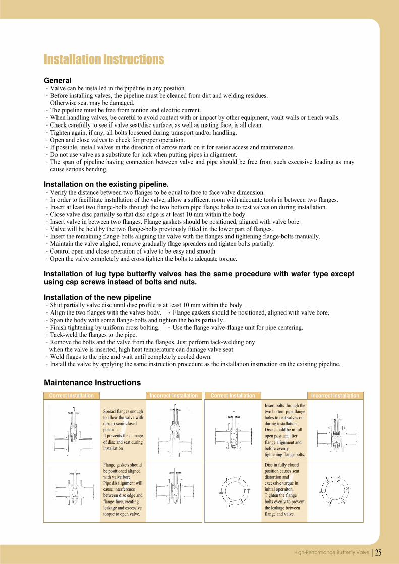
Maintenance Instructions
1
2Flange gaskets shouldbe positioned alignedwith valve bore.Pipe disalignment willcause interferencebetween disc edge andflange face, creatingleakage and excessivetorque to open valve.
Spread flanges enoughto allow the valve withdisc in semi-closedposition.It prevents the damageof disc and seat duringinstallation
Correct Installation Incorrect Installation
3
4Disc in fully closedposition causes seatdistortion andexcessive torque ininitial operaiton.Tighten the flangebolts evenly to preventthe leakage betweenflange and valve.
Insert bolts through thetwo bottom pipe flangeholes to rest valves onduring installation.Disc should be in fullopen position afterflange alignment andbefore evenlytightening flange bolts.
Correct Installation Incorrect Installation