High-Level Synthesis of Digital Microfluidic...
32
16 High-Level Synthesis of Digital Microfluidic Biochips FEI SU Intel Corporation and KRISHNENDU CHAKRABARTY Duke University Microfluidic biochips offer a promising platform for massively parallel DNA analysis, automated drug discovery, and real-time biomolecular recognition. Current techniques for full-custom design of droplet-based “digital” biochips do not scale well for concurrent assays and for next-generation system-on-chip (SOC) designs that are expected to include microfluidic components. We propose a system design methodology that attempts to apply classical high-level synthesis techniques to the design of digital microfluidic biochips. We focus here on the problem of scheduling bioassay functions under resource constraints. We first develop an optimal scheduling strategy based on integer linear programming. However, because the scheduling problem is NP-complete, we also develop two heuristic techniques that scale well for large problem instances. A clinical diagnostic procedure, namely multiplexed in-vitro diagnostics on human physiological fluids, is first used to illustrate and evaluate the proposed method. Next, the synthesis approach is applied to a protein assay, which serves as a more complex bioassay application. The proposed synthesis approach is expected to reduce human effort and design cycle time, and it will facilitate the integration of microfluidic components with microelectronic components in next-generation SOCs. Categories and Subject Descriptors: B.7.2 [Integrated Circuits]: Design Aids; B.8.2 [Perfor- mance and Reliability]: Performance Analysis and Design Aids; J.3 [Life and Medical Sci- ences]: Biology and genetics, Health General Terms: Algorithms, Performance, Design, Reliability Additional Key Words and Phrases: High-level synthesis, scheduling, microfluidics, biochips, system-on-chip This research was supported in part by the National Science Foundation under grants IIS-0312352 and CCF-0541055. A preliminary and abridged version of this article was presented in Proceedings of the IEEE International Conference on Computer-Aided Design. 2004, 223–228. Authors’ addresses: F. Su, Intel Corporation FM7-287, 1900 Prairie City Road, Folsom, CA 95630; email: [email protected]; K. Chakrabarty, Department of Electrical and Computer Engineering, Duke University, Durham, NC 27708; email: [email protected]. Permission to make digital or hard copies of part or all of this work for personal or classroom use is granted without fee provided that copies are not made or distributed for profit or direct commercial advantage and that copies show this notice on the first page or initial screen of a display along with the full citation. Copyrights for components of this work owned by others than ACM must be honored. Abstracting with credit is permitted. To copy otherwise, to republish, to post on servers, to redistribute to lists, or to use any component of this work in other works requires prior specific permission and/or a fee. Permissions may be requested from Publications Dept., ACM, Inc., 2 Penn Plaza, Suite 701, New York, NY 10121-0701 USA, fax +1 (212) 869-0481, or [email protected]. C ⃝ 2008 ACM 1550-4832/2008/01-ART16 $5.00. DOI 10.1145/1324177.1324178 http://doi.acm.org/ 10.1145/1324177.1324178 ACM Journal on Emerging Technologies in Computing Systems, Vol. 3, No. 4, Article 16, Pub. date: January 2008.
Transcript of High-Level Synthesis of Digital Microfluidic...

16
High-Level Synthesis of DigitalMicrofluidic Biochips
FEI SUIntel CorporationandKRISHNENDU CHAKRABARTYDuke University
Microfluidic biochips offer a promising platform for massively parallel DNA analysis, automateddrug discovery, and real-time biomolecular recognition. Current techniques for full-custom designof droplet-based “digital” biochips do not scale well for concurrent assays and for next-generationsystem-on-chip (SOC) designs that are expected to include microfluidic components. We proposea system design methodology that attempts to apply classical high-level synthesis techniques tothe design of digital microfluidic biochips. We focus here on the problem of scheduling bioassayfunctions under resource constraints. We first develop an optimal scheduling strategy based oninteger linear programming. However, because the scheduling problem is NP-complete, we alsodevelop two heuristic techniques that scale well for large problem instances. A clinical diagnosticprocedure, namely multiplexed in-vitro diagnostics on human physiological fluids, is first used toillustrate and evaluate the proposed method. Next, the synthesis approach is applied to a proteinassay, which serves as a more complex bioassay application. The proposed synthesis approach isexpected to reduce human effort and design cycle time, and it will facilitate the integration ofmicrofluidic components with microelectronic components in next-generation SOCs.
Categories and Subject Descriptors: B.7.2 [Integrated Circuits]: Design Aids; B.8.2 [Perfor-mance and Reliability]: Performance Analysis and Design Aids; J.3 [Life and Medical Sci-ences]: Biology and genetics, Health
General Terms: Algorithms, Performance, Design, Reliability
Additional Key Words and Phrases: High-level synthesis, scheduling, microfluidics, biochips,system-on-chip
This research was supported in part by the National Science Foundation under grants IIS-0312352and CCF-0541055.A preliminary and abridged version of this article was presented in Proceedings of the IEEEInternational Conference on Computer-Aided Design. 2004, 223–228.Authors’ addresses: F. Su, Intel Corporation FM7-287, 1900 Prairie City Road, Folsom, CA 95630;email: [email protected]; K. Chakrabarty, Department of Electrical and Computer Engineering,Duke University, Durham, NC 27708; email: [email protected] to make digital or hard copies of part or all of this work for personal or classroom use isgranted without fee provided that copies are not made or distributed for profit or direct commercialadvantage and that copies show this notice on the first page or initial screen of a display alongwith the full citation. Copyrights for components of this work owned by others than ACM must behonored. Abstracting with credit is permitted. To copy otherwise, to republish, to post on servers,to redistribute to lists, or to use any component of this work in other works requires prior specificpermission and/or a fee. Permissions may be requested from Publications Dept., ACM, Inc., 2 PennPlaza, Suite 701, New York, NY 10121-0701 USA, fax +1 (212) 869-0481, or [email protected]⃝ 2008 ACM 1550-4832/2008/01-ART16 $5.00. DOI 10.1145/1324177.1324178 http://doi.acm.org/10.1145/1324177.1324178
ACM Journal on Emerging Technologies in Computing Systems, Vol. 3, No. 4, Article 16, Pub. date: January 2008.

16:2 • F. Su and K. Chakrabarty
ACM Reference Format:Su, F. and Chakrabarty, K. 2008. High-level synthesis of digital microfluidic biochips. ACM J.Emerg. Technol. Comput. Syst. 3, 4, Article 16 (January 2008), 32 pages. DOI = 10.1145/1324177.1324178 http://doi.acm.org/10.1145/1324177.1324178
1. INTRODUCTION
Microfluidic biochips for biochemical analysis are receiving much atten-tion nowadays [Burns et al. 1998; Zhang et al. 2002; Thorsen et al. 2002;Verpoorte and Rooij 2002; Su et al. 2006]. These composite microsystems, alsoknown as lab-on-a-chip or bio-MEMS, offer a number of advantages over con-ventional laboratory procedures. They automate highly repetitive laboratorytasks by replacing cumbersome equipment with miniaturized and integratedsystems, and they enable the handling of small amounts, for example, nano-liters, of fluids. Thus they are able to provide ultrasensitive detection at signifi-cantly lower costs per bioassay than traditional methods, and in a significantlysmaller amount of laboratory space.
Advances in microfluidics technology offer exciting possibilities in the realmof enzymatic analysis (e.g., glucose and lactate assays), DNA analysis (e.g.,PCR and nucleic acid sequence analysis), proteomic analysis involving proteinsand peptides, immuno-assays, and toxicity monitoring. An emerging applica-tion area for microfluidic biochips is clinical diagnostics, especially immediatepoint-of-care diagnosis of diseases [Schulte et al. 2002; Srinivasan et al. 2004].Microfluidics can also be used for countering bio-terrorism threats [Hull et al.2003; Venkatesh and Memish 2003]. Microfluidics-based devices, capable ofcontinuous sampling and real-time testing of air/water samples for biochemi-cal toxins and other dangerous pathogens, can serve as an always-on “bio-smokealarm” for early warning.
Most current microfluidic biochips contain permanently etched micropumps,microvalves, and microchannels, and their operation is based on the princi-ple of continuous fluid flow [Thorsen et al. 2002; Verpoorte and Rooij 2002].A promising alternative is to manipulate liquids as discrete droplets [Pollacket al. 2000; Cho et al. 2002]. Following the analogy of microelectronics, thisapproach is referred to as “digital microfluidics.” In contrast to continuous-flowbiochips, digital microfluidic biochips offer a scalable system architecture basedon a two-dimensional microfluidic array of identical basic cells. Moreover, be-cause each droplet can be controlled independently, these “digital” systems alsohave dynamic reconfigurability, whereby groups of cells in a microfluidic ar-ray can be reconfigured to change their functionality during the concurrentexecution of a set of bioassays. The advantages of scalability and reconfigura-bility make digital microfluidic biochips a promising platform for massivelyparallel DNA analysis, automated drug discovery, and real-time biomoleculardetection.
As the use of digital microfluidic biochips increases, their complexity is ex-pected to become significant due to the need for multiple and concurrent assayson the chip, as well as more sophisticated control for resource management.Time-to-market and fault tolerance are also expected to emerge as design
ACM Journal on Emerging Technologies in Computing Systems, Vol. 3, No. 4, Article 16, Pub. date: January 2008.

High-Level Synthesis of Digital Microfluidic Biochips • 16:3
considerations. However, current design methodologies for microfluidic biochipsare typically full-custom and bottom up in nature. Devices are first optimizedusing detailed physical simulation, and they can then be used to assemble acomplete microfluidic biochip system. These full-custom methodologies will notscale well for larger designs because of higher complexity and the need for quan-tifiable performance metrics that can be optimized. There is a pressing need todeliver the same level of computer-aided design (CAD) support to the biochipdesigner that the semiconductor industry now takes for granted [Su et al. 2006].Moreover, it is expected that these microfluidic components will be integratedwith microelectronic components in next-generation system-on-chip (SOC) de-signs. The 2003 International Technology Roadmap for Semiconductors (ITRS)clearly identified the integration of electrochemical and electro-biological tech-niques as one of the system-level design challenges that will be faced beyond2009, when feature sizes shrink below 50 nm [ITRS 2003].
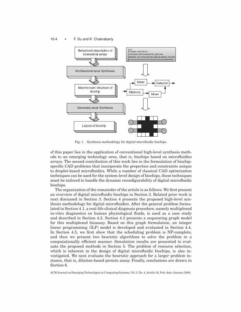
Much of recent research on CAD for microfluidic biochips has been focusedon device-level physical modeling of single components [Shapiro et al. 2003;Zeng and Korsmeyer 2004]. Although these modeling and simulation tools fa-cilitate the physical design of microfluidic devices, they are not adequate forsystem-level design. While top-down system-level design tools are now com-monplace in IC design, few such efforts have been reported for digital microflu-idics. Microfluidics-specific synthesis tools are needed to relieve biochip usersfrom the burden of manually optimizing a set of assays for increased through-out. These tools will allow users to describe bioassays at a high level of ab-straction; they will then map the behavioral description to the microfluidicarray and generate an optimized schedule of bioassay operations, the bindingof assay operations to resources, and the layout of the microfluidic biochip.Thus, the biochip user can concentrate on the development of the nano- andmicroscale bioassays, leaving implementation details to the synthesis tools.Motivated by the analogy between digital microfluidic biochips and digital in-tegrated circuits, we propose a system design methodology that attempts toapply classical high-level synthesis techniques to the biochip design, and thusspeed up the design cycle and reduce human effort. Figure 1 illustrates theproposed approach. The synthesis of a digital microfluidic biochip can be di-vided into two major phases, broadly referred to as high-level synthesis (i.e.,architectural-level synthesis) and geometry-level synthesis (i.e., physical de-sign). A behavioral model for a biochemical assay is first obtained from theprotocol for that assay. Next, high-level synthesis is used to generate a macro-scopic structure of the biochip; this structure is analogous to a structural RTLmodel in electronic CAD. This macroscopic model provides an assignment ofassay functions to biochip resources, as well as a mapping of assay functions totime-steps, based in part on the dependencies between them. Finally, geometry-level synthesis creates a physical representation at the geometrical level, thatis, the final layout of the biochip consisting of the configuration of the microflu-idic array, locations of reservoirs and dispensing ports, and other geometricdetails.
In this article, we focus on the high-level synthesis problem, that is, thescheduling of assay functions under resource constraints. The first contribution
ACM Journal on Emerging Technologies in Computing Systems, Vol. 3, No. 4, Article 16, Pub. date: January 2008.
16:4 • F. Su and K. Chakrabarty
Fig. 1. Synthesis methodology for digital microfluidic biochips.
of this paper lies in the application of conventional high-level synthesis meth-ods to an emerging technology area, that is, biochips based on microfluidicsarrays. The second contribution of this work lies in the formulation of biochip-specific CAD problems that incorporate the properties and constraints uniqueto droplet-based microfluidics. While a number of classical CAD optimizationtechniques can be used for the system-level design of biochips, these techniquesmust be tailored to handle the dynamic reconfigurability of digital microfluidicbiochips.
The organization of the remainder of the article is as follows. We first presentan overview of digital microfluidic biochips in Section 2. Related prior work isnext discussed in Section 3. Section 4 presents the proposed high-level syn-thesis methodology for digital microfluidics. After the general problem formu-lated in Section 4.1, a real-life clinical diagnosis procedure, namely multiplexedin-vitro diagnostics on human physiological fluids, is used as a case studyand described in Section 4.2. Section 4.3 presents a sequencing graph modelfor this multiplexed bioassay. Based on this graph formulation, an integerlinear programming (ILP) model is developed and evaluated in Section 4.4.In Section 4.5, we first show that the scheduling problem is NP-complete,and then we present two heuristic algorithms to solve the problem in acomputationally efficient manner. Simulation results are presented to eval-uate the proposed methods in Section 5. The problem of resource selection,which is inherent in the design of digital microfluidic biochips, is also in-vestigated. We next evaluate the heuristic approach for a larger problem in-stance, that is, dilution-based protein assay. Finally, conclusions are drawn inSection 6.
ACM Journal on Emerging Technologies in Computing Systems, Vol. 3, No. 4, Article 16, Pub. date: January 2008.
High-Level Synthesis of Digital Microfluidic Biochips • 16:5
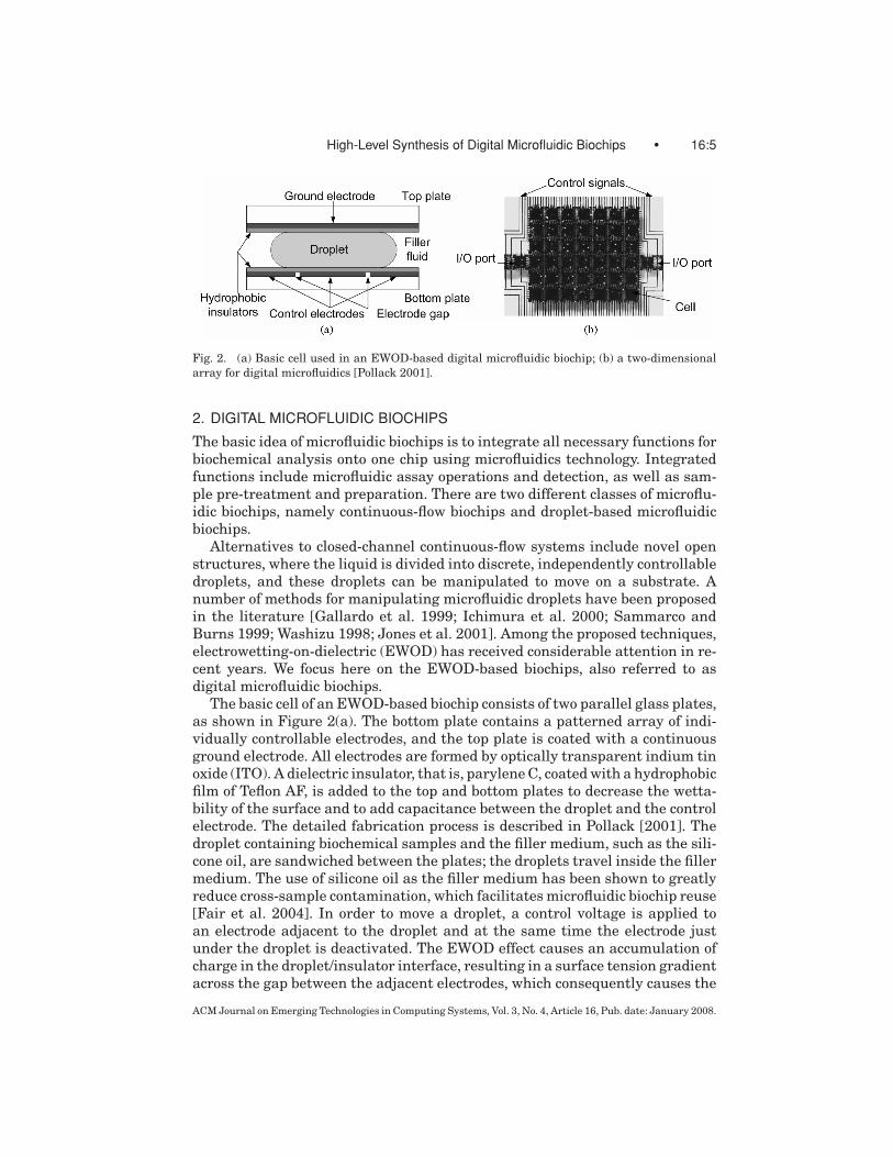
Fig. 2. (a) Basic cell used in an EWOD-based digital microfluidic biochip; (b) a two-dimensionalarray for digital microfluidics [Pollack 2001].
2. DIGITAL MICROFLUIDIC BIOCHIPS
The basic idea of microfluidic biochips is to integrate all necessary functions forbiochemical analysis onto one chip using microfluidics technology. Integratedfunctions include microfluidic assay operations and detection, as well as sam-ple pre-treatment and preparation. There are two different classes of microflu-idic biochips, namely continuous-flow biochips and droplet-based microfluidicbiochips.
Alternatives to closed-channel continuous-flow systems include novel openstructures, where the liquid is divided into discrete, independently controllabledroplets, and these droplets can be manipulated to move on a substrate. Anumber of methods for manipulating microfluidic droplets have been proposedin the literature [Gallardo et al. 1999; Ichimura et al. 2000; Sammarco andBurns 1999; Washizu 1998; Jones et al. 2001]. Among the proposed techniques,electrowetting-on-dielectric (EWOD) has received considerable attention in re-cent years. We focus here on the EWOD-based biochips, also referred to asdigital microfluidic biochips.
The basic cell of an EWOD-based biochip consists of two parallel glass plates,as shown in Figure 2(a). The bottom plate contains a patterned array of indi-vidually controllable electrodes, and the top plate is coated with a continuousground electrode. All electrodes are formed by optically transparent indium tinoxide (ITO). A dielectric insulator, that is, parylene C, coated with a hydrophobicfilm of Teflon AF, is added to the top and bottom plates to decrease the wetta-bility of the surface and to add capacitance between the droplet and the controlelectrode. The detailed fabrication process is described in Pollack [2001]. Thedroplet containing biochemical samples and the filler medium, such as the sili-cone oil, are sandwiched between the plates; the droplets travel inside the fillermedium. The use of silicone oil as the filler medium has been shown to greatlyreduce cross-sample contamination, which facilitates microfluidic biochip reuse[Fair et al. 2004]. In order to move a droplet, a control voltage is applied toan electrode adjacent to the droplet and at the same time the electrode justunder the droplet is deactivated. The EWOD effect causes an accumulation ofcharge in the droplet/insulator interface, resulting in a surface tension gradientacross the gap between the adjacent electrodes, which consequently causes the
ACM Journal on Emerging Technologies in Computing Systems, Vol. 3, No. 4, Article 16, Pub. date: January 2008.
16:6 • F. Su and K. Chakrabarty
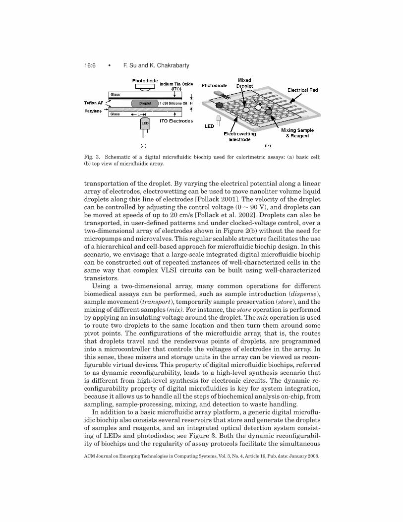
Fig. 3. Schematic of a digital microfluidic biochip used for colorimetric assays: (a) basic cell;(b) top view of microfluidic array.
transportation of the droplet. By varying the electrical potential along a lineararray of electrodes, electrowetting can be used to move nanoliter volume liquiddroplets along this line of electrodes [Pollack 2001]. The velocity of the dropletcan be controlled by adjusting the control voltage (0 ∼ 90 V), and droplets canbe moved at speeds of up to 20 cm/s [Pollack et al. 2002]. Droplets can also betransported, in user-defined patterns and under clocked-voltage control, over atwo-dimensional array of electrodes shown in Figure 2(b) without the need formicropumps and microvalves. This regular scalable structure facilitates the useof a hierarchical and cell-based approach for microfluidic biochip design. In thisscenario, we envisage that a large-scale integrated digital microfluidic biochipcan be constructed out of repeated instances of well-characterized cells in thesame way that complex VLSI circuits can be built using well-characterizedtransistors.
Using a two-dimensional array, many common operations for differentbiomedical assays can be performed, such as sample introduction (dispense),sample movement (transport), temporarily sample preservation (store), and themixing of different samples (mix). For instance, the store operation is performedby applying an insulating voltage around the droplet. The mix operation is usedto route two droplets to the same location and then turn them around somepivot points. The configurations of the microfluidic array, that is, the routesthat droplets travel and the rendezvous points of droplets, are programmedinto a microcontroller that controls the voltages of electrodes in the array. Inthis sense, these mixers and storage units in the array can be viewed as recon-figurable virtual devices. This property of digital microfluidic biochips, referredto as dynamic reconfigurability, leads to a high-level synthesis scenario thatis different from high-level synthesis for electronic circuits. The dynamic re-configurability property of digital microfluidics is key for system integration,because it allows us to handle all the steps of biochemical analysis on-chip, fromsampling, sample-processing, mixing, and detection to waste handling.
In addition to a basic microfluidic array platform, a generic digital microflu-idic biochip also consists several reservoirs that store and generate the dropletsof samples and reagents, and an integrated optical detection system consist-ing of LEDs and photodiodes; see Figure 3. Both the dynamic reconfigurabil-ity of biochips and the regularity of assay protocols facilitate the simultaneous
ACM Journal on Emerging Technologies in Computing Systems, Vol. 3, No. 4, Article 16, Pub. date: January 2008.
High-Level Synthesis of Digital Microfluidic Biochips • 16:7
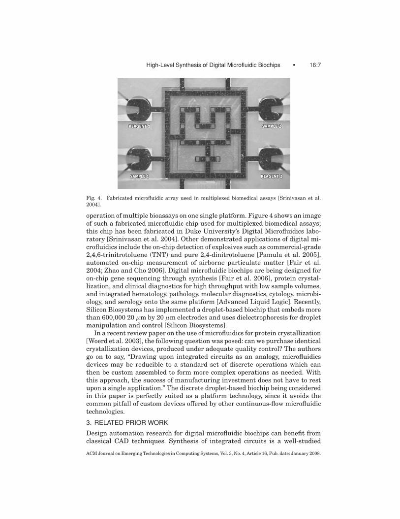
Fig. 4. Fabricated microfluidic array used in multiplexed biomedical assays [Srinivasan et al.2004].
operation of multiple bioassays on one single platform. Figure 4 shows an imageof such a fabricated microfluidic chip used for multiplexed biomedical assays;this chip has been fabricated in Duke University’s Digital Microfluidics labo-ratory [Srinivasan et al. 2004]. Other demonstrated applications of digital mi-crofluidics include the on-chip detection of explosives such as commercial-grade2,4,6-trinitrotoluene (TNT) and pure 2,4-dinitrotoluene [Pamula et al. 2005],automated on-chip measurement of airborne particulate matter [Fair et al.2004; Zhao and Cho 2006]. Digital microfluidic biochips are being designed foron-chip gene sequencing through synthesis [Fair et al. 2006], protein crystal-lization, and clinical diagnostics for high throughput with low sample volumes,and integrated hematology, pathology, molecular diagnostics, cytology, microbi-ology, and serology onto the same platform [Advanced Liquid Logic]. Recently,Silicon Biosystems has implemented a droplet-based biochip that embeds morethan 600,000 20 µm by 20 µm electrodes and uses dielectrophoresis for dropletmanipulation and control [Silicon Biosystems].
In a recent review paper on the use of microfluidics for protein crystallization[Woerd et al. 2003], the following question was posed: can we purchase identicalcrystallization devices, produced under adequate quality control? The authorsgo on to say, “Drawing upon integrated circuits as an analogy, microfluidicsdevices may be reducible to a standard set of discrete operations which canthen be custom assembled to form more complex operations as needed. Withthis approach, the success of manufacturing investment does not have to restupon a single application.” The discrete droplet-based biochip being consideredin this paper is perfectly suited as a platform technology, since it avoids thecommon pitfall of custom devices offered by other continuous-flow microfluidictechnologies.
3. RELATED PRIOR WORK
Design automation research for digital microfluidic biochips can benefit fromclassical CAD techniques. Synthesis of integrated circuits is a well-studied
ACM Journal on Emerging Technologies in Computing Systems, Vol. 3, No. 4, Article 16, Pub. date: January 2008.
16:8 • F. Su and K. Chakrabarty
problem [De Micheli 1994] and advances in high-level and logic synthesis tech-niques continue even today [Camposano 1996]. Walker and Camposano [1991]provides an excellent survey of high-level synthesis work. Driven by the need tointegrate digital and analog functions in a mixed-signal circuit, analog circuitsynthesis has also gained momentum in recent years [Antao and Brodersen1992].
MEMS design is a relatively young field compared to IC design. Since theconcept of special CAD systems for MEMS was first proposed at Transducer ’87[Senturia 1987], several research groups have reported significant progress inthis area, and a number of commercial MEMS CAD tools are now available[Fedder and Jing 1999; De and Aluru 2003]. Many of these tools are fo-cused solely on the modeling of thermal and electro/mechanical properties.Recently, synthesis tools for MEMS have also been developed [Mukherjee andFedder 1998]. However, because of the differences in actuation methods be-tween MEMS and digital microfluidics, they cannot be directly used for thedesign of microfluidic biochips.
While MEMS design tools have reached a certain level of maturity, CADtools for biochips are still in their infancy. Some design automation techniqueshave been proposed for DNA probe arrays [Kahng et al. 2003]; however, thedigital microfluidic biochips described in this article are more versatile andcomplex than DNA arrays. For microfluidic biochips, some commercial compu-tational fluid dynamics (CFD) tools, such as CFD-ACE+ from CFD ResearchCorporation and FlumeCAD from Coventor, Inc. support 3D simulation of mi-crofluidic transport. A recent release of CoventorWare from Coventor, Inc. in-cludes microfluidic behavioral models to allow top-down system-level design[CoventorWare]. Pfeiffer et al. [2004] also presented a synthesis approachfor multiplexed capillary electrophoresis (CE) separation microchips. Unfor-tunately, these CAD tools are only able to deal with continuous flow systems,and they are therefore inadequate for the design of digital microfluidic biochips.Recently behavioral modeling for droplet-based microfluidic systems has beeninvestigated [Bohringer 2004; Griffith and Akella 2004; Ding et al. 2001]. Inearly work in this area, Ding et al. [2001] presented an architectural designand optimization methodology for 2-D arrays based on electrowetting. Integerlinear programming was used to minimize the bioassay processing time in Dinget al. [2001]. Unfortunately, this model, while useful for real-time polymerasechain reaction (PCR), does not scale well for larger problems. Moreover, thisearly work is more for post-layout optimization, where droplet pathways andlocations for storage, mixing, and splitting operations need to be predefinedby the user. Priority scheduling in digital microfluidic biochips was proposedin Ricketts et al. [2006]. Reconfiguration and defect tolerance techniques forbiochips were described in Su and Chakrabarty [2006]. A comprehensive cost-effective test methodology for digital microfluidic systems was proposed in Suet al. [2004]. Based on the detection mechanism, an efficient concurrent testingscheme that interleaves test application with a set of bioassays was proposed inSu et al. [2004]. These testing techniques can be further integrated with system-level synthesis tools to facilitate design-for-test (DFT) for digital microfluidicbiochips.
ACM Journal on Emerging Technologies in Computing Systems, Vol. 3, No. 4, Article 16, Pub. date: January 2008.
High-Level Synthesis of Digital Microfluidic Biochips • 16:9
4. HIGH-LEVEL SYNTHESIS METHODOLOGY
4.1 Problem Formulation
The goal of a synthesis procedure is to select a design that minimizes a certaincost function under resource constraints. High-level synthesis for microfluidicbiochips can be viewed as the problem of scheduling assay functions and bind-ing them to a given number of resources so as to maximize parallelism, therebydecreasing response time. Conventional high-level synthesis methods can beleveraged for the emerging biochip domain. First, a well-defined droplet-basedassay protocol can be modeled by a sequencing graph as in the case of high-levelsynthesis for integrated circuits. By using discrete unit-volume droplets, a mi-crofluidic function can be reduced to a set of repeated basic operations, thatis, moving one unit of fluid (droplet) over one unit of instance (one electrodelength). This “digitization” method facilitates the implementation of many well-defined protocols for nano- and microscale bioassays on a microchip. A genericclass of microdroplet-based bioassay protocols that can be applied to digitalmicrofluidic biochips usually consists of the following steps: 1) dispensing sam-ple/reagent droplets into the microfluidic array; 2) transporting the dropletsto some locations on the array for assays operations (e.g., mixing, dilution oroptical detection); 3) finally moving the droplets of assay products or wastesout of the array. We denote such a generic bioassay protocol as Passay and itscorresponding sequencing graph as G p.
We next formulate a scheduling problem, whose goal is to determine thestart times and stop times of all assay operations, subject to the precedenceconstraints imposed by the sequencing graph. Resource constraints also needto be satisfied for bioassay scheduling. Here we use the term resource binding torefer to the mapping of bioassay operations to available functional resources.In a valid schedule, assay operations that share a resource cannot executeconcurrently. Due to resource constraints, a resource binding may associateone functional resource with several assay operations of the same type; thisnecessitates resource sharing. Moreover, due to dynamic reconfigurability, wecan allow operations of different types, for example, mixing and storing, toshare the same microfluidic cells on the array during different time spans. Wealso note that there may be several types of resources for any given bioassayoperation. For example, a 2×2-array mixer, a 2×3-array mixer and a 2×4-arraymixer can be used for a droplet mixing operation [Paik et al. 2003]. These mixersdiffer in their areas as well as mixing times. In such cases, a resource selectionprocedure must be used.
Based on the above definitions, this leads us to the following optimizationproblem for high-level synthesis of digital microfluidic biochips:
HLS Bio. Given Passay (and its corresponding sequencing graph G p) and theavailable resources, determine a schedule of assays as well as an assignment ofassay operations to functional resources, such that the assay completion timeis minimized without any resource conflicts.
The minimization of the assay completion time is essential for environmen-tal monitoring applications where sensors can provide early warning. Real-time response is also necessary for surgery and neonatal clinical diagnostics.
ACM Journal on Emerging Technologies in Computing Systems, Vol. 3, No. 4, Article 16, Pub. date: January 2008.

16:10 • F. Su and K. Chakrabarty
Finally, biological samples are sensitive to the environment and to temperaturevariations, and it is difficult to maintain an optimal clinical or laboratory en-vironment on chip. For example, protein crystallization and high-throughputDNA sequencing (HTS) are two emerging applications of digital microfluidics,especially for concurrent fluid handling on a chip. In protein crystallization, alarge number of conditions, defined by different combinations of precipitants,diluents, and other reagents in various concentrations, must be evaluated forthe likelihood of the formation of protein crystals. Concurrent processing willallow the evaluation of these conditions rapidly and in parallel. HTS is a pro-cedure that is very useful for sequencing many different templates of DNAwith any number of primers. These operations can also be run in parallelon the same chip, reducing the time and cost associated with HTS. To en-sure the integrity of assay results, it is therefore desirable to minimize thetime that samples spend on-chip before assay results are obtained. Increasedthroughput also improves operational reliability. Long assay durations implythat high actuation voltages need to be maintained on some electrodes, whichaccelerate insulator degradation and dielectric breakdown, reducing the num-ber of assays that can be performed on a chip during its lifetime. Therefore,assay processing time must be minimized for both disposable and reusablebiochips.
Note that there are some key difference between the new problem HLS Bioand the high-level synthesis problem for digital circuits. The first results fromthe dynamic reconfigurability of digital microfluidic biochips. Unlike electroniccomponents in circuits, many microfluidic components (e.g., mixers and stor-age units) can be dynamically formed anywhere on a 2-D array. The dynamicreconfigurability provided by digital microfluidic biochips is in many ways simi-lar to the partial reconfiguration offered by Dynamically Reconfigurable FPGAs(DRFPGAs). However, the programmability of DRFPGAs is limited by the well-defined roles of interconnect and logic blocks. Interconnect cannot be used forstoring information, and logic blocks cannot be used for routing. In contrast,the digital microfluidic biochips offer significantly more programmability. Thecells in the microfluidic array can be used for storage, functional operations, aswell as for transporting fluid droplets.
Another major difference is that while conventional high-level synthesistargets pre-layout design, synthesis for biochip encompasses both pre- andpost-manufacture. This feature meets the increasing need for field programma-bility to support multiple concurrent assays on the same chip. Even for dis-posable biochip applications, reconfigurability is attractive since it facilitatesthe microfluidic array structure to be reconfigured for different assay appli-cations, thereby reducing product cost due to the possibility of high-volumemanufacturing.
In the following sections, we first use a real-life biochemical assay, namelymultiplexed in-vitro diagnostics, to illustrate the HLS Bio problem formula-tion. We then present algorithms for the high-level synthesis of digital mi-crofluidic biochips. Finally, we apply the proposed heuristic approach to a largerbiochemical application, namely, protein assay involving a series of on-chip di-lution steps.
ACM Journal on Emerging Technologies in Computing Systems, Vol. 3, No. 4, Article 16, Pub. date: January 2008.

High-Level Synthesis of Digital Microfluidic Biochips • 16:11
Fig. 5. Photos of different steps of a glucose assay carried out on a digital microfluidic biochip[Srinivasan et al. 2004].
4.2 Illustrative Example: Multiplexed In-Vitro Diagnostics on HumanPhysiological Fluids
The in-vitro measurement of glucose and other metabolites, such as lactate,glutamate, and pyruvate, in human physiological fluids is of great importancein clinical diagnosis of metabolic disorders. For instance, the change of regu-lar metabolic parameters in the patient’s blood can signal organ damage ordysfunction prior to observable microscopic cellular damages or other symp-toms. Protocols for enzyme-kinetic measurements of metabolites are suitablefor droplet-based microfluidics implementation. The feasibility of performing acolorimetric glucose assay on a digital microfluidic biochip has been successfullydemonstrated in experiments [Srinivasan et al. 2003, 2004].
The glucose assay performed on the biochip is based on Trinder’s reaction,a colorimetric enzyme-based method. The enzymatic reactions involved in theassay:
Glucose + H2O + O2Glucose Oxidase
−→ Gluconic Acid + H2O2
2H2O2 + 4-AAP + TOPS Peroxidase−→ Quinoneimine + 4H2O
In the presence of glucose oxidase, glucose can be enzymatically oxidizedto gluconic acid and hydrogen peroxide. Then, in the presence of peroxidase,the hydrogen peroxide reacts with 4-amino antipyrine (4-AAP) and N-ethyl-N-sulfopropyl-m-toluidine (TOPS) to form violet-colored quinoneimine, which hasan absorbance peak at 545 nm. Based on this colorimetric reaction, a completeglucose assay can be performed following three steps, namely, transportation,mixing, and optical detection, as shown in Figure 5. Sample droplets containingglucose and reagent droplets containing glucose oxidase, peroxidase, 4-AAP,and TOPS, are dispensed into the microfluidic array from droplet reservoirs.They are then transported towards a mixer where droplets of the sample andthe reagent are mixed together and the enzymatic reaction happens during themixing. A droplet of the product is moved to the location of the optical detector.The optical detection is performed using a green LED and a photodiode. The
ACM Journal on Emerging Technologies in Computing Systems, Vol. 3, No. 4, Article 16, Pub. date: January 2008.
16:12 • F. Su and K. Chakrabarty
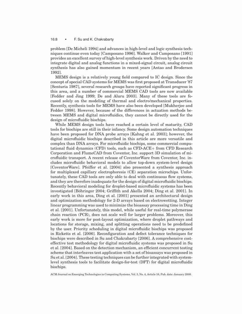
Fig. 6. One example of multiplexed in-vitro diagnostics.
glucose concentration can be detected from the absorbance, which is relatedto the concentration of colored quinoneimine. Experiments have shown thatthe results from the digital microfluidic biochip match well with the referencevalues obtained from conventional measurements [Srinivasan et al. 2004].
In addition to glucose assays, the detections of other metabolites such aslactate, glutamate and pyruvate in a digital microfluidic biochip have also beendemonstrated recently [Srinivasan et al. 2004]. Furthermore these assays canbe integrated together to form a multiplexed in-vitro diagnostics on differenthuman physiological fluids, which can be performed concurrently on a microflu-idic biochip.
4.3 Sequencing Graph Model
The behavioral description of an example of a multiplexed in-vitro diagnostics isshown in Figure 6. Four types of human physiological fluids—plasma, serum,urine, and saliva—are sampled and dispensed into the microfluidic biochip.Next each type of physiological fluid is assayed for glucose, lactate, pyruvate orglutamate measurement. For each enzymatic assay, the droplets containing thesuitably modified reagents (e.g., Glucose oxidase, Peroxidase, 4-AAP and TOPSfor glucose measurement) are dispensed into the microfluidic array from therelevant reservoirs. The result of each type of bioassays can be detected usinga dedicated optical absorbance measurement device.
An abstract model of a bioassay behavior at the architectural level can bedeveloped in terms of operations and the dependencies between them. We usethe sequencing graph model from high-level synthesis terminology [Micheli1994]. We assume that there are a total of nops operations. The sequencinggraph is acyclic and polar. There are two vertices, called source v0 and sink vk ,that present the first and last no-operation task, where k = nops + 1. Hence thesequencing graph G(V , E) has vertex set V = {vi: i = 0, 1, . . . , k} in one-to-onecorrespondence with the set of assay operations, and edge set E = {(vi, vj ):i, j = 0, 1, . . . , k} representing dependencies. With each node vi, we associatea weight d (vi), which denotes the time taken for operation vi. The details ofthese operations and the resources that these operations use are as follows. (Weassume that m types of physiological fluids are assayed for n types of enzymaticmeasurements.)
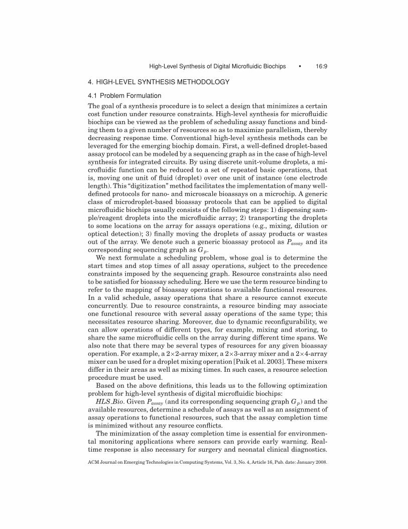
Input Operations. These operations consist of the generation of the dropletsof samples (Si, i = 1, . . . , m) or reagents (Ri, i = 1, . . . , n) from the on-chipreservoir, which are then dispensed into the microfluidic array. These operationsare represented using the nodes shown in Figure 7. There are m + n types
ACM Journal on Emerging Technologies in Computing Systems, Vol. 3, No. 4, Article 16, Pub. date: January 2008.
High-Level Synthesis of Digital Microfluidic Biochips • 16:13
Fig. 7. Nodes representing the input operations.
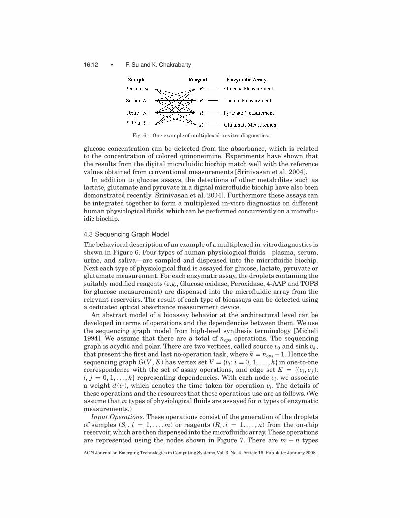
Fig. 8. On-chip reservoirs to store and dispense droplets [Ren and Fair 2002].
of input operations (denoted by Ii, i = 1, . . . , m + n), where I j , j = 1, . . . , mrepresents the generation and dispensing of droplets of sample Sj . Similarly,I j+m, j = 1, . . . , n, denotes the operation for reagent R j .
Assumption 1. We assume that the time required to generate and dispensedroplets from the reservoir is determined mainly by the system parameters,such as the aspect ratio of the channel gap to electrode gap [Ren and Fair 2002].The properties of the fluid have little impact on the input operation time. Thisassumption has been verified by experimental data [Ren and Fair 2002].
Assumption 1 implies that the weights of the input operation nodes are equal.That is, there is no difference between the operation times required for generat-ing and dispensing different samples and reagents. Experiments indicate thatdroplet generation and dispensing takes 2 seconds [Ren and Fair 2002]. There-fore, we set one unit of time to 2 seconds, and let d (Ii) = 1 unit of time, wherei = 1, . . . , m + n.
In order to avoid unexpected contamination between different samples andreagents, at least one reservoir is needed for each type of fluid. We assume thatthere are Nr reservoirs for each type of fluid (Nr ≥ 1). Moreover, these reservoirsbelong to the category of non-reconfigurable resources, that is, they are fixedafter design and fabrication, as shown in Figure 8 [Ren and Fair 2002].
Mixing Operation. In order to perform the required enzymatic assay, dropletsof samples need to be mixed with droplets of reagents on the microfluidic array.
Assumption 2. The viscosities of the different reagents are almost the samebecause they are highly diluted by the same fluid, such as H2O, before dispens-ing [Srinivasan et al. 2003, 2004].Thus the time required for complete mixingmainly depends on the viscosity of the sample. For the same sample, the mixingtime can be considered to be the same for different reagents.
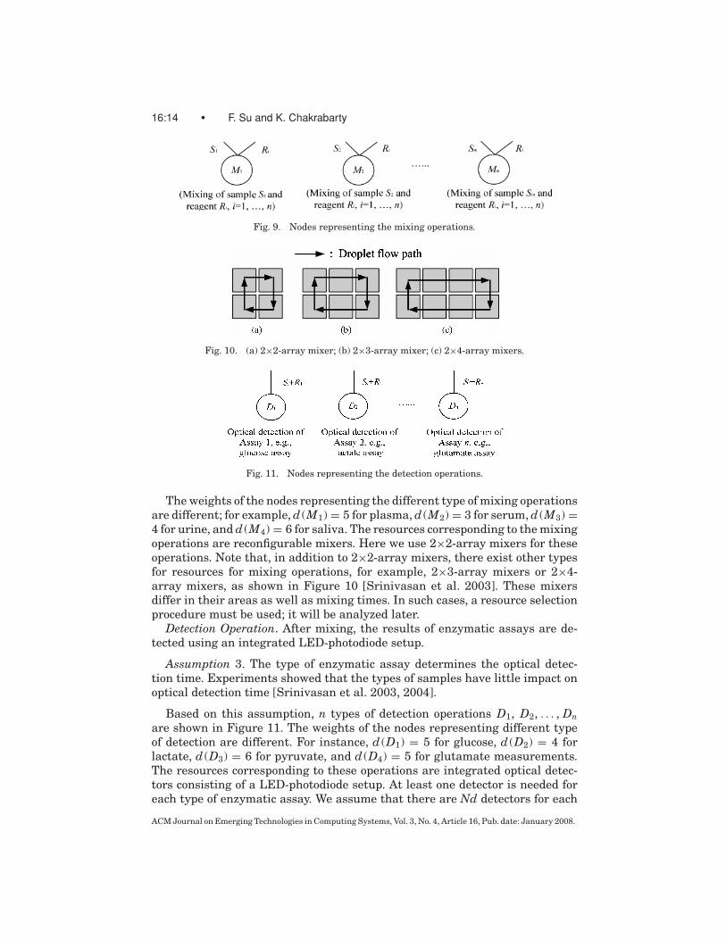
Based on this assumption, which is supported by available experimentaldata, we define m types of mixing operations M1, M2, . . . , Mm, represented bythe nodes shown in Figure 9.
ACM Journal on Emerging Technologies in Computing Systems, Vol. 3, No. 4, Article 16, Pub. date: January 2008.
16:14 • F. Su and K. Chakrabarty
Fig. 9. Nodes representing the mixing operations.
Fig. 10. (a) 2×2-array mixer; (b) 2×3-array mixer; (c) 2×4-array mixers.
Fig. 11. Nodes representing the detection operations.
The weights of the nodes representing the different type of mixing operationsare different; for example, d (M1) = 5 for plasma, d (M2) = 3 for serum, d (M3) =4 for urine, and d (M4) = 6 for saliva. The resources corresponding to the mixingoperations are reconfigurable mixers. Here we use 2×2-array mixers for theseoperations. Note that, in addition to 2×2-array mixers, there exist other typesfor resources for mixing operations, for example, 2×3-array mixers or 2×4-array mixers, as shown in Figure 10 [Srinivasan et al. 2003]. These mixersdiffer in their areas as well as mixing times. In such cases, a resource selectionprocedure must be used; it will be analyzed later.
Detection Operation. After mixing, the results of enzymatic assays are de-tected using an integrated LED-photodiode setup.
Assumption 3. The type of enzymatic assay determines the optical detec-tion time. Experiments showed that the types of samples have little impact onoptical detection time [Srinivasan et al. 2003, 2004].
Based on this assumption, n types of detection operations D1, D2, . . . , Dnare shown in Figure 11. The weights of the nodes representing different typeof detection are different. For instance, d (D1) = 5 for glucose, d (D2) = 4 forlactate, d (D3) = 6 for pyruvate, and d (D4) = 5 for glutamate measurements.The resources corresponding to these operations are integrated optical detec-tors consisting of a LED-photodiode setup. At least one detector is needed foreach type of enzymatic assay. We assume that there are Nd detectors for each
ACM Journal on Emerging Technologies in Computing Systems, Vol. 3, No. 4, Article 16, Pub. date: January 2008.
High-Level Synthesis of Digital Microfluidic Biochips • 16:15
Fig. 12. Sequencing graph model for a multiplexed in-vitro diagnostics.
type of assay (Nd ≥ 1). These resources also belong to the category of non-reconfigurable resources.
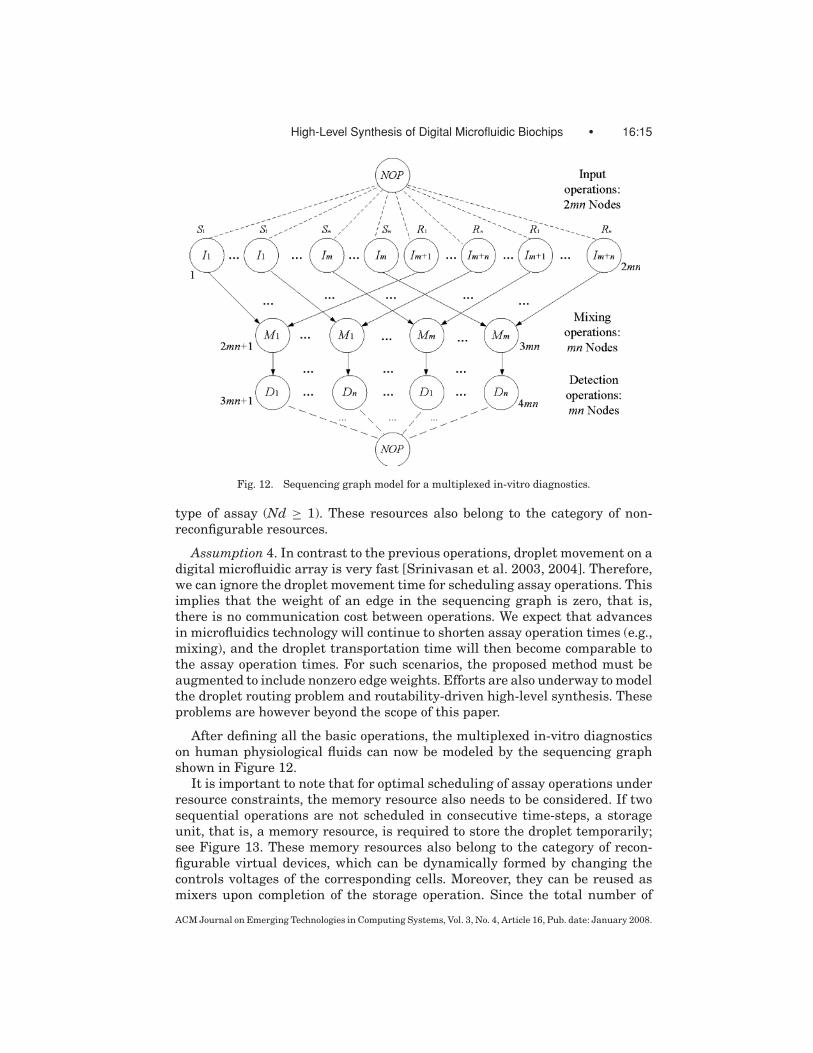
Assumption 4. In contrast to the previous operations, droplet movement on adigital microfluidic array is very fast [Srinivasan et al. 2003, 2004]. Therefore,we can ignore the droplet movement time for scheduling assay operations. Thisimplies that the weight of an edge in the sequencing graph is zero, that is,there is no communication cost between operations. We expect that advancesin microfluidics technology will continue to shorten assay operation times (e.g.,mixing), and the droplet transportation time will then become comparable tothe assay operation times. For such scenarios, the proposed method must beaugmented to include nonzero edge weights. Efforts are also underway to modelthe droplet routing problem and routability-driven high-level synthesis. Theseproblems are however beyond the scope of this paper.
After defining all the basic operations, the multiplexed in-vitro diagnosticson human physiological fluids can now be modeled by the sequencing graphshown in Figure 12.
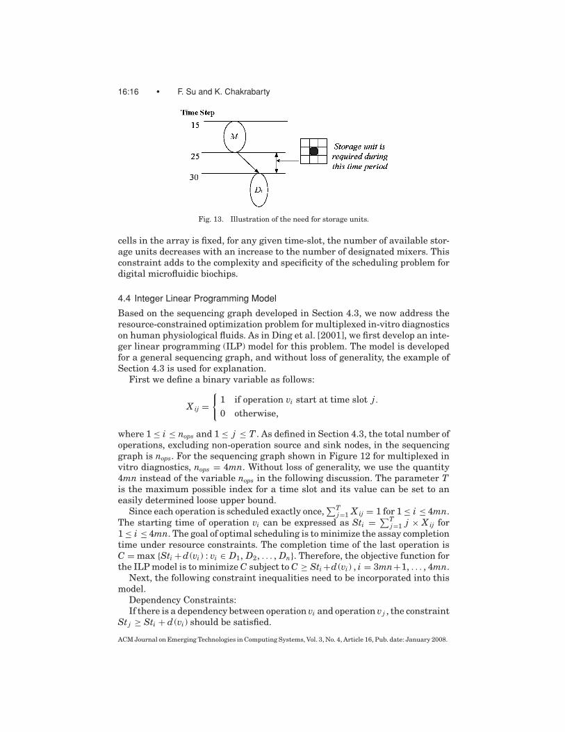
It is important to note that for optimal scheduling of assay operations underresource constraints, the memory resource also needs to be considered. If twosequential operations are not scheduled in consecutive time-steps, a storageunit, that is, a memory resource, is required to store the droplet temporarily;see Figure 13. These memory resources also belong to the category of recon-figurable virtual devices, which can be dynamically formed by changing thecontrols voltages of the corresponding cells. Moreover, they can be reused asmixers upon completion of the storage operation. Since the total number of
ACM Journal on Emerging Technologies in Computing Systems, Vol. 3, No. 4, Article 16, Pub. date: January 2008.
16:16 • F. Su and K. Chakrabarty
Fig. 13. Illustration of the need for storage units.
cells in the array is fixed, for any given time-slot, the number of available stor-age units decreases with an increase to the number of designated mixers. Thisconstraint adds to the complexity and specificity of the scheduling problem fordigital microfluidic biochips.
4.4 Integer Linear Programming Model
Based on the sequencing graph developed in Section 4.3, we now address theresource-constrained optimization problem for multiplexed in-vitro diagnosticson human physiological fluids. As in Ding et al. [2001], we first develop an inte-ger linear programming (ILP) model for this problem. The model is developedfor a general sequencing graph, and without loss of generality, the example ofSection 4.3 is used for explanation.
First we define a binary variable as follows:
X ij =!
1 if operation vi start at time slot j .0 otherwise,
where 1 ≤ i ≤ nops and 1 ≤ j ≤ T . As defined in Section 4.3, the total number ofoperations, excluding non-operation source and sink nodes, in the sequencinggraph is nops. For the sequencing graph shown in Figure 12 for multiplexed invitro diagnostics, nops = 4mn. Without loss of generality, we use the quantity4mn instead of the variable nops in the following discussion. The parameter Tis the maximum possible index for a time slot and its value can be set to aneasily determined loose upper bound.
Since each operation is scheduled exactly once,"T
j=1 X ij = 1 for 1 ≤ i ≤ 4mn.The starting time of operation vi can be expressed as Sti =
"Tj=1 j × X ij for
1 ≤ i ≤ 4mn. The goal of optimal scheduling is to minimize the assay completiontime under resource constraints. The completion time of the last operation isC = max {Sti + d (vi) : vi ∈ D1, D2, . . . , Dn}. Therefore, the objective function forthe ILP model is to minimize C subject to C ≥ Sti +d (vi) , i = 3mn+1, . . . , 4mn.
Next, the following constraint inequalities need to be incorporated into thismodel.
Dependency Constraints:If there is a dependency between operation vi and operation vj , the constraint
St j ≥ Sti + d (vi) should be satisfied.
ACM Journal on Emerging Technologies in Computing Systems, Vol. 3, No. 4, Article 16, Pub. date: January 2008.

High-Level Synthesis of Digital Microfluidic Biochips • 16:17
Resource Constraints:Reservoirs/Dispensing Ports. We assume that Nr reservoirs/dispensing ports
are assigned to each type of fluid. Without loss of generality, we set Nr = 1,that is, there are m + n reservoirs/dispensing ports attached to the microfluidicarray, where m reservoirs store and generate the sample droplets, and theothers are for n types of assay reagents. This constraint is expressed as:
!
i:vi∈I1
X ij ≤ 1,!
i:vi∈I2
X ij ≤ 1, . . .!
i:vi∈Im+n
X ij ≤ 1 : 1 ≤ j ≤ T.
Reconfigurable Mixers and Reconfigurable Storage Units. The mix opera-tion is performed on a reconfigurable mixer, which serves a virtual device. Inaddition, there might exist other virtual devices, for example, reconfigurablestorage units, which are formed to temporarily store the droplet between twosequential operations. The total number of the available virtual devices is con-strained by the size of a microfluidic array. We model this resource relationshipas follows:
Nmixer( j ) + β · Nmemory( j ) ≤ Na for 1 ≤ j ≤ T,
where Nmixer( j ) is the number of mixers needed at time slot j , Nmemory( j ) isthe number of storage units needed at time slot j , and Na is a value determinedby the array size. In fact, Na is determined from the size of the microfluidicarray, described in terms of the number of cells. It is normalized to the numberof mixers of a given size that can be accommodated on the array. We also assumethat the size of a storage unit is a fraction β of the size of a mixer. If a 2×2-array mixer is the only type of resource used for mixing, β = 0.25. Note thatthe overheads due to isolation cells and cells used for droplet transportationare not included here. These overheads are modeled more appropriately duringmodule placement [Su and Chakrabarty 2006] and droplet routing [Su et al.2006], which are beyond the scope of this paper. An appropriate value of β
can be easily obtained for other types of mixers or if taking isolation cells intoaccount. Finally, the ILP model does not handle mixers of unequal sizes, thusthe problem of resource module selection is not addressed here. Instead, it isseparately addressed in Section 5.2.
An operation vi is executed at time slot j when" j
l= j−d (vi )+1 X il = 1. There-fore, the number of mixers used in time slot j is as follows:
Nmixer( j ) =!
{i:vi∈M1,M2,...Mm}
j!
l= j−d (vi )+1
X il .
In order to find the number of storage units (memory) needed at time slot j ,we define a binary variable as follows:
Mij =#
1 if storage unit i is needed at time slot j .0 otherwise
where memory (storage unit) i is assigned to the edge between vertex vi and itsdirected successor vertex vk , 1 ≤ i ≤ 3mn and 1 ≤ j ≤ T . Then Nmemory( j ) ="3mn
i=1 Mij. To determine Mij, we set Aij = 1 −" j
l=1 X il , that is, Aij is 1 only
ACM Journal on Emerging Technologies in Computing Systems, Vol. 3, No. 4, Article 16, Pub. date: January 2008.

16:18 • F. Su and K. Chakrabarty
Fig. 14. Variables in different time steps.
before operation vi starts; Bij =! j
l= j−d (vi )+1 X il , that is, Bij is 1 only when vi isactive; Cij =
! jl=1 X kl , that is, Cij is 1 only when vk starts. Note that the above
definition of Cij only considers cases where each vertex has only one successor.This is indeed the case for many multiplexed bioassay protocols that we haveencountered. The definition of Cij will need to be modified to handle the casesof multiple successors. For the protein assay considered later in this article,which includes dilution and splitting step leading to multiple successors, we donot use the ILP method. It can be easily seen that Mij + Aij + Bij + Cij = 1; seeFigure 14. Therefore, Mij = 1 − Aij − Bij − Cij =
! j−d (vi )l=1 X il −
! jl=1 X kl .
Optical Detectors. We assign Nd detectors to each enzymatic assay; for ex-ample, Nd = 1. Similar to the constraint for reservoir/dispensing ports, thisfunctional resource constraint can be modeled as follows:
"
i:vi∈D1
j"
l= j−d (vi )
X il ≤ 1, . . . ,"
i:vi∈Dn1
j"
l= j−d (vi )
X il ≤ 1 : 1 ≤ j ≤ T.
We have now developed the ILP model for Passay using multiplexed bioas-say as an illustrative example. The general ILP model is shown in Figure 15.The complexity of this formulated ILP model for the scheduling problem isO(mnT) in the number of variables and O(mn + Tm + Tn) in the number ofconstraints.
This ILP model is evaluated for a problem of modest size. For instance,plasma and serum are sampled and assayed for glucose, lactate and pyruvatemeasurements; that is, m = 2, n = 3, as shown in Figure 16. We assume Nr =Nd = 1, and Na = 4. We use a popular public domain ILP solver called lpsolve[Berkelaar]. It took over 3 hours of CPU time on a 1.0 GHz Pentium-III PC with256 MB of RAM. The optimal schedule for this multiplexed biomedical assay isshown in Figure 17. The completion time for the whole assay is 17 time-slots;that is, 34 seconds.
4.5 Heuristics for the Scheduling Problem
The scheduling problem being studied here is equivalent to the resource-constrained scheduling problem with non-uniform weights of operation nodes,which has been proven to be NP-complete [Garey and Johnson 1979; Kwok
ACM Journal on Emerging Technologies in Computing Systems, Vol. 3, No. 4, Article 16, Pub. date: January 2008.

High-Level Synthesis of Digital Microfluidic Biochips • 16:19
Fig. 15. Integer linear programming (ILP) model for the scheduling problem.
Fig. 16. Sequencing graph corresponding to one instance of multiplexed diagnostics.
and Ahmad 1999]. In order to solve this problem in a computationally efficientmanner for large instances, we develop heuristics in this section.
Modified List Scheduling Algorithm. This heuristic extends the well-knownList Scheduling algorithm [De Micheli 1994]. The pseudocode in Figure 18 il-lustrates how the list scheduling algorithm from the literature is modified tohandle reconfigurable resources such as mixers and storage units. Compared
ACM Journal on Emerging Technologies in Computing Systems, Vol. 3, No. 4, Article 16, Pub. date: January 2008.

16:20 • F. Su and K. Chakrabarty
Fig. 17. Optimal schedule obtained using the ILP model.
Fig. 18. Pseudocode for the modified list scheduling algorithm.
ACM Journal on Emerging Technologies in Computing Systems, Vol. 3, No. 4, Article 16, Pub. date: January 2008.
High-Level Synthesis of Digital Microfluidic Biochips • 16:21
Fig. 19. An example to illustrate the necessity of rescheduling.
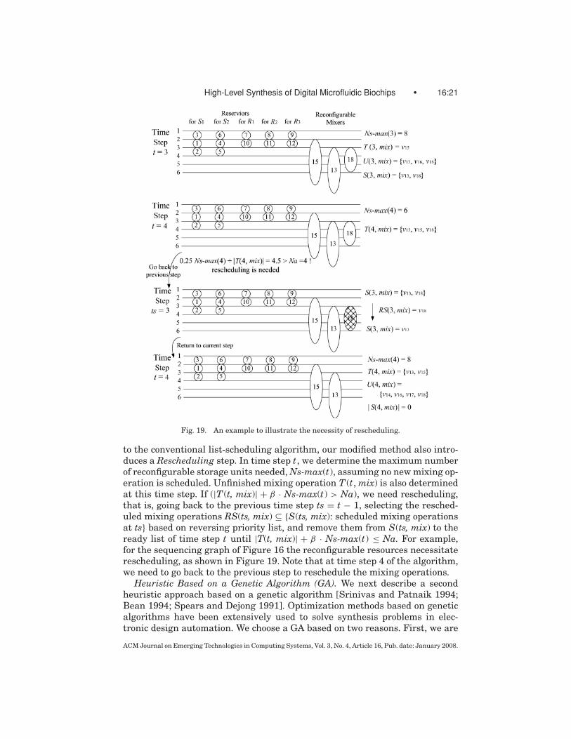
to the conventional list-scheduling algorithm, our modified method also intro-duces a Rescheduling step. In time step t, we determine the maximum numberof reconfigurable storage units needed, Ns-max(t), assuming no new mixing op-eration is scheduled. Unfinished mixing operation T (t, mix) is also determinedat this time step. If (|T (t, mix)| + β · Ns-max(t) > Na), we need rescheduling,that is, going back to the previous time step ts = t − 1, selecting the resched-uled mixing operations RS(ts, mix) ⊆ {S(ts, mix): scheduled mixing operationsat ts} based on reversing priority list, and remove them from S(ts, mix) to theready list of time step t until |T(t, mix)| + β · Ns-max(t) ≤ Na. For example,for the sequencing graph of Figure 16 the reconfigurable resources necessitaterescheduling, as shown in Figure 19. Note that at time step 4 of the algorithm,we need to go back to the previous step to reschedule the mixing operations.
Heuristic Based on a Genetic Algorithm (GA). We next describe a secondheuristic approach based on a genetic algorithm [Srinivas and Patnaik 1994;Bean 1994; Spears and Dejong 1991]. Optimization methods based on geneticalgorithms have been extensively used to solve synthesis problems in elec-tronic design automation. We choose a GA based on two reasons. First, we are
ACM Journal on Emerging Technologies in Computing Systems, Vol. 3, No. 4, Article 16, Pub. date: January 2008.

16:22 • F. Su and K. Chakrabarty
Fig. 20. Pseudocode for Genetic Algorithm-based heuristic approach.
targeting a multiobjective optimization problem for which researchers haveoften used GAs by formulating the problem in terms of multipriority optimiza-tions. The primary objective here is to minimize the bioassay completion time.A secondary goal is to optimize resource binding, in that number of functionalunits is minimized. Among various randomized search algorithms, GAs havebeen deemed in the literature to be appropriate for multiobjective optimiza-tion [Srinivas and Patnaik 1994; Aarts and Korst 1989]. Second, GA main-tains a pool of solutions instead of a single solution and allows communica-tion between solutions via crossover and mutation. In this way, GA is betterequipped to escape the local minima and use information from previous moves.Results in Section 5 showed GA leads to lower completion time comparedto the modified list-scheduling algorithm. The pseudocode for this GA-basedheuristic approach is shown in Figure 20. The details of this procedure are asfollows.
Representation of Chromosome. A robust representation technique calledrandom keys is used in this algorithm [Bean 1994]. The important feature ofrandom keys is that all offspring formed by crossover are feasible solutions.We interpret any random key vector as a feasible solution. Any crossover vec-tor is also feasible. This is ensured using an ad hoc design of a schedule con-struction procedure. Each chromosome in the population can be encoded as avector of random keys. In other words, Chromosome = {gene(1),. . . , gene(k),gene(k+1),. . . , gene(2k)}, where k is the number of operations, that is, k = 4 mnin our problem. Each gene is a random number sampled from [0, 1]. The firstk genes are used to indicate the operation priorities, that is, priority value ofoperation Pv(i) = gene(i), i =1 to k. The last k genes are used to determinethe delay time of the operations, which is calculated as follows: delay value ofoperation Dv(i) = d×MaxDur×gene(i + k), i =1 to k, where d is a constant.The parameter MaxDur denotes the maximum duration for all operations. Itshould be noted that these delay values are further modified in the scheduleconstruction procedure, such that any random number (gene(i +k)) can be usedto form the feasible solution.
ACM Journal on Emerging Technologies in Computing Systems, Vol. 3, No. 4, Article 16, Pub. date: January 2008.

High-Level Synthesis of Digital Microfluidic Biochips • 16:23
Fig. 21. Pseudocode for Phase I: scheduling input operations.
Schedule Construction Procedure. The goal of this ad-hoc procedure is toconstruct a feasible schedule, that is, satisfying dependency and resource con-straints, by using a vector of random numbers (chromosome). It consists ofthree phases: scheduling input operations, scheduling for mixing operationsand scheduling optical detection operations. As an illustration, the construc-tion procedure for Phase I is described in Figure 21, where we assume thatNr = 1.
Using these three phases, a feasible schedule satisfying both dependencyconstraints and resource constraints can be constructed by using any randomkey vector.
Evolution Strategy. In the genetic algorithm, reproduction and crossover op-erators tend to increase the quality of the populations and force convergence,while mutation opposes convergence and replaces genes lost during reproduc-tion and crossover [Srinivas and Patnaik 1994]. There exist many differenttypes of these operations in the literature. In our heuristic approach, theseevolutionary operators are defined as follows:
Reproduction. The chromosomes that have the highest fitness value, that is,the smallest completion time of the generated schedule, in the current popula-tion are copied to the next generation.
Crossover. Parameterized uniform crossover is employed in our algorithm[Spears and Dejong 1991]. In this crossover procedure, two parent chromosomesare chosen randomly from the old population. Then gene(i) of their offspring inthe new population is inherited (i.e., copied) from gene(i) of the father chromo-some with the probability P (e.g., P = 0.7), and from the mother chromosomewith the probability 1 − P .
Mutation. The new chromosomes of the population are generated randomlyto guarantee population diversity.
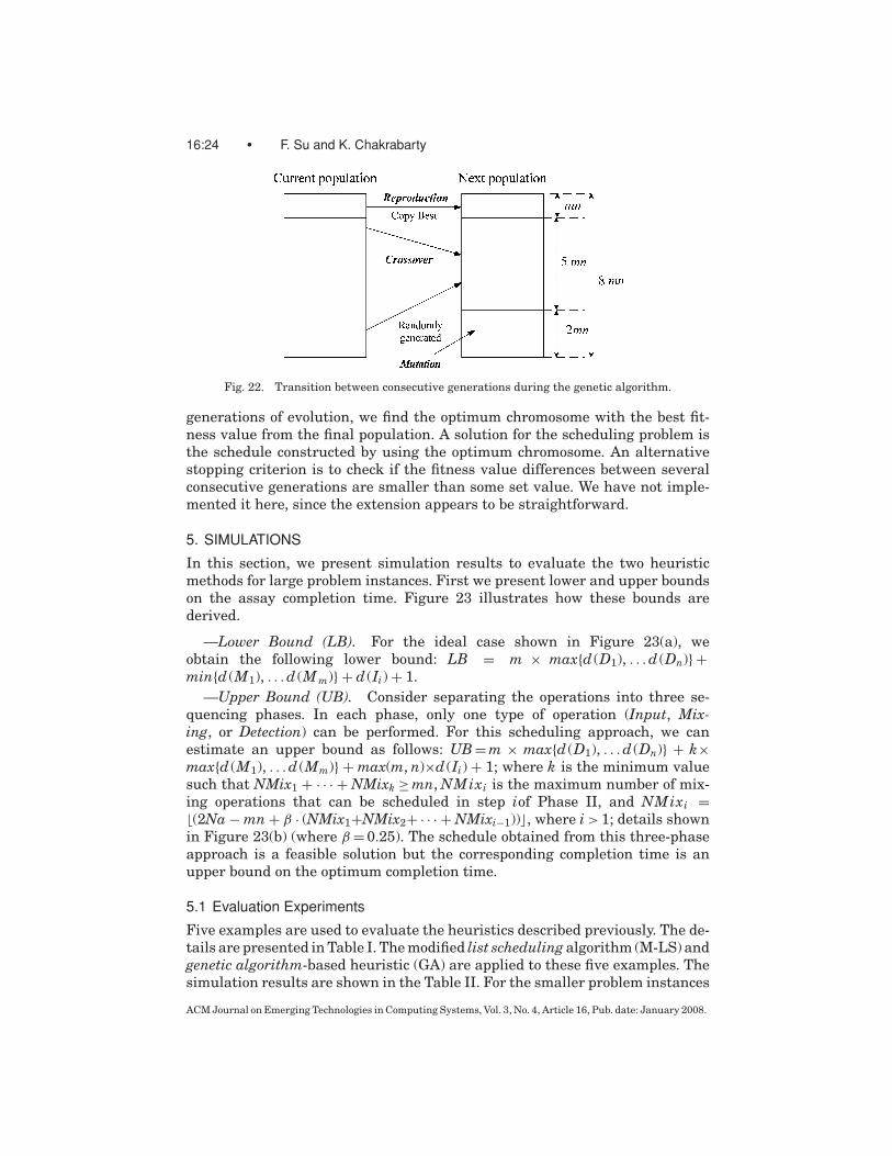
For our scheduling problem, there are 4mn operation nodes in the sequenc-ing graph. In the GA-based heuristic, we set the number of chromosomes inthe population to twice the number of operations, that is, 8mn. During evo-lution, the mn best chromosomes are reproduced into the next generation.A total of 5mn chromosomes in the new population are the offsprings gen-erated from the previous population. The remaining 2mn chromosomes arerandomly generated. This proportion is fine-tuned through experiments. Thetransition between two consecutive generations is shown in Figure 22. After G
ACM Journal on Emerging Technologies in Computing Systems, Vol. 3, No. 4, Article 16, Pub. date: January 2008.
16:24 • F. Su and K. Chakrabarty
Fig. 22. Transition between consecutive generations during the genetic algorithm.
generations of evolution, we find the optimum chromosome with the best fit-ness value from the final population. A solution for the scheduling problem isthe schedule constructed by using the optimum chromosome. An alternativestopping criterion is to check if the fitness value differences between severalconsecutive generations are smaller than some set value. We have not imple-mented it here, since the extension appears to be straightforward.
5. SIMULATIONS
In this section, we present simulation results to evaluate the two heuristicmethods for large problem instances. First we present lower and upper boundson the assay completion time. Figure 23 illustrates how these bounds arederived.
—Lower Bound (LB). For the ideal case shown in Figure 23(a), weobtain the following lower bound: LB = m × max{d (D1), . . . d (Dn)} +min{d (M1), . . . d (M m)} + d (Ii) + 1.
—Upper Bound (UB). Consider separating the operations into three se-quencing phases. In each phase, only one type of operation (Input, Mix-ing, or Detection) can be performed. For this scheduling approach, we canestimate an upper bound as follows: UB = m × max{d (D1), . . . d (Dn)} + k×max{d (M1), . . . d (Mm)} + max(m, n)×d (Ii) + 1; where k is the minimum valuesuch that NMix1 + · · · + NMixk ≥ mn, NMixi is the maximum number of mix-ing operations that can be scheduled in step iof Phase II, and NMixi =⌊(2Na − mn + β · (NMix1+NMix2+ · · · + NMixi−1))⌋, where i > 1; details shownin Figure 23(b) (where β = 0.25). The schedule obtained from this three-phaseapproach is a feasible solution but the corresponding completion time is anupper bound on the optimum completion time.
5.1 Evaluation Experiments
Five examples are used to evaluate the heuristics described previously. The de-tails are presented in Table I. The modified list scheduling algorithm (M-LS) andgenetic algorithm-based heuristic (GA) are applied to these five examples. Thesimulation results are shown in the Table II. For the smaller problem instances
ACM Journal on Emerging Technologies in Computing Systems, Vol. 3, No. 4, Article 16, Pub. date: January 2008.

High-Level Synthesis of Digital Microfluidic Biochips • 16:25
Fig. 23. Derivation of (a) lower and (b) upper bounds.
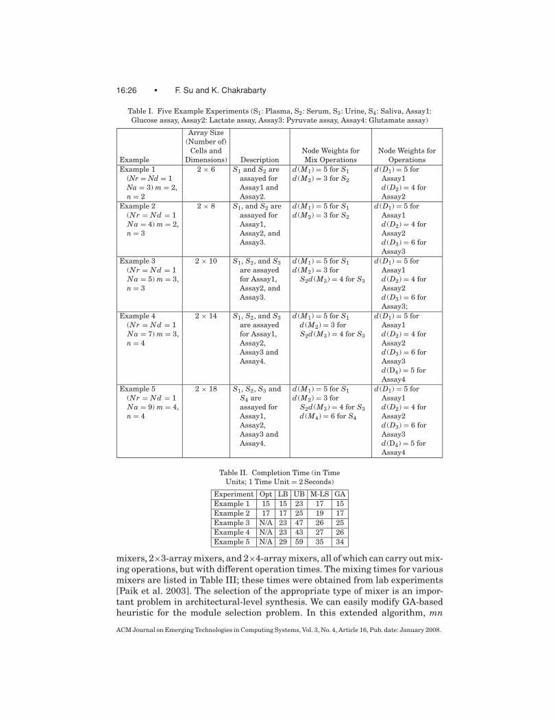
corresponding to Example 1 and Example 2, the optimal solutions have beenobtained using the ILP model. (For the other three problem instances, the ILPmodel did not yield a solution within reasonable time, i.e., within 5 hours.) Up-per bounds and lower bounds are also listed in the Table II. These experimentswere performed on a server with two AMD Opteron 250 processors runningat 2.4GHz with a 1MB L2 Cache, and 4GB of RAM. The GA procedure took497 seconds of CPU time for Example 5. The CPU time was negligible for thesmaller examples.
The results show that both M-LS and GA are able to generate good solutions,which are very close to the lower bounds. The ratio of the completion timeobtained using the heuristic methods to the lower bound is no more than 1.2in most cases, as shown in Figure 23. While GA yields lower completion timesthan M-LS, it requires O(Gn2) complexity compared to the O(n) complexity forM-LS, where n is the number of operations and G is the number of generationsused in the genetic algorithm.
5.2 Resource Selection
We next show that we can easily address the problem of resource selection us-ing the heuristic based on the genetic algorithm. The modified list schedulingalgorithm cannot be directly used to solve this problem. As indicated in Section4, there exist several types of reconfigurable resources, for example, 2×2-array
ACM Journal on Emerging Technologies in Computing Systems, Vol. 3, No. 4, Article 16, Pub. date: January 2008.
16:26 • F. Su and K. Chakrabarty
Table I. Five Example Experiments (S1: Plasma, S2: Serum, S3: Urine, S4: Saliva, Assay1:Glucose assay, Assay2: Lactate assay, Assay3: Pyruvate assay, Assay4: Glutamate assay)
Array Size(Number of)
Cells and Node Weights for Node Weights forExample Dimensions) Description Mix Operations OperationsExample 1
(Nr = Nd = 1Na = 3) m = 2,n = 2
2 × 6 S1 and S2 areassayed forAssay1 andAssay2.
d (M1) = 5 for S1d (M2) = 3 for S2
d (D1) = 5 forAssay1d (D2) = 4 forAssay2
Example 2(Nr = Nd = 1Na = 4) m = 2,n = 3
2 × 8 S1, and S2 areassayed forAssay1,Assay2, andAssay3.
d (M1) = 5 for S1d (M2) = 3 for S2
d (D1) = 5 forAssay1d (D2) = 4 forAssay2d (D3) = 6 forAssay3
Example 3(Nr = Nd = 1Na = 5) m = 3,n = 3
2 × 10 S1, S2, and S3are assayedfor Assay1,Assay2, andAssay3.
d (M1) = 5 for S1d (M2) = 3 for
S2d (M3) = 4 for S3
d (D1) = 5 forAssay1d (D2) = 4 forAssay2d (D3) = 6 forAssay3;
Example 4(Nr = Nd = 1Na = 7) m = 3,n = 4
2 × 14 S1, S2, and S3are assayedfor Assay1,Assay2,Assay3 andAssay4.
d (M1) = 5 for S1d (M2) = 3 forS2d (M3) = 4 for S3
d (D1) = 5 forAssay1d (D2) = 4 forAssay2d (D3) = 6 forAssay3d (D4) = 5 forAssay4
Example 5(Nr = Nd = 1Na = 9) m = 4,n = 4
2 × 18 S1, S2, S3 andS4 areassayed forAssay1,Assay2,Assay3 andAssay4.
d (M1) = 5 for S1d (M2) = 3 for
S2d (M3) = 4 for S3d (M4) = 6 for S4
d (D1) = 5 forAssay1d (D2) = 4 forAssay2d (D3) = 6 forAssay3d (D4) = 5 forAssay4
Table II. Completion Time (in TimeUnits; 1 Time Unit = 2 Seconds)
Experiment Opt LB UB M-LS GAExample 1 15 15 23 17 15Example 2 17 17 25 19 17Example 3 N/A 23 47 26 25Example 4 N/A 23 43 27 26Example 5 N/A 29 59 35 34
mixers, 2×3-array mixers, and 2×4-array mixers, all of which can carry out mix-ing operations, but with different operation times. The mixing times for variousmixers are listed in Table III; these times were obtained from lab experiments[Paik et al. 2003]. The selection of the appropriate type of mixer is an impor-tant problem in architectural-level synthesis. We can easily modify GA-basedheuristic for the module selection problem. In this extended algorithm, mn
ACM Journal on Emerging Technologies in Computing Systems, Vol. 3, No. 4, Article 16, Pub. date: January 2008.

High-Level Synthesis of Digital Microfluidic Biochips • 16:27
Table III. Mixing Times for Various Types of Mixers (in Time Units; 1 Time Unit = 2 Seconds)
Mixing Time for Mixing Time for Mixing Time for Mixing Time forMixer Type Plasma Samples Serum Samples Urine Samples Saliva Samples2×2-array mixer 7 5 6 82×3-array mixer 6 4 5 72×4-array mixer 5 3 4 6
Fig. 24. Completion time for a set of multiplexed bioassays.
additional genes are added to the chromosome to denote the module selec-tion information, that is, Chromosome = {gene(1), . . . , gene(k), . . . , gene(2k),gene(2k + 1), . . . , gene(2k + mn)}. During the ad-hoc schedule construction pro-cedure, a mixer module is selected for the mixing operation v2mn+i based on thecorresponding gene(2k + i), i = 1, . ., mn. For example, a 2×4-array mixer isselected if gene(2k + i) < 0.33; a 2×3-array mixer is selected, if gene(2k + i) >
0.67; otherwise a 2×2-array mixer is selected.Figure 24 shows the simulation results obtained from the GA-based heuris-
tic algorithm. Note that module selection leads to a better solution, since aneffective tradeoff between resource area and operation time can be obtainedthrough careful resource selection.
5.3 Application to Protein Assay
Finally we evaluate the proposed GA-based heuristic method by using it todesign a microfluidic array for a larger application, that is, a dilution-basedprotein assay. As in colorimetric glucose assays, the protocol for a protein as-say based on the Bradford reaction [Srinivasan et al. 2004] also belongs to thegeneric class of droplet-based bioassay operations Passay discussed in Section4.1. Compared to the previous examples, there is a new type of operation, thatis, dilution, that is used in a protein assay. Buffer droplets, such as 1M NaOHsolution, are used to dilute the sample containing protein(s) to obtain a desireddilution factor (DF), before mixing with reagents droplets (e.g., Coomassie bril-liant blue G-250 dye). This on-chip dilution is performed using multiple hierar-chies of binary mixing/splitting phases, referred to as the interpolating serialdilution method [Fair et al. 2003]. The mixing of a sample droplet of protein
ACM Journal on Emerging Technologies in Computing Systems, Vol. 3, No. 4, Article 16, Pub. date: January 2008.

16:28 • F. Su and K. Chakrabarty
Fig. 25. Sequencing graph model of a protein assay.
concentration C and a unit buffer droplet results in a droplet with twice theunit volume, and concentration C/2. Splitting this large droplet results in twounit-volume droplets of concentration C/2 each. Continuing this step in a recur-sive manner using diluted droplets as samples, an exponential dilution factorof DF = 2N can be obtained in N steps.
A sequencing graph model can be developed from the protocol for a proteinassay (DF = 128), as shown in Figure 25. There are a total of 103 nodes inone-to-one correspondence with the set of operations in a protein assay, whereDsS, DsBi (i = 1, . . . , 39), and DsRi (i = 1, . . . , 8) represents the generation anddispensing of sample, buffer and reagent droplets, respectively. In addition, Dlti(i = 1, . . . , 39) denotes the binary dilution (including mixing/splitting) opera-tions, Mixi(i = 1, . . . , 8) represents the mixing of diluted sample droplets, andreagent droplets; Opti(i = 1, . . . , 8) denotes the optical detection of the mixeddroplets. Until the fourth step of a serial dilution, all diluted sample dropletsare retained in the microfluidic array. After that stage, for each binary dilutionstep, only one diluted sample droplet is retained after splitting, while the otherdroplet is moved to the waste reservoir. The basic operations for protein as-say have been implemented on a digital microfluidic biochip [Srinivasan et al.2004-2] [Fair et al. 2003].
Table IV lists the available functional resources for the protein assay. Weassume that there is only one on-chip reservoirs/dispensing port available forsample fluids, but two such ports for buffer fluids, two for reagent fluids, and onefor waste fluids. We also assume that four optical detectors can be integratedinto a 10×10 microfluidic array.
ACM Journal on Emerging Technologies in Computing Systems, Vol. 3, No. 4, Article 16, Pub. date: January 2008.
High-Level Synthesis of Digital Microfluidic Biochips • 16:29
Table IV. Functional Resources for Synthesis
Operation Resources Time (s)Dispensing: DsS; DsB; DsR On-chip reservoir/dispensing port 7Dilution: Dlt 2×4-array dilutor 5Mixing: Mix 2×4-array mixer 3Optical detection: Opt LED+Photodiode 30Storage Single cell N/A
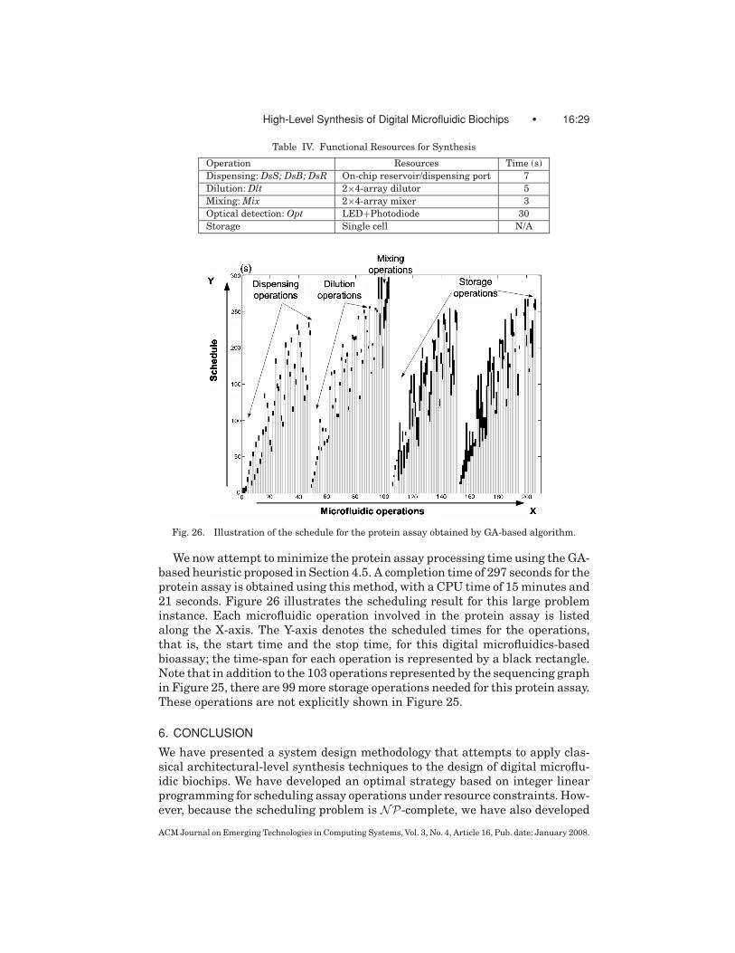
Fig. 26. Illustration of the schedule for the protein assay obtained by GA-based algorithm.
We now attempt to minimize the protein assay processing time using the GA-based heuristic proposed in Section 4.5. A completion time of 297 seconds for theprotein assay is obtained using this method, with a CPU time of 15 minutes and21 seconds. Figure 26 illustrates the scheduling result for this large probleminstance. Each microfluidic operation involved in the protein assay is listedalong the X-axis. The Y-axis denotes the scheduled times for the operations,that is, the start time and the stop time, for this digital microfluidics-basedbioassay; the time-span for each operation is represented by a black rectangle.Note that in addition to the 103 operations represented by the sequencing graphin Figure 25, there are 99 more storage operations needed for this protein assay.These operations are not explicitly shown in Figure 25.
6. CONCLUSION
We have presented a system design methodology that attempts to apply clas-sical architectural-level synthesis techniques to the design of digital microflu-idic biochips. We have developed an optimal strategy based on integer linearprogramming for scheduling assay operations under resource constraints. How-ever, because the scheduling problem is NP-complete, we have also developed
ACM Journal on Emerging Technologies in Computing Systems, Vol. 3, No. 4, Article 16, Pub. date: January 2008.

16:30 • F. Su and K. Chakrabarty
two heuristic techniques that scale well for large problem instances. Two real-life biochemical assays, namely multiplexed in-vitro diagnostics and proteinassays, have been used to evaluate the proposed methodology.
While the heuristic based on list scheduling is computationally more effi-cient, the second heuristic based on a genetic algorithm yields lower completiontimes for bioassays. The two methods appear to provide a trade-off betweenthe quality of the results (assay completion time) and the CPU time. Whilethe CPU time for the GA-based algorithm is reasonable for the larger proteinassay, computation might be an issue for future applications, for example, pro-tocols that require decisions based on the feedback from intermediate assayresults.
The proposed synthesis approach is expected to reduce human effort anddesign cycle time, and it will facilitate the integration of fluidic components withmicroelectronic components in next-generation SOCs. Research on CAD toolsfor microfluidics system design is still in its infancy. Nevertheless, microfluidicbiochips promise to emerge as a major application driver for continued researchon synthesis techniques.
ACKNOWLEDGMENTS
We thank Tao Xu of Duke University for helping with the simulations.
REFERENCES
AARTS, E. AND KORST, J. 1989. Simulated Annealing and Boltzmann Machines. John Wiley.ADVANCED LIQUID LOGIC, INC. www.liquid-logic.com.ANTAO, B. AND BRODERSEN, A. 1992. Techniques for synthesis of analog integrated circuits. IEEE
Des. Test Comput. 9, 8–18.BEAN, J. C. 1994. Genetics and random keys for sequencing and optimization. ORSA J. Comput.
6, 154–160.BERKELAAR, M. lpsolve. Eindhoven University of Technology, Eindhoven, Netherlands.
ftp://ftp.ics.ele.tue.nl/pub/lp solve.BOHRINGER, K. F. 2004. Towards optimal strategies for moving droplets in digital microfluidic
systems. In Proceedings of the IEEE International Conference on Robotics and Automation. 1468–1474.
BURNS, M. A., JOHNSON, B. N., BRAHMASANDRA, S. N., AND HANDIQUE, K. 1998. An integrated nano-liter DNA analysis device. Science 282, 484–487.
CAMPOSANO, R. 1996. Behavioral synthesis. In Proceedings of the IEEE/ACM Design AutomationConference, 33–34.
CHO, S. K., FAN, S. K., MOON, H., AND KIM, C. J. 2002. Toward digital microfluidic circuits: Cre-ating, transporting, cutting and merging liquid droplets by electrowetting-based actuation. InProceedings of the IEEE Conference on Micro-Electro-Mechanical Systems. 32–52.
COVENTORWARE. Micro-electro-mechanical systems. http://www.coventor.com.DE, S. K. AND ALURU, N. R. 2003. Physical and reduced-order dynamic analysis of MEMS.
In Proceedings of the IEEE/ACM International Conference on Computer-Aided Design. 270–273.
DING, J., CHAKRABARTY, K., AND FAIR, R. B. 2001. Scheduling of microfluidic operations for reconfig-urable two-dimensional electrowetting arrays. IEEE Trans. Comput.-Aid. Des. Integr. Circ. Sys.20, 1463–1468.
FAIR, R. B., KHLYSTOV, A., TAYLOR, T. D., IVANOV, V., KVANS, R. D., SRINIVASAN, A., PAMOLA, V. K., POL-LOCK, M. G., GRIFFIN, P. B., AND ZHOU, J. 2006. Chemical and biological applications of digitalmicrofluidic devices. IEEE Des. Test Comput. 24, 10–24.
ACM Journal on Emerging Technologies in Computing Systems, Vol. 3, No. 4, Article 16, Pub. date: January 2008.

High-Level Synthesis of Digital Microfluidic Biochips • 16:31
FAIR, R. B., KHLYSTOV, A., SRINIVASAN, V., PAMULA, V. K., AND WEAVER, K. N. 2004. Integratedchemical/biochemical sample collection, pre-concentration, and analysis on a digital microfluidiclab-on-a-chip platform. In Proceedings of the SPIE Lab-on-a-Chip: Platforms, Devices, and Ap-plications. L. A. Smith and D. Sobek, Eds. 5591, 113–124.
FAIR, R. B., SRINIVASAN, V., PAIK, P., REN, H., AND PAMULA, V. K. 2003. Electrowetting-based on-chip sample processing for integrated microfluidics. In Proceedings of the IEEE InternationalElectronic Devices Meeting (IEDM). 32.5.1–32.5.4.
FEDDER, G. K. AND Q. JING, Q. 1999. A hierarchical circuit-level design methodology for micro-electromechinal system. IEEE Trans. Circ. Syst. II. 46, 1309–1315.
GALLARDO, B. S., GUPTA, V. K., EAGERTON, F. D., JONG, L. I., CRAIG, V. S., SHAH, R. R., AND ABBOTT, N. L.1999. Electrochemical principles for active control of liquids on submillimeter scales. Science283, 57–60.
GAREY, M. R. AND JOHNSON, D. S. 1979. Computers and Intractability—A Guide to the Theory ofNP-Completeness. Freeman, New York, NY.
GRIFFITH, E. AND AKELLA, S. 2004. Coordinating multiple droplets in planar array digital microflu-idics systems. In Proceedings of the Workshop on the Algorithmic Foundations of Robotics.
HULL, H. F., DANILA, R., AND EHRESMANN, K. 2003. Smallpox and bioterrorism: Public-health re-sponses. J. Lab. Clin. Medicine 142, 221–228.
ICHIMURA, K., OH, S., AND NAKAGAWA, M. 2000. Light-driven motion of liquids on a photoresponsivesurface. Science 288, 1624–1626.
INTERNATIONAL TECHNOLOGY ROADMAP FOR SEMICONDUCTORS (ITRS). http://public.itrs.net/Files/2003ITRS/Home2003.htm.
JONES, T. B., GUNJI, M., WASHIZU, M., AND FELDMAN, M. J. 2001. Dielectrophoretic liquid actuationand nanodroplet formation. J. Appl. Phys. 89, 1441–1448.
KAHNG, B., MANDOIU, I. I., REDA, S., XU, X., AND ZELIKOVSKY, A. 2003. Evaluation of placement tech-niques for DNA probe array layout. In Proceedings of the IEEE/ACM International Conferenceon Computer-Aided Design. 262–269.
KWOK, Y. AND AHMAD, I. 1999. Static scheduling algorithms for allocating directed task graphs tomultiprocessors. ACM Comput. Surv. 31, 406–471.
MICHELI, G. DE. 1994. Synthesis and Optimization of Digital Circuits. McGraw-Hill, New York,NY.
MUKHERJEE, T. AND FEDDER, G. K. 1998. Design methodology for mixed-domain systems-on-a-chip[MEMS design]. In Proceedings of the IEEE Conference on VLSI System Level Design. 96–101.
PAIK, P., PAMULA, V. K., AND FAIR, R. B. 2003. Rapid droplet mixers for digital microfluidic systems.Lab on a Chip 3, 253–259.
PAMULA, K., SRINIVASAN, V., CHAKRAPANI, H., FAIR, R. B., AND TOONE, E. J. 2005. A droplet-basedlab-on-a-chip for colorimetric detection of nitroaromatic explosives. In Proceedings of the IEEEConference on Micro-Electro-Mechanical Systems. 722–725.
PFEIFFER, J., MUKHERJEE, T., AND HAUAN, S. 2004. Simultaneous design and placement of multi-plexed chemical processing systems on microchip. In Proceedings of the IEEE/ACM InternationalConference on Computer-Aided Design. 229–236.
POLLACK, M. G. 2001. Electrowetting-based microactuation of droplets for digital microfluidics.Ph.D. thesis, Duke University.
POLLACK, M. G., FAIR, R. B., AND SHENDEROV, A. D. 2000. Electrowetting-based actuation of liquiddroplets for microfluidic applications. Appl. Phys. Lett. 77, 1725–1726.
POLLACK, M. G., SHENDEROV, A. D., AND FAIR, R. B. 2002. Electrowetting-based actuation of dropletsfor integrated microfluidics. Lab on a Chip 2, 96–101.
REN, H. AND FAIR, R. B. 2002. Micro/nano liter droplet formation and dispensing by capacitancemetering and electrowetting actuation. Technical Digest of IEEE-NANO, 36–38.
RICKETTS, J. IRICK, K. VIJAYKRISHNAN, N. AND IRWIN, M. J. 2006. Priority scheduling in digitalmicrofluidics-based biochips. In Proceedings of the Conference on Design, Automation and Testin Europe. 329–334.
SAMMARCO, T. S. AND BURNS, M. A. 1999. Thermocapillary pumping of discrete droplets in micro-fabricated analysis devices. Amer. Inst. Chem. Engin. J. 45, 350–366.
SCHULTE, T. H., BARDELL, R. L., AND WEIGL, B. H. 2002. Microfluidic technologies in clinical diag-nostics. Clinica Chimica Acta 321, 1–10.
ACM Journal on Emerging Technologies in Computing Systems, Vol. 3, No. 4, Article 16, Pub. date: January 2008.

16:32 • F. Su and K. Chakrabarty
SENTURIA, S. 1987. Microfabricated structures for the measurement of mechanical properties andadhesion of thin films. In Proceedings of the International Conference on Sold-State Sensors andActuators (Transducers). 11–16.
SHAPIRO, H., MOON, H., GARRELL, R., AND KIM, C. J. 2003. Modeling of electrowetted surface tensionfor addressable microfluidic systems: dominant physical effects, material dependences, and lim-iting phenomena. In Proceedings of the IEEE Conference on Micro-Electro-Mechanical Systems.201–205.
SILICON BIOSYSTEMS. What is DEPArrayTM? http://www.siliconbiosystems.com/technology/DEPArray.htm.
SPEARS, W. M. AND DEJONG, K. A. 1991. On the virtues of parameterized uniform crossover. InProceedings of the International Conference on Genetic Algorithms. 230–236.
SRINIVAS, M. AND PATNAIK, L. M. 1994. Genetic algorithms: a survey. IEEE Comput. 27, 17–26.SRINIVASAN, V., PAMULA, V. K., AND FAIR, R. B. 2004. An integrated digital microfluidic lab-on-a-chip
for clinical diagnostics on human physiological fluids. Lab on a Chip, 310–315.SRINIVASAN, V., PAMULA, V. K., PAIK, P., AND FAIR, R. B. 2004. Protein stamping for MALDI mass
spectrometry using an electrowetting-based microfluidic platform. In Proceedings of the SPIE.5591, 26–32.
SRINIVASAN, V., PAMULA, V. K., POLLACK, M. G., AND FAIR, R. B. 2003. Clinical diagnostics on humanwhole blood, plasma, serum, urine, saliva, sweat, and tears on a digital microfluidic platform. InProceedings of the International Conference on Micro Total Analysis Systems. 1287–1290.
SU, F. AND CHAKRABARTY, K. 2006. Module placement for fault-tolerant microfluidics-basedbiochips. ACM Trans. Des. Automat. Elect. Syst. 11, 682–710.
SU, F., CHAKRABARTY, K., AND FAIR, R. B. 2006. Microfluidics-based biochips: technology issues,implementation platforms, and design automation challenges. IEEE Trans. Comput.-Aid. Des.Integr. Circ. Syst. 25, 211–223.
SU, F., HWANG, W. AND CHAKRABARTY, K. 2006. Droplet routing in the synthesis of digital microflu-idic biochips. In Proceedings of the Design, Automation and Test in Europe (DATE) Conference.323–328.
SU, F., OZEV, S., AND CHAKRABARTY, K. 2004. Concurrent testing of droplet-based microfluidic sys-tems for multiplexed biomedical assays. In Proceedings of the IEEE International Test Conference.883–892.
SU, F., OZEV, S., AND CHAKRABARTY, K. 2005. Ensuring the operational health of droplet-basedmicroelectrofluidic biosensor systems. IEEE Sensors 5, 763–773.
THORSEN, T., MAERKL, S., AND QUAKE, S. 2002. Microfluidic large-scale integration. Science 298,580–584.
VAN DER WOERD, M., FERREE, D., AND PUSEY, M. 2003. The promise of macromolecular crystallizationin microfluidic chips. J. Struct. Biol. 142, 180–187.
VENKATESH, S. AND MEMISH, Z. A. 2003. Bioterrorism: A new challenge for public health. Int. J.Antimicrobial Agents 21, 200–206.
VERPOORTE, E. AND DE ROOIJ, N. F. 2003. Microfluidics meets MEMS. In Proceedings of the IEEE.91, 930-953.
WALKER, R. A. AND CAMPOSANO, R. 1991. A Survey of High-Level Synthesis Systems. Kluwer Aca-demic Publishers, Boston, MA.
WASHIZU, M. 1998. Electrostatic actuation of liquid droplets for microreactor applications. IEEETrans. Indus. Appl. 34, 732–737.
ZENG, J. AND KORSMEYER, F. T. 2004. Principles of droplet electrohydrodynamics for lab-on-a-chip.Lab on a Chip 4, 265–277.
ZHANG, T., CHAKRABARTY, K., AND FAIR, R. B. 2002. Microelectrofluidic Systems: Modeling and Sim-ulation. CRC Press, Boca Raton, FL.
ZHAO, Y. AND CHO, S. K. 2006. Microparticle sampling by electrowetting-actuated droplet sweep-ing. Lab on a Chip 6, 137–144.
Received February 2007; revised April 2007; accepted May 2007
ACM Journal on Emerging Technologies in Computing Systems, Vol. 3, No. 4, Article 16, Pub. date: January 2008.