High-Level Programming Languages for Bio-molecular...
34
Chapter 1 HIGH-LEVEL PROGRAMMING LANGUAGES FOR BIO-MOLECULAR SYSTEMS Jacob Beal BBN Technologies Cambridge, Massachusetts [email protected] Andrew Phillips Microsoft Research Cambridge, England [email protected] Douglas Densmore Boston University Boston, Massachusetts [email protected] Yizhi Cai Johns Hopkins University Baltimore, Maryland [email protected] Abstract In electronic computing, high-level languages hide much of the details, allowing non-experts and sometimes even children to program and cre- ate systems. High level languages for bio-molecular systems aim to achieve a similar level of abstraction, so that a system might be de- signed on the basis of the behaviors that are desired, rather than the particulars of the genetic code that will be used to implement these behaviors. The drawback to this sort of high-level approach is that it generally means giving up control over some aspects of the system and having decreased efficiency relative to hand-tuned designs. Different
Transcript of High-Level Programming Languages for Bio-molecular...

Chapter 1
HIGH-LEVEL PROGRAMMING LANGUAGESFOR BIO-MOLECULAR SYSTEMS
Jacob BealBBN TechnologiesCambridge, Massachusetts
Andrew PhillipsMicrosoft ResearchCambridge, England
Douglas DensmoreBoston UniversityBoston, Massachusetts
Yizhi CaiJohns Hopkins UniversityBaltimore, Maryland
Abstract In electronic computing, high-level languages hide much of the details,allowing non-experts and sometimes even children to program and cre-ate systems. High level languages for bio-molecular systems aim toachieve a similar level of abstraction, so that a system might be de-signed on the basis of the behaviors that are desired, rather than theparticulars of the genetic code that will be used to implement thesebehaviors. The drawback to this sort of high-level approach is that itgenerally means giving up control over some aspects of the system andhaving decreased efficiency relative to hand-tuned designs. Different
2
languages make different tradeoffs in which aspects of design they em-phasize and which they automate, so we expect that for biology, therewill be no single “right language,” just as there is not for electronic com-puting. Because synthetic biology is a new area, no mature languageshave yet emerged. In this chapter, we present an in-depth survey of fourrepresentative languages currently in development—GenoCAD, Eugene,GEC, and Proto—as well as a brief overview of other related high-leveldesign tools.
Keywords: Synthetic biology, abstraction, high level languages, GenoCAD, GEC,Proto, Eugene, modeling, design, XOR
1. Overview
A “high-level” programming language is one that abstracts many ofthe details of how a computation will actually be implemented. Theprogrammer writes down a simple description, capturing the essence ofthe computation, and this description is automatically expanded to pro-duce a complete implementation that can be executed on the availablecomputational substrate.
On modern digital computers, this process can go through many dif-ferent layers. Consider, for example, an entry in a Microsoft Excelspreadsheet that adds up a column of figures. The expression itself,something like “= SUM(C1:C10)”, is a transparently simple state-ment in an arithmetic-centric high-level language. Within Excel, thisstatement is interpreted into a set of calls to various functions within Ex-cel, in the process adding implicit behaviors like error handling. TheseExcel functions were themselves written in some high-level language,and then compiled into machine code that can execute on the computerwhere Excel is running, in the process making routine decisions likehow to implement each mathematical operation using the resources ofthe machine’s processor. Even that machine code goes through anotherlayer of interpretation, as the processor itself restructures the code tooperate more efficiently given the current state of the processor.
The essence of the idea behind high-level languages is this: as an en-gineering field matures, finding good-enough solutions to sub-problemsof design becomes routine. Highly routine problem solving can thenbe automated, reifying the knowledge of skilled engineers into a pieceof software. The software solutions to individual parts of the designprocess can then be connected together to form a complete tool-chain,translating from high-level descriptions down to working implementa-tions without any need for human intervention.

Languages for Bio-Molecular Systems 3
Separating the programmer from the implementation details has threeimportant benefits:
Accessibility: less knowledge is required to build a system, sincemuch of the required knowledge has been captured in software.
Scalability: since routine design work is automated, it is possibleto build larger and more complex systems, and to re-use the sameprograms on different platforms.
Reliability: aspects of design that are automated are no longersubject to programmer error; software can also check for commonerrors in the programmer’s high-level design.
On electronic computers, high-level languages have become so suc-cessful that few people ever use anything besides a high-level language.In the programming of bio-molecular systems, high-level languages arejust beginning to emerge.
For the purposes of this chapter, we will define a high-level languagefor bio-molecular systems as any system description language where thechoice of implementing biological parts may routinely be left unspeci-fied. We will focus primarily on programming languages for in vivo bio-molecular computation, reviewing four representative languages: Geno-CAD, Eugene, GEC, and Proto in rough order from lower to higherlevels of abstraction. To aid comparison and understanding, we applyeach language to a simple example problem:
Express green fluorescent protein (GFP) when either of the small-moleculesignals aTc or IPTG is present, but not when both are present.
At the end of the chapter, we also review the scope of other relatedhigh-level design tools for bio-molecular computing systems.
2. GenoCAD
GenoCAD (www.genocad.org) is one of the earliest CAD tools forsynthetic biology, built upon the foundation of formal grammars. In thissection, we summarize the basics of grammars, the theoretical foundationunderneath GenoCAD and also a brief tutorial on how programs areconstructed using the GenoCAD web service.
Formal Language & Syntactic Model
A formal language is a set of (possibly infinite) strings derived froman alphabet Σ, which encodes information for communication purposes.There are several kinds of languages, including natural languages (e.g.,
4
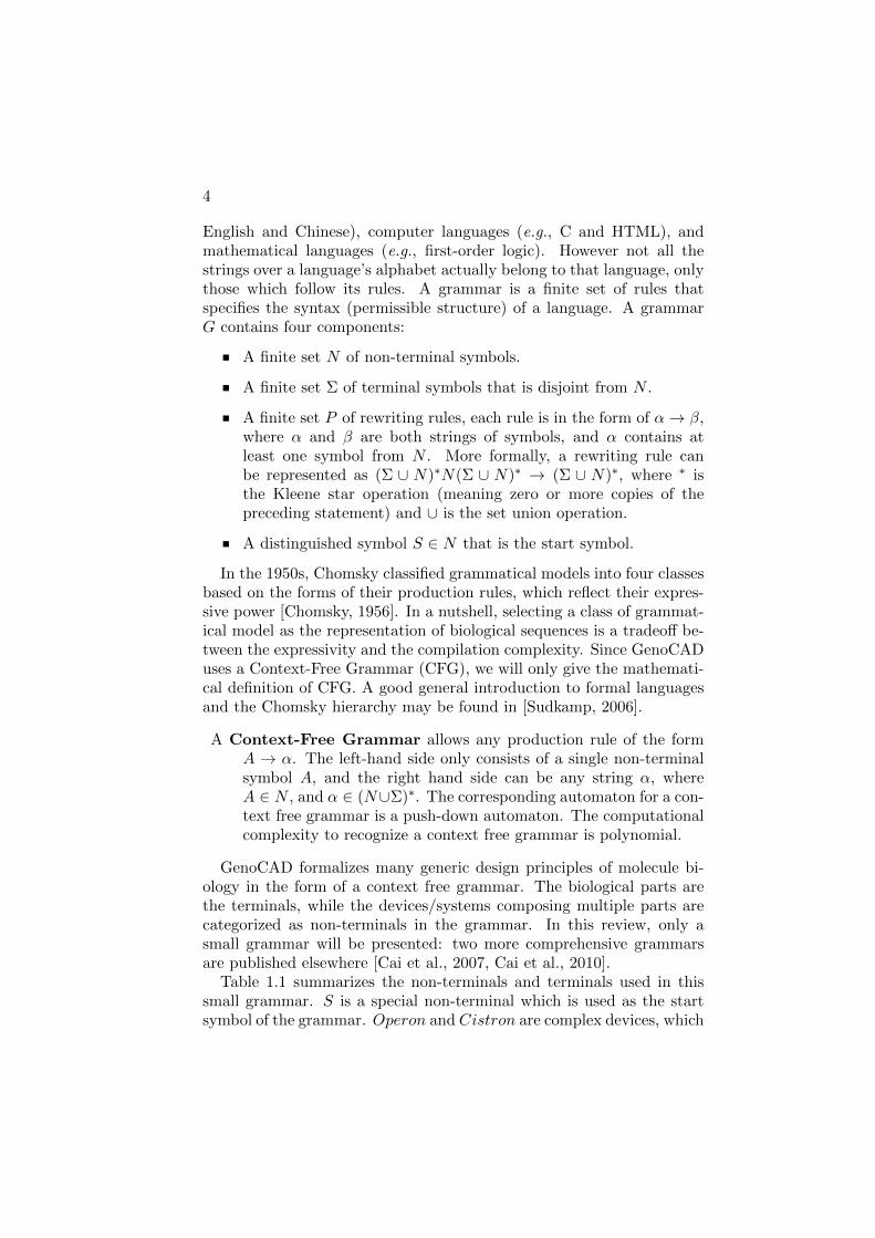
English and Chinese), computer languages (e.g., C and HTML), andmathematical languages (e.g., first-order logic). However not all thestrings over a language’s alphabet actually belong to that language, onlythose which follow its rules. A grammar is a finite set of rules thatspecifies the syntax (permissible structure) of a language. A grammarG contains four components:
A finite set N of non-terminal symbols.
A finite set Σ of terminal symbols that is disjoint from N .
A finite set P of rewriting rules, each rule is in the form of α→ β,where α and β are both strings of symbols, and α contains atleast one symbol from N . More formally, a rewriting rule canbe represented as (Σ ∪ N)∗N(Σ ∪ N)∗ → (Σ ∪ N)∗, where ∗ isthe Kleene star operation (meaning zero or more copies of thepreceding statement) and ∪ is the set union operation.
A distinguished symbol S ∈ N that is the start symbol.
In the 1950s, Chomsky classified grammatical models into four classesbased on the forms of their production rules, which reflect their expres-sive power [Chomsky, 1956]. In a nutshell, selecting a class of grammat-ical model as the representation of biological sequences is a tradeoff be-tween the expressivity and the compilation complexity. Since GenoCADuses a Context-Free Grammar (CFG), we will only give the mathemati-cal definition of CFG. A good general introduction to formal languagesand the Chomsky hierarchy may be found in [Sudkamp, 2006].
A Context-Free Grammar allows any production rule of the formA → α. The left-hand side only consists of a single non-terminalsymbol A, and the right hand side can be any string α, whereA ∈ N , and α ∈ (N∪Σ)∗. The corresponding automaton for a con-text free grammar is a push-down automaton. The computationalcomplexity to recognize a context free grammar is polynomial.
GenoCAD formalizes many generic design principles of molecule bi-ology in the form of a context free grammar. The biological parts arethe terminals, while the devices/systems composing multiple parts arecategorized as non-terminals in the grammar. In this review, only asmall grammar will be presented: two more comprehensive grammarsare published elsewhere [Cai et al., 2007, Cai et al., 2010].
Table 1.1 summarizes the non-terminals and terminals used in thissmall grammar. S is a special non-terminal which is used as the startsymbol of the grammar. Operon and Cistron are complex devices, which

Languages for Bio-Molecular Systems 5
Table 1.1. GenoCAD small grammar set of terminal and non-terminal symbols.
Non-terminals TerminalsS -Operon -Cistron -Promoter prom1, prom2, prom3RBS rbs1, rbs2, rbs3Gene lacI, tetR, gfpTerminator b0012, b0015
Table 1.2. GenoCAD small context free grammar of gene expression.
Number RuleP1 S → OperonP2 Operon→ Operon,OperonP3 Operon→ Promoter, Cistron, TerminatorP4 Cistron→ RBS,GeneP5 Cistron→ Cistron,CistronP6 Terminator → Terminator, TerminatorP7 · · ·P9 Promoter → prom1|prom2|prom3P10 · · ·P12 RBS → rbs1|rbs2|rbs3P13 · · ·P15 Gene→ lacI|tetR|gfpP16, P17 Terminator → b0012|b0015
are composed of multiple basic parts (terminals). In the category ofPromoter, there are three terminals, namely prom1, prom2 and prom3.Similarly, a ribosome binding site RBS can be chosen from rbs1, rbs2and rbs3, while a Gene could be lacI or tetR or gfp. Finally, there aretwo terminals b0012 and b0015 belong to the non-terminal Terminator.Table 1.2 presents a context free grammar for designing gene expressioncassettes. The whole grammar can be divided into two sections: rulesP1 – P6 transform the structure of a design, while rules P7 – P17 areused to select a particular terminal for each non-terminal category. Thedesign starts with P1, where the start symbol S becomes an expressionOperon. Multiple Operons are allowed by applying rule P2 multipletimes: for a design with n cassettes, P2 is applies n − 1 times. RuleP3 specifies the structure of an Operon to be a Promoter, followedby a Cistron and a Terminator. A Cistron can be broken down by

6
rule P4 as an RBS and a Gene. Multiple Cistrons and Terminatorsare allowed in a design by rules P5 and P6, respectively. After thestructure of a design is defined, rules P7 – P17 are used to transformeach non-terminal to a specific biological part (terminal). For instance,rules P7, P8 and P9 specify prom1, prom2 and prom3 respectively toreplace non-terminal Promoter (the ‘|’ sign indicates OR relationship).
Figure 1.1. Grammatical design of a DNA sequence. Panel 1: a parsing tree showingthe step-by-step application of rules to generate the sequence (excepting terminalselection). Each step is labeled with the rule applied. Panel 2: Representation of thegenerated DNA part sequence, using a standard set of synthetic biology icons. Panel3: The designed DNA sequence.
Figure 1.1 shows how this simple syntactic model can be applied togenerate a sequence structurally consistent with the XOR gates devel-oped below in our presentation of Eugene (Figure 1.3) and GEC (Fig-ure 1.4). The design process starts with applying P1 to the start symbolS to transform the design into a single Operon. After applying P3 twice,the design becomes three Operons. In the next step, rule P3 defines thestructure of each Operon as a Promoter, a Cistron and a Terminator.In order to express lacI and tetR under control of the same constitutivepromoter, P5 is applied to allow two Cistrons in the leftmost Operon.Finally, rule P4 breaks down each Cistron into an RBS followed by a

Languages for Bio-Molecular Systems 7
Gene. Once the structure of the design is decided, a part is selected foreach category (Figure 1.1.2) and mapped to a DNA sequence that canbe exported for synthesis (Figure 1.1.3).
If we operate the process in Figure 1.1 in reverse, then rather thangenerating a DNA sequence, we can validate whether a specified DNAsequence is consistent with the syntactic model. This is carried out withan automated process known as “parsing” in computer science. Theparser operates in the reverse order of the design process: the Geno-CAD parser takes the DNA sequence (panel 3 in Figure 1.1) as inputand breaks it into a series of biological parts (panel 2 in Figure 1.1). Itthen checks for the existence of at least one rule application tree thatcan generate this series of parts using the context-free grammar. Real-izing that we can build parsers from the syntactic model opens up thepossibility of viewing DNA sequences as a programming language. Onecan make changes to a DNA sequence just like writing source code, anduse the parser to check whether the new DNA sequence is still consistentwith the syntactic model (which formalizes the biological knowledge).
It should be noted that the syntactic model only checks the structure,but not the meaning of the design. A syntactically correct sentence is notnecessarily meaningful. In the context of synthetic biology, this meansthe syntactic model only controls the order of putting biological partstogether to ensure a successful gene expression, but the function of theDNA sequence (i.e., what does this sequence do?) remains unknown.Recently, GenoCAD has been extended to address this area with theintroduction of an attribute grammar to develop semantic models ofDNA sequences [Cai et al., 2009]. By associating biological attributeswith parts, and coupling semantic actions with each production rule, thesemantic models are capable of translating a class of DNA sequences tomathematical models that describe the encoded phenotypic behavior.
GenoCAD Web Service
Based on the syntactic model originally described in [Cai et al., 2007],an open-source web application (www.genocad.org) has been imple-mented. GenoCAD constrains the design space using the underlyingsyntactic models, and guides the user through the design process ina “point and click” fashion. This has been extended recently with asecond syntactic model, designed specifically for BioBrickTM-based con-structs [Cai et al., 2010].
The GenoCAD web tool applies these syntactic models to supportboth design and validation of sequences [Czar et al., 2009] (though at themoment when this chapter was written, the validation section was offline
8
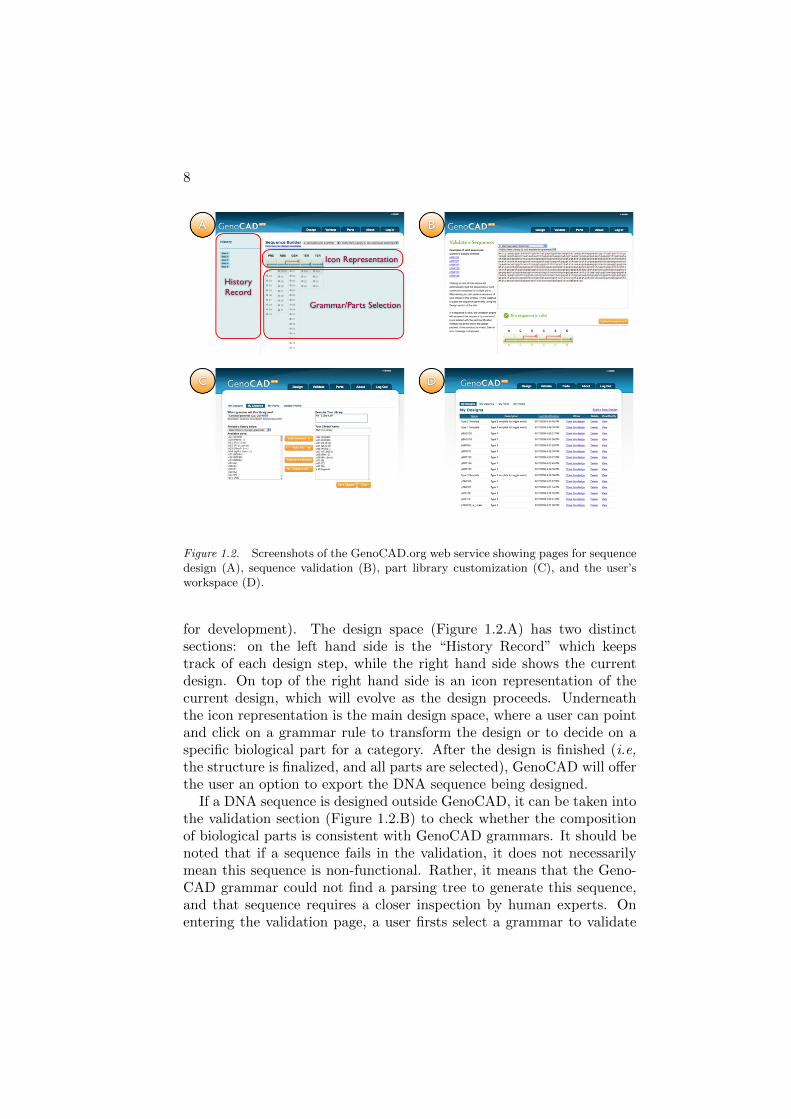
Figure 1.2. Screenshots of the GenoCAD.org web service showing pages for sequencedesign (A), sequence validation (B), part library customization (C), and the user’sworkspace (D).
for development). The design space (Figure 1.2.A) has two distinctsections: on the left hand side is the “History Record” which keepstrack of each design step, while the right hand side shows the currentdesign. On top of the right hand side is an icon representation of thecurrent design, which will evolve as the design proceeds. Underneaththe icon representation is the main design space, where a user can pointand click on a grammar rule to transform the design or to decide on aspecific biological part for a category. After the design is finished (i.e,the structure is finalized, and all parts are selected), GenoCAD will offerthe user an option to export the DNA sequence being designed.
If a DNA sequence is designed outside GenoCAD, it can be taken intothe validation section (Figure 1.2.B) to check whether the compositionof biological parts is consistent with GenoCAD grammars. It should benoted that if a sequence fails in the validation, it does not necessarilymean this sequence is non-functional. Rather, it means that the Geno-CAD grammar could not find a parsing tree to generate this sequence,and that sequence requires a closer inspection by human experts. Onentering the validation page, a user firsts select a grammar to validate

Languages for Bio-Molecular Systems 9
against, then pastes the DNA sequence into GenoCAD. The tool willthen interpret the DNA sequence into a series of parts and (if success-ful) report whether this sequence has a correct structure as defined bythe selected grammar.
Finally, users who elect to register an account with the GenoCAD webtool have more privileges in customizing their design space in GenoCAD.A registered user can create new libraries (Figure 1.2.D), add new parts,and save intermediate and final designs for later use (Figure 1.2.D).
3. Eugene
Eugene (www.eugenecad.org) is a human readable, executable spec-ification, which reflects the creation of biological systems by defining,specifying, and combining collections of biological parts. Eugene is in-spired by the languages of the Electronic Design Automation (EDA)industry (e.g. Verilog, VHDL) in terms of its ability to provide a bi-ological design netlist (a collection of abstract components and theirconnections) which can be synthesized (automatically transformed) intocollections of physical implementations in a design library.
Eugene bridges the synthetic biology “part” and “device” (compositeof multiple basic parts) hierarchy levels by explicitly addressing the com-ponents in different levels of the hierarchy. These relationships are ex-plicitly reflected in Eugene’s data types: Device and Part declarationsabstract low-level implementation details (captured by Property state-ments), while still providing the capability to capture the lower level in-formation through the encapsulation of specific design information withPart Instance objects composed of specific Properties. These fea-tures address the need for flexibility in biological part and device speci-fication. Moreover, Eugene can directly interface with design tools likeClotho [Densmore et al., 2009] which extract information from repos-itories of biological parts and encapsulate that information as Eugene“header files”. These files define specific instances of Parts and theirProperties for a given “design library”. These header files are modularand allow changes from one design library to the other with the inclusionof different files without modifying the Eugene Device declarations.
Eugene is also an executable specification since it is an interpretedlanguage. At runtime, the Eugene interpreter can create collectionsof Devices based on conditional execution statements (e.g. if) coupledwith specific functions to create new Devices at runtime. These featuresaddress the need for the combinatorial exploration of devices from a widevariety of different biological parts. For example, if a particular Part’sProperty does not meet a specific threshold, the body of the conditional
10
statement can be used to swap that Part out with one that does meetthe requirements.
Finally, Eugene allows for the creation and assertion of design rules.A Rule directly applies to the relationship between various Parts in aDevice and provides the validation mechanisms needed to ensure thesuccessful creation of a construct. These rules are not predefined in thelanguage but rather created by the user from a rich set of rule primitives.Such flexibility allows users to define and assert numerous combinationsof rules.
Eugene Constructs
The language supports five predefined primitive types. These aretxt, num, boolean, txt[] (a list of text sequences), and num[] (a listof numbers). Properties represent characteristics of interest and aredefined by primitives and associated with parts. The data type Partrepresents a standard biological part, such as a BioBrickTMin the MITRegistry. Part definitions do not construct any parts, but rather spec-ify which parts can be constructed. Declarations of those parts createinstances of predefined Parts and assigns values to their properties. De-vice statements represent an ordered composite of standard biologicalparts and/or other devices. Below are examples of these constructs:
//Eugene Primitives
txt[] listOfSequences = ["ATG", "TCG", "ATCG"];
txt specificSequence = listOfSequences[2];
num[] listOfNumbers = [2.5, 10, 3.4, 6];
num ten = listOfNumbers[1];
//Eugene Properties
Property Sequence(txt);
Property RelativeStrength(num);
//Eugene Part Declarations
Part Promoter(ID, Sequence, Orientation);
Part ORF(ID, Sequence, Orientation);
Part RBS(ID, Sequence, Orientation);
//Eugene Part Instances
RBS rbs (.Sequence("gatcttaattgcggagacttt"), .Orientation("Forward"));
ORF orf (.Sequence("gatcttaattgcggagacttt"), .Orientation("Forward"));
//Eugene Device
Device BBa_K112234(rbs, orf);

Languages for Bio-Molecular Systems 11
Eugene Rules
The specification of rules provides the ability to validate Device dec-larations. Rule declarations themselves do not perform the validation.They have to be “noted”, “asserted” or used as expressions inside anif-statement to affect program operation. Rule declarations are singlestatements consisting of a left and right operand and one rule opera-tor. The rule operators BEFORE, AFTER, WITH, NOTWITH,NEXTTO, NOTCONTAINS, CONTAINS, and NOTMORETHANcan be applied to Part instances or Device instances. These opera-tors also have been defined with specific semantics as well (e.g. theircommutative properties). Property values of Part/Device instances orprimitives in relation with one Part/Device can be operators in ruledeclarations when using the relational operators <, <=, >, >=, ! =,==. These operators are overloaded when evaluating text and the textis compared according to alphabetical precedence. The following areexamples of rules in Eugene:
Rule r1(rbs BEFORE orf);
Rule r2(rbs WITH promoter);
Rule r3(promoter NEXTTO rbs);
Rule r4(rbs.Sequence != orf.Sequence);
Rule r5(rbsStrong.RelativeStrength > rbsWeak.RelativeStrength);
num relativeStr = rbsStrong.RelativeStrength;
Rule r6(p.RelativeStrength > relativeStr);
Assert(r6); // Strong enforcement of the rule (stop compilation)
Note(r4); // Weak enforcement of the rule (warning)
Currently rules must be defined explicitly in the body of the Eugeneprogram or in a header file. However work is in progress to examineways to associate rules with Parts types and instances as well as generateconstraints in response to experimental work done in laboratories whichis fed back to Eugene at runtime. In addition, the automated assemblysystem j5 [Nathan J. Hillson, 2010] uses Eugene constraints as part ofits combinatorial exploration of alternate devices.
Eugene Functionality
The use of conditional statements breaks up the flow of executionand allows selected blocks of code to be executed. Eugene supportstwo kinds of if statements to achieve this: rule validating if statementsand standard if statements. The three logical operators AND, OR,
12
and NOT can combine statements of each type but cannot mix themtogether.
Rule r7(rbs BEFORE orf);
if(on (BBa_K112234) r7) {
Block statement, in case of true evaluation
} else {
Block statement, in case of false evaluation
}
boolean test = true;
if(test) {
Assert(r7);
} else {
Assert(NOT r7);
}
The permute function automates the specification of many Devicesthat share the same basic structure. Applying permute generates a De-vice for every combination of predefined Parts, maintaining the Parttype of each component in the original Device. For example, the fol-lowing code will result in eight devices at the completion of the permuteoperation.
Promoter p1(.Sequence("atc"));
Promoter p2(.Sequence("gcta"));
RBS rbs1(.Sequence("gatct"),.Orientation("Forward"));
RBS rbs2(.Sequence("gatcttaatt"), .Orientation("Forward"));
Device d2(p2, d1, rbs2);
permute(d2);
Permute also can be given additional parameters that limit the num-ber of Devices created or force the Devices to adhere to the rules cur-rently defined. The latter provides an intelligent design space explo-ration process. For example, Permute(d2, 4, strict) will create four De-vices which adhere to the rules currently defined while maintaining theoverall structure of Device d2.
XOR Design Example
We now show how Eugene can be applied to design our example XORsystem, which only produces a green fluorescent protein (GFP) witheither aTc or IPTG (but not both) present. Figure 1.3 shows the pro-posed network of parts and the regulation present. The code snippetbelow shows what this design would look like in Eugene. Of note is thatsince Eugene is based around the specification of devices from individualparts, there is not a natural way to express small molecular interactions.These manifest themselves as properties of the parts. Control statements

Languages for Bio-Molecular Systems 13
could then check these properties to create alternate networks reflectingthe presence or absence of these molecules. If the proper DNA sequencesare provided for all the parts, these interactions themselves would occurnaturally in the physical device. The provided design merely capturesthe topology of the XOR device as an ordered collection of parts.
lacI tetR
IPTG aTc
GFP GFPrpType1 gfp rpType2 gfpcp lacI tetR
Figure 1.3. XOR Gate Design Example Designed With Eugene
Property sequence(txt);
Property smallMoleculeInteraction(txt);
Property type(num);
//1 - neg regulated by lacI, pos regulated by tetR
//2 - neg regulated by tetR, pos regulated by lacI
Part ConstitutivePromoter(sequence);
Part RegulatedPromoter(sequence, type);
Part ORF(sequence, smallMoleculeInteraction);
ConstitutivePromoter cp("ACGT...");
RegulatedPromoter rpType1("ACGT...", 1);
RegulatedPromoter rpType2("ACGT...", 2);
ORF gfp("ACGT...", "none");
ORF lacI("ACGT...", "IPTG");
ORF tetR("ACGT...", "aTc");
Device xor(cp, lacI, tetR, rpType1, gfp, rpType2, gfp);
Notice that here no rules are actually specified. However, were this de-sign actually given to a downstream tool chain for automated assembly,one would want to create many potential devices in case the provideddevice either fails to function or assemble. Potential rules could be:
//This places the ConstitutivePromoter before lacI and tetR

14
Rule cpLocation1(cp BEFORE lacI);
Rule cpLocation2(cp BEFORE tetR);
Assert(cpLocation1 AND cpLocation2);
//Ensures that only two RegulatedPromoters are in the system
Rule UniquePromoter1(rpType1 NOTMORETHAN 1);
Rule UniquePromoter2(rpType2 NOTMORETHAN 1);
Assert (UniquePromoter1 AND UniquePromoter2);
For the sake of space, all the rules are not listed here but one shouldspecify the relationship between the gfp ORF part and the Regulated-Promoters as well. This would be followed by a Permute(xor, strict)function call which would create a variety of devices (e.g. with the po-sition of the lacI and tetR parts swapped). These devices would thenbe given to an automated assembly program [Densmore et al., 2010] fordownstream use with laboratory automation.
4. GEC
This section describes a programming language for Genetic Engineer-ing of Cells (GEC), initially presented in [Pedersen and Phillips, 2009a]and available at http://research.microsoft.com/gec. The main goalof GEC is to facilitate the design, analysis and implementation of bio-logical devices inside living cells. GEC builds on previous research inthe field of synthetic biology, including a registry of standard parts(http://partsregistry.org) together with experimental techniquesfor combining these parts into higher-level devices. More recently, arange of software tools have been developed for designing and simulat-ing biological devices, as discussed for example in [Purnick and Weiss,2009, Pedersen and Phillips, 2009a]. The main innovation behind GECis to take the design process a step further, by allowing biological de-vices to be designed with little or no knowledge of the specific partsavailable. The user needs only a basic knowledge of the available parttypes, namely promoters, ribosome bindings sites, protein coding regionsand terminators. These elementary part types can be composed andthe properties of the desired parts can be expressed as constraints inthe GEC language. Once a biological device has been designed in thisway, the GEC compiler automatically determines the set of actual partsthat satisfy the design constraints. In most cases, multiple solutions arepossible for a given design. GEC can compile each of the solutions to aset of chemical reactions, which can then be simulated or analyzed bythe user. The solutions that exhibit the desired behavior can then besynthesized and put to work in living cells. Although there is no guar-antee that a solution which produces the desired simulation results will
Languages for Bio-Molecular Systems 15
(a)
APA
c
PA
PB
A B
B
BA
gfp
PB
gfp
directive sample 2000.0 1000
directive plot c[gfp]
initPop A 10000.0 | initPop B 10000.0 |c[
prom<con(RT)>;rbs;pcr<codes(PA)>;rbs;pcr<codes(PB)>;ter ;
prom<neg(PA),pos(PB)>;rbs;pcr<codes(gfp)>;ter ;
prom<neg(PB),pos(PA)>;rbs;pcr<codes(gfp)>;ter |PA + A -> PA-A | PB + B -> PB-B | RT > 0.1
] | A -> c[A] | B -> c[B]
(b)[(”A”, ”iptg”); (”B”, ”aTc”); (”PA”, ”lacI”); (”PB”, ”tetR”)]
[[r0051; b0034; c0012; b0034; c0040; b0015;rU2; b0034; e0040; b0015;rU1; b0034; e0040; b0015]]
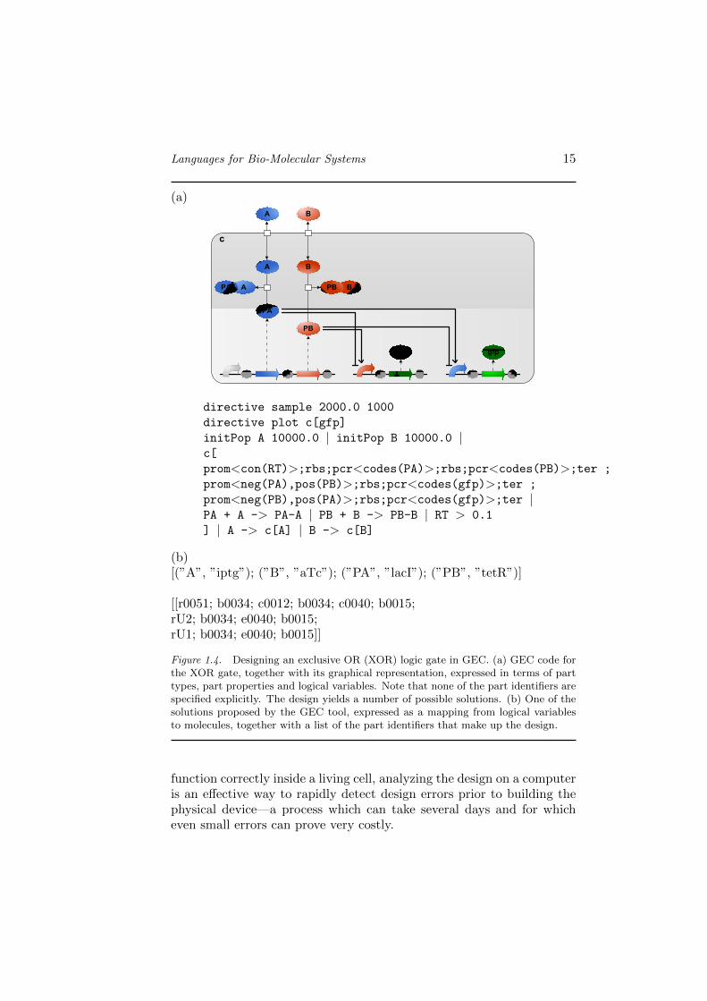
Figure 1.4. Designing an exclusive OR (XOR) logic gate in GEC. (a) GEC code forthe XOR gate, together with its graphical representation, expressed in terms of parttypes, part properties and logical variables. Note that none of the part identifiers arespecified explicitly. The design yields a number of possible solutions. (b) One of thesolutions proposed by the GEC tool, expressed as a mapping from logical variablesto molecules, together with a list of the part identifiers that make up the design.
function correctly inside a living cell, analyzing the design on a computeris an effective way to rapidly detect design errors prior to building thephysical device—a process which can take several days and for whicheven small errors can prove very costly.

16
We illustrate the design approach of the GEC language on a simpleexclusive OR (XOR) logic gate (Figure 1.4 on page 15). The system isspecified as a collection of three transcriptional units, where each unitconsists of a sequences of part types. The first transcriptional unit con-sists of a promoter (prom), a ribosome binding site (rbs) a protein codingregion (pcr), followed by another ribosome binding site and protein cod-ing region, followed by a terminator (ter):
prom; rbs; pcr; rbs; pcr; ter
Additional constraints on part types are specified in the form of partproperties. In the first transcriptional unit, the prom<con(RT)> de-notes a promoter with a constitutive transcription rate RT, the partpcr<codes(PA)> denotes a protein coding region that codes for pro-tein PA, and the part pcr<codes(PB)> denotes a protein coding regionthat codes for protein PB:
prom<con(RT)>; rbs; pcr<codes(PA)>; rbs; pcr<codes(PB)>; ter
The transcription rate RT and the proteins PA and PB start with an up-per case letter, which means that they are logical variables representingan unknown rate and unknown proteins. Although the values of thesevariables are not known in advance, the GEC compiler takes into ac-count the full set of design constraints in order to find suitable valuesthat satisfy the desired properties. For example, the property RT > 0.1
states that the constitutive transcription rate of the promoter must beabove a certain threshold. In the second transcriptional unit the partprom<neg(PA),pos(PB)> denotes a promoter region that is negativelyregulated by protein PA and positively regulated by protein PB:
prom<neg(PA),pos(PB)>; rbs; pcr<codes(gfp)>; ter
This places additional constraints on the proteins PA and PB, which mustact as a positive and negative regulator, respectively. The third tran-scriptional unit places further constraints on the proteins PA and PB,which must act as both positive and negative regulators simultaneously:
prom<neg(PB),pos(PA)>; rbs; pcr<codes(gfp)>; ter
Note that the protein gfp starts with a lower case letter, meaning thatit represents a known protein.
In order to map logical variables and design constraints to physi-cal parts, GEC includes a database of parts. Each of the parts in thedatabase is associated with a part identifier together with zero or morepart properties. A subset of a GEC parts database is shown in Table1.3 on page 17. The part properties are also associated with rate con-stants, which are used to simulate the design solutions. For example,

Languages for Bio-Molecular Systems 17
Table 1.3. A subset of the GEC parts database, which can be defined and extendedby the user. Each of the parts in the database is associated with a part identifiertogether with zero or more part properties.
ID Type Propertiese0040 pcr codes(gfp, 0.01)c0012 pcr codes(lacI,0.01)c0040 pcr codes(tetR, 0.01)b0034 rbs rate(0.1)b0015 terr0051 prom neg(cl, 1.0, 0.5, 0.00005), con(0.12)r0040 prom neg(tetR, 1.0, 0.5, 0.00005), con(0.09)rU1 prom neg(tetR,1.0,0.01,0.0), pos(lacI,1.0,0.5,0.1), con(0.0)rU2 prom neg(lacI,1.0,0.01,0.0), pos(tetR,1.0,0.5,0.1), con(0.0)rU3 prom neg(tetR,1.0,0.5,0.0), pos(lacI,1.0,0.5,0.1), con(0.0)
Table 1.4. A subset of the GEC reactions database, which can be defined and ex-tended by the user.
Reactants rate ProductslacI + iptg 1.0 lacI-iptgtetR + aTc 1.0 tetR-aTc
iptg 1.0 c[iptg]aTc 1.0 c[aTc]

18
the database entry (c0040 7→ pcr,codes(tetR, 0.01)) denotes a proteincoding region c0040, which codes for the protein tetR with degradationrate 0.01. The entry (r00517→prom,neg(cI,1.0,0.5, 0.00005),con(0.12))denotes a promoter r0051 that is negatively regulated by the proteincI, which binds to the promoter at rate 1.0 and unbinds at rate 0.5,where the repressed transcription rate is 0.00005 and the constitutivetranscription rate is 0.12.
The design of the XOR gate in Figure 1.4 on page 15 also includes in-teractions between proteins and transport reactions across the cell mem-brane. The following constraints require that the protein A binds to PA
and forms a complex PA-A, and that the protein B binds to PB and formsa complex PB-B. A vertical bar is used to separate multiple constraints:
PA + A -> PA-A | PB + B -> PB-B
This effectively specifies that the inputs A and B to the XOR gate caninhibit the activity of the transcription factors PA and PB by forminginert complexes with these transcription factors. Finally, the followingproperties require that both A and B are able to cross the cell wall:
A -> c[A] | B -> c[B]
These properties are essential in order for the input signals of the XORgate to be read by the cell. In order to map these reaction constraintsto physical parts, the GEC system includes a database of reactions.Each of the reactions in the database consists of a set of reactants, aset of products and a corresponding reaction rate. A subset of a GECreactions database is shown in Table 1.4 on page 17. For example,the reaction (lacI + iptg → {1.0} lacI-iptg) denotes the formation of acomplex between lacI and iptg. In many cases accurate rate informationfor these reactions is missing, and approximate rate constants are usedinstead.
The above design constraints for the XOR gate are solved by the GECcompiler in order to find an appropriate solution. For example, the firstprotein coding region of the first transcriptional unit must produce aprotein PA that can both inhibit the promoter of the second transcrip-tional unit, activate the promoter of the third transcriptional unit andalso form a complex with a compound that is capable of crossing the cellmembrane. In the general case multiple solutions are possible for a givendesign. One of the possible solutions is shown in Figure 1.4 on page 15.The solution maps the inputs A and B to iptg and aTc respectively, andthe transcription factors PA and PB to lacI and tetR, respectively. Thecorresponding part identifiers are also listed, which denote specific nu-cleotide sequences that could potentially be inserted inside a bacteriumin order to program an XOR gate.
Languages for Bio-Molecular Systems 19
The main characteristic of the XOR gate is that green fluorescentprotein (GFP) is only produced when one of the input signals A or Bis present, but not both. When the user compiles the XOR gate designin GEC, they are presented with a set of possible solutions that satisfythe design constraints. The user can then simulate each of the solutionsin order to choose the most desirable one. The design can be furtherrefined by specifying that certain rates such as transcription, translationor transcription factor binding must lie within a specified range. Thishelps to reduce the initial set of possible solutions. In the case of theXOR design, one of the solutions represents a condition whereby GFP isproduced even in absence of both inputs A and B. This occurs becausethe rate of repression of one of the promoters by transcription factor PAis less than its rate of activation by transcription factor PB, meaningthat activation out-competes inhibition. This unwanted solution canbe eliminated by adding the constraint that the inhibitor transcriptionfactors bind more tightly than the activator transcription factors.
In order to simulate a given design, GEC automatically compiles thedesign to a set of chemical reactions, using the rates associated withthe part properties and reactions in the GEC databases. The set ofreactions for the XOR gate design is summarized in Figure 1.7 on page21. Additional details about the compilation to reactions are providedin [Pedersen and Phillips, 2009a], and a screen shot of the tool is shownin Figure 1.6 on page 20.
In this section we have illustrated the design of genetic devices in GECusing a simple XOR gate as an example. In order to effectively designmore complex devices, however, further work is needed to characterizethe properties of individual parts. At present only a few parts are well-characterized and many reaction rates are unknown, so the part andreaction databases described here do not yet exist on a large scale. Asone potential consumer of such databases, GEC may help guide howthese they are designed and populated with information about biologicaldevices.
5. Proto
Proto is a truly high-level language for synthetic biology, in the sensethat a programmer specifies the computation they wish to execute, butthe implementation of that computation as a genetic regulatory networkis entirely automated. This greatly increases the power of the program-mer, at the cost of programs that typically consume more resources thanhand-tuned systems. The same sort of optimization techniques that ap-ply to conventional processors, however, can be applied to the genetic

20
No input aTc iptg aTc & iptg
Figure 1.5. Simulation of gfp concentration over time for an exclusive OR gate inGEC, with four combinations of inputs. The simulation uses the chemical reactions ofFigure 1.7 on page 21, which were automatically generated from the chosen solution ofFigure 1.4 on page 15. The solution exhibits the desired behavior and is a candidatefor synthesis.
Figure 1.6. Screen shot of the GEC tool in action. The GEC program is entered onthe left as a collection of part types, part properties and logical variables. The designis then compiled to a set of solutions, which can be individually selected. A givensolution can then be simulated by the tool in order to observe the expected evolutionof the molecular species over time.
regulatory networks generated by Proto, making this a reasonable ap-proach to designing complex synthetic biology systems.
Amorphous Medium and Proto
The original focus of Proto [Beal and Bachrach, 2006] was not syn-thetic biology, and synthetic biology is still not its primary focus. Rather,it was designed for programming spatial computers—potentially large

Languages for Bio-Molecular Systems 21
directive sample 2000.0 1000directive plot c[gfp]
rate mDeg = 0.001;init aTc 10000 |init iptg 10000 |c [
init glacI tetR 1 |mlacI tetR ->{mDeg} |glacI tetR->{0.12} glacI tetR +mlacI tetR |init ggfp1 1 |mgfp1 ->{mDeg} |ggfp1 ->{0.0} ggfp1 + mgfp1 |ggfp1+ lacI ->{1.0} ggfp1-lacI |ggfp1-lacI ->{0.01} ggfp1 + lacI |ggfp1-lacI ->{0.0} ggfp1-lacI +mgfp1 |ggfp1+ tetR ->{1.0} ggfp1-tetR |ggfp1-tetR ->{0.5} ggfp1 + tetR |ggfp1-tetR ->{0.1} ggfp1-tetR +mgfp1 |init ggfp2 1 |mgfp2 ->{mDeg} |ggfp2 ->{0.0} ggfp2 + mggfp2 |ggfp2+ tetR ->{1.0} ggfp2-tetR |ggfp2-tetR ->{0.01} ggfp2 + tetR |ggfp2-tetR ->{0.0} ggfp2-tetR +mgfp2 |ggfp2+ lacI ->{1.0} ggfp2-lacI |ggfp2-lacI ->{0.5} ggfp2 + lacI |ggfp2-lacI ->{0.1} ggfp2-lacI +mgfp2 |lacI + iptg ->{1.0} lacI-iptg | tetR+ aTc ->{1.0} tetR-aTc |mgfp2 ->{0.1} mgfp2 + gfp |mgfp1 ->{0.1} mgfp1 + gfp |mlacI tetR ->{0.1} mlacI tetR +lacI | mlacI tetR ->{0.1}mlacI tetR + tetR] |iptg->{1.0} c[iptg] |aTc->{1.0} c[aTc] |c [
gfp ->{0.01} |lacI ->{0.01} |tetR ->{0.01}]
Figure 1.7. Network of reactions generated from the design of Figure 1.4 on page 15.The graphical representation on the left was also generated by the GEC tool, and isequivalent to the textual representation on the right.
22
neighborhood of P
P
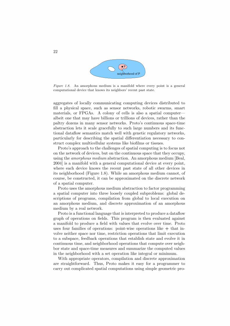
Figure 1.8. An amorphous medium is a manifold where every point is a generalcomputational device that knows its neighbors’ recent past state.
aggregates of locally communicating computing devices distributed tofill a physical space, such as sensor networks, robotic swarms, smartmaterials, or FPGAs. A colony of cells is also a spatial computer—albeit one that may have billions or trillions of devices, rather than thepaltry dozens in many sensor networks. Proto’s continuous space-timeabstraction lets it scale gracefully to such large numbers and its func-tional dataflow semantics match well with genetic regulatory networks,particularly for describing the spatial differentiation necessary to con-struct complex multicellular systems like biofilms or tissues.
Proto’s approach to the challenges of spatial computing is to focus noton the network of devices, but on the continuous space that they occupy,using the amorphous medium abstraction. An amorphous medium [Beal,2004] is a manifold with a general computational device at every point,where each device knows the recent past state of all other devices inits neighborhood (Figure 1.8). While an amorphous medium cannot, ofcourse, be constructed, it can be approximated on the discrete networkof a spatial computer.
Proto uses the amorphous medium abstraction to factor programminga spatial computer into three loosely coupled subproblems: global de-scriptions of programs, compilation from global to local execution onan amorphous medium, and discrete approximation of an amorphousmedium by a real network.
Proto is a functional language that is interpreted to produce a dataflowgraph of operations on fields. This program is then evaluated againsta manifold to produce a field with values that evolve over time. Protouses four families of operations: point-wise operations like + that in-volve neither space nor time, restriction operations that limit executionto a subspace, feedback operations that establish state and evolve it incontinuous time, and neighborhood operations that compute over neigh-bor state and space-time measures and summarize the computed valuesin the neighborhood with a set operation like integral or minimum.
With appropriate operators, compilation and discrete approximationare straightforward. Thus, Proto makes it easy for a programmer tocarry out complicated spatial computations using simple geometric pro-

Languages for Bio-Molecular Systems 23
grams that are robust to changes in the network and self-scale to net-works with different shape, diameter, density of nodes, and executionand communication properties [Bachrach et al., 2007].
For example, Weiss’ band detector [Basu et al., 2005] uses diffusingAHL to detect intermediate distance from a high aTc concentration.This can be implemented using the Proto program:
(def band-detect (signal lo hi)
(and (> signal lo) (< signal hi))))
(let ((signal (diffuse (aTc) 0.8 0.05)))
(green (band-detect signal 0.2 1)))
where aTc is a function for sensing aTc and green is an actuator thatsets the level of GFP expression. Figure 1.9 shows the Proto band de-tector program interpreted to produce a dataflow graph, then evaluatedagainst an irregularly shaped space. Executing the Proto band detec-tor in simulation produces results equivalent to Weiss’s band detector.Figure 1.10 compares execution on a network of 2000 simulated wirelessdevices distributed randomly through a 100 by 100 unit region with a10 unit communication radius to Weiss’ original results.
Motif-based compilation and optimization
Given a library of devices and standards to compile to, Proto programscan be transformed into genetic regulatory network designs by a processof motif-based compilation. The resulting design can then be optimizedusing adapted forms of standard code optimization techniques.
The basis of this compilation are associations of each Proto primi-tive to be compiled with a genetic regulatory network fragment. Theseare declared as annotations on primitives. For example, the logical notoperator is associated with a biological inverter motif by the statementshown in Figure 1.11. The first line declares the not operator as aprimitive that takes a boolean as input and returns a boolean as out-put. The second line annotates this declaration with a description ofa genetic regulatory region—in this case, a strong promoter repressedby whatever protein will represent the not operator’s input, followed bycoding regions for the proteins representing its outputs (each of which isimplicitly headed by the necessary ribosome binding site), then finally aterminator.
Motifs can include many other elements as well. For example, a motifcan specify particular chemicals to be used, as in the case of the greenactuator shown in Figure 1.12, whose green fluorescence side effect is im-plemented by the inclusion of a GFP coding region in the motif. Motifscan also include chemical reactions, as in the case of the IPTG sensor

24
Figure 1.9. A Proto program specifies a dataflow graph of operations on fields. Whenevaluated on a space, each operation produces a field of values over that space. Herethe band detector program is shown evaluated on an irregularly shaped space, withscalar fields grey (lighter is less) and boolean fields colored (true is red, false is blue).The actuation produced by green is shown inside that operation.
shown in Figure 1.13, which uses repression of LacI to detect the pres-ence of the small-molecule signal IPTG. They may even declare internalsignaling variables, to be filled in by the compiler, as in the case of theand operator shown in Figure 1.14, which implements a non-brancinglogical AND using inverter input to a NOR gate.
In order to transform a Proto dataflow computation into an abstractgenetic regulatory network, the compiler maps each operator to its as-sociated motif and maps each dataflow edge and internal motif variableto a regulatory protein. These motifs and proteins are then linked to-gether, using the structure of the dataflow graph, to form an abstractgenetic regulatory network. The particular choice of chemicals and se-quences to implement this network is not fully determined, but left fora later stage of compilation, such as might be provided by systems likeGEC [Pedersen and Phillips, 2009b] or Eugene [Berkeley Software 2009iGem Team, 2010]. An initial set of target chemical rate constants forthe network (to be modified as the implementation is determined) are

Languages for Bio-Molecular Systems 25
a
(a)
d
ba
c
(b)
Figure 1.10. Examples of the Weiss lab band detector in use (a, reprinted by permis-sion from Macmillan Publishers Ltd: Nature ([Basu et al., 2005]), copyright (2005)).The circular regions in the center are active sender bacteria, while the fuzzy areasaround them are receiver bacteria expressing fluorescent protein. A Proto implemen-tation produces equivalent results (b) on a network of 2000 simulated devices.
(primitive not (boolean) boolean :grn-motif ((P high R- arg0 outputs T)))
!"#$#%&"'()%*'*)+*',-.-/'&01"&..)#2
3&1"&..&4',5'#1&"-%#"')216% 7&"$)2-%#"
8#4)2+'9#"'#6%16%'1"#%&)2.
!"#$"#%&'()
Figure 1.11. Motif declaration for logical not operator.
(primitive green (scalar) scalar :side-effect :grn-motif ((P R+ arg0 GFP outputs T)))
!"#$#%&"'()%*'+#(',-.-+'&/0"&..)#1
21345&3',6'#0&"-%#"')104% 7&"$)1-%#"
8#3)19':#"'#4%04%'0"#%&)1.
8#3)19':#"';"&&1'<+4#"&.5&1%'!"#%&)1
!"# !"#$"#%&'()
Figure 1.12. Motif declaration for green fluorescence actuator.
filled in from the motifs where specified and filed in by a default set-pointin the standards family where not specified.
Consider, for example, the following declaration and use of logicalXOR to implement our example program:
(def xor (a b)
(or (and a (not b))
(and b (not a))))

26
(primitive IPTG () scalar :grn-motif ((rxn LacI IPTG -> LacI*) (P high LacI T) (P high R- LacI outputs T)))
!"#$#%&"'()*%+(+*,+(-.'./(&01"&''*#2
3.45(6&.4%*7.%&6(-8(-*26*2,(5!9:9&"$*2.%#"
;#6*2,(<#"(#=%1=%(1"#%&*2'
>&1"&''&6(-8(3.45
!"#$
$%&'
!"#$"#%
Figure 1.13. Motif declaration for IPTG sensor. An aTc sensor uses the same motif,except that aTc replaces IPTG and TetR replaces LacI.
(primitive and (boolean boolean) boolean :grn-motif ((P high R- arg0 ?X T) (P high R- arg1 ?X T) (P high R- ?X outputs T)))
!"#$#%&"'()*%+(+*,+(-.'./(&01"&''*#2
3&1"&''&4(-5(6*"'%(*217% 8&"$*2.%#"'
9#4*2,(6#"(#7%17%(1"#%&*2'
3&1"&''&4(-5('&:#24(*217%
9#4*2,(6#"($#%*6;*2%&"2./(1"#%&*2'
3&1"&''&4(-5($#%*6;*2%&"2./(1"#%&*2'
!"#$
!"#%
&'()'(*
!"
!"
Figure 1.14. Motif declaration for a non-branching logical AND operator. A logicalOR uses the same motif, except that all repressors are switched to activators andpromoters have low base activity.
!"#$%&'
()**%
+#,%&'
+%-
+%-
&)
Figure 1.15. A Proto dataflow computation implementing the XOR example pro-gram.
(green (xor (aTc) (IPTG)))
This program should create cells that fluoresce green when precisely oneof IPTG or aTc is present at high concentration.
This program is first interpreted to produce the dataflow computationshown in Figure 1.15. Each operator is then mapped to the motifs spec-ified by the declarations shown above. The dataflow edges are assignedto arbitrary regulatory proteins A, B, etc. The consuming motifs setthe type of protein, such that A and B are activators, C is a repressor,etc.

Languages for Bio-Molecular Systems 27
!"#$
$%&'
'(%
)
)
&*+,
"&#
-
$
.
/
0
!
!
(
1
1
2
3
'
Figure 1.16. A Proto dataflow computation is compiled to an abstract genetic reg-ulatory network in two stages. First, each operator is mapped to a motif and eachdataflow edge is mapped to a regulatory protein. These elements are then linkedtogether, using the structure of the dataflow graph, to form an abstract genetic reg-ulatory network.
We now have a genetic regulatory network design that implements ourhigh-level computation, though as yet it is still unoptimized and may beextremely inefficient. As we have demonstrated in [Beal and Bachrach,2008], standard code optimization techniques such as copy propagation,dead code elimination, and common subexpression elimination, can beadapted to operate on genetic regulatory networks.
!
!"
#"$%&
&'()
)*'
#
(+,-
$(% "
.
)
Figure 1.17. Optimized genetic regulatory network for XOR example.
For example, copy propagation tests whether a protein is being usedonly to copy a value; if so, the original input may be used directly ratherthan the copy. In this case of this XOR program, copy propagationchanges the input of the GFP-expressing element from A to J . This thenleaves protein A not regulating anything. Similarly, copy propagationswitches the regulation of J from B to K and from F to L.
Dead code elimination deletes proteins that are not regulating any-thing, network elements with no products, and proteins that can neverbe expressed. Since protein A is no longer regulating anything, it is

28
deleted, along with all of the protein coding sequences that can produceit. Since A was the only product of one of the network elements regu-lated by J , that whole network element is deleted. Likewise, B and Fand their producing elements are deleted by dead code elimination.
Another example of optimization is double negative elimination, whichlooks for sequences of two inverters and snips them out of the network.In the case of this XOR program, this results in changing the productionof E to production of K, since E’s only use is to repress D, which inturn represses K. Similarly production of I is changed to production ofL. This leaves I and E produced nowhere and D and H unable to beexpressed, so dead code elimination deletes another piece of unneededgenetic regulatory network.
These optimizations and more are all applied automatically by thecompiler, eventually resulting in the network shown in Figure 1.17. Alltold, the complexity of the generated network is reduced by approxi-mately 50% in every measure of complexity: from 15 to 8 proteins, from18 to 9 network elements, and from 7 to 4 stages of propagation delay.
We thus see that high-level computations specified in Proto can beautomatically transformed into an abstract genetic regulatory networkthrough a strategy of motif-based compilation. The resulting geneticregulatory network can be optimized using adapted forms of standardcode optimization techniques, and might then be mapped onto particularparts from a database using lower-level languages like Eugene or GEC.Although the network is more complex than a hand-optimized designlike those encoded in the other tools above, stronger optimizations willlikely be able to continue to close the gap, as they have for electroniccomputers.
6. Other High-Level Design Tools for BiologicalComputation
We have chosen to focus this chapter on high-level programming lan-guages for in vivo bio-molecular computation, where the metaphor ofcell as computer holds most strongly. There are a number of relatedareas outside of this scope, however, in which high-level design tools forbio-molecular systems have been developed, which we now briefly survey.
Macroizing CAD Tools. A number of synthetic biology designtools, such as TinkerCell [Chandran et al., 2009] and SynBioSS [Hillet al., 2008], use biological rules to aid the programmer in designingreaction networks. For example, SynBioSS (the Synthetic Biology Soft-ware Suite) is a software suite for the generation, storage, and quantita-

Languages for Bio-Molecular Systems 29
tive simulation of synthetic biological networks. One component of thissoftware suite, called SynBioSS Designer, uses biological rules to createa reaction network given a series of biological parts, such as promotersand ribosome binding sites, and the spatial and temporal connectivityof these parts.
These systems also frequently include the ability to abstract a portionof the network being designed. This type of “macroization” is a steptoward a high-level language: the details of the abstracted portion arehidden and it can be given a name that describes its overall function.The programmer must still be aware of the details, however, since theset of parts in the abstracted sub-network are fixed and can interferewith other portions of the design.
Specialized Automated Design Tools. Complementary toMacroizing CAD tools are specialized automated design tools, whichmight be thought of as limited high-level languages. An example is theboolean circuit design tool recently described in [Marchisio and Stelling,2010]. Given a truth table mapping inputs to desired outputs, this toolapplies the Karnaugh map method from electronic circuit design to finda minimal set of boolean formulas, then maps these formulas onto alibrary of established bio-molecular boolean gates.
Cell-free Bio-Molecular Computation. A number of bio-molecular computation systems have been constructed to operate in cell-free in vitro environments, and the design challenges for many of thesesystems are being addressed with high-level design tools. For example,the VERB compiler [Shea et al., 2009] transforms circuit designs writtenin Verilog into a biochemical reaction network, and CAD tools have beenwritten to generate DNA origami structures [Rothemund, 2005].
Bio-Inspired Languages. There are a number of biologically-inspired languages that have been designed to mimic the behavior of en-gineered biological systems. For the most part, these are at a level of ab-straction too high to currently be able to map to a bio-molecular systemsimplementation, though Weiss’ Microbial Colony Language [Weiss, 2001]is close. Many of these languages are focused on pattern formation, suchas the Origami Shape Language [Nagpal, 2001], which develops geomet-ric structure through folding, the Growing Point Language [Coore, 1999],which develops topological structure through tropisms. Yet others eithermodel high-level biological development without connection to the de-tails necessary to implement it, as in the case of L-systems [Prusinkiewiczand Lindenmayer, 1990] and MGS [Giavitto et al., 2002], or use biologi-

30
cal metaphors for decidedly non-biological programming, as in the caseof membrane computing [Paun, 2002].
Modeling languages. Biological modeling languages such as Anti-mony [Smith et al., 2009], ProMoT [Mirschel et al., 2009], iBioSim [My-ers et al., 2009] and little b [Mallavarapu et al., 2009] raise the level of ab-straction for constructing models of bio-molecular reactions, but do notdirectly address the problem of designing computations. For example,Antimony is a modular model definition language that allows scientiststo define and use reaction networks. It is designed to be human-writableand acts as an extension to other tools by translating the model toSBML [Finney et al., 2006]. Antimony models composable DNA partsand also allows reaction networks to be abstracted and parameterized,but does not provide any design automation for its user.
7. Summary
In this chapter, we have examined four high-level languages for thedesign of bio-molecular computing systems. Although the philosophyand the level of abstraction varies between systems, all are fulfillingthe same basic goal of hiding complexity from the programmer. Eachthus allows a programmer to specify the computing system they wishto create without the full details of how it will be implemented, thenautomatically generates the remaining details.
At present, none of the available high-level languages can be consid-ered mature. They are, however, an important and rapidly developingresearch area. Major challenges in the near future for this area include:
Development of concise high-level abstractions that map well toefficient bio-molecular implementations of a broad range of goals.
Enhancing the range and quality of automation.
Integration with other simulation, design, and assembly tools toform complete tool-chains.
Transitioning from research software to production quality soft-ware.
Assuming that progress continues in these areas, however, the advent ofhigh-level programming languages for bio-molecular systems is likely tofundamentally transform the field, much as they have done in computerscience, by enabling much more complex bio-molecular systems to bedesigned more reliably by a vastly larger number of practitioners.
References
[Bachrach et al., 2007] Bachrach, Jonathan, Beal, Jacob, and Fujiwara,Takeshi (2007). Continuous space-time semantics allow adaptive pro-gram execution. In IEEE SASO 2007.
[Basu et al., 2005] Basu, Subhayu, Gerchman, Yoram, Collins, Cyn-thia H., Arnold, Frances H., and Weiss, Ron (2005). A syntheticmulticellular systems for programmed pattern formation. Nature,434:1130–1134.
[Beal, 2004] Beal, Jacob (2004). Programming an amorphous computa-tional medium. In Unconventional Programming Paradigms Interna-tional Workshop.
[Beal and Bachrach, 2006] Beal, Jacob and Bachrach, Jonathan (2006).Infrastructure for engineered emergence in sensor/actuator networks.IEEE Intelligent Systems, pages 10–19.
[Beal and Bachrach, 2008] Beal, Jacob and Bachrach, Jonathan (2008).Cells are plausible targets for high-level spatial languages. In SpatialComputing Workshop.
[Berkeley Software 2009 iGem Team, 2010] Berkeley Software 2009iGem Team (October 2009, Retrieved May 10, 2010.). Eugene.http://2009.igem.org/Team:Berkeley Software/Eugene.
[Cai et al., 2007] Cai, Yizhi, Hartnett, Brian, Gustafsson, Claes, andPeccoud, Jean (2007). A syntactic model to design and verify syntheticgenetic constructs derived from standard biological parts. Bioinfor-matics, 23(20):2760–7.
[Cai et al., 2009] Cai, Yizhi, Lux, Matthew W, Adam, Laura, and Pec-coud, Jean (2009). Modeling structure-function relationships in syn-thetic dna sequences using attribute grammars. PLoS Comput Biol,5(10):e1000529.

32
[Cai et al., 2010] Cai, Yizhi, Wilson, Mandy L, and Peccoud, Jean(2010). Genocad for igem: a grammatical approach to the designof standard-compliant constructs. Nucleic Acids Res, 38(8):2637–44.
[Chandran et al., 2009] Chandran, Deepak, Bergmann, Frank, andSauro, Herbert (2009). Tinkercell: modular cad tool for syntheticbiology. Journal of Biological Engineering, 3(1):19.
[Chomsky, 1956] Chomsky, N. (1956). Three models for the descriptionof language. Information Theory, IRE Transactions on, 2(3):113–124.
[Coore, 1999] Coore, Daniel (1999). Botanical Computing: A Develop-mental Approach to Generating Inter connect Topologies on an Amor-phous Computer. PhD thesis, MIT.
[Czar et al., 2009] Czar, Michael J, Cai, Yizhi, and Peccoud, Jean(2009). Writing dna with genocad. Nucleic Acids Res, 37(Web Serverissue):W40–7.
[Densmore et al., 2010] Densmore, Douglas, Hsiau, Timothy H-C, Kit-tleson, Joshua T, DeLoache, Will, Batten, Christopher, and Anderson,J Christopher (2010). Algorithms for automated dna assembly. Nu-cleic Acids Res, 38(8):2607–16.
[Densmore et al., 2009] Densmore, Douglas, Van Devender, Anne, John-son, Matthew, and Sritanyaratana, Nade (2009). A platform-baseddesign environment for synthetic biological systems. In TAPIA ’09:The Fifth Richard Tapia Celebration of Diversity in Computing Con-ference, pages 24–29, New York, NY, USA. ACM.
[Finney et al., 2006] Finney, Andrew, Hucka, Michael, Bornstein, Ben-jamin J., Keating, Sarah M., Shapiro, Bruce M., Matthews, Joanne,Kovitz, Benjamin K., Schilstra, Maria J., Funahashi, Akira, Doyle,John, and Kitano, Hiroaki (2006). Software infrastructure for effec-tive communication and reuse of computational models. In Szallasi,Zoltan, Stelling, Jorg, and Periwal, Vipul, editors, System Modelingin Cell Biology: From Concepts to Nuts and Bolts. MIT Press.
[Giavitto et al., 2002] Giavitto, Jean-Louis, Godin, Christophe, Michel,Olivier, and zemyslaw Prusinkiewicz, Pr (2002). Computational mod-els for integrative and developmental biology. Technical Report 72-2002, Univerite d’Evry, LaMI.
[Hill et al., 2008] Hill, Anthony D., Tomshine, Jonathan R., Weeding,Emma M. B., Sotiropoulos, Vassilios, and Kaznessis, Yiannis N.

REFERENCES 33
(2008). Synbioss: the synthetic biology modeling suite. Bioinformat-ics, 24(21):2551–2553.
[Mallavarapu et al., 2009] Mallavarapu, Aneil, Thomson, Matthew, Ul-lian, Benjamin, and Gunawardena, Jeremy (2009). Programming withmodels: modularity and abstraction provide powerful capabilities forsystems biology. Journal of The Royal Society Interface, 6(32):257–270.
[Marchisio and Stelling, 2010] Marchisio, Mario Andrea and Stelling,Jorg (2010). Automatic design of digital synthetic gene circuits. In2nd International Workshop on Bio-Design Automation.
[Mirschel et al., 2009] Mirschel, S., Steinmetz, K., Rempel, M., Ginkel,M., and Gilles, E. D. (2009). Promot: Modular modeling for systemsbiology. Bioinformatics, 25(5):687–689.
[Myers et al., 2009] Myers, C.J., Barker, N., Jones, K., Kuwahara, H.,Madsen, C., and Nguyen, N.P. (2009). ibiosim: a tool for the analysisand design of genetic circuits. Bioinformatics, 25:2848–9.
[Nagpal, 2001] Nagpal, Radhika (2001). Programmable Self-Assembly:Constructing Global Shape using Biologically-inspired Local Interac-tions and Origami Mathematics. PhD thesis, MIT.
[Nathan J. Hillson, 2010] Nathan J. Hillson (Retrieved September 28,2010.). j5 automated dna assembly software. http://jbei-exwebapp.lbl.gov/j5.
[Paun, 2002] Paun, G. (2002). Membrane computing: An introduction.Springer.
[Pedersen and Phillips, 2009a] Pedersen, Michael and Phillips, Andrew(2009a). Towards programming languages for genetic engineering ofliving cells. J R Soc Interface, 6 Suppl 4:S437–S450.
[Pedersen and Phillips, 2009b] Pedersen, Michael and Phillips, Andrew(2009b). Towards programming languages for genetic engineering ofliving cells. Journal of the Royal Society Interface.
[Prusinkiewicz and Lindenmayer, 1990] Prusinkiewicz, Przemyslaw andLindenmayer, Aristid (1990). The Algorithmic Beauty of Plants.Springer-Verlag, New York.
[Purnick and Weiss, 2009] Purnick, Priscilla E M and Weiss, Ron(2009). The second wave of synthetic biology: from modules to sys-tems. Nat Rev Mol Cell Biol, 10(6):410–422.

34
[Rothemund, 2005] Rothemund, Paul W. K. (2005). Design of dnaorigami. In International Conference on Computer-Aided Design (IC-CAD).
[Shea et al., 2009] Shea, Adam, Fett, Brian, Riedel, Marc, and Parhi,Keshab (2009). Writing and compiling code into biochemistry. InInternational Conference on Computer-Aided Design.
[Smith et al., 2009] Smith, Lucian P., Bergmann, Frank T., Chandran,Deepak, and Sauro, Herbert M. (2009). Antimony: a modular modeldefinition language. Bioinformatics, 25(18):2452–54.
[Sudkamp, 2006] Sudkamp, Thomas A (2006). Languages and machines:an introduction to the theory of computer science. Pearson Addison-Wesley, Boston, 3rd ed edition.
[Weiss, 2001] Weiss, Ron (2001). Cellular Computation and Communi-cations using Engineered Genetic Regulatory Networks. PhD thesis,MIT.