High-Frequency Power Transformers with Foil Windings ...
12
1 Abstract— Foil conductors and primary and secondary interleaving are normally used to minimize winding losses in high-frequency transformers used for high-current power applications. However, winding interleaving complicates the transformer assembly, since taps are required to connect the winding sections, and also complicates the transformer design, since it introduces a new tradeoff between minimizing losses and reducing the construction difficulty. This paper presents a novel interleaving technique, named maximum interleaving, that makes it possible to minimize the winding losses as well as the construction difficulty. An analytical design methodology is also proposed in order to obtain free-cooled transformers with a high efficiency, low volume and, therefore, a high power density. For the purpose of evaluating the advantages of the proposed maximum interleaving technique, the methodology is applied to design a transformer positioned in the 5 kW-50 kHz intermediate high-frequency resonant stage of a commercial PV inverter. The proposed design achieves a transformer power density of 28 W/cm 3 with an efficiency of 99.8%. Finally, a prototype of the maximum-interleaved transformer is assembled and validated satisfactorily through experimental tests. Index Terms— Foil windings, high-frequency, maximum interleaving, optimization, transformer design. I. INTRODUCTION or applications requiring galvanic isolation, the line- frequency transformer has traditionally been the heaviest, most expensive and least efficient component part of an electronic power converter. Nowadays, there is a large number of medium power applications (1-25 kVA) with a limited weight and space, such as electric traction systems, distributed generation systems (PV panels and mini-wind turbines) and power supplies, in which cost and efficiency are paramount. In these applications, one of the most widely adopted solutions for achieving considerable reductions in weight and volume whilst significantly increasing efficiency, yet still maintaining the required galvanic isolation, is to Manuscript received September 15, 2014; accepted November 03, 2014. Copyright © 2014 IEEE. Personal use of this material is permitted. However, permission to use this material for any other purposes must be obtained from the IEEE by sending a request to [email protected]. This work was supported in part by the Spanish Ministry of Economy and Competitiveness under Grants DPI2010-21671-C02-01 and DPI2013-42853-R and by the Public University of Navarre. The authors are with the Department of Electrical and Electronic Engineering, Public University of Navarre, Pamplona, Spain (e-mail: [email protected]; [email protected]; [email protected]; [email protected]; [email protected]). increase the transformer operating frequency to the range of 1-150 kHz [1]–[4]. In order to reduce winding loss, the primary and secondary windings of high-frequency (HF) transformers are usually sectioned and interleaved, and special wire geometries, such as litz and foil conductors, are used [5]–[7]. Compared to litz wire, a foil conductor is preferred due to its higher width-to- thickness ratios, which provide lower DC resistances and higher fill factors, its better heat conduction which facilitates heat transfer to the environment, and its lower cost [1], [8]. However, the conventional procedure for interleaving foil windings complicates the transformer assembly since taps are required to connect in series the beginning and end of each winding section. Although special techniques have been proposed to interleave windings and minimize both losses and assembly difficulty [8], [9], they have limitations since they are only applicable either to transformers with turns ratios that are close to the unity or to planar transformers. Furthermore, the design of HF transformers needs to address the interdependence between core sizing, foil thickness sizing and winding interleaving, which complicates the design process. The problem is usually solved by means of an iterative process that depends on the designer's experience and may entail the omission of some of the complex electromagnetic, thermal and construction interdependencies existing amongst the design parameters [5]–[7], [10]–[14]. To address the challenge of optimal HF transformer design, this work proposes firstly an innovative technique, termed maximum interleaving, which makes it possible to minimize losses whilst minimizing the number of taps required and, consequently, the construction difficulty. Then, a novel non-iterative analytical methodology to optimally design HF transformers is proposed, leading to the direct resolution of the design problem as a non-linear optimization problem of only four design variables. The methodology comprehensively formulates the complex multi-physical phenomena present in the operation of a HF transformer and the dependencies that arise between these phenomena in the transformer design process. Moreover, given the fact that winding interleaving may not be advisable in some applications, such as when a high leakage inductance or a low interwinding capacitance is required or in high voltage applications, the scope of the design methodology proposed in this paper is extended to High-Frequency Power Transformers with Foil Windings: Maximum Interleaving and Optimal Design Ernesto L. Barrios, Student Member, IEEE, Andoni Urtasun, Student Member, IEEE, Alfredo Ursúa, Member, IEEE, Luis Marroyo, Member, IEEE, and Pablo Sanchis, Senior Member, IEEE F
Transcript of High-Frequency Power Transformers with Foil Windings ...
1
Abstract— Foil conductors and primary and secondary
interleaving are normally used to minimize winding losses in high-frequency transformers used for high-current power applications. However, winding interleaving complicates the transformer assembly, since taps are required to connect the winding sections, and also complicates the transformer design, since it introduces a new tradeoff between minimizing losses and reducing the construction difficulty. This paper presents a novel interleaving technique, named maximum interleaving, that makes it possible to minimize the winding losses as well as the construction difficulty. An analytical design methodology is also proposed in order to obtain free-cooled transformers with a high efficiency, low volume and, therefore, a high power density. For the purpose of evaluating the advantages of the proposed maximum interleaving technique, the methodology is applied to design a transformer positioned in the 5 kW-50 kHz intermediate high-frequency resonant stage of a commercial PV inverter. The proposed design achieves a transformer power density of 28 W/cm3 with an efficiency of 99.8%. Finally, a prototype of the maximum-interleaved transformer is assembled and validated satisfactorily through experimental tests.
Index Terms— Foil windings, high-frequency, maximum interleaving, optimization, transformer design.
I. INTRODUCTION or applications requiring galvanic isolation, the line-frequency transformer has traditionally been the
heaviest, most expensive and least efficient component part of an electronic power converter. Nowadays, there is a large number of medium power applications (1-25 kVA) with a limited weight and space, such as electric traction systems, distributed generation systems (PV panels and mini-wind turbines) and power supplies, in which cost and efficiency are paramount. In these applications, one of the most widely adopted solutions for achieving considerable reductions in weight and volume whilst significantly increasing efficiency, yet still maintaining the required galvanic isolation, is to
Manuscript received September 15, 2014; accepted November 03, 2014. Copyright © 2014 IEEE. Personal use of this material is permitted.
However, permission to use this material for any other purposes must be obtained from the IEEE by sending a request to [email protected].
This work was supported in part by the Spanish Ministry of Economy and Competitiveness under Grants DPI2010-21671-C02-01 and DPI2013-42853-R and by the Public University of Navarre.
The authors are with the Department of Electrical and Electronic Engineering, Public University of Navarre, Pamplona, Spain (e-mail: [email protected]; [email protected]; [email protected]; [email protected]; [email protected]).
increase the transformer operating frequency to the range of 1-150 kHz [1]–[4].
In order to reduce winding loss, the primary and secondary windings of high-frequency (HF) transformers are usually sectioned and interleaved, and special wire geometries, such as litz and foil conductors, are used [5]–[7]. Compared to litz wire, a foil conductor is preferred due to its higher width-to-thickness ratios, which provide lower DC resistances and higher fill factors, its better heat conduction which facilitates heat transfer to the environment, and its lower cost [1], [8]. However, the conventional procedure for interleaving foil windings complicates the transformer assembly since taps are required to connect in series the beginning and end of each winding section. Although special techniques have been proposed to interleave windings and minimize both losses and assembly difficulty [8], [9], they have limitations since they are only applicable either to transformers with turns ratios that are close to the unity or to planar transformers.
Furthermore, the design of HF transformers needs to address the interdependence between core sizing, foil thickness sizing and winding interleaving, which complicates the design process. The problem is usually solved by means of an iterative process that depends on the designer's experience and may entail the omission of some of the complex electromagnetic, thermal and construction interdependencies existing amongst the design parameters [5]–[7], [10]–[14].
To address the challenge of optimal HF transformer design, this work proposes firstly an innovative technique, termed maximum interleaving, which makes it possible to minimize losses whilst minimizing the number of taps required and, consequently, the construction difficulty. Then, a novel non-iterative analytical methodology to optimally design HF transformers is proposed, leading to the direct resolution of the design problem as a non-linear optimization problem of only four design variables. The methodology comprehensively formulates the complex multi-physical phenomena present in the operation of a HF transformer and the dependencies that arise between these phenomena in the transformer design process.
Moreover, given the fact that winding interleaving may not be advisable in some applications, such as when a high leakage inductance or a low interwinding capacitance is required or in high voltage applications, the scope of the design methodology proposed in this paper is extended to
High-Frequency Power Transformers with Foil Windings: Maximum Interleaving and Optimal
Design Ernesto L. Barrios, Student Member, IEEE, Andoni Urtasun, Student Member, IEEE, Alfredo Ursúa,
Member, IEEE, Luis Marroyo, Member, IEEE, and Pablo Sanchis, Senior Member, IEEE
F
2
include a non-interleaved approach. This is then used as a reference point to assess the advantages of the maximum interleaving technique.
The paper is organized as follows. Section II presents the models for the calculation of the core loss, foil winding loss and transformer thermal resistance for use in the design process. Section III explains the maximum interleaving and the winding loss calculation when this technique is applied. Section IV discusses the transformer design problem and proposes the optimal design methodology. With this methodology two theoretical designs for a PV application are obtained in Section V, one with maximum-interleaved and the other with non-interleaved windings. When comparing both designs, the maximum interleaving design achieves the best performance in terms of power density and efficiency. A prototype for the maximum interleaving design is then built in Section VI, paying particular attention to the assembly process and the use of low-cost standardized materials. The prototype is finally validated by means of experimental tests with satisfactory results.
II. TRANSFORMER MODELING
A. Core Loss and Geometry In the transformer design, the calculation of the core loss is
made in practice through empirical formula based on the Steinmetz equation [15]. For typical HF power transformer applications, in which the voltage applied is rectangular in form, with or without zero voltage periods, the modified Steinmetz equation (MSE) [16], the improved generalized Steinmetz equation (iGSE) [17], and the improved iGSE (i2GSE) [18] have been shown to be accurate core loss empirical models [18]–[20]. Each model improves the accuracy of the previous one but with an increasing complexity. Thus, the MSE is generally used to calculate the core loss in design processes due to its good trade-off between accuracy and simplicity [12]. Its expression is [16]:
( ) ( ) cTopeTopeTy
px
eqmc VcccBffCP ⋅+⋅−⋅⋅⋅⋅⋅= −01
22
1 ττ (1) where f is the applied voltage waveform frequency, Bp is the magnetic induction amplitude, τope is the operating temperature of the magnetic material, Vc is the magnetic core volume, Cm, x, and y, and cT2, cT1 and cT0 are the losses and temperature coefficients for the material, respectively, as provided by the manufacturers in their datasheets, and feq is the equivalent frequency:
dtdtdB
Bf
T
eq ∫
⋅=
0
2
222
π∆. (2)
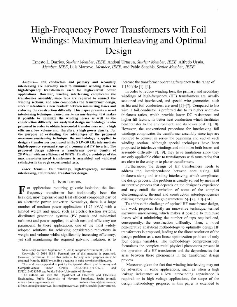
Fig. 1 shows the geometry of the double U and double E cores commonly used in power applications. Traditionally, the core geometry is characterized by five characteristic dimensions: mean length turn of a winding that completely fills the window (MLTc), equivalent volume including the core and windings (Ve), effective cross-sectional area of the core (Ac), window area (Aw), and core volume (Vc). The latter three dimensions only depend on the type of core whilst the first
two also depend on the place where the windings are wound. Table I shows, for the two most common winding and core types, the five characteristic dimensions based on the three non-dimensional coefficients c1, c2, c3 and the dimensional factor a defined in Fig. 1. In the fourth column, the characteristic dimensions are expressed based on the characteristic coefficients mltc, ve, ac, aw, vc and the dimensional factor a in order to facilitate its use in the design process.
(a) (b) Fig. 1. Characteristic dimensions MLTc, Ac, Aw, and Vc, dimensional factor
a and form coefficient c1, c2, and c3, for the main power cores: (a) double U and (b) double E.
By applying these generic form expressions, the core loss can be expressed as follows:
ypc BaKP ⋅⋅= 3
1 (3) where coefficient K1 is:
( )012
21 TTTcx
mmag cccvfCkK +⋅−⋅⋅⋅⋅⋅= ττ (4) where kmag is the ratio between the losses for a non-sinusoidal magnetic induction and those for a sinusoidal one, and can be expressed as a function of the length of the zero-voltage period in rad, θ, as follows [19]:
11
2 18 −−−
−⋅
=
xyx
magkπθ
π. (5)
B. Foil Winding Losses When operating at high frequencies, the amplitude and non-
uniformity of the current density distribution in the winding cross-sectional area increases due to the well-known skin and
a c1·a
Aw
Ac
Vc
MLTc
c2·a
c3·a
a c1·a
Aw
Ac
MLTc
Vc
c2·a
c3·a
TABLE I . CHARACTERISTIC DIMENSIONS FOR MAIN POWER CORES: DOUBLE E AND DOUBLE U
Core characteristic dimensions
Only one leg double U
Shell type double E
Generic form
MLTc 2·(2c1+c3+1)·a 2·(2c1+c3+1)·a mlt·a
Ve 2·(c1+1)·(c2+2) ·(c3+c1)·a3
2·(c1+1)·(c2+1) ·(c3+2·c1)·a3 ve·a3
Ac c3·a2 c3·a2 ac·a2 Aw c1·c2·a2 c1·c2·a2 aw·a2 Vc 2c3(c1+c2+2)a3 2c3(c1+c2+5/4)a3 vc·a3
3
proximity effects. This can lead to an increase in winding loss. In order to reduce this increase as far as possible foil conductors are used. The calculation of the foil winding loss has aroused great interest since Dowell’s work [21] and its generalization in [22] until nowadays [23]. The power loss in a foil winding section of p layers filling the full window height with thickness h is calculated in this work by means of the expression proposed by Snelling in [24] based on the approximation of the analysis made by Dowell in [21] for h ≤ δ:
−
+⋅⋅=42
2
45151
δhpIRP rmsdcw (6)
where Irms is the rms winding current, δ is the skin depth, and Rdc is the dc resistance. The expressions for these latter two parameters are:
µσπ
δ⋅⋅⋅
=if
1 , (7)
f
wdc wh
NMLTR⋅⋅
⋅=
σ (8)
where fi is the current waveform frequency, MLTw is the mean length turn of the winding, N is the number of turns, σ is the material conductivity, μ is the magnetic permeability and wf is the foil height. When the foil thickness is greater than the skin depth, this expression overestimates the winding loss.
C. Thermal Modeling It is possible to use both theoretical and empirical models to
estimate the thermal resistance of the transformer in a steady state. A wide range of theoretical thermal models are available, depending on the heat transfer mechanisms considered and their interpretation. Empirical models achieve a similar accuracy to theoretical ones, but with greater simplicity [6], [11], and are therefore generally preferred for use in the design process. In fact, the value of the transformer thermal resistance Rth is probably the most uncertain parameter in the entire transformer design [13]. Studies made by the magnetic material manufacturers show that it is possible to establish an empirical relationship between the thermal resistance of the transformer and the volume of its core [25], [26]. Based on the data included by the manufacturers in their application notes for various double E and double U ferrite cores, for a temperature increase of 50 ºC, and including the core volume in its generic form as shown in Table I, the empirical formula for the thermal resistance Rth of a naturally-cooled transformer is as follows:
56.152.0
0457.0av
Rc
th⋅
= (9)
where Rth is expressed in ºC/W, vc is a non-dimensional factor and a is expressed in meters. Very similar expressions are commonly used in design processes for soft magnetic materials with relatively high thermal conductivity such as ferrites, nanocrystalline, and amorphous iron alloys [7].
III. MAXIMUM INTERLEAVING: OPTIMAL WINDING DISTRIBUTION
A. Conventional Interleaving Thanks to the presence of a secondary winding, it is
possible to reduce the amplitude of the magnetomotive force (fmm) in the window responsible for the proximity effect. With this end, primary and secondary windings are usually divided into sections and interleaved. The interleaving reduces the number of layers per section p and, thus, as can be seen from applying (6), also the losses in the interleaved winding. However, this entails considerable construction difficulty as, in order to series-connect the last turn of one section with the start of the following section, taps need to be made. As a result, the maximum feasible interleaving is limited by this construction complexity [5], [8].
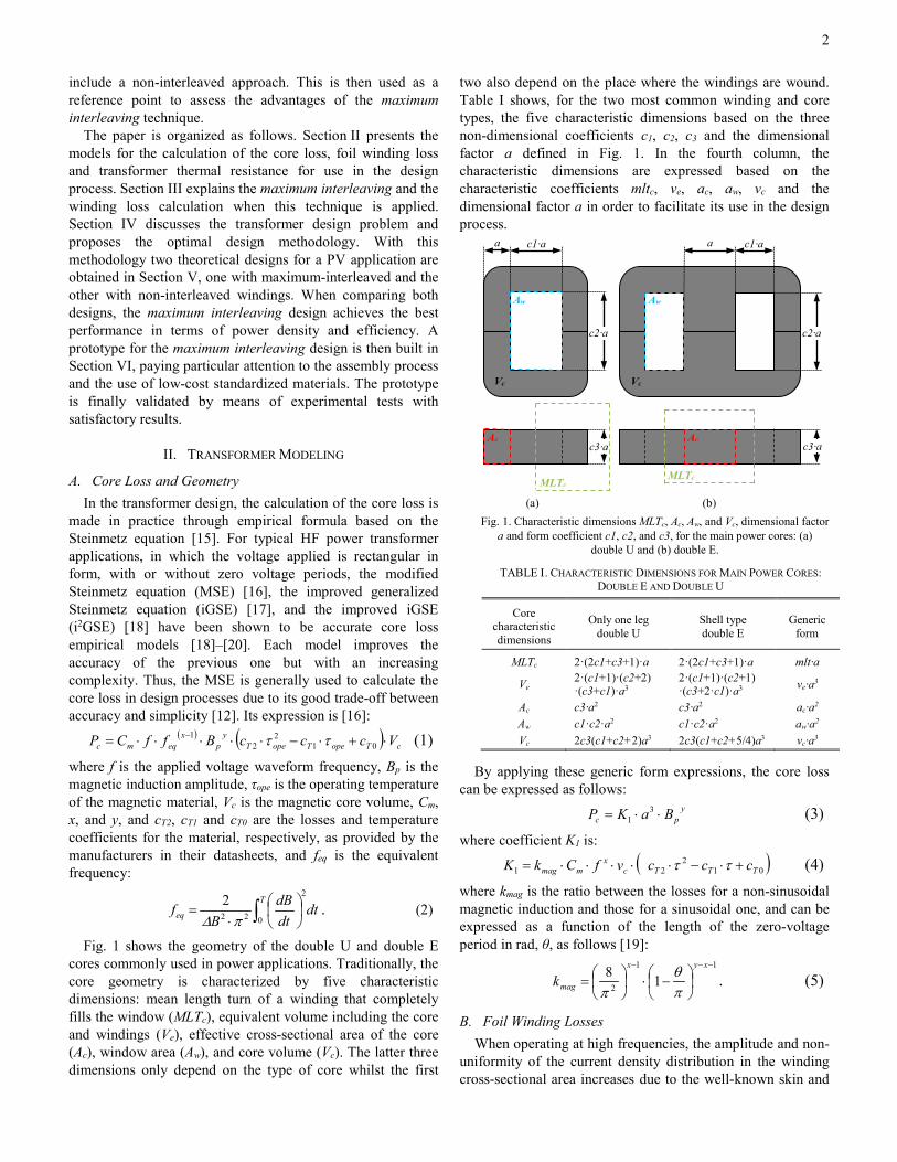
Considering now an example in which four turns for the primary and eight for the secondary are required with primary current value i, Fig. 2 shows three different possible winding configurations and their resultant fmm distributions. As indicated in Fig. 2 (a), one option is to make a 4-8 winding arrangement, i.e. no interleaving, having a primary section with four turns (p=4) and a secondary section with eight (p=8). Consequently, maximum values are obtained for the fmm and proximity effect losses, and no taps are required, thereby the winding process difficulty is minimum.
As shown in Fig. 2 (b), another option is to divide the windings into two groups with a 2-4 configuration. This is an intermediate interleaving comprising two primary sections with two turns each (p=2) and two secondary sections with four turns each (p=4). In this case, in comparison with the first option above, the maximum fmm has been halved, leading to lower losses. However, the construction process is more complicated, consisting in making two turns with the insulated primary foil and then cutting it. The insulated secondary foil is then wrapped around the primary and cut. The process is then repeated, but when starting the second primary section, the end of the first section needs to be connected to the beginning of this second section. This connection is called a tap. The same procedure is followed for tapping the secondary sections. This interleaving level is an acceptable trade-off between losses and construction difficulty [5] and, therefore, manufacturers do not usually continue increasing the interleaving.
When the number of layers per section for the primary and secondary is minimized, the windings are fully interleaved and the fmm and the proximity effect losses are also minimized. However, this design creates the greatest construction difficulty, requiring the higher number of cuts and taps. As indicated in Fig. 2 (c), in the example studied, the windings are fully interleaved when four groups are formed with a 1-2 configuration. Consequently, six taps are needed; three taps to series-connect the primary turns and another three to series-connect the end of each secondary section with the beginning of the next.

4
(a) (b) (c)
Fig. 2. Magnetomotive force in the cross section of a transformer window for three different winding interleaving arrangements: (a) non-interleaved,
(b) intermediate interleaving, and (c) fully interleaved.
It should be pointed out that the interleaving affects the parasitic elements of the transformer. The greater the interleaving, the lower the energy stored in the stray magnetic field and the greater the energy stored in the stray electric field between the primary and secondary windings. In this way, the greater the interleaving, the lower the leakage inductance and the greater the capacity between the primary and secondary windings [7]. Consequently, depending on the application, the interleaving may not be advisable. For instance, when electromagnetic interference (EMI) needs to be minimized, when leakage inductance is used as a filter or resonant components [27], [28], or in high voltage applications in which primary and secondary windings are grouped into separate chambers due to isolation concern, a non-interleaved structure is preferred.
B. Maximum Interleaving of Foil Windings In order to maximize the reduction of the proximity effect
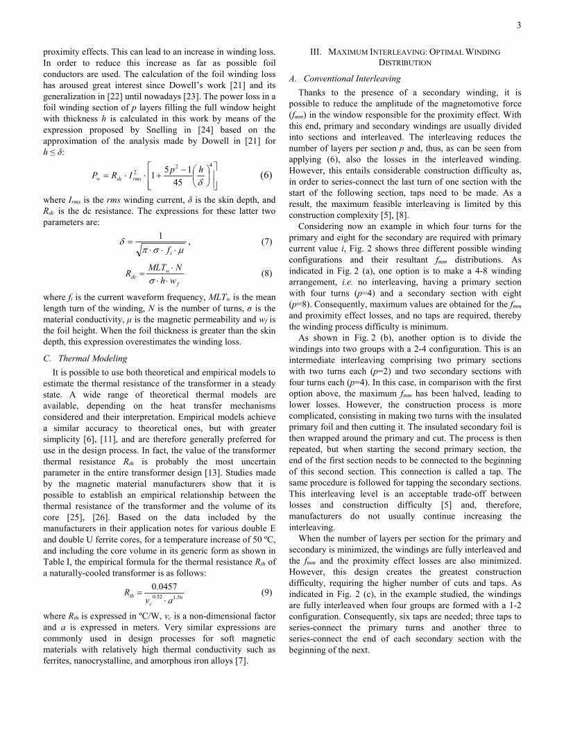
yet without a complicated assembly, a new winding interleaving technique, named maximum interleaving, is proposed in this paper. With this technique, the fmm distribution is the same as for the conventional fully-interleaved winding configuration, however, due to the construction process proposed, the number of taps required is reduced to the minimum technically necessary. In order to make it easier to understand the proposed technique, this is firstly applied to the example above (see Fig. 3) and it is then generically described.
In the first step, three insulated foils are wound around the magnetic core’s central leg to make four turns. The first foil has the primary winding thickness, while the second and third foils have the secondary thickness. Finally, and as detailed in Fig. 3, the beginning of the third foil is soldered to the end of the second foil through a tap, so that the second and third foils are series connected and eight turns for the secondary winding are completed. In so doing, the same minimum losses as for conventional full interleaving are achieved yet with a much simpler construction, given the fact that only one tap is needed instead of the conventional six.
The maximum interleaving technique proposed in this paper is generically described below. It can be easily applied to any transformer ratio, even a non-integer number. The winding
with the least number of turns (NA) is termed A whilst the one with the greatest number of turns (NB) is named B. One foil conductor is taken for winding A, and p foil conductors for winding B, with p equal to:
(a) (b)
Fig. 3. Maximum winding interleaving of a 4 primary and 8 secondary turns foil transformer: (a) cross section of the magnetic core central leg,
and (b) window cross section (Section A-A’).
=
=
A
B
NN
roundn
roundp 1 (10)
where generic transformation ratio n, taken as the quotient between the number of turns for windings A and B, equal to Np/Ns for step-up transformers and Ns/Np for step-down transformers. The conductor for winding A and the p conductors for B are insulated from each other and then placed one on top of the other in order to proceed with the winding. From here onwards, two cases can be differentiated: - Decimal part of 1/n ≥ 0.5: Fig 4 shows the cross section of
the central leg of a double E core with a generic winding distribution for this case. As can be seen, the conductors are wound jointly and continuously, with the conductor of the winding with the least number of turns positioned inside, until z number of turns has been reached:
=
pNfloorz B . (11)
Fig. 4. Cross section of a double E core with maximum interleaving when
1/n is rounded upwards. Winding A in blue and B in green.
Turn z indicates the end of the winding of the p-p’ external conductors of winding B, where p’ is:
zN
pzNp
A
B
−⋅−
=' . (12)
2 ׀ 5 1׀1 4׀ 7 3 ׀3 ׀ 6 2׀ 8 4 ׀
TAP
A
Section A-A’
A’
i
2i
3i
4i
0 x
fmm
MA
GN
ETIC
CO
RE
i
2i
0 x
i 0 x
fmm
fmm
2 ׀ 2 1׀1 8 7 6 5 ׀ 4 3 ׀ 4 3 2 1 ׀ 2 1 8 7 6 5 4 3 2 1 ׀ 4 3 2 1 ׀ 6 5 ׀3 ׀ 4 3׀ 4 8 7 ׀
TAPS
…
1 1 p …
…
…
…
…
… …
…
…
…
…
…
p
p’
..
..
..
NA
..
p’+
1
p’ 1 1
z
2
1
…
.. ..
…
5
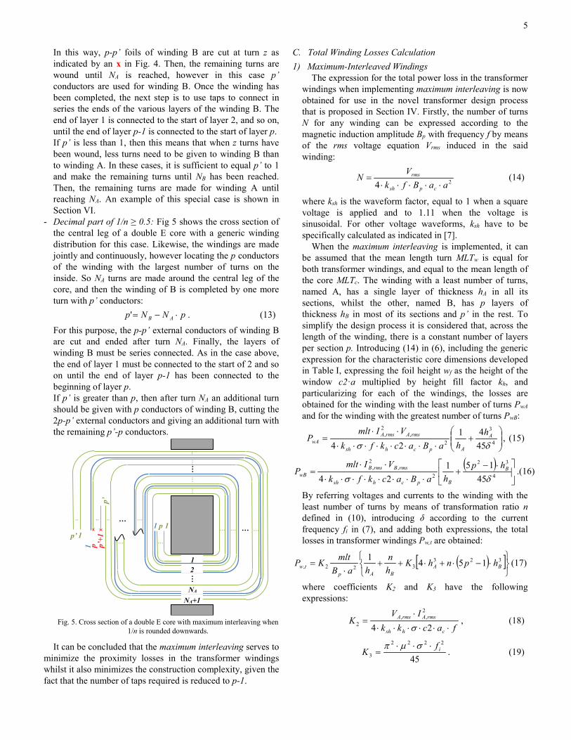
In this way, p-p’ foils of winding B are cut at turn z as indicated by an x in Fig. 4. Then, the remaining turns are wound until NA is reached, however in this case p’ conductors are used for winding B. Once the winding has been completed, the next step is to use taps to connect in series the ends of the various layers of the winding B. The end of layer 1 is connected to the start of layer 2, and so on, until the end of layer p-1 is connected to the start of layer p. If p’ is less than 1, then this means that when z turns have been wound, less turns need to be given to winding B than to winding A. In these cases, it is sufficient to equal p’ to 1 and make the remaining turns until NB has been reached. Then, the remaining turns are made for winding A until reaching NA. An example of this special case is shown in Section VI.
- Decimal part of 1/n ≥ 0.5: Fig 5 shows the cross section of the central leg of a double E core with a generic winding distribution for this case. Likewise, the windings are made jointly and continuously, however locating the p conductors of the winding with the largest number of turns on the inside. So NA turns are made around the central leg of the core, and then the winding of B is completed by one more turn with p’ conductors:
pNNp AB ⋅−=' . (13)
For this purpose, the p-p’ external conductors of winding B are cut and ended after turn NA. Finally, the layers of winding B must be series connected. As in the case above, the end of layer 1 must be connected to the start of 2 and so on until the end of layer p-1 has been connected to the beginning of layer p. If p’ is greater than p, then after turn NA an additional turn should be given with p conductors of winding B, cutting the 2p-p’ external conductors and giving an additional turn with the remaining p’-p conductors.
Fig. 5. Cross section of a double E core with maximum interleaving when
1/n is rounded downwards.
It can be concluded that the maximum interleaving serves to minimize the proximity losses in the transformer windings whilst it also minimizes the construction complexity, given the fact that the number of taps required is reduced to p-1.
C. Total Winding Losses Calculation 1) Maximum-Interleaved Windings
The expression for the total power loss in the transformer windings when implementing maximum interleaving is now obtained for use in the novel transformer design process that is proposed in Section IV. Firstly, the number of turns N for any winding can be expressed according to the magnetic induction amplitude Bp with frequency f by means of the rms voltage equation Vrms induced in the said winding:
24 aaBfkV
Ncpsh
rms
⋅⋅⋅⋅⋅= (14)
where ksh is the waveform factor, equal to 1 when a square voltage is applied and to 1.11 when the voltage is sinusoidal. For other voltage waveforms, ksh have to be specifically calculated as indicated in [7].
When the maximum interleaving is implemented, it can be assumed that the mean length turn MLTw is equal for both transformer windings, and equal to the mean length of the core MLTc. The winding with a least number of turns, named A, has a single layer of thickness hA in all its sections, whilst the other, named B, has p layers of thickness hB in most of its sections and p’ in the rest. To simplify the design process it is considered that, across the length of the winding, there is a constant number of layers per section p. Introducing (14) in (6), including the generic expression for the characteristic core dimensions developed in Table I, expressing the foil height wf as the height of the window c2·a multiplied by height fill factor kh, and particularizing for each of the windings, the losses are obtained for the winding with the least number of turns PwA and for the winding with the greatest number of turns PwB:
+
⋅⋅⋅⋅⋅⋅⋅⋅
⋅⋅= 4
3
2,
2,
4541
24 δσA
Apchsh
rmsArmsAwA
hhaBackfk
VImltP , (15)
( )
⋅−+
⋅⋅⋅⋅⋅⋅⋅⋅
⋅⋅= 4
32
2,
2,
45151
24 δσB
Bpchsh
rmsBrmsBwB
hphaBackfk
VImltP .(16)
By referring voltages and currents to the winding with the least number of turns by means of transformation ratio n defined in (10), introducing δ according to the current frequency fi in (7), and adding both expressions, the total losses in transformer windings Pw,t are obtained:
( )[ ]
⋅−⋅+⋅++⋅
= 323322, 1541
BABAp
tw hpnhKhn
haBmltKP (17)
where coefficients K2 and K3 have the following expressions:
fackk
IVK
chsh
rmsArmsA
⋅⋅⋅⋅⋅⋅
⋅=
24
2,,
2 σ, (18)
45
2222
3if
K⋅⋅⋅
=σµπ
. (19)
…
…
…
…
…
…
… …
…
…
.. 1 p 1
..
1
p’ 1
1
2
NA
NA+1
p’
p
p’+
1
…
…
..
.. …

6
As the length of the taps is negligible and the number of taps is minimum, the increase in losses due to the taps in maximum-interleaved windings can be disregarded.
2) Non-Interleaved Windings As explained above, sometimes a non-interleaved winding distribution is preferred. In this case, the number of layers per section p is equal to the number of turns of the winding N. Thus, particularizing (6):
( )
⋅⋅−⋅
+⋅
⋅⋅= 4
322
45151
δσhN
hwINMLT
Pf
rmsww . (20)
Furthermore, the mean length turns of the different windings are no longer equal. For the case of two windings wound around the central leg of a shell type core, the winding A and winding B mean length turns, MLTA and MLTB respectively, can be approximated as:
( ) accamltMLT AA ⋅++=⋅= 1312 , (21)
( ) accamltMLT BB ⋅++⋅=⋅= 13132 . (22)
Introducing (14) in (20), including the generic expression for the characteristic core dimensions developed in Table I and in (21) and (22), particularizing for each of the windings, and following a similar procedure to the one indicated in the section above, the total losses in non-interleaved transformer windings are obtained:
( )
⋅+⋅
⋅+
⋅⋅+⋅−
⋅+
⋅=
nhmlt
hmltaB
K
hmltnhmltKh
nmlth
mltaB
KP
BBAA
p
BBAAB
B
A
A
ptw
33
634
3332
2,
where coefficient K4 is:
33362
2,
3,
222
4 223 fackk
IVfK
chsh
rmsArmsAi
⋅⋅⋅⋅⋅⋅
⋅⋅⋅⋅⋅=
σµπ. (24)
If the waveform is not sinusoidal, and both for fully interleaved and for non-interleaved windings, then Pw,t can be calculated as the sum of the losses due to each of the current harmonics Pw,j [29]:
∑ == max
1 ,,n
j jwtw PP (25)
where nmax is the greatest harmonic considered. For each harmonic, the harmonic rms current IA,rms,j and frequency fi,j need to be introduced in coefficients K2, K3, and K4.
IV. TRANSFORMER DESIGN METHODOLOGY For a design to be feasible, two requirements must be met.
Firstly, the windings must fit into the magnetic core window. As the foils fully take the core height up, this requirement named the geometric limit in this paper, turns into an inequality expressing that the total winding width needs to be lower than the core width c1·a (Fig. 1) as follows: ackhNhN wBBAA ⋅≤+⋅+⋅ 1 (26)
where kw represents the loss of available space due to both the coil former and the insulations between turns of the same winding and between windings. By particularizing this
inequality for maximum interleaving, referring the number of turns for winding B to winding A, and replacing the number of turns for winding A by its expression in (14), the geometric limit can be expressed as follows:
017625 ≤⋅−+
++⋅
acKKn
hh
aBK B
Ap
(27)
where coefficient K5 has the following expression:
csh
rmsA
afkV
K⋅⋅⋅
=4
,5 . (28)
Coefficients K6 and K7 model the thickness of the electrical insulation. Thus, they are a function of the type of interleaving implemented. For maximum interleaving, K7 is equal to the coil former thickness kcf and K6 is: ( ) BAB gpgK ⋅−+⋅= 126 (29)
where gAB is the insulation thickness between windings A and B and gB is the thickness of the insulation between the turns of winding B. For non-interleaved windings, K7 is equal to the sum of kcf and gAB and K6 is:
n
ggK BA +=6 (30)
where gA is the thickness of the insulation between the turns of winding A.
The second requirement, named thermal criterion, is that the transformer must be able to transfer the heat produced by its total losses Pt to the environment with a temperature rise Δτ equal to or less than the maximum allowable rise Δτmax: maxτ∆τ∆ ≤=⋅ tth PR (31)
where Pt is obtained by adding the core loss Pc in (3) to the total winding loss given by (17) for maximum-interleaved and (23) for non-interleaved windings.
Furthermore, the transformer design needs to deal with two contradictory design criteria, which are minimum volume and maximum efficiency. For the power range studied in this paper, natural ventilation is adopted as a good trade-off between these two design criteria, given the fact that its relatively low dissipation capacity ensures high efficiencies [30], [31]. Consequently, minimizing the transformer volume is considered to be a priority criterion in the free-cooled transformer design process. In this design process, the thermal rise is pre-set to 50 °C and, thus, the empirical expression for thermal resistance in (9) is applicable. As will be shown below, this expression also offers good results for different temperature rises typical of design processes. If the empirical expression of the thermal resistance in (9) is introduced in the thermal criterion in (31), the volume of the core can be expressed as:
92.1
max
92.13 046.0
τ∆t
c
Pav
⋅≥⋅ . (32)
Two conclusions can be drawn from (32). Firstly, in order to minimize the core volume, the temperature increase must be maximized and, consequently, the thermal limit must be converted to an equality. Secondly, by minimizing the total
(23)
7
losses, the transformer core volume is minimized to give an optimal design. Consequently, the design problem becomes a non-linear optimization problem in which the function of total losses is minimized, subject to the equality imposed by the thermal criterion and the geometric limit:
( )( )inequalitygeometricackhNhNs.t.
equalitythermalPRs.t.
P
wBBAA
tth
t
⋅≤+⋅+⋅
=⋅
1
min
maxτ∆
As can be seen, the resolution of (33) is complicated due to the considerable number of variables involved and the strong non-linear nature of the problem. However, as the range of soft magnetic materials on the market is limited, there are few possible values for Cm, x, y and Bsat. Furthermore, shape coefficients c1, c2 and c3 of the two high-power core shapes are closely delimited. Therefore, the solution proposed consists in covering the ranges of all the possible values for these coefficients and solving (33) with respect to the following four design parameters: dimensional factor a, magnetic induction amplitude Bp, and primary and secondary foil thicknesses hp and hs, which are equivalent to hA and hB, respectively, for a step-up transformer and to hB and hA for a step-down transformer.
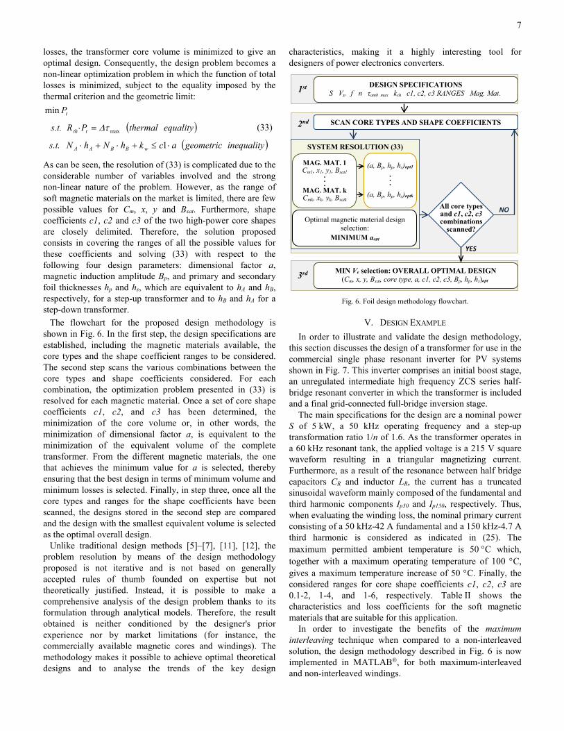
The flowchart for the proposed design methodology is shown in Fig. 6. In the first step, the design specifications are established, including the magnetic materials available, the core types and the shape coefficient ranges to be considered. The second step scans the various combinations between the core types and shape coefficients considered. For each combination, the optimization problem presented in (33) is resolved for each magnetic material. Once a set of core shape coefficients c1, c2, and c3 has been determined, the minimization of the core volume or, in other words, the minimization of dimensional factor a, is equivalent to the minimization of the equivalent volume of the complete transformer. From the different magnetic materials, the one that achieves the minimum value for a is selected, thereby ensuring that the best design in terms of minimum volume and minimum losses is selected. Finally, in step three, once all the core types and ranges for the shape coefficients have been scanned, the designs stored in the second step are compared and the design with the smallest equivalent volume is selected as the optimal overall design.
Unlike traditional design methods [5]–[7], [11], [12], the problem resolution by means of the design methodology proposed is not iterative and is not based on generally accepted rules of thumb founded on expertise but not theoretically justified. Instead, it is possible to make a comprehensive analysis of the design problem thanks to its formulation through analytical models. Therefore, the result obtained is neither conditioned by the designer's prior experience nor by market limitations (for instance, the commercially available magnetic cores and windings). The methodology makes it possible to achieve optimal theoretical designs and to analyse the trends of the key design
characteristics, making it a highly interesting tool for designers of power electronics converters.
Fig. 6. Foil design methodology flowchart.
V. DESIGN EXAMPLE In order to illustrate and validate the design methodology,
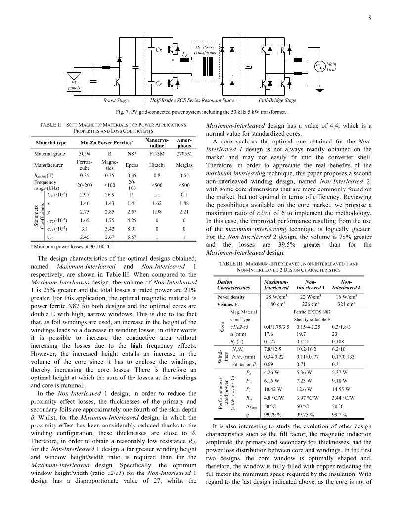
this section discusses the design of a transformer for use in the commercial single phase resonant inverter for PV systems shown in Fig. 7. This inverter comprises an initial boost stage, an unregulated intermediate high frequency ZCS series half-bridge resonant converter in which the transformer is included and a final grid-connected full-bridge inversion stage.
The main specifications for the design are a nominal power S of 5 kW, a 50 kHz operating frequency and a step-up transformation ratio 1/n of 1.6. As the transformer operates in a 60 kHz resonant tank, the applied voltage is a 215 V square waveform resulting in a triangular magnetizing current. Furthermore, as a result of the resonance between half bridge capacitors CR and inductor LR, the current has a truncated sinusoidal waveform mainly composed of the fundamental and third harmonic components Ip50 and Ip150, respectively. Thus, when evaluating the winding loss, the nominal primary current consisting of a 50 kHz-42 A fundamental and a 150 kHz-4.7 A third harmonic is considered as indicated in (25). The maximum permitted ambient temperature is 50 °C which, together with a maximum operating temperature of 100 °C, gives a maximum temperature increase of 50 °C. Finally, the considered ranges for core shape coefficients c1, c2, c3 are 0.1-2, 1-4, and 1-6, respectively. Table II shows the characteristics and loss coefficients for the soft magnetic materials that are suitable for this application.
In order to investigate the benefits of the maximum interleaving technique when compared to a non-interleaved solution, the design methodology described in Fig. 6 is now implemented in MATLAB®, for both maximum-interleaved and non-interleaved windings.
SYSTEM RESOLUTION (33)
SCAN CORE TYPES AND SHAPE COEFFICIENTS
YES
MIN Ve selection: OVERALL OPTIMAL DESIGN (Cm, x, y, Bsat, core type, a, c1, c2, c3, Bp, hp, hs)opt
NO
DESIGN SPECIFICATIONS S Vp f n τamb_max ksh c1, c2, c3 RANGES Mag. Mat.
Optimal magnetic material design selection:
MINIMUM aopt
(a, Bp, hp, hs)opt1 . . .
(a, Bp, hp, hs)optk
MAG. MAT. 1 Cm1, x1, y1, Bsat1 . . . MAG. MAT. k Cmk, xk, yk, Bsatk
All core types and c1, c2, c3 combinations
scanned?
1st
3rd
2nd (33)
8
Fig. 7. PV grid-connected power system including the 50 kHz 5 kW transformer.
The design characteristics of the optimal designs obtained, named Maximum-Interleaved and Non-Interleaved 1 respectively, are shown in Table III. When compared to the Maximum-Interleaved design, the volume of Non-Interleaved 1 is 25% greater and the total losses at rated power are 21% greater. For this application, the optimal magnetic material is power ferrite N87 for both designs and the optimal cores are double E with high, narrow windows. This is due to the fact that, as foil windings are used, an increase in the height of the windings leads to a decrease in winding losses, in other words it is possible to increase the conductive area without increasing the losses due to the high frequency effects. However, the increased height entails an increase in the volume of the core since it has to enclose the windings, thereby increasing the core losses. There is therefore an optimal height at which the sum of the losses at the windings and core is minimal.
In the Non-Interleaved 1 design, in order to reduce the proximity effect losses, the thicknesses of the primary and secondary foils are approximately one fourth of the skin depth δ. Whilst, for the Maximum-Interleaved design, in which the proximity effect has been considerably reduced thanks to the winding configuration, these thicknesses are close to δ. Therefore, in order to obtain a reasonably low resistance Rdc for the Non-Interleaved 1 design a far greater winding height and window height/width ratio is required than for the Maximum-Interleaved design. Specifically, the optimum window height/width (ratio c2/c1) for the Non-Interleaved 1 design has a disproportionate value of 27, whilst the
Maximum-Interleaved design has a value of 4.4, which is a normal value for standardized cores.
A core such as the optimal one obtained for the Non-Interleaved 1 design is not always readily obtained on the market and may not easily fit into the converter shell. Therefore, in order to appreciate the real benefits of the maximum interleaving technique, this paper proposes a second non-interleaved winding design, named Non-Interleaved 2, with some core dimensions that are more commonly found on the market, but not optimal in terms of efficiency. Reviewing the possibilities available on the core market, we propose a maximum ratio of c2/c1 of 6 to implement the methodology. In this case, the improved performance resulting from the use of the maximum interleaving technique is logically greater. For the Non-Interleaved 2 design, the volume is 78% greater and the losses are 39.5% greater than for the Maximum-Interleaved design.
It is also interesting to study the evolution of other design
characteristics such as the fill factor, the magnetic induction amplitude, the primary and secondary foil thicknesses, and the power loss distribution between core and windings. In the first two designs, the core window is optimally shaped and, therefore, the window is fully filled with copper reflecting the fill factor the minimum space required by the insulation. With regard to the last design indicated above, as the core is not of
PV panels
HF Power Transformer
Main Grid
Boost Stage Full-Bridge Stage
CR
CR
LR
Half-Bridge ZCS Series Resonant Stage
TABLE III MAXIMUM-INTERLEAVED, NON-INTERLEAVED 1 AND NON-INTERLEAVED 2 DESIGN CHARACTERISTICS
Design Characteristics
Maximum-Interleaved
Non-Interleaved 1
Non-Interleaved 2
Power density 28 W/cm3 22 W/cm3 16 W/cm3 Volume, Ve 180 cm3 226 cm3 321 cm3
Cor
e
Mag. Material Ferrite EPCOS N87 Core Type Shell type double E
c1/c2/c3 0.4/1.75/3.5 0.15/4/2.25 0.3/1.8/3 a (mm) 17.6 19.7 23 Bp (T) 0.127 0.121 0.108
Win
d-in
gs Np/Ns 7.8/12.5 10.2/16.2 6.2/10
hp/hs (mm) 0.34/0.22 0.11/0.077 0.17/0.133 Fill factor, β 0.69 0.71 0.31
Perfo
rman
ce a
t ra
ted
pow
er
(5 k
W, τ
amb 5
0 °C
)
Pc 4.26 W 5.36 W 5.37 W
Pw 6.16 W 7.23 W 9.18 W Pt 10.42 W 12.6 W 14.55 W Rth 4.8 °C/W 3.97 °C/W 3.44 °C/W Δτmax 50 °C 50 °C 50 °C η 99.79 % 99.75 % 99.7 %
TABLE II SOFT MAGNETIC MATERIALS FOR POWER APPLICATIONS: PROPERTIES AND LOSS COEFFICIENTS
Material type Mn-Zn Power Ferritesa Nanocrys-talline
Amor-phous
Material grade 3C94 R N87 FT-3M 2705M
Manufacturer Ferrox-cube
Magne-tics Epcos Hitachi Metglas
Bsat100 (T) 0.35 0.35 0.35 0.8 0.55 Frequency range (kHz) 20-200 <100 20-
100 <500 <500
Stei
nmet
z C
oeffi
cien
ts
Cm (∙10-4) 23.7 26.9 19 1.1 0.1 x 1.46 1.43 1.41 1.62 1.88 y 2.75 2.85 2.57 1.98 2.21 cT2 (·10-4) 1.65 1.75 4.25 0 0 cT1 (∙10-2) 3.1 3.42 8.91 0 0 cT0 2.45 2.67 5.67 1 1
a Minimum power losses at 90-100 °C

9
an optimum size, the window is not completely filled with copper. A greater fill, by increasing the foil thickness or the number of turns, would only lead to an increase in total losses.
For the three designs, the magnetic induction amplitude is much lower than Bsat, as is usual in free-cooled power applications [12], [13], and the primary and secondary thicknesses are different. In the Maximum-Interleaved design, as the primary winding only has one turn per section, it is not surprising that its thickness is close to the skin depth δ. In the secondary winding, as there are two turns per section, the proximity effect is greater and, therefore, its thickness is less than δ. According to [29], for this application, the optimal thicknesses would be hp=1.27δ and hs=0.97δ. In actual fact, these values would be optimal if only the winding loss is taken into account. However, when the whole transformer is sized, the foil thickness affects the window width required and, therefore, the core volume, having a direct impact on its losses and on the total transformer volume. It is, therefore, logical that the foil thicknesses for the optimal transformer are less than the optimal values determined by [29].
The goodness of the approximation carried out for the calculation of the winding loss in (6) is now assessed. It can be seen that, for the first harmonic, the winding thicknesses comply with the range for which the approximation was carried out, h≤δ50k. However, when evaluating the losses resulting from the third current harmonic, the following is obtained: hp=1.76δ150k and hs=1.14δ150k. Therefore, a precise calculation of the losses resulting from this harmonic is now made and the results compared with the approximated calculation. For the third harmonic, the exact losses for the primary and secondary are 0.14 W in both cases, whilst the value obtained with the approximation are 0.16 and 0.14 respectively. As previously indicated, the approximation overestimates the losses when the thickness exceeds the skin depth, so the design does not lose its validity.
With regard to the power loss distribution, an optimal ratio between magnetic and copper losses is sometimes proposed to minimize the total losses [12]–[14]. This optimal ratio is derived from a theoretical development in which the total losses are minimized with respect to only one design variable, being the number of turns in [14], or the equivalent magnetic induction amplitude in [12] and [13]. Both cases give the same optimal ratio, equal to 2/y, which is 0.78 for the N87 ferrite used in this case. In the Maximum-Interleaved and the Non-Interleaved 1 designs, the optimal ratios to obtain minimum losses are 0.7 and 0.74, respectively, both very close, but not equal to the conventional optimal ratio. The fact that this conventional ratio does not achieve the potential minimum losses is because the influence of only one design parameter is taken into account and, besides, no account is taken of the high frequency effects on the winding loss, which are also affected by the design parameters. In this paper, account is taken of the effects of high frequency on the windings and also the interdependencies existing between the various design parameters.
VI. PROTOTYPE ASSEMBLY AND EXPERIMENTAL VALIDATION After demonstrating the superior performance of the
maximum interleaving transformer design in theory, in this section a prototype is constructed and then experimentally validated. As shown in Table III, the analytical design methodology leads to a non-integer number of turns, which is difficult to implement in practice. Furthermore, the core and the foil conductor thicknesses must be adapted to commercially available, reasonably priced products. Thus, the optimal design is now converted into a commercial one, with the characteristics shown in Table IV. As it is shown, the optimal design can be easily adapted to the commercial environment, although, obviously, the exact characteristics of the theoretical design cannot be reproduced.
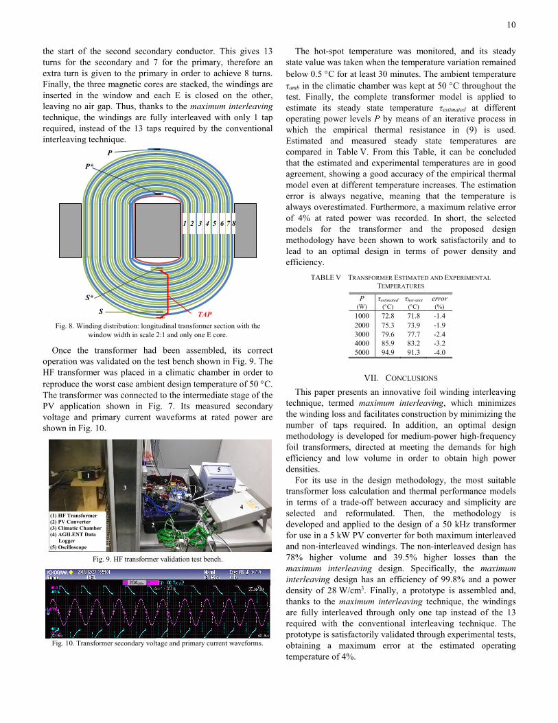
The transformer assembly process, in which the proposed maximum interleaving technique is implemented, is described below. Fig. 8 shows a longitudinal section of the transformer in which the width of the window is represented with a scale of 2:1 and only one core drawn. Firstly, as 1/n is equal to 1.6, a primary conductor must be wound together with two secondary conductors on the coil former, i.e. p=2. To do so, three conductors are cut, one for the primary with a thickness of 0.406 mm and a length equal to 8 times the MLTc, and two secondary ones with a thickness of 0.203 mm and a length that is 7 times the MLTc. Terminal P* is soldered to the start of the primary conductor, terminal S* is soldered to the start of the first secondary conductor, and the terminal required for the tapping is soldered to the second secondary conductor. The conductors are insulated from each other by means of adhesive tape comprising a polyester film and thermoset synthetic adhesive, called TECROLL. As the decimal part of 1/n is greater than 0.5, they are simultaneously wound with the primary conductor located in the interior, until 6 complete turns have been made, i.e. z=floor(13/2)=6.
Secondly, as p’ is less than 1, the outmost conductor of the
secondary is cut and terminal S is soldered to its end, i.e. p’=1 and the number of conductors to be cut p-p’=1. Then a further turn is made with the primary conductor and with the remaining secondary conductor. At this point, the end of the tap is soldered to the end of this secondary conductor. This tap series connects the end of the first secondary conductor with
TAP
TABLE IV DESIGN ADAPTED TO THE COMMERCIAL ENVIRONMENT
Equivalent Volume: 250 cm3
Efficiency (5kW): 99.8%
Power density: 20 W/cm3
Magnetic core: Windings: • Material: Ferrite R type • Foil thickness: hp/hs (mm) • Core shape: 3xEE55/28/21 0.406/0.203 • Dimensions: • Turn numbers: Np/Ns
c1/c2/c3 0.6/2.15/3.66 8/13 a 0.0172 m • Fill factor, β: 0.51
Flux density, Bp: 0.124T Operating characteristics at 5 kW:
Pc 4.44 W Pw 5.97 W Pt 10.41 W Rth 4.47 K/W Δτmax 45 °C
10
the start of the second secondary conductor. This gives 13 turns for the secondary and 7 for the primary, therefore an extra turn is given to the primary in order to achieve 8 turns. Finally, the three magnetic cores are stacked, the windings are inserted in the window and each E is closed on the other, leaving no air gap. Thus, thanks to the maximum interleaving technique, the windings are fully interleaved with only 1 tap required, instead of the 13 taps required by the conventional interleaving technique.
Fig. 8. Winding distribution: longitudinal transformer section with the
window width in scale 2:1 and only one E core.
Once the transformer had been assembled, its correct operation was validated on the test bench shown in Fig. 9. The HF transformer was placed in a climatic chamber in order to reproduce the worst case ambient design temperature of 50 °C. The transformer was connected to the intermediate stage of the PV application shown in Fig. 7. Its measured secondary voltage and primary current waveforms at rated power are shown in Fig. 10.
Fig. 9. HF transformer validation test bench.
Fig. 10. Transformer secondary voltage and primary current waveforms.
The hot-spot temperature was monitored, and its steady state value was taken when the temperature variation remained below 0.5 °C for at least 30 minutes. The ambient temperature τamb in the climatic chamber was kept at 50 °C throughout the test. Finally, the complete transformer model is applied to estimate its steady state temperature τestimated at different operating power levels P by means of an iterative process in which the empirical thermal resistance in (9) is used. Estimated and measured steady state temperatures are compared in Table V. From this Table, it can be concluded that the estimated and experimental temperatures are in good agreement, showing a good accuracy of the empirical thermal model even at different temperature increases. The estimation error is always negative, meaning that the temperature is always overestimated. Furthermore, a maximum relative error of 4% at rated power was recorded. In short, the selected models for the transformer and the proposed design methodology have been shown to work satisfactorily and to lead to an optimal design in terms of power density and efficiency.
VII. CONCLUSIONS This paper presents an innovative foil winding interleaving
technique, termed maximum interleaving, which minimizes the winding loss and facilitates construction by minimizing the number of taps required. In addition, an optimal design methodology is developed for medium-power high-frequency foil transformers, directed at meeting the demands for high efficiency and low volume in order to obtain high power densities.
For its use in the design methodology, the most suitable transformer loss calculation and thermal performance models in terms of a trade-off between accuracy and simplicity are selected and reformulated. Then, the methodology is developed and applied to the design of a 50 kHz transformer for use in a 5 kW PV converter for both maximum interleaved and non-interleaved windings. The non-interleaved design has 78% higher volume and 39.5% higher losses than the maximum interleaving design. Specifically, the maximum interleaving design has an efficiency of 99.8% and a power density of 28 W/cm3. Finally, a prototype is assembled and, thanks to the maximum interleaving technique, the windings are fully interleaved through only one tap instead of the 13 required with the conventional interleaving technique. The prototype is satisfactorily validated through experimental tests, obtaining a maximum error at the estimated operating temperature of 4%.
TABLE V TRANSFORMER ESTIMATED AND EXPERIMENTAL TEMPERATURES
P τestimated τhot-spot error (W) (°C) (°C) (%)
1000 72.8 71.8 -1.4 2000 75.3 73.9 -1.9 3000 79.6 77.7 -2.4 4000 85.9 83.2 -3.2 5000 94.9 91.3 -4.0
20A/div
1
3
2
4
5
(1) HF Transformer (2) PV Converter (3) Climatic Chamber (4) AGILENT Data Logger (5) Oscilloscope
1 2 3 4 5 6 7 8
S
P
P*
TAP
S*

11
ACKNOWLEDGMENT The authors gratefully acknowledge INGETEAM POWER
TECHNOLOGY for their financial and permanent support, and Centro Politécnico Salesianos Pamplona for their support in the prototype construction process.
REFERENCES [1] J. Biela, U. Badstuebner, and J. W. Kolar, “DC – DC Converter for
Telecom Applications,” IEEE Trans. Power Electron., vol. 24, no. 7, pp. 1701–1710, Jul. 2009.
[2] H.-S. Kim, M.-H. Ryu, J.-W. Baek, and J.-H. Jung, “High-Efficiency Isolated Bidirectional AC–DC Converter for a DC Distribution System,” IEEE Trans. Power Electron., vol. 28, no. 4, pp. 1642–1654, Apr. 2013.
[3] J. Everts, F. Krismer, J. Van Den Keybus, J. Driesen, S. Member, and J. W. Kolar, “Optimal ZVS Modulation of Single-Phase Single-Stage Bidirectional DAB AC – DC Converters,” IEEE Trans. Power Electron., vol. 29, no. 8, pp. 3954–3970, Aug. 2014.
[4] T. Besselmann, A. Mester, D. Dujic, and S. Member, “Power Electronic Traction Transformer : Efficiency Improvements Under Light-Load Conditions,” IEEE Trans. Power Electron., vol. 29, no. 8, pp. 3971–3981, Aug. 2014.
[5] N. Mohan, T. M. Undeland, and W. P. Robbins, “Power Electronics: Converters, Applications, and Design,” 3rd ed., New York: John Wiley & Sons, 2003, ch. 30.
[6] M. K. Kazimierczuk, “High-Frequency Magnetic Components,” 2nd ed., Chischester, U. K.: John Wiley & Sons, 2014, ch. 5 and 11.
[7] W. G. Hurley and W. H. Wölfle, “Transformers and Inductors for Power Electronics: Theory, Design and Applications,” 1st ed., Chischester, U. K.: John Wiley & Sons, 2013, ch. 3-6.
[8] M. Pavlovsky, S. W. H. de Haan, and J. A. Ferreira, “Partial Interleaving: A Method to Reduce High Frequency Losses and to Tune the Leakage Inductance in High Current, High Frequency Transformer Foil Windings,” in Proc. IEEE PESC, 2005, pp. 1540–1547.
[9] D. C. Pentz, “Overview of helical foil winding design for planar magnetic components,” 2013 IEEE Int. Conf. Ind. Technol., 2013, pp. 628–632.
[10] Z. Ouyang and M. A. E. Andersen, “Overview of Planar Magnetic Technology — Fundamental Properties,” IEEE Trans. Power Electron., vol. 29, no. 9, pp. 4888–4900, Sep. 2014.
[11] C. W. T. McLyman, “Transformer and Inductor design Handbook,” 3rd ed., New York: Marcel Dekker, 2004, ch. 5-7.
[12] R. Petkov, “Optimum design of a high-power, high-frequency transformer,” IEEE Trans. Power Electron., vol. 11, no. 1, pp. 33–42, Jan. 1996.
[13] W. G. Hurley, W. H. W, and J. G. Breslin, “Optimized Transformer Design: Inclusive of High-Frequency Effects,” IEEE Trans. Power Electron., vol. 13, no. 4, pp. 651–659, Jul. 1998.
[14] N. R. Coonrod, “Transfonner Computer Design Aid for Higher Frequency Switching Power Supplies,” IEEE Trans. Power Electron., vol. PE-1, no. 4, pp. 248–256, Oct. 1986.
[15] C. P. Steinmetz, “On the law of hysteresis,” Proc. IEE, vol. 72, no. 2, pp. 197–221, Feb. 1984.
[16] S. A. Mulder, “Fit formulae for power loss in ferrites and their use in transformer design,” in Proc. PCIM, 1993, pp. 345–359.
[17] K. Venkatachalam, C. R. Sullivan, T. Abdallah, and H. Tacca, “Accurate prediction of ferrite core loss with nonsinusoidal waveforms using only Steinmetz parameters,” in Proc. IEEE COMPEL, 2002, pp. 36–41.
[18] J. Mühlethaler, J. Biela, J. W. Kolar, and A. Ecklebe, “Improved Core-Loss Calculation for Magnetic Components Employed in Power Electronic Systems,” IEEE Trans. Power Electron., vol. 27, no. 2, pp. 964–973, Feb. 2012.
[19] I. Villar, U. Viscarret, I. Etxeberria-Otadui, and a. Rufer, “Global Loss Evaluation Methods for Nonsinusoidally Fed Medium-Frequency Power Transformers,” IEEE Trans. Ind. Electron., vol. 56, no. 10, pp. 4132–4140, Oct. 2009.
[20] T. Hatakeyama and K. Onda, “Core Loss Estimation of Various Materials Magnetized With the Symmetrical / Asymmetrical Rectangular Voltage,” IEEE Trans. Power Electron., vol. 29, no. 12, pp. 6628–6635, Dec. 2014.
[21] P. L. Dowell, “Effects of eddy currents in transformer windings,” Proc. Inst. Electr. Eng., vol. 113, no. 8, pp. 1387–1394, Aug. 1966.
[22] J.-P. Vandelac and P. D. Ziogas, “A Novel Approach for Minimizing High-Frequency Transformer Copper Losses,” IEEE Trans. Power Electron., vol. 3, no. 3, pp. 266–276, Jul. 1988.
[23] M. A. Bahmani, S. Member, and H. Ortega, “An Accurate Pseudoempirical Model of Winding Loss Calculation in HF Foil and Round Conductors in Switchmode Magnetics,” IEEE Trans. Power Electron., vol. 29, no. 8, pp. 4231–4246, Aug. 2014.
[24] E. C. Snelling, Soft Ferrites: Properties and Applications, 1st ed. London, U. K.: Iliffe Books Ltd, 1969, ch. 11.
[25] Ferroxcube Components, “Application note on the design of low profile high frequency transformers,” 1990.
[26] EPCOS A. G., “Application notes. Ferrites and accessories,” 2006. [27] F. Musavi, M. Craciun, D. S. Gautam, W. Eberle, and W. G. Dunford,
“An LLC Resonant DC – DC Converter for Wide Output Voltage Range Battery Charging Applications,” IEEE Trans. Power Electron., vol. 28, no. 12, pp. 5437–5445, Dec. 2013.
[28] J.-H. Jung, “Bifilar Winding of a Center-Tapped Transformer Including Integrated Resonant Inductance for LLC Resonant Converters,” IEEE Trans. Power Electron., vol. 28, no. 2, pp. 615–620, Feb. 2013.
[29] W. G. Hurley, E. Gath, and J. G. Breslin, “Optimizing the AC Resistance of Multilayer Transformer Windings with Arbitrary Current Waveforms,” IEEE Trans. Power Electron., vol. 15, no. 2, pp. 369–376, Mar. 2000.
[30] M. Pavlovsky, S. W. H. de Haan, and J. A. Ferreira, “Reaching High Power Density in Multikilowatt DC–DC Converters With Galvanic Isolation,” IEEE Trans. Power Electron., vol. 24, no. 3, pp. 603–612, Mar. 2009.
[31] W. G. Odendaal and J. A. Ferreira, “A thermal model for high-frequency magnetic components,” IEEE Trans. Ind. Appl., vol. 35, no. 4, pp. 924–931, Jul./Aug. 1999.
Ernesto L. Barrios (S’12) was born in Pamplona, Spain, in 1988. He received the B.Sc. and M.Sc. degrees (with honors) in Electrical Engineering from the Public University of Navarre, Pamplona, Spain, in 2009 and 2012, respectively. In 2011, he joined the Research Group in Electrical Engineering, Power Electronics and Renewable Energy (INGEPER) of the Public University of Navarre, where he is currently pursuing his Ph.D. His main research interests
include high frequency magnetics, wide bandgap power semiconductor devices and power converters for renewable energies, particularly for photovoltaics and fuel cells.
Andoni Urtasun (S’11) was born in Pamplona, Spain, in 1987. He received the M.Sc. degree in electrical engineering from the Public University of Navarre, Pamplona, Spain, and from the Institut National Polytechnique de Toulouse, Toulouse, France, both in 2010.
In 2010, he joined the Electrical Engineering, Power Electronics and Renewable Energy research group, Public University of Navarre, where he is currently pursuing his Ph.D. His research interests
include power electronics and renewable energies.
Alfredo Ursúa (M’04) received the B.Sc. and M.Sc. degrees, both with honors, in Electrical Engineering in 2001 and 2004, respectively, and the Ph.D. degree in Electrical Engineering in 2010, all from the Public University of Navarre, Spain. In 2002 he joined the Department of Electrical and Electronic Engineering at the Public University of Navarre, first as a researcher and since 2010 as Associate Professor. He is Vice Dean of the Technical School for Industrial Engineering and Telecommunications and member of the Steering
Committee of the university Chair for Renewable Energies. He has been involved in several research projects both with private and public funding, and mainly related to renewable energy systems, hydrogen technologies, power electronics and electric microgrids. He has also co-authored more than 50 journal papers and conference contributions, and holds 2 patents.

12
Dr. Ursúa is member of the IEEE and the Spanish Hydrogen Association. Luis Marroyo (M’04) received the M.Sc. degree in electrical engineering in 1993 from the University of Toulouse, France, and the Ph.D. degree in electrical engineering in 1997 from the Public University of Navarre (UPNa), Spain, and in 1999 from the LEEI-ENSEEIHT INP Toulouse, France. From 1993 to 1998, he was Assistant Professor at the Department of Electrical and Electronic Engineering of the UPNa, where he currently works as Associate Professor, since 1998. He is the head of
the Electrical Engineering, Power Electronics and Renewable Energy research group (INGEPER). He has been involved in more than 60 research projects mainly, in co-operation with industry, he is the co-inventor of 11 international patents and co-authored of more than 75 papers in international journals and conferences. His research interests include power electronics, grid quality and renewable energy.
Pablo Sanchis (M’03, SM’12) received the M.Sc. and Ph.D. degrees (with honors) in Electrical Engineering in 1995 and 2002, respectively, and the M.Sc. degree in Management and Business Administration in 1994, all from the Public University of Navarra, Pamplona, Spain. From 1996 to 1998, he worked as a Guest Researcher at Delft University of Technology, The Netherlands. In 1998, he joined the Department of Electrical and Electronic Engineering at the Public
University of Navarra, where he is currently Associate Professor. He is also the Head of the Chair for Renewable Energies of the university. He has been involved in more than 62 research projects mainly in co-operation with industry, and is the co-inventor of 8 patents. He has also co-authored around 40 journal papers and more than 70 conference contributions. Dr. Sanchis is member of IEEE and the Spanish Hydrogen Association. His research interests include renewable energies, power electronics, hydrogen technologies, electric grid integration and electric microgrids.