
High-Frequency Induction Heating of Al-Si-Cu-Mg aluminum ...
7
DOI: http://dx.doi.org/10.1590/1980-5373-MR-2019-0253 Materials Research. 2019; 22(5): e20190253 High-Frequency Induction Heating of Al-Si-Cu-Mg aluminum alloy in Thixoforming Saziana Samat a * , Mohd Zaidi Omar a , Intan Fadhlina Mohamed a Received: March 18, 2019; Revised: June 11, 2019; Accepted: July 27, 2019 Thixoforming is the process of shaping near net shape metal components in a semisolid state. The process consists of preparing feedstock, reheating and shaping. Reheating the billet is the most critical step in thixoforming. Induction heating requires precise temperature control to obtain globular microstructure and prevent process defects, such as insufficient heating, overheating, and electromagnetic end effect and elephant foot phenomena. Moreover, inductive heating parameters are investigated to improve the quality of thixoforming. This study investigates applied coil current and optimal coil geometry and design (i.e. height, diameter and coil turn) in high-frequency induction heating numerically and experimentally. Simulation results combined with an approximation approach method are verified via a reheating experiment. The proposed method validated via an experiment can be a practical tool for predicting temperature distribution and reheating time required for thixoforming. Keywords: Induction Heating, Aluminium alloys, Reheating, Thixoforming. *e-mail: [email protected] 1. Introduction Thixoforming is a semisolid process for producing net shape products whereas the initial feedstock is in a solid state. The process involves two stages, namely, reheating and forming 1 . Reheating the billet in a semisolid state is a particularly crucial stage in thixoforming and is mainly achieved by induction heating to obtain a uniform nondendritic microstructure 2-9 . This inductive heating system is non-contact, clean, precise and rapid in heating 7,8 . The reheating process in inductive heating system starts when an alternating electric current induces electromagnetic fields which consequently generates an eddy currents to release energy and distributes heat throughout the workpiece 9 . Although the process has been successfully applied in many industrial processes, reheating in thixoforming need to emphasize on certain system operation, parameter and coil design. An induction heating system has several restriction in achieving uniform temperature distribution; that attributed to defects from the result of insufficient heating, overheating and electromagnetic end effect over the entire cross-sectional billet area 10-12 . Research has investigated the effect of inductive heating in thixoforming via a numerical simulation or experimental method 13-15 . Kapranos et al. demonstrated a favourable agreement of experimental and calculated data concerning insulation top and bottom of the slug 16 . Jung et al. presented a numerical approach in ANSYS to solve an induction heating problem with an optimal coil design variation for a specific billet at a constant frequency 17 . These authors observed a consistent uniform temperature with a globular microstructure. Kang et al. proposed an objective function on the basis of computational techniques and a numerical simulation model 18 . Such efforts focused on enhancing computational time and contributions and producing favourable mechanical properties during the reheating process. Jiang et al. suggested a numerical simulation via conjugate gradient method 19 . These researchers found that investigations with different frequencies do not significantly affect temperature uniformity. Song et al. presented another optimisation process parameter in A319 aluminium alloy with the effect of different coil turns on the reheating process 20 . The present study determines the reheating condition of thixoforming with the magnitude of coil current using the approximation approach method and variation in coil geometry. The process of inductive heating is described and investigated numerically and experimentally. The results of the simulation are compared with the experimental test to verify the validity of the proposed method. 2. Experimental Procedure The alloy used in this study was fabricated via a conventional casting process. X-ray fluorescence (XRF) was used to determine the chemical composition of the alloy, as presented in Table 1. The alloy was subjected to a cooling slope (CS) casting processing route to prepare the suitable non dendritic feedstock for thixoforming 21-23 . a Centre for Materials Engineering and Smart Manufacturing (MERCU), Faculty of Engineering & Built Environment, Universiti Kebangsaan, Malaysia, 43600, Bangi, Malaysia
Transcript of High-Frequency Induction Heating of Al-Si-Cu-Mg aluminum ...
DOI: http://dx.doi.org/10.1590/1980-5373-MR-2019-0253Materials Research. 2019; 22(5): e20190253
High-Frequency Induction Heating of Al-Si-Cu-Mg aluminum alloy in Thixoforming
Saziana Samata* , Mohd Zaidi Omara, Intan Fadhlina Mohameda
Received: March 18, 2019; Revised: June 11, 2019; Accepted: July 27, 2019
Thixoforming is the process of shaping near net shape metal components in a semisolid state. The process consists of preparing feedstock, reheating and shaping. Reheating the billet is the most critical step in thixoforming. Induction heating requires precise temperature control to obtain globular microstructure and prevent process defects, such as insufficient heating, overheating, and electromagnetic end effect and elephant foot phenomena. Moreover, inductive heating parameters are investigated to improve the quality of thixoforming. This study investigates applied coil current and optimal coil geometry and design (i.e. height, diameter and coil turn) in high-frequency induction heating numerically and experimentally. Simulation results combined with an approximation approach method are verified via a reheating experiment. The proposed method validated via an experiment can be a practical tool for predicting temperature distribution and reheating time required for thixoforming.
Keywords: Induction Heating, Aluminium alloys, Reheating, Thixoforming.
*e-mail: [email protected]
1. Introduction
Thixoforming is a semisolid process for producing net shape products whereas the initial feedstock is in a solid state. The process involves two stages, namely, reheating and forming1. Reheating the billet in a semisolid state is a particularly crucial stage in thixoforming and is mainly achieved by induction heating to obtain a uniform nondendritic microstructure2-9. This inductive heating system is non-contact, clean, precise and rapid in heating7,8.
The reheating process in inductive heating system starts when an alternating electric current induces electromagnetic fields which consequently generates an eddy currents to release energy and distributes heat throughout the workpiece9. Although the process has been successfully applied in many industrial processes, reheating in thixoforming need to emphasize on certain system operation, parameter and coil design. An induction heating system has several restriction in achieving uniform temperature distribution; that attributed to defects from the result of insufficient heating, overheating and electromagnetic end effect over the entire cross-sectional billet area10-12.
Research has investigated the effect of inductive heating in thixoforming via a numerical simulation or experimental method13-15. Kapranos et al. demonstrated a favourable agreement of experimental and calculated data concerning insulation top and bottom of the slug16. Jung et al. presented a numerical approach in ANSYS to solve an induction heating problem with an optimal coil design variation for
a specific billet at a constant frequency17. These authors observed a consistent uniform temperature with a globular microstructure. Kang et al. proposed an objective function on the basis of computational techniques and a numerical simulation model18. Such efforts focused on enhancing computational time and contributions and producing favourable mechanical properties during the reheating process. Jiang et al. suggested a numerical simulation via conjugate gradient method19. These researchers found that investigations with different frequencies do not significantly affect temperature uniformity. Song et al. presented another optimisation process parameter in A319 aluminium alloy with the effect of different coil turns on the reheating process20.
The present study determines the reheating condition of thixoforming with the magnitude of coil current using the approximation approach method and variation in coil geometry. The process of inductive heating is described and investigated numerically and experimentally. The results of the simulation are compared with the experimental test to verify the validity of the proposed method.
2. Experimental Procedure
The alloy used in this study was fabricated via a conventional casting process. X-ray fluorescence (XRF) was used to determine the chemical composition of the alloy, as presented in Table 1. The alloy was subjected to a cooling slope (CS) casting processing route to prepare the suitable non dendritic feedstock for thixoforming21-23.
aCentre for Materials Engineering and Smart Manufacturing (MERCU), Faculty of Engineering & Built Environment, Universiti Kebangsaan, Malaysia, 43600, Bangi, Malaysia
Samat et al.2 Materials Research
Table 1. Chemical composition aluminium casting alloys, (wt%)
Alloys Si Cu Mg Fe Mn Al
Al-Si-Cu 5.67 1.92 0.32 0.32 0.12 Remainder
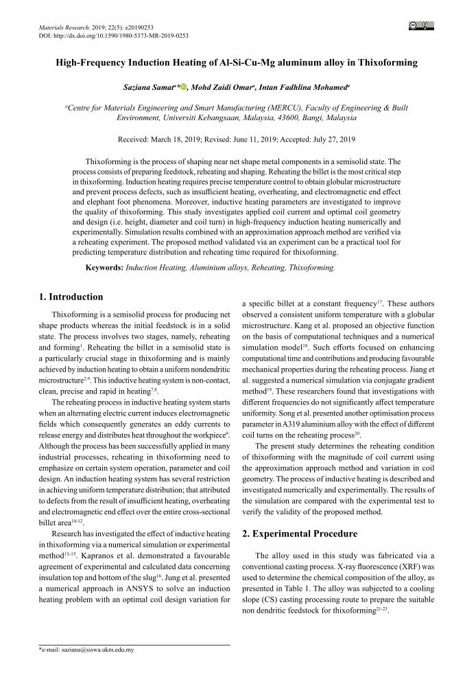
The reheating experiments were performed using an induction heating system with a high-frequency induction heating coil system (30-80 kHz, 35 kW) at semisolid temperatures (569 °C to 600 ℃). A thermocouple hole to measure the temperature was machined at a position 15 mm from the surface (marked in S) of the billet and 10 mm at the core of the slug of the billet (marked as C), as depicted in Figure 1. K-type thermocouples were inserted into the billet for monitoring and measuring the temperature. The heating time to reach the semisolid temperature was recorded to validate the simulation results.
Figure 1. Model used for simulation study
3. Numerical Analysis
3.1 Calculation of coil current using approximation approach
The reheating process of the billet works on the influence of induction machine setups, such as induction coil geometry, applied power and coil currents. The operating condition for induction heating simulation and experimental work requires applied coil currents as an input parameter for analysing the reheating process. The following methods are used in identifying the coil current of induction heating: approximation approach and equivalent circuit model24. Baker used an equivalent circuit model to design an induction coil25. The basis of an equivalent circuit model is the reduction of the induction heating coil and workpiece to their equivalent resistance and inductance. Song and Moon et al. used this approach to evaluate the effect of induction heating variable and reported favourable results in practice26. However, several difficulties include solving many equations and undergoing a lengthy iteration process.
By contrast, an approximation approach claim that this method is fast and accurate in determining coil currents. The basis of this method is using the design curve for coil
efficiency, power factor and reflected impedance of turned square. Although the curves are primarily theoretical, correction factors were based on reference data on the equivalent circuit model24.
Coil efficiency, η, works of the part of energy delivered and transferred to the coil can be defined as the ratio expressed as
,PPw
0h =
(1)
where Pw is the total power into work (including radiation), and P0[kW] is the total power at coil terminal (including coil losses). The coil power factor, cos ϕ, is expressed as
.cos KVAP
E IP
c c c
0 0z = = (2)
The coil impedance per turn squared is defined as
.NZ
I NKVA
N KVAE
c c c
c
c c
c2 2= =l
Q V (3)
From this definition, the efficiency, coil factor and coil impedance per turn squared can be obtained directly from the design curved24. Consequently, from the relationship of the coil impedance per turn squared, coil current, Ic [A], can be obtained as
.IZ
N
KVA Nc
c
cc
2
#=l
(4)
Given that the efficiency and coil current of induction heating can be calculated for the different variables directly, the effect of induction heating variable on the efficiency and coil current can be evaluated via this coil design approximation approach.
3.2 Simulation Studies
The induction coil is essential to the inductive heating system to provide the homogenous heating pattern distribution to the workpieces. Previous researcher17 thoroughly discussed the details on coil design in determining coil length. Here, an analysis of a couple of electromagnetic-thermal with induction heating coil of a given alloy in the reheating process were solved using commercial finite element software package COMSOL Multiphysics. The simulation model 2D axisymmetric and 3D geometry model of the induction heating used in the analysis are illustrated in Figure 1. The coil dimension for reheating is presented in Table 2 with

3High-Frequency Induction Heating of Al-Si-Cu-Mg aluminum alloy in Thixoforming
various coil lengths of 90, 110 and 130 mm. The coil was modelled with 6 multiturn coil copper wires of 50 mm inner diameter. Initial suitability of an optimal coil design from the simulation works was analysed and verified via experimental works of the heating process.
4. Results and Discussion
4.1 Electromagnetic field and eddy current distribution
Figure 2 plots the distribution of magnetic field intensity (A/m) and the contour of magnetic flux density (T) for the 25 mm-diameter heated billet workpiece with a coil length of 110 mm. A 2D axisymmetric model demonstrates an electromagnetic field near the coil. The maximum magnetic field intensity occurs and concentrates along the surface region area. The concentration finally causes the skin effect given an alternating magnetic field that generated the eddy current. For the magnetic flux density, the contour flows near the billet. This effect represents the magnetic vector potential between the induction coil and workpiece, whereby the high strength of the magnetic field occurs in the middle of a coil and workpiece. The appropriate gap between billet and coil creates an increasingly magnetic line via the coil.
Figure 3 displays the distribution of eddy current in the workpiece for the cases of coil lengths 90mm, 110mm and 130 mm. The effective eddy current is located from the side wall of the surface, and no current is found in the core position. A positive value represents the current density of the coil, whereas a negative value exhibits the induced current
Table 2. Dimension of various coil length used in the simulation
Billet diameter, (d)
Coil inner diameter (Di)
Heating length, lw
Coil length, H
25mm 50mm 9090mm110mm130mm
The cylindrical billet workpiece of Al-Si-Cu-Mg alloy was placed in the middle of the asymmetric induction coil cooled by water flow in an internal cooling channel. The coil and specimen were placed in the air domain. Table 3 summarises the material property values from the required data based on JmatPro software and constantly used for simulation studies. The boundary conditions used for the electromagnetic and heat transfer are listed in Table 4. Reheating was performed until 1500 s at a semisolid temperature of approximately 30% to 50% liquid fraction (569 °C to 600 ℃) and monitored at two points marked with C and S as core and surfaces, respectively, as depicted in Figure 1.
Table 3. Material Properties and constant used for the simulation
Material Property Air Aluminium Copper
Relative permeability, µ,r 1 1 1
Electrical Conductivity, σ (S/m) 0 2.44 X 10⁻⁷ 5.998 x 10⁷
Thermal conductivity, κ (W/mK) 0.026 160 400
Density, ρ (kg/m3) 1.23 2717 8700
Specific Heat, Cp(J/kgK) 1005 879 385
Constants
Convective Cooeficient, h (W/m2K) 5
Emissivity, ε 0.3
Ambient temperature (K) 300
Cooling water mass flow rate, kg/s 0.001
Table 4. Boundary condition for electromagnetic and heat transfer
Electromagnetic Heat transfer
i. Axial symmetry at r = 0ii. Magnetic insulation condition applied at air boundaries (Aφ= 0)iii. Magnetic fields on the interior boundaries n x A = 0
i. Axial symmetry at r = 0ii. Temperature Boundary condition at the air boundaries, T = T0= 293Kiii. Heat Flux at other boundaries
k nT q qradiative heat flux convective heat flux1 22
2 = +S X
k nT T T h T T0
4 4
22
fv= - + -3S Q QX VV

Samat et al.4 Materials Research
Figure 2. Electromagnetic analysis of magnetic field intensity (units:A/m), a contour of magnetic flux density (units: Tesla,T) in Aluminium alloy billet
Figure 3. Electromagnetic analysis result of induced current density (unit: A/m2) for coil length of (a) 90mm (b) 110mm (c) 130mm
in the billet workpiece. The eddy current flows in a thin skin and concentrates on the outside surface. The induced current decreases in the internal area and is attributed to a skin-depth effect. The increased current density at the surface increases with the temperature. The inside of the billet is heated via thermal conduction from the surface. However, in all cases, the minimum eddy current is located at the workpiece corner, thereby representing the end and edge heating defect
4.2 Heating pattern
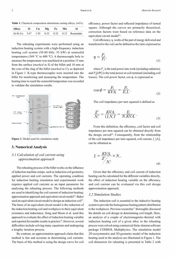
Figure 4 illustrates the temperature distribution of workpiece for the 25 mm-diameter billet with a coil length of 110 mm during reheating at the beginning of 50s, middle of 100s, 250s and end of the heating at 450 s. The workpiece heated by an eddy current and the surface billet show an elevated temperature via the heat transfer. However, the difference between the surface to the core is insignificant considering that the billet diameter is relatively small.
The electromagnetic end effect is highly pronounced in these cases with the temperature difference surface top/bottom to surface centre at 2 °C-5 °C.
Figure 5 depicts the volumetric heat generation rate (q, W/m3) profile in the workpiece for all cases. The rate is mainly the energy for the heating process, and the distribution seems similar to the eddy current distribution. The power intensity is at the maximum value at the middle portion of the outer surface of the workpiece wall. The appearance of varying heating patterns is caused directly by the difference in eddy current distribution with an increase in coil length height. The total heat generation decreases directly, thus resulting in edge effect and distortion of the electromagnetic end effect.
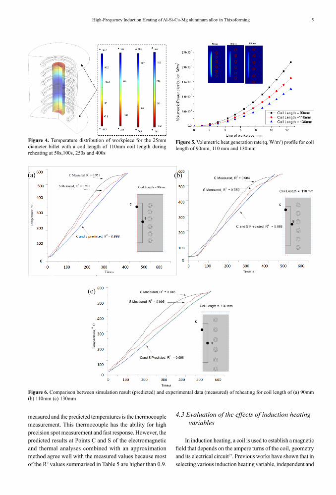
Figure 6 demonstrates the comparison confirmation between the simulation result and the experimental data for the induction coil with a length of 90mm,110mm and 130 mm. The temperature measurement variation at a different position (core and surface) along the workpiece is plotted. The reheating process stops when the temperature reaches the semisolid temperature (approximately 30%-50% liquid fraction). The temperature variation at the core and surfaces of the billet are shown as a function of time for all coil length cases. In the experiment, the temperature difference is very high (approximately 50 ℃) during the reheating process given the uncontrolled atmosphere environment. This phenomenon (called electromagnetic end effect) is a direct result of the distortion in the electromagnetic field in the area. The heating duration of the simulation and experiment are consistent for all cases at an average 385s, 450s and 525s for coil length 90mm,110mm and 13mm, respectively. The reheating time to achieved the semisolid temperature increased at long coil length.
Table 4 lists the R2 values obtained for different coil lengths between simulation and experimental temperature difference. Considering that the magnetic field depends on the current that flows to the workpiece, certain temperature differences can be generated in producing heat by Joule effect. The other possible cause of the difference between the
5High-Frequency Induction Heating of Al-Si-Cu-Mg aluminum alloy in Thixoforming
Figure 4. Temperature distribution of workpiece for the 25mm diameter billet with a coil length of 110mm coil length during reheating at 50s,100s, 250s and 400s
Figure 5. Volumetric heat generation rate (q, W/m3) profile for coil length of 90mm, 110 mm and 130mm
Figure 6. Comparison between simulation result (predicted) and experimental data (measured) of reheating for coil length of (a) 90mm (b) 110mm (c) 130mm
measured and the predicted temperatures is the thermocouple measurement. This thermocouple has the ability for high precision spot measurement and fast response. However, the predicted results at Points C and S of the electromagnetic and thermal analyses combined with an approximation method agree well with the measured values because most of the R2 values summarised in Table 5 are higher than 0.9.
4.3 Evaluation of the effects of induction heating variables
In induction heating, a coil is used to establish a magnetic field that depends on the ampere turns of the coil, geometry and its electrical circuit27. Previous works have shown that in selecting various induction heating variable, independent and

Samat et al.6 Materials Research
Figure 7. Correlation between different coil length geometry to coil efficiency and applied current
Table 5. R2-values obtained for different coil length between simulation and experimental to achieved semisolid temperature
Coil length 90mm 110mm 130mm
Point S (Measured-experiment) 0.951 0.964 0.946
Point C (Measured-experiment) 0.981 0.989 0.995
Point S and C Predicted (simulation) 0.998 0.998 0.998
dependent variables will affect the efficiency of the induction heating performance in thixoforming26.The independent variable before the thixoforming process is coil geometry (length and diameter), billet workpiece diameter, workpiece temperature, frequency and coil current. The dependent variables are electrical material relative permeability and electrical resistivity properties. These properties of the billet workpiece depend on the temperature produced by the independent variables.
Efficiency η is defined as the ratio of the induced output power in the heated part to the input power of the coil, as expressed in Equation 1. This ratio is considered an index parameter of induction heating. The efficiency parameters and temperature of the heated workpiece are evaluated without the requirement for couple electromagnetic and thermal analysis at any frequency, power and air gap between coil and billet in the inductive heating process. Through the approximation method in coil design, the critical parameter is the coil current and a strong relationship with coil efficiency, as exhibited in Figure 7. Therefore, coil efficiency is inversely proportional to coil current. This value then can be used in electromagnetic and thermal analyses as an input parameter to determine the temperature of the workpiece and the reheating duration for thixoforming.
5. Conclusion
An electromagnetic and thermal analysis combined with an approximation approach method was evaluated to analyse reheating in thixoforming. The following conclusions were obtained:
1. An approximation approach method is useful in evaluating induction heating variables on the basis of the efficiency and input coil currents.
2. The results of the electromagnetic and thermal analysis model are consistent with the measured values of the temperature and heating time required for various coil length geometry. The validity of the analysis method is confirmed well by experimental measurements.
3. The optimal reheating coil geometry and applied current are proposed to obtain a homogenous temperature distribution in thixoforming process.
6. Acknowledgements
The authors would like to thank the Universiti Kebangsaan Malaysia and the Ministry of Education (MoE) Malaysia for the financial support under research Grant DIP-2016-007.
7. References
1. Omar MZ, Atkinson H, Kapranos P. Semi-solid Metal Processing-A processing Method Under Low Flow Loads. Jurnal Kejuruteraan. 2007;19:137-46.
2. Kirkwood DH. Semi-solid metal processing. Journal of Japan Institute of Light Metals. 1995;45(6):346-54.
3. Fan Z. Semi-solid metal processing. International Materials Review. 2002;47(2):49-85.
4. Flemings MC. Behavior of Metal Alloys in the Semisolid State During dendritic solidification of castings and ingots. Metallurgical Transcation: B. 1991;22:269-93.
5. Omar MZ, Atkinson HV, Kapranos P. Thixotropy in semisolid steel slurries under rapid compression. Metallurgical Materials Transactions A: Physics Metallurgy Materials Science. 2011;42(9):2807-19.
6. Omar MZ, Palmiere EJ, Howe AA, Atkinson HV, Kapranos P. Thixoforming of a high performance HP9/4/30 steel. Materials Science and Engineering: A. 2005;395(1-2):53-61.
7. Chen TJ, Wang RQ, Ma Y, Hao Y. Effects of processing parameters on microstructure and ultimate tensile strength of thixoformed AM60B magnesium alloy. Materials Research. 2012;15(4):687-97.
8. El-Mahallawi ISE, Mahmoud TS, Gaafer AM, Mahmoud FH. Effect of Pouring Temperature and Water Cooling on the Thixotropic Semi-solid Microstructure of A319 Aluminium Cast Alloy. Materials Research. 2015;18(1):170-6.

7High-Frequency Induction Heating of Al-Si-Cu-Mg aluminum alloy in Thixoforming
9. Freitas ER, Ferracini Júnior EG, Piffer VP, Ferrante M. Microstructure, material flow and tensile properties of A356 alloy thixoformed parts. Materials Research. 2006;7(4):595-603.
10. Bayerl T, Duhovic M, Mitschang P, Bhattacharyys D. The heating of polymer composites by electromagnetic induction-A review. Composites Part A: Applied Science and Manufacturing. 2014;57:27-40.
11. Lucía O, Maussion P, Dede E, Burdío JM. Induction heating technology and its applications: Past Developments, current Technology, and future challenges. IEEE Transactions on Industrial Electronics. 2014;61(5):2509-20.
12. Rudnev V, Loveless D, Cook R, Black M. Handbook of Induction Heating. New York: Marcell Dekker, Inc.; 2003.
13. Bendada A, Zheng JCQ, Nardini N. Investigation of temperature control parameters for inductively heated semi-solid light alloys using infrared imaging and inverse heat conduction. Journal of Physics D: Applied Physics. 2004;37(7):1137-44.
14. Masserey A, Rappaz J, Rozsnyo R, Touzani R. Optimal control of an induction heating Process for thixoforming. IEEE Transactions on Magnetics. 2004;40(3):1664-71.
15. Kong X, Yang BC, Zhang ZF, Xu J. Effect of Reheating Process on Microstructure and Mechanical Property of A390 Aluminum Alloy. Materials Science Forum. 2015;817:173-9.
16. Kapranos P, Gibson RC, Kirkwood DH, Sellars CM. Melting of High Melting Point. Proc 4th Int Conf Semi-Solid Process Alloy Compos. 1996;148-52.
17. Jung HK, Kang CG. An induction heating process with coil design and solutions avoiding coarsening phenomena of Al-6 Pct Si-3 Pct Cu-0.3 Pct Mg alloy for thixoforming. Metallurgical and Materials Transactions: A. 1999;30(11):2967-77.
18. Kang CG, Seo PK, Jung HK. Numerical analysis by new proposed coil design method in induction heating process for semi-solid forming and its experimental verification with globalization evaluation. Materials Science and Engineering: A. 2003;341(1-2):121-38.
19. Jiang H, Nguyen TH, Prud'homme M. Optimal control of induction heating for semi-solid aluminum alloy forming. J Mater Process Technol. 2007;189(1-3):182-91.
20. Song N, Zhang F, He Y, Zhu Q. Experimental and Simulation Study of Microstructure of the Aluminium Alloy 319s in Induction Reheating Process. Solid State Phenomena. 2012;192-193:281-6.
21. Aziz AM, Omar MZ, Salleh MS. Evolusi Mikrostruktur Aloi A333 melalui Proses Logam Separa Pepejal. Sains Malaysiana. 2016;45(6):977-87.
22. Arif MAM, Omar MZ, Sajuri Z. Pembentukan Mikrostruktur Berbentuk Sfera dalam Keadaan Separa Pepejal Aloi Aluminium Al-4.8Si-2.8Cu-0.5Mg. Jurnal Kejuruteraan. 2018;30(2):275-80.
23. Nafisi S, Ghomashchi R. Semi-Solid Metal Processing Routes: An Overview. Canadian Mettalurgical Quaterly. 2005;44(3):289-304.
24. Simpson PG. Induction heating: coil and system design. New York: McGraw-Hill; 1960.
25. Baker RM. Design and calculation of induction heating coils'. AIEE Transactions. 1957;76(Pt 2):31-40.
26. Song MC, Moon YH. Coupled electromagnetic and thermal analysis of induction heating for the forging of marine crankshafts. Applied Thermal Engineering. 2016;98:98-109.
27. Rapoport E, Pleshivtseva Y. Optimal Control of Induction Heating Processes. New York: Taylor & Francis Group; 2007.


![Corrosion behavior of Mg-5Al based magnesium alloy with 1 ... · its protective behavior [20e23]. But, the effect of small addition amount (such as 5 wt.%) of aluminum in the Mg alloy](https://static.fdocuments.in/doc/165x107/5fa79f7bef2aec3ad13f21f6/corrosion-behavior-of-mg-5al-based-magnesium-alloy-with-1-its-protective-behavior.jpg)


