Fifth International Workshop on High Power Proton Accelerators
GILBERT: RADIATION PROBLEMS WITH HIGH ENERGY PROTON ACCELERATORS
RADIATION PROBLEMS WITH HIGH-ENERGY PROTON A C m T O R S l c
Willlau S. Gilber t
Lawrence Radiation Laboratory University of California
Berkeley, California
February 21, 1967
Abstract
We s h a l l r e s t r i c t the discussion to proton accelerators i n the multi-GeV energy range and of the alternating-gradient synchrotron type, with special a t t e n t i o n given t o the exis t ing 30-GeV and the proposed 200- t o 300-GeV nachines.
R9dia.tion problem c a n be divided i n t o two broad groups: while i t i s running and those associated w i t h the EhUt-dOWn machine. The expensa and diff i c u l t y of coping w i t h these radiat ion problems Influence the choice of design beam intensi ty ,
those produced by the accelerator
The problems while the machine i s running a r e penetration of radiat ion through the shielding, muon shielding, penetration of radiat ion through ducts ana labyrinths, skyshine, diffusion of radio- ac t ive air, and radiat ion damage to components. Some r e s u l t s of an LRt-CERN-Rutherford shielding experiment on the CERN-PS are presented,
Problems of the shut-down accelerator include induced a c t i v i t y i n the machine components and en- closure walls. These rad ia t ion f i e l d s a f f e c t uaintenance procedures and require appropriate handling too ls and shielded vehicles,
Introduction
O u r primary concern has been with the radia- t i o n problems associated with the contemplated 200- to ~ O O - G ~ V strong-focusing proton accelerators.l-3 From the radiation-protection standpoint, these machines o f f e r the advantage over the ex is t ing Brookhaven and CERN synchrotrons that , being non- existent, there is no p r i o r r e s t r i c t i o n on compon- e n t design o r operating pr inciples imposed by ex is t ing s t ructures . W e have also studled the radlat ion problems at the CEFiR-PS and BNL-AM, since these can be considered as models for the higher-energy machines, and the physical processes involved i n cascade production a re qua l i ta t ive ly the same f o r energies above about 1 2 GeV, Consill- a rab le lower-energy radiat ion invest igat ion has taken place at several proton wchines: Bevatron, Nimrod, Saturne, PPS, and ZGS. For a l l m u l t i - G e V proton and electron acceleraprs, f o r example, the Stanford Linear Accelerator, problems are qui te s i m i l a r , t he differences being related to mechanisms of beam loss and cascade de- velopment and mchine s t ructure .
most of the rad ia t ion
Both the ex is t ing CERN-PS and BNL-AGS have had continuously increasing c i rcu la t ing beams, so th& at present they routinely accelerate 4 t o 6 x
PrObns/s i n the 20- tr0 30-GeV energy range. represents some 1 to 2 kW of beam power, and the problem associated with radiat ion are already troublesome. Both machines have improvement pro- grams underway that w i l l increase t h ir circulat ing beam c m e n t s from LO to 30 times.5,% St ruc tura l modifications such as increased thickness of ear th shielding w i L 1 be required as w e l l as increased use of' external beams. The ZOO- and 300-GeV designs are capable of grea ter than 1013 protons/s o r some 500 kW of beau power. Under the worst circum- stances, radiat ion problems could make the accel- e r a t o r site uninhabitable, the accelerator inoper- able , and maintenance unreasonable. By identifying these problems f r o m the beginning of the design process, it seems feas ib le t o bui ld and maintain a high-current synchrotron ( >1013 protons/s) f o r a re la t ive ly small penalty i n capi ta l and operating cos ts as compared with a low-current synchrotron
This
(.. 10x1 protons/s).
Figure 1 is a symbolic drawing of a n acceler- ator and i t a associated radiat ion problems (see Table I), both w h i l e runnlng and when shut down
Table I. Radiation Problems
Problem Running Shut Down
1.
2,
3.
4. 5.
6 .
7.
8.
Strongly interact ing par- ticles (s.~.P.) penetrating shield xx Leakage through ducts and labyrinths xx Muons penetrating shield XX
Sky shine xx Radiation damage and heat- Xi 1%
Radioactive air, water and dust xx xx Induced a c t i v i t y i n accel- erator Induced a c t i v i t y i n tunnel walls
xx xx
Wherever primary protons are los t , all of the above-mentioned r a d h t i o n problems appear and, i n a sense, w i l l be- proportional to the number of protons interact ing i n a given region. but ion of t h i s beam lose i s a strong function of
The diatri-
© 1967 IEEE. Personal use of this material is permitted. However, permission to reprint/republish this material
for advertising or promotional purposes or for creating new collective works for resale or redistribution to servers
or lists, or to reuse any copyrighted component of this work in other works must be obtained from the IEEE.
PAC 1967

966 IEEE TRANSACTIONS ON NUCLEAR SCIENCE, JUNE 1967
t a rge t ing and has led t o primary re l iance on ex- t rac ted external proton beams i n the proposed 200- t o 300-GeV and improved CERN-PS and HNL-AGS. I n t h i s way the most formidable problems can be moved to the ta rge t s ta t ions a t the ends of the extracted beams and the rad ia t ion source Inside the acceler- ator tunnel w i l l be reduced t o t h a t f r a c t i o n of the c i rcu la t ing beam that i s not successfully ex- tracted. external ta rge t s t a t i o n s w i l l be d i f f i c u l t , but one can work on any one of them without having to tu rn off the accelerator, assuming that one has multiple external-beam capabi l i ty .
Operation and maintenance of these
The above radiat ion problems will be dis- cussed i n the framework of the 200-GeV design which has an i n i t l d c i rcu la t ing c m n t of 1.5 times 1013 pmtons/s and an ult imate in tens i ty capabi l i ty of 5 times 1013 protuns/s and a n assumed extract ion eff ic iency of 85%. More de- tailed treatment is found i n the references c i t e d above. The current p ic ture i s indicated i n the f O l l O N i U g SeCtiOn8.
Problem 1. Strongly Interact ing P a r t i c l e Shielding
Figure 2 shows e a r t h shields and machine tunnels for the CERN-PS, BNL-Am, SLAC, and 200- GeV machines, all shields adJusted to about the =me e a r t h density, For the Cm-PS and AGS accel- e ra tors , the s o l i d l i n e s are for t h e ex is t ing shields above the nontarget areas, and the dashed l i n e s a re f o r the shielding above these quiet re- gions a9ter t h e i r present improvement programs. For the W a n d the 200-GeY machines the shields a re designed f o r the ult imate intensi ty , since It i s unduly expensive t o augment shielding Later. For these latter machines the dashed l i n e s repre- s e n t the shielding above the t a r g e t o r extract ion areas. The scale of the 200-GeV machine i s such that a reduction of 6 f t i n the shield thickness (from an original. 23-ft thickness) represents a reduction i n cos t $ 3. Hence it behooves one t o reduce uncertainty here as far as possible, and 1%1l report below on a recent experiment that was carried out a t the CFRN-PS by groups from La, CERI?, and Rutherford.
Problem 2.
Leakage Through Ducts and Labyrinths
There are many types of penetrations through the shielding t h a t o f f e r a path f r o m the insiae of the tunnel t o the outside. These range from small ducts f o r conduits t o large openings f o r personnel and truck access. A s the source of radiat ion increases and the main shielding gets thicker, the leakage paths must be decreased through these penetrations. rad ia t ion transmission through ducts were made as p a r t of the experiment mentioned above and w i l l be avai lable later.
New measurements on
Problem 3. MWKI (p) Shielding
The muon is a weakly interact ing particle, and so the shielding provided f o r the S.I.P. may o r may not be sufficient to shield against them. Pions, which a r e readi ly produced i n high-energy interact ions, can decay i n t o the weakly Interact ing muon (s - t p + v ) , or, i n material, can strongly i n t e r a c t themselves. Similarly kaons can decay i n t o mmns (K + p + v ) . Moat energetic muons a re from pions and kaons tha t have decayed i n f l i g h t i n the air path between a t a r g e t and the shield Pace. Some muons r e s u l t from pion decay i n the re la t ive ly shor t range or interact ing Length of the pion i n condensed matter. muons a r e s t rongly peaked i n t h e forward, o r primary proton beam, direct ion and the ~ u o n energy spectrum extends up t o the primary proton energy.
The physical b a s i s f o r the d i f f i c u l t y i n shielding from muon8 i s tha t they are weakly in- te rac t ing and cannot lose a la rge Praction of t h e i r energy i n nuclear interactions. izat ion loss for a muon is roughly 2 MeVlg-cm-', although t h i s dE/dX i s someuhat a l te red a t d i f f e r e n t energies because of pair prodwtion and r e l a t i v i s t i c rise ef fec ts , arid through a Z depen- dence, d i f fe ren t materials have s l i g h t l y d i f fe ren t values. The length of shield necessary t o s top a muon i s rougly proportional t o i t s i n i t i a l energy. For strongly in te rac t ing par t ic les , on the o ther hand, w e speak of an exponential removal mear free path, say 130 g-cm-z. A f t e r the buildup process, t h i s means t h a t the energy le f t i n the cascade after one mean free path is one/&& that a t the beginning. As the primary proton o r pion energy increases, the apparent B/aX increases, because the observed removal mean f r e e path i s roughly constant with energy above 8 f e w hundred MeV.
I n e i t h e r case
The ion-
Figure 3 displays the difference i n the shielding of strongly interact ing p a r t i c l e s and muons. Here w e are concerned with shielding i n the straight-ahead direct ion, which is pert inent f o r the primary beam-disposal area and external- beam t a r g e t s ta t ions. For S.I.P.ts, after the usual buildup, one sees an exponential decay vs depth curve with a mean free path of some 130 g- c&. For an incident proton energy of 200-GeV, an equival n t mean free path f o r muons i s some
S.12P.t~, 3000 g-cm-2 o r approximately 6000 lb- f t- , the muon flux i s mre than two orders of magnitude grea te r than tha t f o r s.1.P.'~. present 30-GeV BynCh~~trOnS this problem i s less severe, since the equivalent mean free path f o r muons i s about one four th t h a t f o r 200-GeV pro- tons. That is, the muon curve i s steeper than the one shown i n Fig. 3, while the removal mean free path f o r S . 1 9 . t ~ is the same as at 200-GeV. The absolute beam in tens i ty a l s o plays a r o l e here, as inspection of the curves I n Fig. 3 W i l l show, As the in tens i ty increwes, one must go t o
6000 g-cg- 5 . A t the shield thickness needed for
A t the
PAC 1967

GILBERT: RADIATION PROBLEMS WITH HIGH ENERGY PROTON ACCELERATORS 967
lower transmission on the S.19. curve, which is r e l a t i v e l y easy because of the s b % p slope. is re la t ive ly less decrease i n the muon trans- mission for the s a m e thickness increase. The improved 30-GeV machines w i l l have forward Shield- ing i n which the thickness is determined by m u o n s and not by S.I.P*fs, as i n t h e current si tuation.
There
Figure 4 shows a 200-GeV external-beam double t a r g e t s ta t ion, pleted uranium and some 5000 tons a r e r q u i r e d for each s i n g e station, the muon range being close to the 100-ft length shown, Uranium seems to be the bes t material because its high density and high Z results i n a compact, and probably m i n i m u m cost , shield, The e n t i r e f a c i l i t y requires some 18000 tons of uranium a t a t o t a l coet of some $ L a . The design of muon shields requires e laborate com- puter mlcula t iona but, i n l i g h t of the expense involved, these design calculat ions are preferred to cut-and-try methods.
The muon sh ie ld is made of de-
Problem 4. Skyshine
One can accept higher radiat ion levels d i rec t ly on top of the accelerator shield than over those portions of the site where almost a l l of the staff are located. This i~ because few people spend t h e i r e n t i r e work week on top o f the shield. Radiation escaping from the Shield can propagate to other p a r t s of the site and evep. t o the site boundary, beyond which the regulations f o r general uncontrolled population apply. This propagation of escaping radFatlon over distances of several hundred meters is called skyshine, since radiat ion that is i n i t i a l l y directed upwards i s a i r -scat tered downwards a t these d i s t a n t points. If the rad ia t ion levels at the accelerator shr iW surface a re equal t o o r l e s s %an the maximum per- missible leve l f o r radiat ion workers -- genesally ta.ken t o be 2.5 mem/h -- then a. separation dis- tance 3f a few hundred meters t o occupied buildings and s i t e boundaries i s suf f ic ien t t o reduce t h i s skyshine radiat ion t o acceptable levels . same l i n e of reasoning demands t h a t radiat ion through the r ing shield not exceed t h i s 2.5 mrem/h unless the high-radiation region i s more than sev- e r a l hundred meters frm buildings and boundaries.
This
Problem 5. Radioactive A i r , Water, and Dust
A i r , water, and dust within the accelerator tunnel w i l l be made radioactive while the machine is i n operation. water are contlnuously recirculated through pumping systems that comunicate w i t k A the outs ide eny;troment. A cer ta in amount of leakage and makeup a r e unavoidable. Attention must be paid t o the concentration of the radioactive e f f luents es- caping from the tunnel and f r o m t h e s i te bound- aries.
During operation the a i r and
After machine turn-off these raaioact ive products can afPect maintenance personnel enter ing the tunnel. We estimated I n the 1965 ZOO-GeV Design Study,l that if a worker en ters the tunnel immediately after bean turn-aff, the radioact ive
air present i n the qulet, o r nontarget, portions of the tunnel would give posure of 13 m m j therefore, i m d l a t e entry i n t o these area6 is n o t precluaed, Howemr, in the t a rge t or a t r m t i o n area an integrated ex- posure of some 8 W t u r e m i s possible; so immediate entry here i s precluded, Therefore, before any- one enters t a r g e t areas, the air w i l l be purged, which w i l l take approximately 1 h. magnet-cooling water is w t a serious pmblem, since the sy8tem is closed. If magnets are t o be drained, normal radioactive-mnitoring techniques a m required. Sow expe i e n t a l data exist on the radioactive air pmblem?,' The nature of our calculat ions and the avai lable experimental data are such that one would not expect great accuracy i n the above estimatee, but they do seem to be correct to a f a c t o r of about five. New masum- mente and calculat ions are cal led f o r before a final vent i la t ion system is specffied. l e m seem8 amenable t o solution.
him an integrated ex-
The radioactive
The prob-
Problem 6. Radiation Damage and Heating
With several hundred W of beam power avail- able, w e have enough power t o burn holes i n vacuum chambers, extract ion septa, targets , and beam dumps, design a t possible l o s s points are needed to solve the thermal problem, The primary proton energy i s converted through the cascade proceas t o ionizing radiat ion t h a t fills the tunnel and can cause radiat ion damage t o suscept ible materirrls therin. A t the radiat ion levels expected around accelera- t o r s the physical propert ies o f organics, sercicon- ductore, and most insulators are aaversely affected, while those of metals are not. The BNL- AGS at i t s present i n t e n s i t y has already had the c o i l insulat ion on a magnet downstream from a tar- g e t f a i l due t o radiat ion damage recently, a rubber w a t e r hose failed f o r the =me reason. a t the AGS and i n t a r g e t regions are replaced frequently, solving these problems for the increased in tens i ty planned f o r the improved AGS. The vacuum tank is the machitie component c l o s e s t t o the beam, an8 so one will f ind t h e hlghest radiat ion f i e l d there. Organic vacuum seals axe unacceptable, as are organic vacuum tsnka, so all-metal or m e t a l - ceramic vacuum systems are required. Magnet c o i l insGIation is exposed t o the next-highest f i e l d , and research a t several laborator ies is directed towa.rd developing re-radiation-resistant mater - ials, This i s an ac t ive f ie ld , and I think t h e bes t summary is t h a t one o r more solut iocs t o t h i s pmblem exist. A s much o ther equipment as possible is remved froe the tunnel, especial ly sol id-s ta te e lectronics . selects the most r e s i s t a n t components avai lable and, i n addition, arranges f o r easy replacement.
Control of beam loss and protective
and, more
Rubber vacum seals are readi ly damaged
Considwable efYort is going in to
For the i r reducible minimum, one
PAC 1967
968 IEEE TRANSACTIONS ON NUCLEAR SCIENCE, JUNE 1967
Problem 7 and 8, i n the Accelerator and i n the Tunnel Walls
Induced Act ivi tx
These two topics are grouped since together they are the cause of the shut-down rad ia t ion f i e l d inside the tunnel, that affects maintenance procedures. Rather than go i n t o d e t a i l 1'11 re- fer you t o the ZOO-EW design document,i my talk a t the 1965 IEEE meeting, and two t a l k s a t t h i s meeting: 9
W. Sa l s ig 017 Capability V s Cost f o r Servicing and Handling System Choices i n 200-GeV Accelerator Design Study
R. Krevi t t H-18 Remote Maintenance Tech- niques Proposed f o r the ZOC-GeV Accelerator.
We conclude t h a t through design, specif icat ion of materials, extensive use of extracted beams, and operating procedures designed t o minimize exces- sive beem losB, most of the machine can be main- tained by unshielded workers i n the usual contact manasr. I n the much higher radiat ion leve ls found i n the ta rge t areas, special shielded manipulator vehicles w i l l be required. Recent measurements on induced a c t i v i t y i n accelerator components and concrete tunnel-wall const i tuents yield r e s u l t s i n rough agreement with those assumed i n the 200-GeV design study.
CE:RN/LRT.,/FUEL 1966 Shielding Experiment a t the CERN-PS
I n l a t e 1965 and ear ly 1966 it became appar- en t to many who were involved i n shielding calcu- la t ions t h a t the s t a t u s of the experimental data was not sat isfactory. There w e r e several reasons f o r this1 laborator ies yielded d i f f e ren t r e s u l t s when com- parisons were possible, and of ten d i f fe ren t types of detectors were used so comparison was indirect ; mny pmsent accelerators have shielding of some 10 f t of ea r th cover and extrapolation to 20 f t and more f o r the probLem of i n t e r e s t has inher- e n t l imitat ions; and f ina l ly , a comprehensive shielding experiment requires more people, e q u i p ment, and machine t i m e than w e r e available f o r the previous measurements. These laboratories par- t i c ipa ted i n the recent ly concluded shielded ex- periment at the CERN-PSr* Lxt had s i x part ic i - pants - two f r o m the 200-GeV Accelerator Study and four from the Health Physica groups; Ruther- ford High Energy Laboratory (RKEL) had three members from t h e i r Health Physics groups; CERN had members from t h e i r Intersect ing Storage Ring divis ion and from Health Physics, the Proton Synchrotron itself and i t s operating staff. had exclusive use of the PS for eight 12-h periods between September 28, 1966 and November 28, l966. Analysis of the data i s i n progress.
d i f f e ren t experiments a t different
We
From previous experiments we learned tha t it was e s s e n t i a l t o monitor the beam-loss d is t r ibu t ion while measurement of the radiat ion f i e l d was i n
progress. t r o l , or exclusive machine use, together with a Large number of simultaneous measurements w e r e required. determine the radiat ion f i e l d a t hundreds of locations inside the =china tunnel and within the ea r th shield.. Machine time is conserved i n that most of the detectors can be simultaneously exposed and counted after the end of the run. The response of these detectors is w e l l understood, and spec t ra l information can be obtained. k' were
I n pract ice this meant t h a t beam con-
Activation detectors allowed us to
able t o cover a d namic range from < 1 to 10 Q neutron cm-2 sec- I . Counters were a lso used f o r special purposes, An impressive amount of e q u i p inent, with the corresponding human ef'fort, was required to count the many saanples within the times d ic t a t ed by the induced a c t i v i t i e s and rel- evant decay l ives . The Berkeley group a i r - f re ighted some two tone of counting electronics f o r t h i s experiment. some of t h e i r samples a t CERN but air-transported most of t h e i r samples t o Rutherford f o r counting. The CERN Health Physics group had several of t h e i r counters occupied i n counting samples from t h i s experiment. detectors used.
The Rutherford group counted
Table I1 l i s t s most of t h e types of
Table 11. Detectors w e d i n CERN shielding experiment
A . ActivatiOn Detectors B. Counters C. Other
AuLg7 + n +Au ' g8 Integrat ing TLD
=3
ion 116 Moderated Fission-
t r ack p la te I P ~ + -+ I~
s -tP32 Thorium Nuclear f i s s i o n Emulsion
Blemuth f i ss ion
24 A 1 +%a
c -+c 11 Au + f b 149
149 Kg +Tb
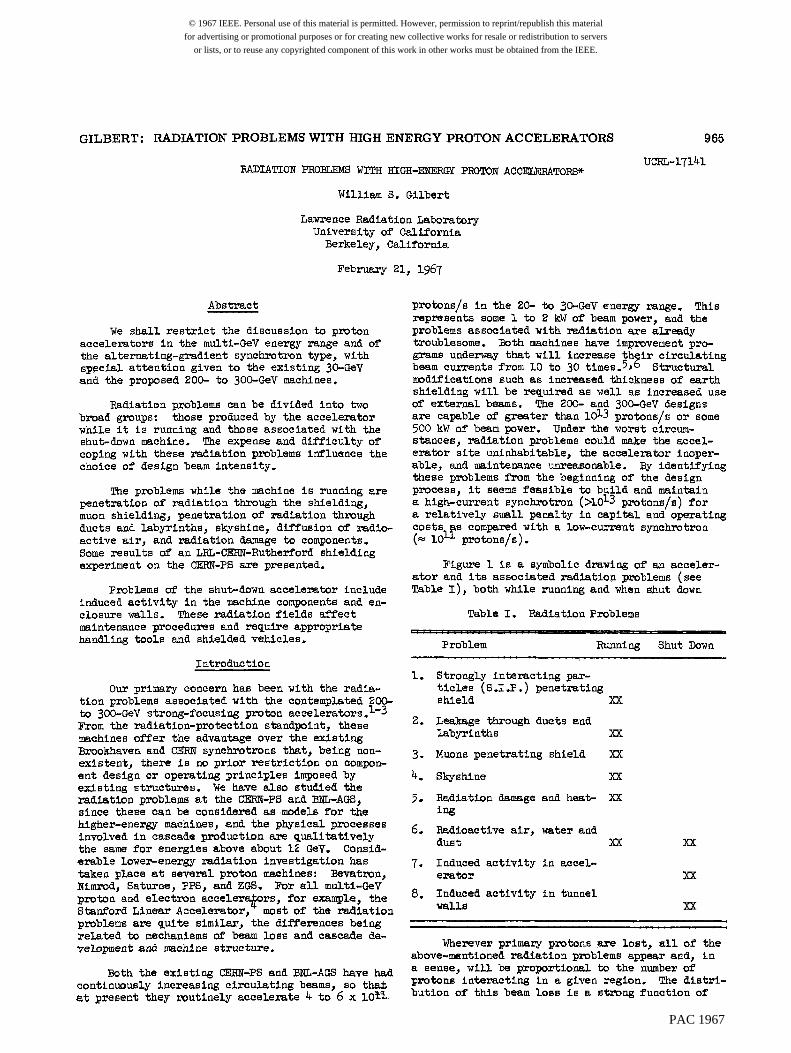
Figure 5 is a plan view of the CERN-PS ehowing the 6-in. d r i l l e d holes f o r o w detectors above the beam o r b i t and to the outside of the ring. Figure 6 is a cross-section view of the accelerator tunnel and shows a line of these holes. Detectors t o be placed above the beam o r b i t were placed i n a 10-ft-long sample holder, and cans of d i r t were placed between samples t o reduce par- t i c l e streaming up these holes. These sample holders were raised and lowered by the use of rope and pulley attached t o the tr ipod shown. samples i n the r a d i a l holes were placed a t beam height and were raised by ropes. l ined with p l a s t i c tubes. the region above the target . One can see the capped tubes and general features. We were par- t i cu la r ly for tunate i n t h a t the ea r th cover here is flat and does*t f a l l to a lower grade as one
The
These holes were Figure 7 is a photo of
PAC 1967
GILBERT: RADIATION PROBLEMS WITH HIGH ENERGY PROTON ACCELERATORS 969
goes outward, as it does over most of the ring. The r a d i a l holes were for the purpose of neasuring attenuation a t g rea t shielding depth, which would not have h e n a8 convenient if the surface were not marconably flat.
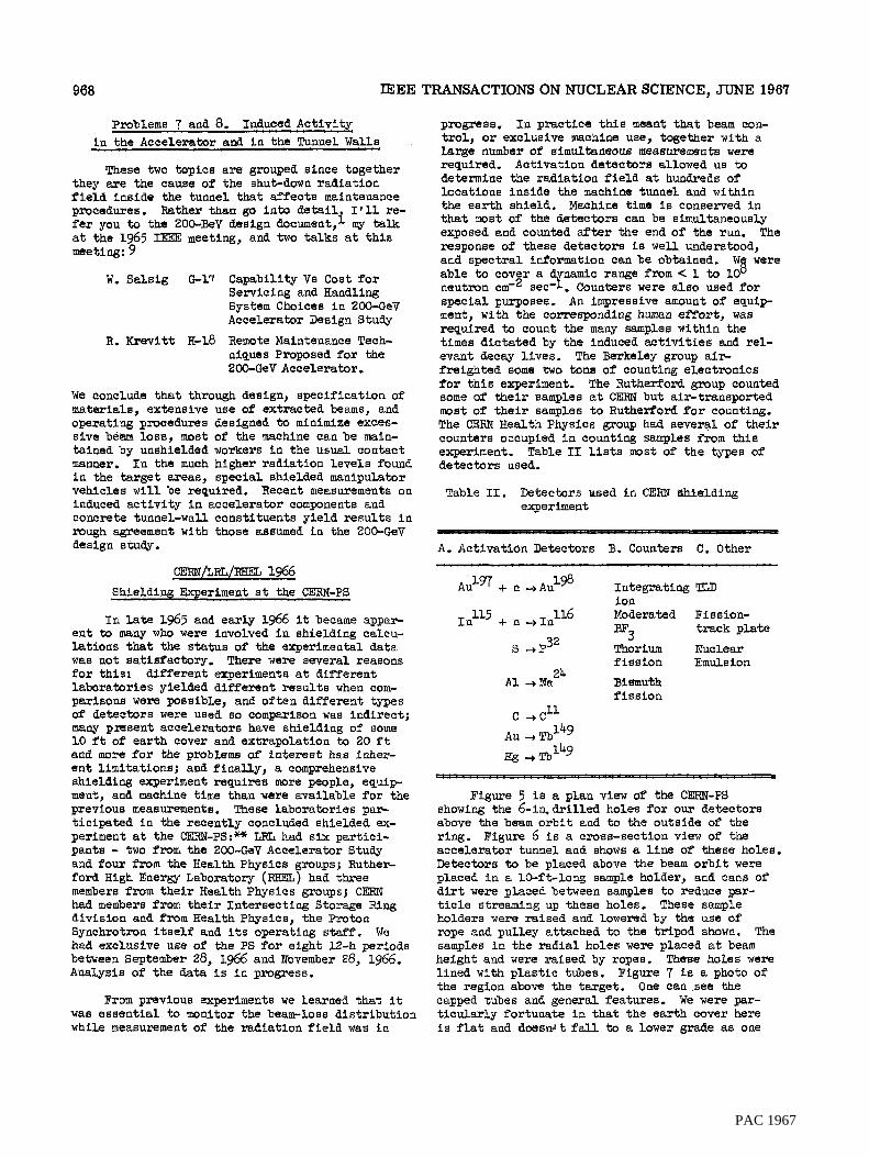
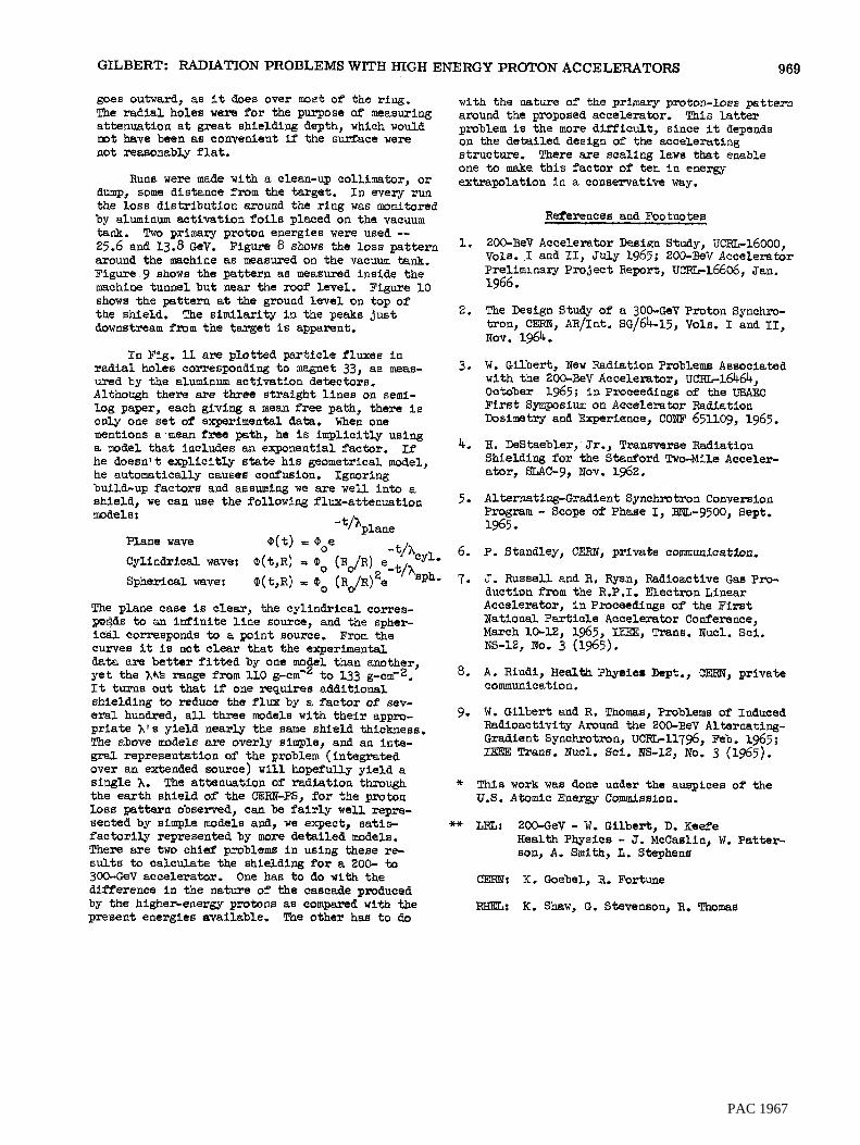
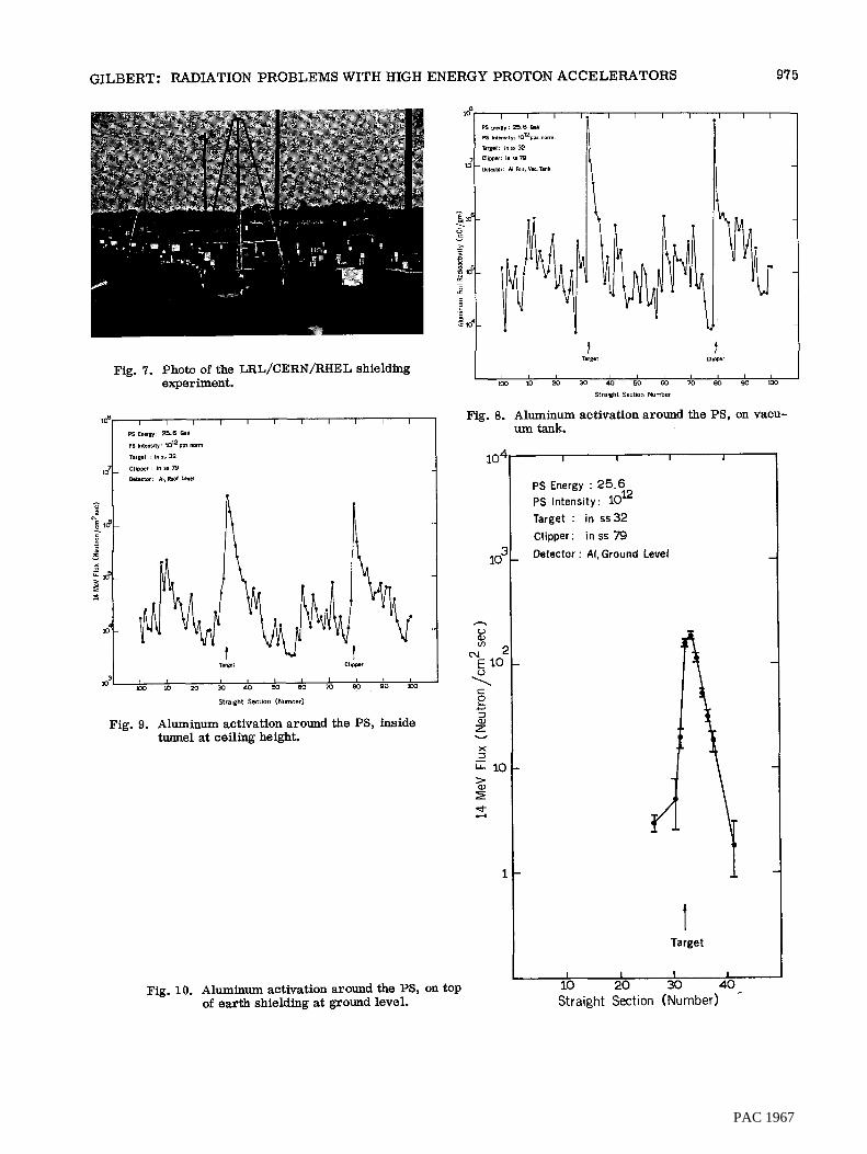
Rum w e r e made with a clean-up c o l l i m t o r , o r dump, some distance f r o m the target. I n every run the loss d i s t r ibu t ion around the r ing wafi monitored by aluminum act ivat ion foi ls placed on the vacuum tank. 25.6 and 13.8 Gcv. Figure 8 shows the loss p a t t e r n around the machine as measurea on the vacuum tank. Figure 9 shows the pat tern as meaaured inside the machine tunnel bGt near the roof level. Figure 10 shows the pat tern a t the ground leve l on top of the shleld. downstream f r o m the target is apparent.
’pwo primary proton energies were used --
The s imi la r i ty i n the peaks j u s t
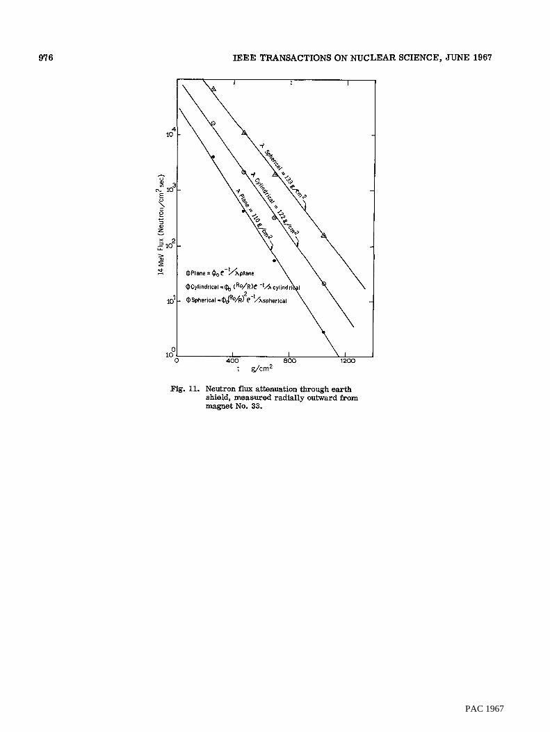
I n Fig. 11 are plot ted par t ic le fluxes i n r a d i a l holes corresponding t o magnet 33, a s meas- ured by the aluminum act ivat ion detectors. Although there axe three s t ra ight l i n e s on seml- log paper, each giving a mean free path, there is only one set of experimental data. When one mentions a mean free path, he is implici t ly using a model t h a t includes an exponential fac*r. he doesn’t e x p l i c i t l y state h i s geometrical model, he automatically causes co&wlon. Ignoring build-up factora and assuming we are w e l l in to e shield, we can me the following flux-attenuation
If
mdelsr - t/’plane Plana wave Q ( t ) E Ooe
Spherical wave; Q ( t , R ) = (Po (RdR) e sph.
Cylindrical wave: Q(t,R) = Oo (R$l)2e-t,A ‘t&yl,
The plane case is clear, the cy l ind r i ca l correa- wpF3ds to an i n f i n i t e l i n e source, and the spher- ical COrreSpOndE to a point source. curves it is not c lear that the experimental data are b e t t e r f i t t e d by one mo y e t the ?,4k range from 110 g-cm-’to 133 g-cm-2, It turns out that if one requires addi t ional shielding to reduce the flux by a factor of sev- eral hundred, a l l three models with t h e i r appro- p r i a t e 1’s yield nearly the same shleld thickness. The above models are overly simple, and an i n t e - gral representation of the problem ( integrated over an extended source) w i l l hopefully yield a single ?,. The attenuation of r ad ia t ion through the ea r th shield of the CERm-PS, for the proton loss pat tern observed, can be f a i r l y w e l l repre- sented by simple models and, w e expect, satis- f a c t o r i l y represented by more & t a i l e d models. There a r e two chief problems i n using these re- s u l t s to calculate the shielaing f o r a 200- to 30Q-GeV accelerator. One has t o do with the difference i n the nature of the cascde produced by the higher-energy protons as compared with the present energies available. The other haa t o Bo
From the
1 than another,
with the n a t u r e of the primary proton-loss pat tern around the proposed accelerator. This latter problem i s the more d i f f i c u l t , since it depends on the detai led design of the accelerating structure. one t o make t h i s f a c t o r of ten i n energy extrapolation I n a conservative way.
Thnre are scaling l a w s t h a t enab le
References and Footnotes
1.
2.
3.
4.
5.
6.
7.
8.
9-
200-EeV Accelerator Deaiqn Study, UCRL-16000, Vole. .I and 11, July 1965; 200-BeV Accelerator Preliminary P ro jec t Report, um16606, Jan.
The Design Study of a 300-GeV Proton Synchro- tron, CERN, AR/Int. SG/64-15, Vols, I and 11,
1966.
Nov. 1964.
W. Gilbert, New Radiation Problems Associated with the 200-3eV Accelerator, ucRG16464, October 1965; i n Proceedings of the USAEC F i r s t Symposium on Accelerator h d i a t i o a Dosimetry and Experience, COKF 651109, 1965.
B. DaStaebler,‘ Jr., Transverse Radiation Shielding f o r the Stauford Two-Mile Acceler- a tor , mC-9, Nov. 1962.
Alternating-Gradient Synchrotron Conversion Program - Scope of Phaee I, BNL-9500, Sept.
P. Standley, CERN, private comunication,
J. Russell and R. Ryan, Radioactive Gas Pro- duction from the R.P.I. Electron Linear Accelerator, i n Proceedings of the F i r s t National P a r t i c l e Accelerator Conference, March 10-12, 1965, IEEE, Trans. Nucl. Sci.
A. Rindi, Health physic^ Bspf., CERN, private communication.
1965.
NS-12, No. 3 (1965).
W. Gi lber t and R. Thomaa, Problem0 of Induced Radioactivity Around the 200-BeV Alternating- Gradient Synchrotron, UcRE11796, Feb. 1965 ; IFEE Trans, Nucl. Sci. NS-12, No. 3 (1965).
* This work was done under the ausplcee of the U.S. Atomic Energy Commission.
2oO-GeV - W. Gilbert, D. K e e f e Health Physics - J. Mccaslin, W. Patter- son, A. Smith, L. Stephens
K, Goebel, R. Fortune
K. Shaw, G. Stevenson, R, Thomas
PAC 1967

970 IEEE TRANSACTIONS ON NUCLEAR SCIENCE, JUNE 1967
Fig. 1. Schematic representation of radiation problems.
Shielding Over Non rget Areas Only
---I---------- I -20' After Improvement
! Program 40' Target Area
I
. . .. -,i.. .& , .
200 BeV BNL- AGS Cern - PS SLAC
Fig. 2. Comparison cross sections of AGS, PS, SLAC, and 200-GeV accelerators.
PAC 1967

GILBERT: RADIATION PROBLEMS WITH HIGH ENERGY PROTON ACCELERATORS
I I I I I
40m Concrete - 10m Iron *
I 2000
Forward (shielding for S.1.R
4000 6000 8000 lop00 1 y(gm cm-2)
300
97 1
Fig. 3. Transmission vs shielding for strongly inter- acting particles (S.I.P.) and muons for inci- dent 200-GeV protons.
PAC 1967

97 2 IEEE TRANSACTIONS ON NUCLEAR SCIENCE, JUNE 1967
Stallon J-EL
Bending Magnet C-Type
acuum Chamber
.. .,*-
E P B Target Stat' ion J-BR and J-BL
Fig. 4. EPB target stations for the 200-GeV proton accelerator.
PAC 1967

GILBERT: RADIATION PROBLEMS WITH HIGH ENERGY PROTON ACCELERATORS 973
Fig. 5. Plan view of the LRL/CERN/RHEL shielding experiment.
PAC 1967

974
I
I
PAC 1967
GILBERT: RADIATION PROBLEMS WITH HIGH ENERGY PROTON ACCELERATORS 97 5
Tarel Clipper
Fig. 7. Photo of the LRL/CERN/RHEL shielding experiment .
I I I I I I I
t T.,@
4 CIIPP'
I I I I I I I I I I I tca io 20 30 40 50 ea 70 eo 90 1w
Straight Section Number
Fig. 8. Aluminum activation around the PS, on vacu-
Fig. 10. Aluminum activation around the PS, on top of earth shielding at ground level.
um tank.
I I I I
PS Energy : 25.6 PS Intensity: 10 Target : in ss32 Clipper: in ss 79 Oetector : Al, Ground Level
12
Target
I I I I
10 20 30 40 Straight Section (Number) -
PAC 1967
97 6 IEEE TRANSACTIONS ON NUCLEAR SCIENCE, JUNE 1967
\ I I \ I
400 800 1200 t g/cm2
Fig. 11. Neutron flux attenuation through earth shield, measured radially outward from magnet No. 33.
PAC 1967